EP3515610B1 - Werkzeug, vorzugsweise zur entgratung und/oder reinigung von kunststoffbauteilen - Google Patents
Werkzeug, vorzugsweise zur entgratung und/oder reinigung von kunststoffbauteilen Download PDFInfo
- Publication number
- EP3515610B1 EP3515610B1 EP17768418.0A EP17768418A EP3515610B1 EP 3515610 B1 EP3515610 B1 EP 3515610B1 EP 17768418 A EP17768418 A EP 17768418A EP 3515610 B1 EP3515610 B1 EP 3515610B1
- Authority
- EP
- European Patent Office
- Prior art keywords
- shaft
- tool
- processing element
- strand
- receiving
- Prior art date
- Legal status (The legal status is an assumption and is not a legal conclusion. Google has not performed a legal analysis and makes no representation as to the accuracy of the status listed.)
- Active
Links
Images
Classifications
-
- B—PERFORMING OPERATIONS; TRANSPORTING
- B08—CLEANING
- B08B—CLEANING IN GENERAL; PREVENTION OF FOULING IN GENERAL
- B08B7/00—Cleaning by methods not provided for in a single other subclass or a single group in this subclass
- B08B7/02—Cleaning by methods not provided for in a single other subclass or a single group in this subclass by distortion, beating, or vibration of the surface to be cleaned
-
- B—PERFORMING OPERATIONS; TRANSPORTING
- B08—CLEANING
- B08B—CLEANING IN GENERAL; PREVENTION OF FOULING IN GENERAL
- B08B1/00—Cleaning by methods involving the use of tools
- B08B1/30—Cleaning by methods involving the use of tools by movement of cleaning members over a surface
- B08B1/32—Cleaning by methods involving the use of tools by movement of cleaning members over a surface using rotary cleaning members
- B08B1/34—Cleaning by methods involving the use of tools by movement of cleaning members over a surface using rotary cleaning members rotating about an axis parallel to the surface
-
- B—PERFORMING OPERATIONS; TRANSPORTING
- B08—CLEANING
- B08B—CLEANING IN GENERAL; PREVENTION OF FOULING IN GENERAL
- B08B7/00—Cleaning by methods not provided for in a single other subclass or a single group in this subclass
- B08B7/02—Cleaning by methods not provided for in a single other subclass or a single group in this subclass by distortion, beating, or vibration of the surface to be cleaned
- B08B7/024—Rotary scalers
-
- B—PERFORMING OPERATIONS; TRANSPORTING
- B23—MACHINE TOOLS; METAL-WORKING NOT OTHERWISE PROVIDED FOR
- B23B—TURNING; BORING
- B23B51/00—Tools for drilling machines
- B23B51/10—Bits for countersinking
- B23B51/101—Deburring tools
-
- B—PERFORMING OPERATIONS; TRANSPORTING
- B24—GRINDING; POLISHING
- B24B—MACHINES, DEVICES, OR PROCESSES FOR GRINDING OR POLISHING; DRESSING OR CONDITIONING OF ABRADING SURFACES; FEEDING OF GRINDING, POLISHING, OR LAPPING AGENTS
- B24B27/00—Other grinding machines or devices
- B24B27/033—Other grinding machines or devices for grinding a surface for cleaning purposes, e.g. for descaling or for grinding off flaws in the surface
- B24B27/04—Grinding machines or devices in which the grinding tool is supported on a swinging arm
-
- B—PERFORMING OPERATIONS; TRANSPORTING
- B24—GRINDING; POLISHING
- B24D—TOOLS FOR GRINDING, BUFFING OR SHARPENING
- B24D13/00—Wheels having flexibly-acting working parts, e.g. buffing wheels; Mountings therefor
- B24D13/02—Wheels having flexibly-acting working parts, e.g. buffing wheels; Mountings therefor acting by their periphery
- B24D13/04—Wheels having flexibly-acting working parts, e.g. buffing wheels; Mountings therefor acting by their periphery comprising a plurality of flaps or strips arranged around the axis
- B24D13/045—Wheels having flexibly-acting working parts, e.g. buffing wheels; Mountings therefor acting by their periphery comprising a plurality of flaps or strips arranged around the axis comprising flaps not covering the entire periphery of the wheel
-
- B—PERFORMING OPERATIONS; TRANSPORTING
- B24—GRINDING; POLISHING
- B24D—TOOLS FOR GRINDING, BUFFING OR SHARPENING
- B24D13/00—Wheels having flexibly-acting working parts, e.g. buffing wheels; Mountings therefor
- B24D13/02—Wheels having flexibly-acting working parts, e.g. buffing wheels; Mountings therefor acting by their periphery
- B24D13/06—Wheels having flexibly-acting working parts, e.g. buffing wheels; Mountings therefor acting by their periphery the flaps or strips being individually attached
-
- B—PERFORMING OPERATIONS; TRANSPORTING
- B26—HAND CUTTING TOOLS; CUTTING; SEVERING
- B26D—CUTTING; DETAILS COMMON TO MACHINES FOR PERFORATING, PUNCHING, CUTTING-OUT, STAMPING-OUT OR SEVERING
- B26D1/00—Cutting through work characterised by the nature or movement of the cutting member or particular materials not otherwise provided for; Apparatus or machines therefor; Cutting members therefor
- B26D1/01—Cutting through work characterised by the nature or movement of the cutting member or particular materials not otherwise provided for; Apparatus or machines therefor; Cutting members therefor involving a cutting member which does not travel with the work
- B26D1/12—Cutting through work characterised by the nature or movement of the cutting member or particular materials not otherwise provided for; Apparatus or machines therefor; Cutting members therefor involving a cutting member which does not travel with the work having a cutting member moving about an axis
-
- B—PERFORMING OPERATIONS; TRANSPORTING
- B26—HAND CUTTING TOOLS; CUTTING; SEVERING
- B26D—CUTTING; DETAILS COMMON TO MACHINES FOR PERFORATING, PUNCHING, CUTTING-OUT, STAMPING-OUT OR SEVERING
- B26D1/00—Cutting through work characterised by the nature or movement of the cutting member or particular materials not otherwise provided for; Apparatus or machines therefor; Cutting members therefor
- B26D1/01—Cutting through work characterised by the nature or movement of the cutting member or particular materials not otherwise provided for; Apparatus or machines therefor; Cutting members therefor involving a cutting member which does not travel with the work
- B26D1/12—Cutting through work characterised by the nature or movement of the cutting member or particular materials not otherwise provided for; Apparatus or machines therefor; Cutting members therefor involving a cutting member which does not travel with the work having a cutting member moving about an axis
- B26D1/25—Cutting through work characterised by the nature or movement of the cutting member or particular materials not otherwise provided for; Apparatus or machines therefor; Cutting members therefor involving a cutting member which does not travel with the work having a cutting member moving about an axis with a non-circular cutting member
- B26D1/34—Cutting through work characterised by the nature or movement of the cutting member or particular materials not otherwise provided for; Apparatus or machines therefor; Cutting members therefor involving a cutting member which does not travel with the work having a cutting member moving about an axis with a non-circular cutting member moving about an axis parallel to the line of cut
- B26D1/36—Cutting through work characterised by the nature or movement of the cutting member or particular materials not otherwise provided for; Apparatus or machines therefor; Cutting members therefor involving a cutting member which does not travel with the work having a cutting member moving about an axis with a non-circular cutting member moving about an axis parallel to the line of cut and rotating continuously in one direction during cutting, e.g. mounted on a rotary cylinder
-
- B—PERFORMING OPERATIONS; TRANSPORTING
- B26—HAND CUTTING TOOLS; CUTTING; SEVERING
- B26D—CUTTING; DETAILS COMMON TO MACHINES FOR PERFORATING, PUNCHING, CUTTING-OUT, STAMPING-OUT OR SEVERING
- B26D1/00—Cutting through work characterised by the nature or movement of the cutting member or particular materials not otherwise provided for; Apparatus or machines therefor; Cutting members therefor
- B26D1/01—Cutting through work characterised by the nature or movement of the cutting member or particular materials not otherwise provided for; Apparatus or machines therefor; Cutting members therefor involving a cutting member which does not travel with the work
- B26D1/547—Cutting through work characterised by the nature or movement of the cutting member or particular materials not otherwise provided for; Apparatus or machines therefor; Cutting members therefor involving a cutting member which does not travel with the work having a wire-like cutting member
-
- B—PERFORMING OPERATIONS; TRANSPORTING
- B26—HAND CUTTING TOOLS; CUTTING; SEVERING
- B26D—CUTTING; DETAILS COMMON TO MACHINES FOR PERFORATING, PUNCHING, CUTTING-OUT, STAMPING-OUT OR SEVERING
- B26D1/00—Cutting through work characterised by the nature or movement of the cutting member or particular materials not otherwise provided for; Apparatus or machines therefor; Cutting members therefor
- B26D1/01—Cutting through work characterised by the nature or movement of the cutting member or particular materials not otherwise provided for; Apparatus or machines therefor; Cutting members therefor involving a cutting member which does not travel with the work
- B26D1/547—Cutting through work characterised by the nature or movement of the cutting member or particular materials not otherwise provided for; Apparatus or machines therefor; Cutting members therefor involving a cutting member which does not travel with the work having a wire-like cutting member
- B26D1/553—Cutting through work characterised by the nature or movement of the cutting member or particular materials not otherwise provided for; Apparatus or machines therefor; Cutting members therefor involving a cutting member which does not travel with the work having a wire-like cutting member with a plurality of wire-like cutting members
-
- B—PERFORMING OPERATIONS; TRANSPORTING
- B23—MACHINE TOOLS; METAL-WORKING NOT OTHERWISE PROVIDED FOR
- B23B—TURNING; BORING
- B23B2260/00—Details of constructional elements
- B23B2260/036—Cables
-
- B—PERFORMING OPERATIONS; TRANSPORTING
- B26—HAND CUTTING TOOLS; CUTTING; SEVERING
- B26D—CUTTING; DETAILS COMMON TO MACHINES FOR PERFORATING, PUNCHING, CUTTING-OUT, STAMPING-OUT OR SEVERING
- B26D1/00—Cutting through work characterised by the nature or movement of the cutting member or particular materials not otherwise provided for; Apparatus or machines therefor; Cutting members therefor
- B26D1/0006—Cutting members therefor
- B26D2001/006—Cutting members therefor the cutting blade having a special shape, e.g. a special outline, serrations
-
- B—PERFORMING OPERATIONS; TRANSPORTING
- B26—HAND CUTTING TOOLS; CUTTING; SEVERING
- B26D—CUTTING; DETAILS COMMON TO MACHINES FOR PERFORATING, PUNCHING, CUTTING-OUT, STAMPING-OUT OR SEVERING
- B26D1/00—Cutting through work characterised by the nature or movement of the cutting member or particular materials not otherwise provided for; Apparatus or machines therefor; Cutting members therefor
- B26D1/0006—Cutting members therefor
- B26D2001/008—Cutting members therefor in the form of wires
Definitions
- the invention relates to a tool for deburring and/or cleaning a component, i.e. a deburring and/or cleaning tool/device for deburring and/or cleaning components, preferably plastic components, but alternatively also metallic components, wood, ceramic or concrete components, with a shaft and a processing element attached to the shaft in a removable manner.
- the tool can thus be used for deburring components and/or for cleaning materials adhering to component edges and surfaces.
- Various deburring methods are already known in principle from the prior art. In this context, for example, the DE 10 2007 054 523 A1 a deburring tool with a driver designed as a shaft. Manual deburring of components with grinding wheels or blades or similar processing elements is also known in principle.
- the DE 203 20 821 U1 discloses a device for machining workpieces to remove oxide layers, wherein at least one brush is provided which is arranged on a rotating conveyor device.
- the tool has several chains, each of which is attached to a shaft at its front end sections and rear end sections.
- the generic JP S61 283329 A shows a device with a shaft and chains arranged on it at two receiving positions, wherein the receiving positions are designed to be movable relative to each other.
- the DE 34 10 634 A1 describes a descaling head device which has holding elements which are attached via connecting elements which are designed to be articulated or flexible in the form of chain sections or wires.
- a cleaning device for removing metallic deposits from the mold surfaces of metal molds is known, wherein a rotating brush is provided for removing deposits.
- a tool for machining bores is known, wherein a shaft is provided which has two receiving positions for receiving several spring wires.
- the DE 43 10 831 A1 discloses a tool for deburring, in particular undercuts and bore joints. Several wires are twisted together on a shaft and attached to a sleeve at the opposite end, with the shaft and sleeve being movable relative to one another.
- a deburring tool which consists of a wire and a shaft, with the ends of the wire being fixed at one point on the shaft.
- the processing element is designed as a strand/beating strand that is set particularly precisely to remove weak spots such as burrs or material adhesion at the connection point to the component base body using various process control parameters.
- the flexibility of this strand ensures that the tolerances of the tool drive, e.g. by means of a motion machine, and the tolerances of the components are compensated for.
- the tool can be used and operated precisely both stationary and on the motion machine. This means that automated use with a motion machine is particularly effective.
- the deburring/cleaning tool according to the invention is preferably used for deburring and/or cleaning plastic components in all known forms (e.g. as foam, injection molded, cast, extruded components, etc.).
- a spindle drive for example, the deburring/cleaning tool is set in rotation during operation and the burr/flint or the adhesion of material is removed with a geometrically undefined or defined cutting/impact body in the form of the strand.
- the burr is separated at its shear plane to the main body by a repeated impact pulse (depending on the rotational speed of the tool and variant of the tool as well as depending on the feed speed of the automatic movement along the processing edge or surface).
- the process can be adjusted by the strand in such a way that damage to the main body is avoided.
- Different applications require different impact energies, which can easily be achieved by modifying the strand in terms of mass, material, inherent stiffness and geometric shape and/or by modifying the rotational speed, peripheral speed and/or by modifying the prestress of the strand and the contact pressure on the component base body.
- the tool can be cleverly designed for different component dimensions depending on the length of the machining element.
- a receiving notch is provided at a first receiving position of the shaft, into which the strand/processing element protrudes and/or is guided so as to be displaceable, the processing element can be attached to the shaft particularly easily.
- the receiving notch is provided on one end of the shaft, preferably at an upper end of the shaft, so that the strand is also exposed towards one end of the shaft.
- the geometric properties of the strand then enable the formation of a cutting body in the form of the processing element with the help of rotation. If the processing element/strand protrudes from the receiving notch by a certain amount, the strand is designed to be particularly effective as a cutting body.
- the first receiving position is a through hole, preferably a through bore, which runs transversely, more preferably perpendicularly, to a rotation axis of the shaft, with the machining element then protruding into this through hole and/or being guided in a displaceable manner in it.
- This also allows the tool to be designed to be particularly robust.
- the processing element is fastened to the shaft in a second receiving position arranged at a distance from the first receiving position, the processing element is particularly cleverly fixed in its position relative to the shaft. The operational reliability and process reliability are thereby further improved.
- the second receiving position is also designed as a through hole, preferably a through bore, which runs transversely, more preferably perpendicularly, to the axis of rotation of the shaft.
- the structure of the tool is further simplified.
- the processing element is attached to the shaft in a loop-like manner.
- the shape of the loop is also crucial for accessibility to the component.
- the shape of the tool can be adjusted even more flexibly.
- the processing element can be connected or fixed at at least one end to a support arm extending transversely to the axis of rotation of the shaft. This also allows burrs or buildup with a relatively large diameter to be removed.
- each processing element when using two processing elements, one end of each processing element can be clamped to a support arm. This makes the tool particularly suitable for deburring and/or cleaning large diameters.
- the spring pre-tension allows the course/arrangement of the machining element to be cleverly adjusted depending on the speed.
- a piercing body such as a spike
- a piercing body is attached to the shaft, preferably to a front end / front side of the shaft. This facilitates the removal of the waste products that form and enables the tool to enter a closed flint skin.
- a removal element such as a deburring brush, a grinding body, a polishing body, a milling body or a drilling body
- the tool can be used in even more versatile ways.
- the removal element it is also possible to provide another cleaning element on the front end/front side of the shaft, with the cleaning element preferably being designed as a cleaning brush.
- the invention relates to a processing system with a tool according to at least one of the previously described embodiments and a processing machine that receives the tool, such as a motion machine, a robot (e.g. an articulated arm robot) or a CNC machine.
- a processing machine that receives the tool, such as a motion machine, a robot (e.g. an articulated arm robot) or a CNC machine.
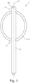
- a tool 1 according to the invention for deburring and cleaning components is shown according to a preferred first embodiment.
- the tool 1 is therefore also referred to or used as a deburring/cleaning tool or deburring and/or cleaning tool.
- the tool 1 has an elongated shaft 2.
- a longitudinal axis of the shaft 2 simultaneously forms an axis of rotation 5 about which the shaft 2 rotates in an operating state of the tool 1.
- the tool 1 has a processing element 3 designed for deburring and/or cleaning.
- the processing element 3 is received/attached to the shaft 2 in a rotationally fixed manner.
- the processing element 3 consists of a flexible/compliant material and is shaped as a strand 4.
- the processing element 3 is therefore formed directly by the flexible strand.
- the strand 4 is so flexible that it deforms/bends/bulges (elastically) depending on the speed of the shaft 2 in the operating state.
- the strand 4 is attached to the shaft 2 in a loop-like manner/as a loop.
- the strand 4 is coupled to the shaft 2 in a rotationally fixed manner/held to the shaft 2 in a rotationally fixed manner/received at two receiving positions 6 and 7 arranged at a distance from one another along the axis of rotation 5.
- the strand 4 is guided through a precisely fitting through hole (preferably a clearance fit) and is thus connected to the shaft 2 in a rotationally fixed manner.
- the strand 4 is preferably guided so as to be displaceable.
- a (precisely fitting (preferably with a clearance fit)) through hole is also provided, into which the strand 4 in turn projects and is rotationally fixedly received in the shaft 2.
- the processing element 3 forms two partially/semicircular (ie partially/semi-elliptical) loops, which extend freely between the receiving positions 6 and 7, i.e. at a distance from the shaft 2.
- the two loops are arranged/formed opposite one another in a plane relative to the shaft 2.
- the strand 4 is used during operation for deburring and/or cleaning, ie the strand 4 removes the burr or adhesion on the component to be deburred or cleaned using its outer side. In doing so, the strand 4 strikes the burr or adhesion to be removed depending on the speed of rotation, so that it is removed.
- the strand 4 bulges outwards from the shaft 2 in the operating state of the tool 1 in the radial direction and thus takes on a stable shape during operation, which depends on the rotation speed and thus the centrifugal force.
- the strand 2 therefore serves as an impact strand in the operating state.
- the strand 4 is received at the receiving positions 6, 7 in such a way that it can be removed again from the shaft 2. This makes it particularly easy to replace the processing element 3 after it has worn out.
- the machining element 3/strand 4 is also set in rotation by turning the shaft 2.
- the rotation and the associated centrifugal force push the strand 4 outwards from the shaft 2.
- This outward-pushed curvature of the strand 4 rolls/slides with its outer shape/outside on the respective component base body.
- the feed movement is preferably generated when the tool 1 is used in a machining system by an automatic motion device in which the tool 1 is then received and guided, e.g. along an edge/surface to be deburred/cleaned.
- the strand 4 has a defined flexibility and deformability, component tolerances and movement tolerances of the automatic motion device are compensated - the strand 4 hugs the component.
- the component can be guided around the tool 1, e.g. by means of an automatic motion device.
- the rotating tool 1 can therefore be fixed (i.e. stationary) in order to only carry out the rotational movement.
- the tool 1 can therefore be operated in a stationary manner.
- the strand 4 itself can be made of a metal material, natural fibers, a plastic, or a ceramic material or combinations of these materials / materials. These materials / strand 4 can also, in principle, be provided with or equipped with more or less abrasive surfaces or additives, depending on the application.
- a second embodiment of the tool 1 is shown, which is, however, basically constructed according to the tool 1 of the first embodiment, which is why only the differences are described below for the sake of brevity.
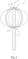
- Fig. 2 the processing element 3 / the strand 4 is shown in two further alternative extensions by two elliptical, dashed lines.
- the length of the strand 4 can be individually selected, depending on the use of the tool 1 and the component to be deburred.
- the dashed lines show alternative extensions of the processing element 3, whereby these are always loop-like.
- the first receiving position 6 is designed somewhat differently than in the first embodiment.
- a receiving notch 8 is used, which is introduced into a front side 18 / a front end of the shaft 2.
- the processing element 3 / the strand 4 extends through the receiving notch 8 and is guided so as to be displaceable in this receiving notch 8.
- the dimensions of the receiving notch 8 are matched to the processing element 3 in such a way that the processing element 3 is attached (precisely fitting (preferably via a clearance fit)) in a rotationally fixed manner in the first receiving position 6.
- the depth of the receiving notch 8 is also matched to the processing element 3 in such a way that the processing element 3 protrudes from the front side 18 of the shaft 2 by a certain amount, e.g. by half or a third of the diameter of the processing element 3.
- This area of the processing element 3 can therefore also be used for processing.
- the strand 4 is thus exposed at the first receiving position 6, so that the geometric properties of the strand 4, with the help of the rotation, represent a cutting body.
- the processing element 3 can be fixed to the shaft 2, for example by means of a screw or the like.
- the tool 1 of the first embodiment can be easily adapted in four further embodiments.
- various elements are attached to the front side 18 / on the shaft 2.
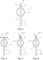
- a mandrel tip 14 is attached to the front side 18.
- the mandrel tip 14 forms a piercing body.
- the mandrel tip 14 is shaped and attached to the shaft 2 in such a way that its tip is aligned along the axis of rotation 5 and is directed away from the shaft 2. This provides a piercing body in the form of the mandrel tip 14, which enables burr material to be pierced during operation.
- removal elements 19 according to the embodiments of the Figs. 4 to 6 on the tool 1 of the first embodiment.
- a deburring brush 15 which is alternatively also designed as a cleaning brush, is attached to the end face 18 / on the shaft 2, wherein the deburring brush 15 has brushes on its radial outer side in relation to the axis of rotation 5.
- a deburring / cleaning brush could alternatively also be used in the axial direction (depending on the machining case), ie the individual brushes would then be aligned in the axial direction.
- a grinding body 16 or alternatively a polishing body, to the front side 18 of the shaft 2 instead of or in addition to the deburring brush 15/cleaning brush.
- This grinding/polishing body 16 has an active surface facing away from the shaft 2, which is radial and/or axial or acts in other angular arrangements.
- a milling tool / a milling body 17 or drill / drill body it is also possible alternatively or additionally to attach a milling tool / a milling body 17 or drill / drill body to the front side 18 / on the shaft 2.
- the remaining structure and the remaining function of the tools 1 of the third to sixth embodiments essentially correspond to the structure and the function of the tool 1 of the first embodiment.
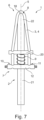
- a seventh embodiment of the tool 1 is shown, not according to the invention.
- This deburring and/or cleaning tool 1 like the tool 1 of the first embodiment, also has a shaft 2, on which the processing element 3 in the form of the strand 4 is received.
- the reception of the processing element 3 is chosen somewhat differently than in the first embodiment.
- the processing element 3 is again attached to the shaft 2.
- the processing element 3 With a first end 10 and a second end 11, the processing element 3 is now attached to a support arm 12, not according to the invention, which extends transversely to the shaft 2 (at the same axial height as the shaft 2).
- the support arm 12 is a rotationally fixed component of the shaft 2/rotationally connected to the shaft 2.
- the support arm 12 extends transversely, namely essentially perpendicularly, to the shaft 2 / to the axis of rotation 5. Each end 10 and 11 of the processing element 3 is clamped into the support arm 12 on a different side of the shaft 2.
- the second receiving position 7 is thus formed here by the support arm 12. From the respective end 10, 11, the processing element 3 extends in the longitudinal direction of the shaft 2 to the first receiving position 6, which in turn is formed here on an end face 18 of the shaft 2.
- the processing element 3 is folded over on the end face 18, so that ultimately a U- / V-shaped folding of the strand 4 is achieved. For this purpose, a notch can be provided on the end face 18.
- the shaft 2 is made up of several parts, namely two parts.
- the two shaft parts 21 and 22 are accommodated/guided so that they can be displaced relative to one another.
- a first shaft part 21 is connected to the first support arm 12 in a displaceably fixed manner.
- a second shaft part 22 in turn has the first receiving position 6 and is displaced relative to the first shaft part 21 by means of a spring element. 9, here a helical compression spring.
- the shaft parts 21 and 22 are prestressed relative to one another in the longitudinal direction of the shaft 2.
- This means that the end face 18 formed on the second shaft part 22 is prestressed relative to the first support arm 12 and thus stretches the processing element 3 in the longitudinal direction of the shaft 2 with a certain prestressing force.
- the processing element 3 is pushed outwards / curved outwards by the centrifugal force during operation, with the centrifugal force acting against a spring force / prestressing force of the spring element 9.
- processing element 3 is guided on each side of the shaft 2 by means of a guide arm 20 (not according to the invention) extending essentially parallel to the support arm 12.
- the guide arm 20 is connected in a rotationally fixed manner to the second shaft part 22.
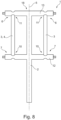
- FIG. 8 A further embodiment of a tool 1 not according to the invention is shown in Fig. 8 shown.
- the tool 1 of this eighth embodiment is again constructed similarly to the tool 1 of the first embodiment.
- this tool 1 has not just a single processing element 3, but two processing elements 3.
- Each processing element 3 is again designed as a flexible strand 4.
- the processing elements 3 are now clamped between two support arms 12 and 13, not according to the invention, which are arranged at a distance from one another in the longitudinal direction of the shaft 2.
- the two support arms 12 and 13 again extend essentially perpendicularly / transversely to the axis of rotation 5.
- the support arms 12, 13 also extend essentially parallel to one another.
- the processing elements 3 are clamped essentially straight between the support arms 12 and 13, seen in the unloaded state / resting state of the tool 1.
- the machining elements 3 extend substantially parallel to the axis of rotation 5.
- each of the two machining elements 3 with its section running freely between the support arms 12 and 13, bulges in the radial direction outwards / away from the shaft 2.
- a basic structure of the tool 1 always consists of a tool shaft 2, on which there is an upper fastening and guide point (first receiving/fastening position 6/upper striking strand fixation) and a lower fastening point (second receiving/fastening position 7/lower striking strand fixation). Between the two fastening points 6, 7, the striking strand 4 is fixed or held in a rotationally fixed manner in a circumferential loop.
- the striking strand 4 is considered a wear component in the tool and can be replaced at any time or modified for other applications.
- the tool 1 can also be designed as a modification with the upper guide point 6 as a notch fixation (receiving notch 8) in order to hold the striking strand 4.
- a mandrel tip or an additional processing tool for alternating processing such as a deburring brush 15, a grinding body/polishing body 16 or a milling tool/drilling tool/drill (milling body 17).
- Another design of the tool 1 contains a pre-tensioning spring element (spring element 9), which gives the impact strand 4 a basic rigidity and a press guide in the upper notch guide point 6.
- the pre-tensioning spring element 9 enables the impact strand 4 to be flexible even when the material is clamped onto the tool 1 without loop formation. In the case of loop formation, the pre-tensioning spring element 9 enables a variable loop geometry depending on the speed and the associated centrifugal force.
- FIG. 8 Another design of the tool 1 not according to the invention in the form of a deburring harp ( Fig. 8 ), which guides the impact strand 4 in a parallel arrangement at a distance from the base body of the component, enables an essentially cylindrical tool geometry in rotation.
- the natural flexibility of the impact strand 4 also enables a conforming behavior (bulging) to the base body of the workpiece / component with this arrangement.
- This variant not according to the invention can also alternatively be designed as a triangle with a central upper impact strand fixation 6 or other geometries as well as with a spring preload element.
- the tool 1 can guide one, two (usually) or more impact strands 4 on itself.
- the tool 1 can be operated stationary or on a motion machine or in another processing machine, such as a CNC milling machine.
- the design according to the invention which is adapted to the conditions such as the drive unit and component geometry and is integrated as far as possible, offers the smallest possible interference contours and thus enables maximum utilization of the degrees of freedom and movement options of the motion machines used, especially for complex three-dimensional contour processing.
- the intended use for plastic processing can also be expanded.
- Metallic materials, wood, ceramics and concrete can also be deburred or cleaned of buildup using this tool arrangement.
- the operating mode of this tool 1 can be both synchronous and counter-rotating.
Landscapes
- Engineering & Computer Science (AREA)
- Mechanical Engineering (AREA)
- Life Sciences & Earth Sciences (AREA)
- Forests & Forestry (AREA)
- Polishing Bodies And Polishing Tools (AREA)
- Cleaning In General (AREA)
- Grinding And Polishing Of Tertiary Curved Surfaces And Surfaces With Complex Shapes (AREA)
- Finish Polishing, Edge Sharpening, And Grinding By Specific Grinding Devices (AREA)
- Auxiliary Devices For Machine Tools (AREA)
Description
- Die Erfindung betrifft ein Werkzeug zum Entgraten und / oder Reinigen eines Bauteils, d.h. ein Entgrat- und / oder Reinigungswerkzeug / eine Vorrichtung zur Entgratung und / oder Reinigung von Bauteilen, vorzugsweise von Kunststoffbauteilen, alternativ jedoch auch von metallischen Bauteilen, Holz-, Keramik- oder Betonbauteilen, mit einem Schaft und einem an dem Schaft wiederabnehmbar angebrachten Bearbeitungselement. Das Werkzeug kann somit zum Entgraten von Bauteilen und/oder zum Abreinigen von an Bauteilkanten und -flächen anhaftenden Materialien genutzt werden. Aus dem Stand der Technik sind bereits prinzipiell verschiedene Entgratungsmethoden bekannt. In diesem Zusammenhang offenbart bspw. die
DE 10 2007 054 523 A1 ein Entgratwerkzeug mit einem als Schaft ausgebildeten Mitnehmer. Auch eine manuelle Entgratung von Bauteilen mit Schleifkörpern oder Klingen oder ähnlichen Bearbeitungselementen ist prinzipiell bekannt. - Die
DE 203 20 821 U1 offenbart eine Vorrichtung zum Bearbeiten von Werkstücken zum Entfernen von Oxidschichten, wobei wenigstens eine Bürste vorgesehen, die an einer umlaufenden Fördereinrichtung angeordnet ist. - Aus der
US 6 231 430 B1 ist ein Werkzeug zur Reinigung von Kohlenstoffelektroden bekannt. Das Werkzeug weist mehrere Ketten auf, die jeweils an ihren vorderen Endabschnitten und hinteren Endaschnitten an einem Schaft befestigt sind. - Die gattungsgemässe
JP S61 283329 A - Die
DE 34 10 634 A1 beschreibt ein Entzunderungs- Kopfgerät, das Halteelemente aufweist, welche über Verbindungselemente, die gelenkig oder biegsam in Form von Kettenabschnitten oder Drähten ausgestaltet sind, angebracht sind. - Aus der
US 2006/021408 A1 ist eine Reinigungsvorrichtung zum Entfernen von metallischen Ablagerungen von den Formoberflächen von Metallformwerkzeugen bekannt, wobei eine drehbare Bürste zum Entfernen von Ablagerungen vorgesehen ist. Aus derDE 40 00 403 A1 ist ein Werkzeug zur Bearbeitung von Bohrungen bekannt, wobei ein Schaft vorgesehen ist, der zwei Aufnahmepositionen zur Aufnahme von mehreren federnden Drähten aufweist. - Die
DE 43 10 831 A1 offenbart ein Werkzeug zum Entgraten, insbesondere von Hinterschneidungen und Bohrungsstoßstellen. Dabei sind mehrere Drähte verdrillt an einem Schaft und am gegenüberliegenden Ende an einer Hülse angebracht, wobei Schaft und Hülse zueinander beweglich sind. - Aus der
US 5 158 405 A ist eine Entgratungswerkzeug bekannt, das aus einem Draht und einem Schaft besteht, wobei die Enden des Drahts an einer Stelle am Schaft fixiert sind. - Die bisherigen Entgratungsmethoden haben den Nachteil, dass häufig keine stabile Prozessführung möglich ist. Zudem kann ein relativ hoher Personaleinsatz notwendig sein, der auch eine lange Taktzeit mit sich bringt. Weiterhin schwankt die Qualität der Entgratung relativ stark, sodass es zu einer hohen Ausschussrate kommen kann. Außerdem kommt es bei den bisher bekannten manuellen sowie maschinellen Entgratungsmethoden häufig zu einer relativ hohen Belastung des Bauteilgrundkörpers und folglich zu einem relativ starken Abtrag von Material am Bauteilgrundkörper (Gutteil).
- Es ist daher die Aufgabe der vorliegenden Erfindung, diese aus dem Stand der Technik bekannten Nachteile zu beheben und insbesondere ein Werkzeug zur Verfügung zu stellen, das eine schonende sowie reproduzierbare Entgratung / Reinigung ermöglichen soll.
- Dies wird erfindungsgemäß mit den Merkmalen des Anspruchs 1 gelöst.
- Dadurch wird das Bearbeitungselement als Strang / Schlagstrang ausgeführt, der auf eine Schwachstellenabtrennung eines Grates oder einer Materialanhaftung an der Anbindestelle zum Bauteilgrundkörper über verschiedene Parameter der Prozessführung besonders präzise eingestellt ist. Ein Ausgleich der Toleranzen des Werkzeugantriebs, bspw. durch einen Bewegungsautomaten, sowie der Toleranzen der Bauteile wird durch die Nachgiebigkeit dieses Stranges gewährleistet. Das Werkzeug kann sowohl stationär als auch am Bewegungsautomaten präzise eingesetzt und betrieben werden. Somit ist auch eine automatisierte Anwendung mit einem Bewegungsautomaten besonders effektiv.
- In anderen Worten ausgedrückt, dient das erfindungsgemäße Entgrat- / Reinigungswerkzeug vorzugsweise zum Entgraten und / oder Reinigen von Kunststoffbauteilen in allen bekannten Ausprägungen (bspw. als Schaum-, Spritzguss-, Guss-, Extrusionsbauteil, usw.). Mit Hilfe bspw. eines Spindelantriebs wird das Entgrat- / Reinigungswerkzeug im Betrieb in Rotation versetzt und der Grat / Flitt / Flint oder die Anhaftung von Material mit geometrisch unbestimmtem oder bestimmten Schneid- / Schlagkörper in Form des Stranges abgetragen. Der Grat wird durch einen wiederholten Schlagimpuls (abhängig von Rotationsdrehzahl des Werkzeuges und Variante des Werkzeuges sowie abhängig von der Vorschubgeschwindigeit des Bewegungsautomaten entlang der Bearbeitungskante oder -fläche) an seiner Scherebene zum Hauptkörper abgetrennt. Da der Schlagenergiebedarf zum Abtrennen des Grates relativ zum Schlagenergiebedarf zum Beschädigen der Oberfläche des Hauptkörpers sehr gering ist, ist der Prozess durch den Strang so einstellbar, dass eine Beschädigung des Hauptkörpers vermieden wird. Unterschiedliche Anwendungsfälle erfordern unterschiedliche Schlagenergien, wobei dies leicht durch Abwandlung des Stranges in Masse, Material, Eigensteifigkeit und geometrischer Ausprägung und/oder durch Abwandlung der Rotationsgeschwindigkeit, Umfangsgeschwindigkeit und/oder durch Abwandlung der Vorspannung des Stranges sowie des Anpressdruckes an den Bauteilgrundkörper erfolgt.
- Weitere vorteilhafte Ausführungsformen sind in den Unteransprüchen beansprucht und nachfolgend näher erläutert.
- Ist das Bearbeitungselement an dem Schaft an zwei entlang einer Drehachse des Schaftes beabstandet angeordneten Aufnahmepositionen drehfest aufgenommen oder fixiert, ist das Werkzeug geschickt in Abhängigkeit der Länge des Bearbeitungselementes für unterschiedliche Bauteilmaße ausführbar.
- Wenn erfindungsgemäß eine Aufnahmekerbe an einer ersten Aufnahmeposition des Schaftes vorgesehen ist, in der der Strang / das Bearbeitungselement hinein ragt und/oder verschiebbar geführt ist, ist das Bearbeitungselement besonders einfach an dem Schaft anbringbar.
- In diesem Zusammenhang ist es auch vorteilhaft, wenn die Aufnahmekerbe an einer Stirnseite des Schaftes, vorzugsweise an einem oberen Ende des Schaftes, vorgesehen ist, sodass auch der Strang zu einer Stirnseite des Schaftes hin offengelegt ist. Dann ermöglichen die geometrischen Eigenschaften des Stranges unter Mitwirkung der Rotation die Ausbildung eines Schneidkörpers in Form des Bearbeitungselementes. Ragt das Bearbeitungselement / der Strang um ein gewisses Maß aus der Aufnahmekerbe heraus, ist der Strang als Schneidkörper besonders effektiv ausgeführt.
- Alternativ erfindungsgemäß hierzu ist es jedoch auch möglich die erste Aufnahmeposition als ein Durchgangsloch, bevorzugt eine Durchgangsbohrung, das quer, weiter bevorzugt senkrecht, zu einer Drehachse des Schaftes verläuft, auszubilden, wobei das Bearbeitungselement dann wiederum in dieses Durchgangsloch hinein ragt und/oder verschiebbar in diesem geführt ist. Auch dadurch lässt sich das Werkzeug besonders robust ausbilden.
- Ist das Bearbeitungselement erfindungsgemäß an einer zu der ersten Aufnahmeposition beabstandet angeordneten zweiten Aufnahmeposition an dem Schaft befestigt, ist das Bearbeitungselement in seiner Lage relativ zum Schaft besonders geschickt festgelegt. Die Betriebssicherheit und die Prozesssicherheit werden dadurch weiter verbessert.
- Die zweite Aufnahmeposition ist erfindungsgemäß ebenfalls als ein Durchgangsloch, bevorzugt eine Durchgangsbohrung, das quer, weiter bevorzugt senkrecht, zu der Drehachse des Schaftes verläuft, ausgeführt.
- Ist das Bearbeitungselement zwischen den Aufnahmepositionen frei verlaufend, d.h. beabstandet zu dem Schaft verlaufend, ist der Aufbau des Werkzeuges weiter vereinfacht.
- In diesem Zusammenhang ist es besonders zweckmäßig, wenn das Bearbeitungselement schlaufenartig an dem Schaft angebracht ist. Dadurch kann über den Führungsverlauf des Stranges die Schlaufenausprägung und die Nachgiebigkeit des Stranges beeinflusst werden. Die Schlaufenform ist weiterhin entscheidend für die Zugänglichkeit am Bauteil.
- Sind mehrere, vorzugsweise zwei, Bearbeitungselemente mit dem Schaft verbunden, ist die Form des Werkzeuges noch flexibler einstellbar.
- Nicht erfindungsgemäß kann das Bearbeitungselement an zumindest einem Ende an einem sich quer zu der Drehachse des Schaftes erstreckenden Tragarm angebunden oder fixiert sein. Dadurch lassen sich auch Grate oder Anhaftungen mit relativ großem Durchmesser abtragen.
- Nicht erfindungsgemäß kann bei Verwendung von zwei Bearbeitungselementen jeweils ein Ende des jeweiligen Bearbeitungselementes an einem Tragarm eingespannt sein. Dadurch wird das Werkzeug besonders geschickt für das Entgraten und / oder Reinigen von großen Durchmessern eingesetzt.
- Wenn das Bearbeitungselement mittels eines Federelementes an dem Schaft vorgespannt gehalten ist, lässt sich durch die Federvorspannung der Verlauf / die Anordnung des Bearbeitungselementes in Abhängigkeit der Drehzahl geschickt einstellen.
- Zudem ist es vorteilhaft, wenn an dem Schaft, vorzugsweise an einem stirnseitigen Ende / einer Stirnseite des Schaftes, ein Durchstoßkörper, wie eine Dornspitze, angebracht ist. Somit wird die Abführung der sich bildenden Abfallprodukte erleichtert und das Eintreten des Werkzeuges in eine geschlossenen Flitt- / Flint- / Grathaut ermöglicht.
- Wenn an dem Schaft, vorzugsweise an einem stirnseitigen Ende / einer Stirnseite des Schaftes, ein Abtragelement, wie eine Entgratbürste, ein Schleifkörper, ein Polierkörper, ein Fräskörper oder ein Bohrkörper angebracht ist, ist das Werkzeug noch vielseitiger einsetzbar. Statt dem Abtragelement ist es auch möglich ein weiteres Reinigungselement an dem stirnseitigen Ende / der Stirnseite des Schaftes vorzusehen, wobei das Reinigungselement vorzugsweise als eine Reinigungsbürste ausgeführt ist.
- Des Weiteren betrifft die Erfindung ein Bearbeitungssystem mit einem Werkzeug nach zumindest einer der zuvor beschriebenen Ausführungen sowie einer das Werkzeug aufnehmenden Bearbeitungsmaschine, wie einem Bewegungsautomaten, einem Roboter (z.B. ein Gelenkarmroboter) oder einer CNC-Maschine. Dadurch ist eine besonders präzise Entgratungs- bzw. Reinigungsmethode umgesetzt.
- Die Erfindung wird nun nachfolgend anhand von Figuren näher erläutert, in welchem Zusammenhang auch verschiedene Ausführungsbeispiele beschrieben sind.
- Es zeigen:
- Fig. 1
- eine Draufsicht auf ein erfindungsgemäßes Werkzeug zum Reinigen und/oder Entgraten nach einem ersten Ausführungsbeispiel, wobei ein als Strang ausgebildetes Bearbeitungselement schlaufenförmig an einem Schaft des Werkzeuges aufgenommen ist,
- Fig. 2
- eine Draufsicht auf ein erfindungsgemäßes Werkzeug nach einem zweiten Ausführungsbeispiel, wobei das Bearbeitungselement an einer stirnseitig angebrachten Aufnahmekerbe des Schaftes entlang seiner Erstreckung quer zum Schaft aufgenommen sowie geführt ist,
- Fig. 3
- eine Draufsicht auf ein erfindungsgemäßes Werkzeug nach einem dritten Ausführungsbeispiel, wobei das Werkzeug ähnlich zu dem Werkzeug der
Fig. 1 aufgebaut ist, nun jedoch mit einer zusätzlichen Dornspitze versehen ist, - Fig. 4
- eine Draufsicht auf ein erfindungsgemäßes Werkzeug nach einem vierten Ausführungsbeispiel, wobei das Werkzeug ähnlich zu dem Werkzeug der
Fig. 1 aufgebaut ist, nun jedoch mit einer zusätzlichen Entgratbürste versehen ist, - Fig. 5
- eine Draufsicht auf ein erfindungsgemäßes Werkzeug nach einem fünften Ausführungsbeispiel, wobei das Werkzeug ähnlich zu dem Werkzeug der
Fig. 1 aufgebaut ist, nun jedoch mit einem zusätzlichen Schleifkörper versehen ist, - Fig. 6
- eine Draufsicht auf ein erfindungsgemäßes Werkzeug nach einem sechsten Ausführungsbeispiel, wobei das Werkzeug ähnlich zu dem Werkzeug der
Fig. 1 aufgebaut ist, nun jedoch mit einem zusätzlichen Fräskörper versehen ist, - Fig. 7
- eine Draufsicht auf ein nicht erfindungsgemäßes Werkzeug nach einem siebten Ausführungsbeispiel, dessen Bearbeitungselement in Form eines Stranges mittels eines Federelementes an dem Schaft vorgespannt angeordnet ist, und
- Fig. 8
- eine Draufsicht auf ein nicht erfindungsgemäßes Werkzeug nach einem achten Ausführungsbeispiel, wobei mit dem Schaft zwei Tragarme ausgebildet sind, zwischen denen jeweils zwei Bearbeitungselemente eingespannt sind.
- Die Figuren sind lediglich schematischer Natur und dienen ausschließlich dem Verständnis der Erfindung. Die gleichen Elemente sind mit denselben Bezugszeichen versehen. Auch können die verschiedenen Ausführungsbeispiele in ihrer Ausprägung frei miteinander kombiniert werden.
- In
Fig. 1 ist ein erfindungsgemäßes Werkzeug 1 zum Entgraten sowie Reinigen von Bauteilen nach einem bevorzugten ersten Ausführungsbeispiel dargestellt. Das Werkzeug 1 ist daher auch als Entgrat- / Reinigungswerkzeug oder Entgrat- und/oder Reinigungswerkzeug bezeichnet bzw. eingesetzt. Das Werkzeug 1 weist einen sich länglich erstreckenden Schaft 2 auf. Eine Längsachse des Schafts 2 bildet gleichzeitig eine Drehachse 5 aus, um die der Schaft 2 in einem Betriebszustand des Werkzeuges 1 rotiert. Zudem weist das Werkzeug 1 ein für die Entgratung und / oder Reinigung ausgebildetes Bearbeitungselement 3 auf. Das Bearbeitungselement 3 ist an dem Schaft 2 drehfest aufgenommen / angebracht. - Das Bearbeitungselement 3 besteht aus einem flexiblen / nachgiebigen Material und ist als Strang 4 ausgeformt. Das Bearbeitungselement 3 ist daher durch den flexiblen Strang unmittelbar ausgebildet. Der Strang 4 ist derart flexibel, dass er sich in Abhängigkeit einer Drehzahl des Schaftes 2 im Betriebszustand (elastisch) verformt / verbiegt / auswölbt. Der Strang 4 ist schlaufenartig / als Schlaufe an dem Schaft 2 angebracht.
- Zur Aufnahme des Stranges 4 an dem Schaft 2, wie weiterhin erkennbar, ist er an zwei, entlang der Drehachse 5 beabstandet zueinander angeordneten, Aufnahmepositionen 6 und 7 mit dem Schaft 2 drehfest gekoppelt / an dem Schaft 2 drehfest gehalten / aufgenommen. An einer ersten Aufnahmeposition 6 ist der Strang 4 durch ein passgenaues Durchgangsloch (vorzugsweise Spielpassung) hindurchgeführt und damit drehfest mit dem Schaft 2 verbunden. An dieser ersten Aufnahmeposition 6 / in dem Durchgangsloch der ersten Aufnahmeposition 6 ist der Strang 4 bevorzugt verschiebbar geführt. An einer zweiten Aufnahmeposition 7 ist ebenfalls ein (passgenaues (vorzugsweise über Spielpassung)) Durchgangsloch vorgesehen, in das der Strang 4 wiederum hineinragt und drehfest in dem Schaft 2 aufgenommen ist.
- Insgesamt bildet das Bearbeitungselement 3 zwei teil- / halbkreisartige (d.h. teil- / halbelliptische) Schlaufen aus, die sich zwischen den Aufnahmepositionen 6 und 7 frei, d.h. beabstandet zum Schaft 2 erstrecken. Die beiden Schlaufen sind hier in einer Ebene relativ zum Schaft 2 gegenüberliegend angeordnet / ausgebildet. Mittels der dem Schaft 2 radial abgewandten Seite ist der Strang 4 im Betrieb zum Entgraten und / oder Reinigen eingesetzt, d.h. der Strang 4 trägt mittels seiner Außenseite den Grat oder die Anhaftung an dem jeweils zu entgratenden oder reinigenden Bauteil ab. Hierbei schlägt der Strang 4, in Abhängigkeit der Drehzahl, auf den abzutragenden Grat oder die abzutragende Anhaftung auf, sodass dieser / diese abgetragen wird. Durch die flexible Ausgestaltung des Stranges 4 wölbt sich der Strang 4 im Betriebszustand des Werkzeuges 1 vom Schaft 2 in radialer Richtung nach außen und erhält somit beim Betrieb eine stabile Form, die von der Rotationsgeschwindigkeit und somit der Zentrifugalkraft abhängig ist. Der Strang 2 dient daher im Betriebszustand als Schlagstrang.
- Der Strang 4 ist derart an den Aufnahmepositionen 6, 7 aufgenommen, dass er wieder abnehmbar mit dem Schaft 2 ausgebildet ist. Dadurch lässt sich nach einem Verschleiß des Bearbeitungselementes 3 dieses besonders einfach austauschen.
- Zum Betrieb des Werkzeuges 1 wird durch das Drehen des Schaftes 2 auch das Bearbeitungselement 3 / der Strang 4 in Rotation versetzt. Durch die Rotation und die damit verbundene Zentrifugalkraft wird der Strang 4 vom Schaft 2 aus nach außen gedrängt. Diese nach außen gedrängte Wölbung des Stranges 4 wälzt / gleitet mit seiner äußeren Ausprägung / Außenseite auf dem jeweiligen Bauteilgrundkörper ab. Die Vorschubbewegung wird bevorzugt bei Verwendung des Werkzeuges 1 in einem Bearbeitungssystem durch einen Bewegungsautomaten, in dem das Werkzeug 1 dann aufgenommen und geführt ist, bspw. entlang einer zu entgratenden / reinigenden Kante / Fläche erzeugt. Dadurch, dass der Strang 4 eine definierte Nachgiebigkeit und Verformbarkeit besitzt, werden Bauteiltoleranzen und Bewegungstoleranzen des Bewegungsautomaten ausgeglichen - der Strang 4 schmiegt sich an das Bauteil an. Alternativ kann das Bauteil um das Werkzeug 1 herum, beispielsweise mittels eines Bewegungsautomaten, geführt werden. Das rotierende Werkzeug 1 kann also fest stehen (d.h, stationär sein), um lediglich die Rotationsbewegung auszuführen. Das Werkzeug 1 kann also stationär betrieben werden.
- Der Strang 4 selbst kann aus einem Metallwerkstoff, aus Naturfasern, aus einem Kunststoff, oder einem keramischen Werkstoff oder Kombinationen dieser Materialien / Werkstoffe bestehen. Auch können diese Materialien / der Strang 4 prinzipiell je nach Anwendungsfall mit mehr oder weniger abrasiven Oberflächen oder Zusätzen versehen oder bestückt sein.
- In Verbindung mit
Fig. 2 ist ein zweites Ausführungsbeispiel des Werkzeuges 1 dargestellt, das prinzipiell jedoch gemäß dem Werkzeug 1 des ersten Ausführungsbeispiels aufgebaut ist, weshalb nachfolgend der Kürze wegen lediglich die Unterschiede beschrieben sind. - In
Fig. 2 ist das Bearbeitungselement 3 / der Strang 4 in zwei weiteren alternativen Erstreckungen durch zwei elliptische, strichlierte Linien dargestellt. Der Strang 4 kann in seiner Länge individuell gewählt werden, je nach Einsatz des Werkzeuges 1 sowie des zu entgratenden Bauteils. Die strichlierten Linien zeigen alternative Erstreckungen des Bearbeitungselementes 3, wobei diese stets schlaufenartig sind. - Zudem ist die erste Aufnahmeposition 6 gegenüber dem ersten Ausführungsbeispiel etwas anders ausgeführt. Hierzu dient eine Aufnahmekerbe 8, die in einer Stirnseite 18 / einem stirnseitigen Ende des Schaftes 2 eingebracht ist. Das Bearbeitungselement 3 / der Strang 4 erstreckt sich durch die Aufnahmekerbe 8 hindurch und ist in dieser Aufnahmekerbe 8 verschiebbar geführt. Zugleich ist die die Aufnahmekerbe 8 in ihrem Abmaß derart auf das Bearbeitungselement 3 abgestimmt, dass das Bearbeitungselement 3 (passgenau (vorzugsweise über Spielpassung)) drehfest in der ersten Aufnahmeposition 6 angebracht ist. Auch ist die Tiefe der Aufnahmekerbe 8 derart auf das Bearbeitungselement 3 abgestimmt, dass das Bearbeitungselement 3 um ein gewisses Maß aus der Stirnseite 18 des Schaftes 2 hinaus ragt, z.B. um die Hälfte oder ein Drittel eines Durchmessers des Bearbeitungselements 3. Somit kann auch dieser Bereich des Bearbeitungselementes 3 zur Bearbeitung verwendet werden. Dadurch wird eine besonders geschickte Kerbfixierung ausgeführt, sodass der Strang 4 als eintauchfähige Lösung am Werkzeug 1 eingesetzt ist. Bei dieser Variante ist der Strang 4 somit an der ersten Aufnahmeposition 6 offenliegend, sodass die geometrischen Eigenschaften des Stranges 4 unter Mitwirkung der Rotation einen Schneidkörper darstellen. An der zweiten Aufnahmeposition 7 kann das Bearbeitungselement 3, beispielsweise mittels einer Schraube oder dergleichen, am Schaft 2 fixiert sein.
- In Verbindung mit den
Fign. 3 bis 6 ist es prinzipiell dargestellt, dass das Werkzeug 1 des ersten Ausführungsbeispiels in weiteren vier Ausführungsbeispielen leicht adaptierbar ist. In diesen Ausführungsbeispielen sind verschiedene Elemente an der Stirnseite 18 / an dem Schaft 2 angebracht. - In
Fig. 3 ist gemäß einem dritten Ausführungsbeispiel des Werkzeuges 1 eine Dornspitze 14 an der Stirnseite 18 angebracht. Die Dornspitze 14 bildet einen Durchstoßkörper aus. Die Dornspitze 14 ist so ausgeformt und an dem Schaft 2 angebracht, dass sie mit ihrer Spitze entlang der Drehachse 5 ausgerichtet sowie von dem Schaft 2 weggerichtet ist. Dadurch ist ein Durchstoßkörper in Form der Dornspitze 14 vorhanden, der das Durchstoßen von Gratmaterial im Betrieb ermöglicht. - Desweiteren ist es auch möglich, insbesondere für eine effektive Wechselbearbeitung sowie eine mehrstufige Bearbeitung, Abtragelemente 19 gemäß den Ausführungsbeispielen der
Fign. 4 bis 6 an dem Werkzeug 1 des ersten Ausführungsbeispiels vorzusehen. - In dem vierten Ausführungsbeispiel gemäß
Fig. 4 ist zusätzlich oder alternativ eine Entgratbürste 15, die alternativ auch als eine Reinigungsbürste ausgebildet ist, an der Stirnseite 18 / an dem Schaft 2 angebracht, wobei die Entgratbürste 15 an ihrer radialen Außenseite in Bezug auf die Drehachse 5 Bürsten aufweist. Als Variante könnte eine Entgrat- / Reinigungsbürste alternativ auch in axialer Richtung eingesetzt sein (abhängig vom Bearbeitungsfall), d.h. die einzelnen Bürsten wären dann in axialer Richtung ausgerichtet. - Gemäß dem fünften Ausführungsbeispiel nach
Fig. 5 ist es auch möglich, statt oder zusätzlich zu der Entgratbürste 15 / Reinigungsbürste, einen Schleifkörper 16, alternativ auch einen Polierkörper, an der Stirnseite 18 / an dem Schaft 2 anzubringen. Dieser Schleif- / Polierkörper 16 weist eine dem Schaft 2 abgewandte radiale und/oder axiale oder in anderen Winkelanordnungen wirkende Wirkflächen auf. - Gemäß
Fig. 6 ist es nach einem sechsten Ausführungsbeispiel auch möglich alternativ oder zusätzlich ein Fräswerkzeug / einen Fräskörper 17 oder Bohrer / Bohrkörper an der Stirnseite 18 / an dem Schaft 2 anzubringen. - Der übrige Aufbau sowie die übrige Funktion der Werkzeuge 1 der dritten bis sechsten Ausführungsbeispiele entsprechen im Wesentlichen wiederum dem Aufbau sowie der Funktion des Werkzeuges 1 des ersten Ausführungsbeispiels.
- In
Fig. 7 ist ein nicht erfindungsgemäßes siebtes Ausführungsbeispiel des Werkzeuges 1 abgebildet. Auch dieses Entgrat- und/oder Reinigungswerkzeug 1, wie das Werkzeug 1 des ersten Ausführungsbeispiels, weist einen Schaft 2 auf, an dem wiederum das Bearbeitungselement 3 in Form des Stranges 4 aufgenommen ist. Die Aufnahme des Bearbeitungselementes 3 ist jedoch etwas anders als beim ersten Ausführungsbeispiel gewählt. Das Bearbeitungselement 3 ist wiederum an dem Schaft 2 angebracht. Mit einem ersten Ende 10 sowie einem zweiten Ende 11 ist das Bearbeitungselement 3 nun an einem sich quer zu dem Schaft 2 erstreckenden nicht erfindungsgemßen Tragarm 12 (auf gleicher axialer Höhe zum Schaft 2) befestigt. Der Tragarm 12 ist ein drehfester Bestandteil des Schaftes 2 / drehfest mit dem Schaft 2 verbunden. Der Tragarm 12 erstreckt sich quer, nämlich im Wesentlichen senkrecht, zum Schaft 2 / zur Drehachse 5. Jedes Ende 10 und 11 des Bearbeitungselementes 3 ist an einer anderen Seite des Schaftes 2 in dem Tragarm 12 eingespannt. Somit ist die zweite Aufnahmeposition 7 hier durch den Tragarm 12 ausgebildet. Von dem jeweiligen Ende 10, 11 erstreckt sich das Bearbeitungselement 3 in Längsrichtung des Schaftes 2 hin zu der ersten Aufnahmeposition 6, die hier wiederum an einer Stirnseite 18 des Schaftes 2 ausgebildet ist. An der Stirnseite 18 ist das Bearbeitungselement 3 umgelegt, sodass letztendlich eine U- / V-förmige Umlegung des Stranges 4 erzielt ist. Hierzu kann an der Stirnseite 18 eine Kerbe vorgesehen sein. - Desweiteren ist in diesem nicht erfindungsgemäßen Ausführungsbeispiel der Schaft 2 mehr-, nämlich zweiteilig. Die beiden Schaftteile 21 und 22 sind relativ zueinander verschiebbar aufgenommen / geführt. Ein erster Schaftteil 21 ist mit dem ersten Tragarm 12 verschiebefest verbunden. Ein zweiter Schaftteil 22 weist wiederum die erste Aufnahmeposition 6 auf und ist relativ zu dem ersten Schaftteil 21 mittels eines Federelementes 9, hier einer Schraubendruckfeder, vorgespannt. Insbesondere sind die Schaftteile 21 und 22 in der Längsrichtung des Schaftes 2 relativ zueinander vorgespannt. Dies bedeutet, dass die an dem zweiten Schaftteil 22 ausgebildete Stirnseite 18 relativ zu dem ersten Tragarm 12 vorgespannt ist und somit das Bearbeitungselement 3 in Längsrichtung des Schaftes 2 mit einer bestimmten Vorspannkraft dehnt. In Abhängigkeit der Ausbildung des Federelementes 9 wird im Betrieb das Bearbeitungselement 3 durch die wirkende Fliehkraft nach außen gedrängt / nach außen gewölbt, wobei die Zentrifugalkraft hier entgegen einer Federkraft / Vorspannkraft des Federelementes 9 wirkt.
- Zudem ist das Bearbeitungselement 3 auf jeder Seite des Schaftes 2 mittels eines sich im Wesentlichen parallel zu dem Tragarm 12 erstreckenden nicht erfindungsgemäßen Führungsarm 20 geführt. Der Führungsarm 20 ist drehfest mit dem zweiten Schaftteil 22 verbunden.
- Ein weiteres nicht erfindungsgemäßes Ausführungsbeispiel eines Werkzeuges 1 ist in
Fig. 8 abgebildet. Das Werkzeug 1 dieses achten Ausführungsbeispiels ist wiederum ähnlich zu dem Werkzeug 1 des ersten Ausführungsbeispiels aufgebaut. Jedoch ist an diesem Werkzeug 1 nicht nur ein einzelnes Bearbeitungselement 3, sondern zwei Bearbeitungselemente 3 vorhanden. Jedes Bearbeitungselement 3 ist wiederum als ein flexibler Strang 4 ausgeführt. Die Bearbeitungselemente 3 sind nun zwischen zwei in Längsrichtung des Schaftes 2 beabstandet zueinander angeordneten nicht erfindungsgemäßen Tragarmen 12 und 13 eingespannt. Die beiden Tragarme 12 und 13 erstrecken sich wiederum im Wesentlichen senkrecht / quer zur Drehachse 5. Auch erstrecken sich die Tragarme 12, 13 im Wesentlichen parallel zueinander. Die Bearbeitungselemente 3 sind im Wesentlichen gerade zwischen den Tragarmen 12 und 13, im unbelasteten Zustand / Ruhezustand des Werkzeuges 1 gesehen, eingespannt. Insbesondere erstrecken sich die Bearbeitungselemente 3 im Wesentlichen parallel zur Drehachse 5. Im Betriebszustand des Werkzeuges 1 wölbt sich jedes der beiden Bearbeitungselemente 3 mit seinem frei zwischen den Tragarmen 12 und 13 verlaufenden Abschnitt wiederum in radialer Richtung nach außen / von dem Schaft 2 weg. - In anderen Worten ausgedrückt, besteht ein Grundaufbau des erfindungsgemäßen Werkzeuges 1 stets aus einem Werkzeugschaft 2, an dem es einen oberen Befestigungs- und Führpunkt (erste Aufnahme- / Befestigungsposition 6 / obere Schlagstrangfixierung) und einen unteren Befestigungspunkt (zweite Aufnahme- / Befestigungsposition 7 / untere Schlagstrangfixierung) gibt. Zwischen den beiden Befestigungspunkten 6, 7 ist der Schlagstrang 4 in einem umlaufenden Schlaufenverlauf fixiert oder drehfest aufgenommen. Der Schlagstrang 4 gilt bei dem Werkzeug als Verschleißkomponente und kann jederzeit ausgetauscht oder für andere Anwendungen abgewandelt werden. Das Werkzeug 1 kann weiterhin als Abwandlung mit dem oberen Führpunkt 6 als Kerbfixierung (Aufnahmekerbe 8) ausgeführt sein, um den Schlagstrang 4 aufzunehmen. Auch ist es in weiteren Abwandlungen möglich eine Dornspitze oder zur Wechselbearbeitung ein zusätzliches Bearbeitungswerkzeug, wie eine Entgratbürste 15, einen Schleifkörper / Polierkörper 16 oder ein Fräswerkzeug / Bohrwerkzeug / Bohrer (Fräskörper 17) vorzusehen. Eine weitere Bauform des Werkzeuges 1 enthält ein Vorspannfederelement (Federelement 9), welches den Schlagstrang 4 in eine Grundsteifigkeit sowie eine Pressführung im oberen Kerbführungspunkt 6 versetzt. Zusätzlich ermöglicht das Vorspannfederelement 9 dem Schlagstrang 4 eine Nachgiebigkeit auch dann, wenn das Material ohne Schlaufenbildung auf das Werkzeug 1 aufgespannt ist. Im Falle der Schlaufenausprägung ermöglicht das Vorspannfederelement 9 eine variable Schlaufengeometrie in Abhängigkeit von der Drehzahl und der damit verbundenen Zentrifugalkraft. Eine weitere nicht erfindungsgemäße Bauform des Werkzeuges 1 in Form einer Entgratharfe (
Fig. 8 ), welches den Schlagstrang 4 in paralleler Anordnung in einem Abstand zum Grundkörper des Bauteils führt, ermöglicht in Rotation eine im Wesentlichen zylindrische Werkzeuggeometrie. Die natürliche Nachgiebigkeit des Schlagstranges 4 ermöglicht auch bei dieser Anordnung ein Anschmiegverhalten (Auswölben) an den Grundkörper des Bearbeitungswerkstückes / Bauteils. Diese nicht erfindungsgemäße Variante kann auch alternativ als Dreieck mit einer mittigen oberen Schlagstrangfixierung 6 oder anderen Geometrien als auch mit Federvorspannelement ausgeführt sein. Zudem kann das Werkzeug 1 ein, zwei (in der Regel) oder mehrere Schlagstränge 4 auf sich führen. Das Werkzeug 1 kann stationär oder auf einem Bewegungsautomaten oder in einer sonstigen Bearbeitungsmaschine, wie einer CNC-Fräse, betrieben werden. - Die erfindungsgemäße Bauform , die an die Gegebenheiten wie Antriebseinheit und Bauteilgeometrie angepasst ist und weitestgehend integriert ist, bietet kleinstmögliche Störkonturen und ermöglicht somit eine maximale Ausnutzung der Freiheitsgrade und Bewegungsmöglichkeiten der eingesetzten Bewegungsautomaten, insbesondere bei komplexen dreidimensionalen Konturbearbeitungen. Der Verwendungszweck für die Kunststoffbearbeitung ist auch erweiterbar. Auch metallische Werkstoffe, Holz, Keramiken und Beton können mit dieser Werkzeuganordnung entgratet oder von Anhaftungen gereinigt werden. Es gibt viele Anwendungsfelder für das Werkzeug 1. Sowohl als Werkzeug beim CNC-Bearbeiten, als auch als Werkzeugaufsatz beim Bearbeiten mit einem 6-Achsen-Gelenkarmroboter oder anderen Bewegungsautomaten. Die Betriebsart dieses Werkzeuges 1 kann sowohl im Gleichlauf als auch im Gegenlauf erfolgen.
-
- 1
- Entgrat-/Reinigungswerkzeug
- 2
- Schaft
- 3
- Bearbeitungselement
- 4
- Strang
- 5
- Drehachse
- 6
- erste Aufnahmeposition
- 7
- zweite Aufnahmeposition
- 8
- Aufnahmekerbe
- 9
- Federelement
- 10
- erstes Ende
- 11
- zweites Ende
- 12
- erster Tragarm
- 13
- zweiter Tragarm
- 14
- Dornspitze
- 15
- Entgratbürste
- 16
- Schleifkörper
- 17
- Fräskörper
- 18
- Stirnseite
- 19
- Abtragelement
- 20
- Führungsarm
- 21
- erster Schaftteil
- 22
- zweiter Schaftteil
Claims (6)
- Werkzeug (1) zum Entgraten und/oder Reinigen eines Bauteils, mit einem Schaft (2) und einem an dem Schaft (2) wiederabnehmbar angebrachten Bearbeitungselement (3), wobei das Bearbeitungselement (3) als ein flexibler Strang (4) ausgebildet und derart an dem Schaft (2) aufgenommen ist, dass es sich in einem Betriebszustand zumindest abschnittsweise mit zunehmender Drehzahl des Schafts (2) radial nach außen wölbt, und wobei das Bearbeitungselement (3) an dem Schaft (2) an zwei entlang einer Drehachse (5) des Schaftes (2) beabstandet angeordneten Aufnahmepositionen (6, 7) fixiert oder drehfest aufgenommen ist, und dadurch gekennzeichnet, dass das Bearbeitungselement (3) als Schlaufe an dem Schaft (2) angebracht ist, wobei eine Aufnahmekerbe (8) oder ein passgenaues Durchgangsloch, an einer ersten Aufnahmeposition (6) vorgesehen ist, und das Bearbeitungselement (3) sich durch die Aufnahmekerbe (8) oder das passgenaue Durchgangsloch hindurch erstreckt und verschiebbar geführt ist und weiterhin das Bearbeitungselement (3) an einer zweiten Aufnahmeposition (7) an dem Schaft (2) befestigt ist und die zweite Aufnahmeposition (7) als ein Durchgangsloch ausgeführt ist.
- Werkzeug (1) nach Anspruch 1, dadurch gekennzeichnet, dass das Bearbeitungselement (3) mittels eines Federelementes (9) an dem Schaft (2) vorgespannt gehalten ist.
- Werkzeug (1) nach einem der Ansprüche 1 bis 2, dadurch gekennzeichnet, dass mehrere Bearbeitungselemente (3) mit dem Schaft (2) verbunden sind.
- Werkzeug (1) nach einem der Ansprüche 1 bis 3, dadurch gekennzeichnet, dass an dem Schaft (2) ein Durchstoßkörper, wie eine Dornspitze (14), angebracht ist.
- Werkzeug (1) nach einem der Ansprüche 1 bis 4, dadurch gekennzeichnet, dass an dem Schaft (2) ein Abtragelement (19), wie eine Entgratbürste (15), ein Schleifkörper (16), ein Polierkörper, ein Fräskörper (17) oder ein Bohrkörper angebracht ist.
- Bearbeitungssystem mit einem Werkzeug (1) nach einem der Ansprüche 1 bis 5 sowie einer das Werkzeug (1) aufnehmenden Bearbeitungsmaschine, wie einem Bewegungsautomaten oder Gelenkarmroboter.
Applications Claiming Priority (2)
| Application Number | Priority Date | Filing Date | Title |
|---|---|---|---|
| DE102016117603.6A DE102016117603B4 (de) | 2016-09-19 | 2016-09-19 | Werkzeug, vorzugsweise zur Entgratung und/oder Reinigung von Kunststoffbauteilen |
| PCT/EP2017/072797 WO2018050605A1 (de) | 2016-09-19 | 2017-09-12 | Werkzeug, vorzugsweise zur entgratung und/oder reinigung von kunststoffbauteilen |
Publications (2)
| Publication Number | Publication Date |
|---|---|
| EP3515610A1 EP3515610A1 (de) | 2019-07-31 |
| EP3515610B1 true EP3515610B1 (de) | 2024-11-13 |
Family
ID=59895293
Family Applications (1)
| Application Number | Title | Priority Date | Filing Date |
|---|---|---|---|
| EP17768418.0A Active EP3515610B1 (de) | 2016-09-19 | 2017-09-12 | Werkzeug, vorzugsweise zur entgratung und/oder reinigung von kunststoffbauteilen |
Country Status (6)
| Country | Link |
|---|---|
| US (1) | US20190201938A1 (de) |
| EP (1) | EP3515610B1 (de) |
| CN (1) | CN109689233B (de) |
| DE (1) | DE102016117603B4 (de) |
| MX (1) | MX2019002826A (de) |
| WO (1) | WO2018050605A1 (de) |
Citations (3)
| Publication number | Priority date | Publication date | Assignee | Title |
|---|---|---|---|---|
| DE4000403A1 (de) * | 1990-01-09 | 1991-07-11 | Bosch Gmbh Robert | Werkzeug zur bearbeitung von bohrungen |
| US5158405A (en) * | 1991-05-31 | 1992-10-27 | John Serafin | Deburring tool and method |
| DE4310831A1 (de) * | 1993-01-26 | 1994-07-28 | Teves Gmbh Alfred | Werkzeug zum Entgraten, insbesondere von Hinterschneidungen und Bohrungsstoßstellen |
Family Cites Families (12)
| Publication number | Priority date | Publication date | Assignee | Title |
|---|---|---|---|---|
| US4002491A (en) * | 1975-08-25 | 1977-01-11 | Shell Oil Company | Removal of coatings by rotating chain flails |
| DE8123372U1 (de) | 1981-08-08 | 1982-02-18 | Kadia Diamant Maschinen- und Werkzeugfabrik O. Kopp GmbH & Co, 7440 Nürtingen | Werkzeug zum entgraten |
| NO154516C (no) * | 1983-03-22 | 1986-10-08 | Dalseide & Co | Rustbankerhode. |
| US4625355A (en) * | 1983-12-21 | 1986-12-02 | Earthnics Corporation | Copper bit cleaner |
| JPH0741229B2 (ja) * | 1985-06-06 | 1995-05-10 | 京吾 星野 | 固形物破砕機 |
| US6231430B1 (en) * | 1999-09-29 | 2001-05-15 | Dill Engineering, Inc. | Carbon electrode cleaning system and method |
| JP2003039033A (ja) * | 2001-07-30 | 2003-02-12 | Pcg Tekunika:Kk | 配管清掃装置および配管清掃方法 |
| DE20220352U1 (de) * | 2002-10-31 | 2003-05-15 | Lissmac Maschinenbau und Diamantwerkzeuge GmbH, 88410 Bad Wurzach | Vorrichtung zum Bearbeiten von Werkstücken |
| DE20320821U1 (de) * | 2003-05-07 | 2005-03-17 | Lissmac Maschb Und Diamantwerk | Vorrichtung zum Bearbeiten von Werkstücken |
| US7204110B2 (en) * | 2004-07-28 | 2007-04-17 | General Motors Corporation | Hot die cleaning system for quick plastic forming cell |
| DE102007054521A1 (de) | 2007-11-06 | 2009-05-14 | Cabka Gmbh | Shuttle-Palette für ein Lagersystem |
| CN101630705A (zh) * | 2009-07-06 | 2010-01-20 | 北京清大天达光电科技有限公司 | 一种去毛刺机 |
-
2016
- 2016-09-19 DE DE102016117603.6A patent/DE102016117603B4/de active Active
-
2017
- 2017-09-12 MX MX2019002826A patent/MX2019002826A/es unknown
- 2017-09-12 CN CN201780055848.6A patent/CN109689233B/zh active Active
- 2017-09-12 EP EP17768418.0A patent/EP3515610B1/de active Active
- 2017-09-12 US US16/331,036 patent/US20190201938A1/en not_active Abandoned
- 2017-09-12 WO PCT/EP2017/072797 patent/WO2018050605A1/de not_active Ceased
Patent Citations (3)
| Publication number | Priority date | Publication date | Assignee | Title |
|---|---|---|---|---|
| DE4000403A1 (de) * | 1990-01-09 | 1991-07-11 | Bosch Gmbh Robert | Werkzeug zur bearbeitung von bohrungen |
| US5158405A (en) * | 1991-05-31 | 1992-10-27 | John Serafin | Deburring tool and method |
| DE4310831A1 (de) * | 1993-01-26 | 1994-07-28 | Teves Gmbh Alfred | Werkzeug zum Entgraten, insbesondere von Hinterschneidungen und Bohrungsstoßstellen |
Also Published As
| Publication number | Publication date |
|---|---|
| MX2019002826A (es) | 2019-05-27 |
| CN109689233B (zh) | 2022-12-30 |
| WO2018050605A1 (de) | 2018-03-22 |
| US20190201938A1 (en) | 2019-07-04 |
| DE102016117603A1 (de) | 2018-03-22 |
| DE102016117603B4 (de) | 2024-06-06 |
| EP3515610A1 (de) | 2019-07-31 |
| CN109689233A (zh) | 2019-04-26 |
Similar Documents
| Publication | Publication Date | Title |
|---|---|---|
| DE102015001246B3 (de) | Reinigungsvorrichtung für eine mechanische Reinigung einer Gasdüse eines Schutzgas-Schweißbrenners | |
| EP2338616B1 (de) | Maschineller Auflageleisten-Reiniger zum Reinigen von Auflageleisten von Werkstückauflagen an Werkzeugmaschinen | |
| EP1301103B1 (de) | Behandlungsteil für einen apparat zur reinigung von zahnzwischenräumen, verfahren und vorrichtung zu dessen herstellung | |
| EP2532458B1 (de) | Gewindestangenentgrater | |
| EP2495074B1 (de) | Vorrichtung zum Schleifen und/oder Bürsten von Gegenständen | |
| EP2327510A1 (de) | Finishvorrichtung | |
| EP0286837B1 (de) | Messereinsatz | |
| EP4218494B1 (de) | Bürstenaggregat | |
| EP3275597B1 (de) | Werkzeug und verfahren zum ein- und ausziehen von bauteilen | |
| DE102016117603B4 (de) | Werkzeug, vorzugsweise zur Entgratung und/oder Reinigung von Kunststoffbauteilen | |
| DE4000402C2 (de) | ||
| DE3344467C2 (de) | ||
| DE102008047782A1 (de) | Vorrichtung zum Rundkneten von Werkstücken | |
| WO2017076833A1 (de) | Anfaswerkzeug mit führung zur schwingungs-eliminierung | |
| EP1453657B1 (de) | Sonotrode zum schneidenden und schweissenden bearbeiten von werkstücken | |
| WO1999033602A1 (de) | Vorrichtung zur reinigung eines schweissbrenners | |
| EP3478435B1 (de) | Gesteinsbohrwerkzeug und verfahren zur herstellung eines solchen gesteinsbohrwerkzeugs | |
| WO2007082530A2 (de) | Werkzeug zum entgraten von bohrungen | |
| DE3330718C2 (de) | ||
| EP2755784B1 (de) | Werkzeugbaugruppe für eine drehvorrichtung | |
| DE202012100409U1 (de) | Drahtvorschubrolle | |
| DE202005010515U1 (de) | Vorrichtung zur abtragenden Behandlung von Hornhaut | |
| EP1641002A1 (de) | Magnetisch gehaltene Meissel einer Fräsvorrichtung | |
| EP2262615B1 (de) | Vorrichtung zum bearbeiten von werkstücken | |
| EP2669050B1 (de) | Werkzeug, System und Verfahren zum Verschrauben von Schraubendruckfedern zu einer Schraubentellerfeder |
Legal Events
| Date | Code | Title | Description |
|---|---|---|---|
| STAA | Information on the status of an ep patent application or granted ep patent |
Free format text: STATUS: UNKNOWN |
|
| STAA | Information on the status of an ep patent application or granted ep patent |
Free format text: STATUS: THE INTERNATIONAL PUBLICATION HAS BEEN MADE |
|
| PUAI | Public reference made under article 153(3) epc to a published international application that has entered the european phase |
Free format text: ORIGINAL CODE: 0009012 |
|
| STAA | Information on the status of an ep patent application or granted ep patent |
Free format text: STATUS: REQUEST FOR EXAMINATION WAS MADE |
|
| 17P | Request for examination filed |
Effective date: 20190423 |
|
| AK | Designated contracting states |
Kind code of ref document: A1 Designated state(s): AL AT BE BG CH CY CZ DE DK EE ES FI FR GB GR HR HU IE IS IT LI LT LU LV MC MK MT NL NO PL PT RO RS SE SI SK SM TR |
|
| AX | Request for extension of the european patent |
Extension state: BA ME |
|
| DAV | Request for validation of the european patent (deleted) | ||
| DAX | Request for extension of the european patent (deleted) | ||
| STAA | Information on the status of an ep patent application or granted ep patent |
Free format text: STATUS: EXAMINATION IS IN PROGRESS |
|
| 17Q | First examination report despatched |
Effective date: 20220215 |
|
| RAP3 | Party data changed (applicant data changed or rights of an application transferred) |
Owner name: KRAUSSMAFFEI TECHNOLOGIES GMBH |
|
| REG | Reference to a national code |
Ref country code: DE Ref legal event code: R079 Free format text: PREVIOUS MAIN CLASS: B08B0001040000 Ipc: B08B0007020000 Ref document number: 502017016565 Country of ref document: DE |
|
| GRAP | Despatch of communication of intention to grant a patent |
Free format text: ORIGINAL CODE: EPIDOSNIGR1 |
|
| STAA | Information on the status of an ep patent application or granted ep patent |
Free format text: STATUS: GRANT OF PATENT IS INTENDED |
|
| RIC1 | Information provided on ipc code assigned before grant |
Ipc: B24B 27/04 20060101ALI20240516BHEP Ipc: B26D 1/553 20060101ALI20240516BHEP Ipc: B26D 1/547 20060101ALI20240516BHEP Ipc: B26D 1/36 20060101ALI20240516BHEP Ipc: B08B 7/02 20060101AFI20240516BHEP |
|
| INTG | Intention to grant announced |
Effective date: 20240606 |
|
| GRAS | Grant fee paid |
Free format text: ORIGINAL CODE: EPIDOSNIGR3 |
|
| GRAA | (expected) grant |
Free format text: ORIGINAL CODE: 0009210 |
|
| STAA | Information on the status of an ep patent application or granted ep patent |
Free format text: STATUS: THE PATENT HAS BEEN GRANTED |
|
| AK | Designated contracting states |
Kind code of ref document: B1 Designated state(s): AL AT BE BG CH CY CZ DE DK EE ES FI FR GB GR HR HU IE IS IT LI LT LU LV MC MK MT NL NO PL PT RO RS SE SI SK SM TR |
|
| REG | Reference to a national code |
Ref country code: GB Ref legal event code: FG4D Free format text: NOT ENGLISH |
|
| REG | Reference to a national code |
Ref country code: CH Ref legal event code: EP |
|
| REG | Reference to a national code |
Ref country code: IE Ref legal event code: FG4D Free format text: LANGUAGE OF EP DOCUMENT: GERMAN |
|
| REG | Reference to a national code |
Ref country code: DE Ref legal event code: R096 Ref document number: 502017016565 Country of ref document: DE |
|
| REG | Reference to a national code |
Ref country code: LT Ref legal event code: MG9D |
|
| REG | Reference to a national code |
Ref country code: NL Ref legal event code: MP Effective date: 20241113 |
|
| PG25 | Lapsed in a contracting state [announced via postgrant information from national office to epo] |
Ref country code: PT Free format text: LAPSE BECAUSE OF FAILURE TO SUBMIT A TRANSLATION OF THE DESCRIPTION OR TO PAY THE FEE WITHIN THE PRESCRIBED TIME-LIMIT Effective date: 20250313 Ref country code: HR Free format text: LAPSE BECAUSE OF FAILURE TO SUBMIT A TRANSLATION OF THE DESCRIPTION OR TO PAY THE FEE WITHIN THE PRESCRIBED TIME-LIMIT Effective date: 20241113 Ref country code: IS Free format text: LAPSE BECAUSE OF FAILURE TO SUBMIT A TRANSLATION OF THE DESCRIPTION OR TO PAY THE FEE WITHIN THE PRESCRIBED TIME-LIMIT Effective date: 20250313 |
|
| PG25 | Lapsed in a contracting state [announced via postgrant information from national office to epo] |
Ref country code: FI Free format text: LAPSE BECAUSE OF FAILURE TO SUBMIT A TRANSLATION OF THE DESCRIPTION OR TO PAY THE FEE WITHIN THE PRESCRIBED TIME-LIMIT Effective date: 20241113 Ref country code: NL Free format text: LAPSE BECAUSE OF FAILURE TO SUBMIT A TRANSLATION OF THE DESCRIPTION OR TO PAY THE FEE WITHIN THE PRESCRIBED TIME-LIMIT Effective date: 20241113 |
|
| PG25 | Lapsed in a contracting state [announced via postgrant information from national office to epo] |
Ref country code: BG Free format text: LAPSE BECAUSE OF FAILURE TO SUBMIT A TRANSLATION OF THE DESCRIPTION OR TO PAY THE FEE WITHIN THE PRESCRIBED TIME-LIMIT Effective date: 20241113 |
|
| PG25 | Lapsed in a contracting state [announced via postgrant information from national office to epo] |
Ref country code: ES Free format text: LAPSE BECAUSE OF FAILURE TO SUBMIT A TRANSLATION OF THE DESCRIPTION OR TO PAY THE FEE WITHIN THE PRESCRIBED TIME-LIMIT Effective date: 20241113 |
|
| PG25 | Lapsed in a contracting state [announced via postgrant information from national office to epo] |
Ref country code: NO Free format text: LAPSE BECAUSE OF FAILURE TO SUBMIT A TRANSLATION OF THE DESCRIPTION OR TO PAY THE FEE WITHIN THE PRESCRIBED TIME-LIMIT Effective date: 20250213 |
|
| PG25 | Lapsed in a contracting state [announced via postgrant information from national office to epo] |
Ref country code: LV Free format text: LAPSE BECAUSE OF FAILURE TO SUBMIT A TRANSLATION OF THE DESCRIPTION OR TO PAY THE FEE WITHIN THE PRESCRIBED TIME-LIMIT Effective date: 20241113 Ref country code: GR Free format text: LAPSE BECAUSE OF FAILURE TO SUBMIT A TRANSLATION OF THE DESCRIPTION OR TO PAY THE FEE WITHIN THE PRESCRIBED TIME-LIMIT Effective date: 20250214 |
|
| PG25 | Lapsed in a contracting state [announced via postgrant information from national office to epo] |
Ref country code: PL Free format text: LAPSE BECAUSE OF FAILURE TO SUBMIT A TRANSLATION OF THE DESCRIPTION OR TO PAY THE FEE WITHIN THE PRESCRIBED TIME-LIMIT Effective date: 20241113 |
|
| PG25 | Lapsed in a contracting state [announced via postgrant information from national office to epo] |
Ref country code: RS Free format text: LAPSE BECAUSE OF FAILURE TO SUBMIT A TRANSLATION OF THE DESCRIPTION OR TO PAY THE FEE WITHIN THE PRESCRIBED TIME-LIMIT Effective date: 20250213 |
|
| PG25 | Lapsed in a contracting state [announced via postgrant information from national office to epo] |
Ref country code: SM Free format text: LAPSE BECAUSE OF FAILURE TO SUBMIT A TRANSLATION OF THE DESCRIPTION OR TO PAY THE FEE WITHIN THE PRESCRIBED TIME-LIMIT Effective date: 20241113 |
|
| PG25 | Lapsed in a contracting state [announced via postgrant information from national office to epo] |
Ref country code: DK Free format text: LAPSE BECAUSE OF FAILURE TO SUBMIT A TRANSLATION OF THE DESCRIPTION OR TO PAY THE FEE WITHIN THE PRESCRIBED TIME-LIMIT Effective date: 20241113 |
|
| PG25 | Lapsed in a contracting state [announced via postgrant information from national office to epo] |
Ref country code: EE Free format text: LAPSE BECAUSE OF FAILURE TO SUBMIT A TRANSLATION OF THE DESCRIPTION OR TO PAY THE FEE WITHIN THE PRESCRIBED TIME-LIMIT Effective date: 20241113 |
|
| PG25 | Lapsed in a contracting state [announced via postgrant information from national office to epo] |
Ref country code: RO Free format text: LAPSE BECAUSE OF FAILURE TO SUBMIT A TRANSLATION OF THE DESCRIPTION OR TO PAY THE FEE WITHIN THE PRESCRIBED TIME-LIMIT Effective date: 20241113 |
|
| PG25 | Lapsed in a contracting state [announced via postgrant information from national office to epo] |
Ref country code: SK Free format text: LAPSE BECAUSE OF FAILURE TO SUBMIT A TRANSLATION OF THE DESCRIPTION OR TO PAY THE FEE WITHIN THE PRESCRIBED TIME-LIMIT Effective date: 20241113 |
|
| PG25 | Lapsed in a contracting state [announced via postgrant information from national office to epo] |
Ref country code: CZ Free format text: LAPSE BECAUSE OF FAILURE TO SUBMIT A TRANSLATION OF THE DESCRIPTION OR TO PAY THE FEE WITHIN THE PRESCRIBED TIME-LIMIT Effective date: 20241113 |
|
| PG25 | Lapsed in a contracting state [announced via postgrant information from national office to epo] |
Ref country code: IT Free format text: LAPSE BECAUSE OF FAILURE TO SUBMIT A TRANSLATION OF THE DESCRIPTION OR TO PAY THE FEE WITHIN THE PRESCRIBED TIME-LIMIT Effective date: 20241113 |
|
| REG | Reference to a national code |
Ref country code: DE Ref legal event code: R097 Ref document number: 502017016565 Country of ref document: DE |
|
| PG25 | Lapsed in a contracting state [announced via postgrant information from national office to epo] |
Ref country code: SE Free format text: LAPSE BECAUSE OF FAILURE TO SUBMIT A TRANSLATION OF THE DESCRIPTION OR TO PAY THE FEE WITHIN THE PRESCRIBED TIME-LIMIT Effective date: 20241113 |
|
| PLBE | No opposition filed within time limit |
Free format text: ORIGINAL CODE: 0009261 |
|
| STAA | Information on the status of an ep patent application or granted ep patent |
Free format text: STATUS: NO OPPOSITION FILED WITHIN TIME LIMIT |
|
| PGFP | Annual fee paid to national office [announced via postgrant information from national office to epo] |
Ref country code: DE Payment date: 20250919 Year of fee payment: 9 |
|
| PGFP | Annual fee paid to national office [announced via postgrant information from national office to epo] |
Ref country code: AT Payment date: 20250919 Year of fee payment: 9 |
|
| 26N | No opposition filed |
Effective date: 20250814 |
|
| REG | Reference to a national code |
Ref country code: CH Ref legal event code: H13 Free format text: ST27 STATUS EVENT CODE: U-0-0-H10-H13 (AS PROVIDED BY THE NATIONAL OFFICE) Effective date: 20260504 |
|
| PG25 | Lapsed in a contracting state [announced via postgrant information from national office to epo] |
Ref country code: LU Free format text: LAPSE BECAUSE OF NON-PAYMENT OF DUE FEES Effective date: 20250912 |
|
| GBPC | Gb: european patent ceased through non-payment of renewal fee |
Effective date: 20250912 |
|
| REG | Reference to a national code |
Ref country code: BE Ref legal event code: MM Effective date: 20250930 |
|
| PG25 | Lapsed in a contracting state [announced via postgrant information from national office to epo] |
Ref country code: LT Free format text: LAPSE BECAUSE OF FAILURE TO SUBMIT A TRANSLATION OF THE DESCRIPTION OR TO PAY THE FEE WITHIN THE PRESCRIBED TIME-LIMIT Effective date: 20241113 |
|
| PG25 | Lapsed in a contracting state [announced via postgrant information from national office to epo] |
Ref country code: MC Free format text: LAPSE BECAUSE OF FAILURE TO SUBMIT A TRANSLATION OF THE DESCRIPTION OR TO PAY THE FEE WITHIN THE PRESCRIBED TIME-LIMIT Effective date: 20241113 |
|
| PG25 | Lapsed in a contracting state [announced via postgrant information from national office to epo] |
Ref country code: GB Free format text: LAPSE BECAUSE OF NON-PAYMENT OF DUE FEES Effective date: 20250912 |
|
| PG25 | Lapsed in a contracting state [announced via postgrant information from national office to epo] |
Ref country code: IE Free format text: LAPSE BECAUSE OF NON-PAYMENT OF DUE FEES Effective date: 20250912 Ref country code: BE Free format text: LAPSE BECAUSE OF NON-PAYMENT OF DUE FEES Effective date: 20250930 Ref country code: CH Free format text: LAPSE BECAUSE OF NON-PAYMENT OF DUE FEES Effective date: 20250930 |
|
| PG25 | Lapsed in a contracting state [announced via postgrant information from national office to epo] |
Ref country code: FR Free format text: LAPSE BECAUSE OF NON-PAYMENT OF DUE FEES Effective date: 20250930 |