EP3515519B1 - Vorrichtung zum absaugen von körperfluiden und zum zuführen einer substanz - Google Patents
Vorrichtung zum absaugen von körperfluiden und zum zuführen einer substanz Download PDFInfo
- Publication number
- EP3515519B1 EP3515519B1 EP17769056.7A EP17769056A EP3515519B1 EP 3515519 B1 EP3515519 B1 EP 3515519B1 EP 17769056 A EP17769056 A EP 17769056A EP 3515519 B1 EP3515519 B1 EP 3515519B1
- Authority
- EP
- European Patent Office
- Prior art keywords
- pump
- drive
- substance
- freewheel
- unit housing
- Prior art date
- Legal status (The legal status is an assumption and is not a legal conclusion. Google has not performed a legal analysis and makes no representation as to the accuracy of the status listed.)
- Active
Links
Images


Classifications
-
- F—MECHANICAL ENGINEERING; LIGHTING; HEATING; WEAPONS; BLASTING
- F04—POSITIVE - DISPLACEMENT MACHINES FOR LIQUIDS; PUMPS FOR LIQUIDS OR ELASTIC FLUIDS
- F04B—POSITIVE-DISPLACEMENT MACHINES FOR LIQUIDS; PUMPS
- F04B43/00—Machines, pumps, or pumping installations having flexible working members
- F04B43/02—Machines, pumps, or pumping installations having flexible working members having plate-like flexible members, e.g. diaphragms
-
- A—HUMAN NECESSITIES
- A61—MEDICAL OR VETERINARY SCIENCE; HYGIENE
- A61F—FILTERS IMPLANTABLE INTO BLOOD VESSELS; PROSTHESES; DEVICES PROVIDING PATENCY TO, OR PREVENTING COLLAPSING OF, TUBULAR STRUCTURES OF THE BODY, e.g. STENTS; ORTHOPAEDIC, NURSING OR CONTRACEPTIVE DEVICES; FOMENTATION; TREATMENT OR PROTECTION OF EYES OR EARS; BANDAGES, DRESSINGS OR ABSORBENT PADS; FIRST-AID KITS
- A61F9/00—Methods or devices for treatment of the eyes; Devices for putting in contact-lenses; Devices to correct squinting; Apparatus to guide the blind; Protective devices for the eyes, carried on the body or in the hand
- A61F9/007—Methods or devices for eye surgery
- A61F9/00736—Instruments for removal of intra-ocular material or intra-ocular injection, e.g. cataract instruments
-
- A—HUMAN NECESSITIES
- A61—MEDICAL OR VETERINARY SCIENCE; HYGIENE
- A61M—DEVICES FOR INTRODUCING MEDIA INTO, OR ONTO, THE BODY; DEVICES FOR TRANSDUCING BODY MEDIA OR FOR TAKING MEDIA FROM THE BODY; DEVICES FOR PRODUCING OR ENDING SLEEP OR STUPOR
- A61M1/00—Suction or pumping devices for medical purposes; Devices for carrying-off, for treatment of, or for carrying-over, body-liquids; Drainage systems
- A61M1/71—Suction drainage systems
- A61M1/77—Suction-irrigation systems
- A61M1/772—Suction-irrigation systems operating alternately
-
- A—HUMAN NECESSITIES
- A61—MEDICAL OR VETERINARY SCIENCE; HYGIENE
- A61M—DEVICES FOR INTRODUCING MEDIA INTO, OR ONTO, THE BODY; DEVICES FOR TRANSDUCING BODY MEDIA OR FOR TAKING MEDIA FROM THE BODY; DEVICES FOR PRODUCING OR ENDING SLEEP OR STUPOR
- A61M1/00—Suction or pumping devices for medical purposes; Devices for carrying-off, for treatment of, or for carrying-over, body-liquids; Drainage systems
- A61M1/80—Suction pumps
-
- A—HUMAN NECESSITIES
- A61—MEDICAL OR VETERINARY SCIENCE; HYGIENE
- A61M—DEVICES FOR INTRODUCING MEDIA INTO, OR ONTO, THE BODY; DEVICES FOR TRANSDUCING BODY MEDIA OR FOR TAKING MEDIA FROM THE BODY; DEVICES FOR PRODUCING OR ENDING SLEEP OR STUPOR
- A61M1/00—Suction or pumping devices for medical purposes; Devices for carrying-off, for treatment of, or for carrying-over, body-liquids; Drainage systems
- A61M1/90—Negative pressure wound therapy devices, i.e. devices for applying suction to a wound to promote healing, e.g. including a vacuum dressing
-
- F—MECHANICAL ENGINEERING; LIGHTING; HEATING; WEAPONS; BLASTING
- F04—POSITIVE - DISPLACEMENT MACHINES FOR LIQUIDS; PUMPS FOR LIQUIDS OR ELASTIC FLUIDS
- F04B—POSITIVE-DISPLACEMENT MACHINES FOR LIQUIDS; PUMPS
- F04B43/00—Machines, pumps, or pumping installations having flexible working members
- F04B43/12—Machines, pumps, or pumping installations having flexible working members having peristaltic action
- F04B43/1253—Machines, pumps, or pumping installations having flexible working members having peristaltic action by using two or more rollers as squeezing elements, the rollers moving on an arc of a circle during squeezing
-
- F—MECHANICAL ENGINEERING; LIGHTING; HEATING; WEAPONS; BLASTING
- F04—POSITIVE - DISPLACEMENT MACHINES FOR LIQUIDS; PUMPS FOR LIQUIDS OR ELASTIC FLUIDS
- F04B—POSITIVE-DISPLACEMENT MACHINES FOR LIQUIDS; PUMPS
- F04B43/00—Machines, pumps, or pumping installations having flexible working members
- F04B43/12—Machines, pumps, or pumping installations having flexible working members having peristaltic action
- F04B43/14—Machines, pumps, or pumping installations having flexible working members having peristaltic action having plate-like flexible members
-
- A—HUMAN NECESSITIES
- A61—MEDICAL OR VETERINARY SCIENCE; HYGIENE
- A61B—DIAGNOSIS; SURGERY; IDENTIFICATION
- A61B2217/00—General characteristics of surgical instruments
- A61B2217/002—Auxiliary appliance
- A61B2217/005—Auxiliary appliance with suction drainage system
-
- A—HUMAN NECESSITIES
- A61—MEDICAL OR VETERINARY SCIENCE; HYGIENE
- A61B—DIAGNOSIS; SURGERY; IDENTIFICATION
- A61B2217/00—General characteristics of surgical instruments
- A61B2217/002—Auxiliary appliance
- A61B2217/007—Auxiliary appliance with irrigation system
-
- A—HUMAN NECESSITIES
- A61—MEDICAL OR VETERINARY SCIENCE; HYGIENE
- A61M—DEVICES FOR INTRODUCING MEDIA INTO, OR ONTO, THE BODY; DEVICES FOR TRANSDUCING BODY MEDIA OR FOR TAKING MEDIA FROM THE BODY; DEVICES FOR PRODUCING OR ENDING SLEEP OR STUPOR
- A61M2202/00—Special media to be introduced, removed or treated
- A61M2202/08—Lipoids
-
- A—HUMAN NECESSITIES
- A61—MEDICAL OR VETERINARY SCIENCE; HYGIENE
- A61M—DEVICES FOR INTRODUCING MEDIA INTO, OR ONTO, THE BODY; DEVICES FOR TRANSDUCING BODY MEDIA OR FOR TAKING MEDIA FROM THE BODY; DEVICES FOR PRODUCING OR ENDING SLEEP OR STUPOR
- A61M2209/00—Ancillary equipment
- A61M2209/08—Supports for equipment
- A61M2209/084—Supporting bases, stands for equipment
- A61M2209/086—Docking stations
-
- A—HUMAN NECESSITIES
- A61—MEDICAL OR VETERINARY SCIENCE; HYGIENE
- A61M—DEVICES FOR INTRODUCING MEDIA INTO, OR ONTO, THE BODY; DEVICES FOR TRANSDUCING BODY MEDIA OR FOR TAKING MEDIA FROM THE BODY; DEVICES FOR PRODUCING OR ENDING SLEEP OR STUPOR
- A61M25/00—Catheters; Hollow probes
Definitions
- the present invention relates to a device for suctioning body fluids and delivering a substance to a human or animal body.
- Such devices are used in particular in the medical field, for example in negative pressure wound therapy combined with instillation or irrigation, in eye surgery or in liposuction.
- the substance to be supplied can be, for example, a physiological or non-physiological saline solution, a drug or a mixture thereof.
- the substance can be used, for example, to promote wound healing, to prevent infections or for local anesthesia.
- the supply of the substance can therefore serve for flushing or therapeutic, diagnostic and/or preventive purposes.
- a liquid bag or bottle filled with the substance to be supplied is often placed elevated above the body area to be treated, so that the substance is supplied to the area to be treated through a supply line due to the hydrostatic pressure. Separately, the body fluids are sucked out by a vacuum pump via a corresponding line.
- the shows WO 2016/054470 such a device with a first pump for supplying substances to a wound area and with a second pump for suctioning fluids from the wound area.
- Such a device with two pumps is disclosed, in which case the pump head of a peristaltic pump, which is used to supply a substance to the body, is arranged on the outside of the pump unit housing.
- a Liquid container which is used to hold an instillation liquid, can be connected to the pump unit housing.
- a hose guide is formed on the liquid container, due to which the pump head, when the container is connected to the pump unit housing, exerts a corresponding pumping effect on the instillation hose leading out of the interior of the container in order to pump the instillation liquid towards the body.
- the device should also be easy to handle for the user.
- the device Since the same drive is used to drive, in particular to drive both pumps simultaneously, the device can be dimensioned smaller overall and also have a lower weight.
- the device can thereby be designed in particular in such a way that it is portable, that is to say that it can be carried comfortably by a user alone and without excessive effort.
- the device also advantageously has an overall compact design. Because there is only one drive, the susceptibility to errors is also reduced and the device can be produced more cost-effectively overall.
- the first pump is a vacuum pump, in particular a membrane pump.
- a membrane pump usually has at least one membrane and a pump chamber delimited by it.
- the device additionally has a valve, in particular a pneumatic valve, by means of which the vacuum pump can be connected to the environment in order to at least partially or even completely suck in air from the environment instead of body fluids.
- the valve can in particular be connected to a vacuum connection of the vacuum pump, to which a suction line can be connected. By changing the valve, the vacuum connection can be at least partially or even completely connected to the environment instead of to the suction line if necessary.
- the valve makes it possible to vary the suction power for sucking out body fluids while maintaining the same engine power.
- the second pump is preferably a peristaltic pump.
- Peristaltic pumps are also known as peristaltic pumps and are particularly suitable for a pulsating supply of a substance, in particular a fluid substance such as a liquid, to the body.
- a peristaltic pump usually has at least one rotatably mounted pump head, to which, for example, pressure rollers or sliding shoes are attached.
- the device according to the invention is used for medical purposes, in particular for the negative pressure treatment of wounds on the human or animal body combined with instillation or irrigation.
- other areas of application are possible, for example combined liposuction and irrigation in liposuction or the rinsing of catheters to avoid blockages or the combined suction and irrigation in eye surgery.
- the freewheel can in particular cause, depending on the direction of rotation of the drive, either both pumps to be driven together, or only the first pump or only the second pump to be driven. This may be desirable for certain applications.
- the first freewheel can, for example, couple the first pump to the drive.
- a second freewheel is then preferably present, by means of which the second pump Either both pumps are driven together, or only the first pump or only the second pump is driven. This may be desirable for certain applications.
- the first freewheel can, for example, couple the first pump to the drive.
- a second freewheel is then preferably present, by means of which the second pump is coupled to the drive.
- the second freewheel advantageously has a freewheeling direction that is opposite to that of the first freewheel. This can in particular ensure that, depending on the direction of rotation of the drive, either the first pump or the second pump is driven, but not both together. This means that either a substance is introduced into the body or body fluids are sucked out, but not both at the same time.
- the first and, if present, second freewheel can be, for example, a sprag freewheel, a wrap spring clutch (spring coil freewheel) or a self-synchronizing clutch.
- the drive is usually a motor, especially an electric motor.
- it is a brushless DC motor, since such a motor can usually be operated at low speeds of less than 100 rpm.
- a brushless DC motor also allows pressure control with a relatively small amplitude, which enables very precise control of the pressure (negative pressure or positive pressure).
- the device advantageously has a pump unit housing with an interior in which at least the first pump and the drive are accommodated.
- the second pump can also be arranged in the interior of the pump unit housing. However, either the second pump is preferably arranged on an outside of the pump unit housing.
- a simple embodiment results in particular when the device has a drive train in which the drive is between the first pump and the second pump is arranged.
- the pumping power of the first pump on the one hand and the pumping power of the second pump on the other hand can be adjusted independently of one another.
- the adjustability here refers less to the production than to the use of the finished device.
- the independent adjustability of the pumping capacities of the first and second pumps can be achieved in various ways. This can be achieved, for example, using one or more freewheels in combination with a valve connected to a vacuum pump. The use of gears in combination with, for example, a freewheel is also possible. Other possibilities are conceivable.
- a drive train with at least one gear can be provided, by means of which the drive is coupled to the first pump or to the second pump. Due to the gearbox, the first or second pump can be driven at a different speed compared to the drive.
- a container with the substance to be supplied can be attached to the device.
- the container may have an identification feature and the device may have an identification unit to identify what type of substance is contained in the container.
- the device can then be designed in particular to select or preselect one of several possible operating modes for driving the first pump and the second pump depending on the identified type of substance.
- FIG. 1 to 7 Different embodiments of devices are shown, with the Figures 1 to 4 to a first embodiment according to the invention, which Figures 5 and 6 to a second embodiment according to the invention and the Figure 7 refer to a third embodiment not according to the invention.
- the Figures 8 and 9 show a fluid collection container 5 ', which is connected to the in the Figure 7 Device shown can be connected.
- the ones in the Figures 1 to 7 The devices shown are particularly suitable for the combined negative pressure and instillation/irrigation treatment of wounds on the human or animal body. Accordingly, the following explanations each relate to the use of the devices in the combined negative pressure and instillation/irrigation treatment. In principle, however, it would also be possible to use these devices, with an appropriately adapted design Catheter irrigation, eye surgery, liposuction or other medical application.
- the device of the first embodiment according to the invention has the Figures 1 to 4 a pump unit housing 1 with a fluid collection container 5 that can be connected to it.
- the pump unit housing 1 has an overall essentially cuboid shape.
- the side wall 12 has an indentation 120 in its corner area, where it is connected to the front wall 10, which extends along the entire height of the side wall 12.
- the fluid collection container 5 also has an overall essentially cuboid shape.
- An upper wall 54 and a front wall 50 can be seen. If the fluid collection container 5 is connected to the pump unit housing 1 as intended, as shown in the Figures 1 and 2 is shown, together with this it forms an overall essentially cuboid shape with rounded outer edges and corners.
- the outer walls of the pump unit housing 1 and the fluid collection container 5 are each arranged aligned with one another.
- the secretion line S serves to connect the fluid collection container 5 to a cavity or wound of a patient from which body fluids are to be suctioned, the suctioned body fluids being collected in the fluid collection container 5.
- the auxiliary line H it is possible to flush the secretion line S if necessary and/or to measure the pressure or flow rate in the secretion line S.
- the auxiliary line H opens For this purpose, preferably near the cavity or wound into the secretion line S.
- the secretion line S opens with its end remote from the patient into the interior of the fluid collection container 5.
- the fluid collection container 5 In its side wall facing the pump unit housing 1, the fluid collection container 5 has a vacuum connection, which cannot be seen in the figures, which connects a vacuum pump arranged in the pump unit housing 1 to the interior of the fluid collection container 5, so that a vacuum can be generated inside the fluid collection container 5 by means of the vacuum pump.
- the auxiliary line H leads directly into the pump unit housing 1 via the fluid collection container 5 and an auxiliary connection which is arranged in the same side wall as the vacuum connection and is also not visible in the figures.
- the side wall 12 of the pump unit housing 1 has a centrally arranged recess 121.
- the depression 121 has the shape of a semicircular area and is designed to be open towards the indentation 120.
- the depression 121 has the same depth as the indentation 120.
- the side wall 12 also forms a first guide channel 122 and a second guide channel 123 in the form of recesses arranged in a straight line and parallel to one another.
- the two guide channels 123 each open tangentially into the semicircular recess 121 at the top and bottom points respectively.
- a slip-on part 4 which has approximately the same dimensions as the indentation 120, can be placed on an attachment pin 16 provided at the lower region of the indentation 120 of the side wall 12.
- the slip-on part 4 has a recess 40 which is designed to complement it.
- the plug-on pin 16 can in particular be designed to snap into the recess 40. Further and/or differently designed fastening structures for attaching the slip-on part 4 to the pump unit housing 1 are of course conceivable.
- the plug-on part 4 has a recess 41 which is open laterally towards the recess 121 and has the shape of a semicircular surface. Together with the recess 121, the recess 41 forms a circular-area-shaped recess when the slip-on part 4 is attached to the pump unit housing 1 as intended. Within this circular depression is a pump head 30 of a peristaltic pump 3 arranged.
- hose bed 42 On the periphery of the circular pump head 3, several pressure rollers 303 are freely rotatably mounted at regular intervals from one another along the circumferential direction.
- the semicircular arc-shaped space between the pump head 3 and the slip-on part 4 forms a hose bed 42.
- the upper end of this hose bed 42 opens into the first guide channel 122 and the lower end into the second guide channel 123.
- the pump head 3 rotates about its longitudinal central axis, so that the pressure rollers 303 roll on a hose inserted into the hose bed 42.
- This tube forms an instillation line I and is, as stated in the Figure 1 is shown, inserted into the first and second guide channels 122, 123 and the hose bed 42.
- the instillation line I is deflected by 180°.
- the pressure rollers 303 press the tube against the attachment part 4, so that a fluid substance contained in the instillation line I is pressed through the tube due to the mechanical deformation of the tube and transported towards the wound area.
- the peristaltic pump 3 is thus formed in particular by the pump head 30, the hose bed 42 and the corresponding section of the instillation line I inserted therein.
- a fluid substance is supplied to the patient's cavity or wound through the instillation line I.
- the substance can be, for example, a physiological or non-physiological saline solution, a drug or a mixture thereof.
- the instillation substance can be used to irrigate a wound or cavity. However, it can also be used to introduce medication or to locally anesthetize the wound area.
- the instillation line I can in particular, as described in the Figure 2 is shown, be connected to a liquid container 6 in which an instillation liquid is stored.
- the liquid container 6, which is designed here as a bag, has a hanger 60, for example to hang it on an infusion stand with respect to the direction of gravity above the peristaltic pump 3. This ensures that instillation fluid is always available in the area of the peristaltic pump.
- a display and control panel 20 is arranged in the area of the upper wall 14 of the pump unit housing 1. With the help of the display and control panel 20, the device can be operated, and in particular the functions of the peristaltic pump 3 and the vacuum pump housed in the pump unit housing 1 can be adjusted. In addition, the display and control panel 20 can be used to display information about the status of the device, such as in particular current pump outputs and cycles, etc.
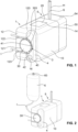
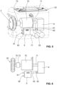
- the inner workings of the pump unit housing 1 is shown schematically in the Figures 3 and 4 shown.
- a drive train 7 with a drive in the form of a motor 70 is accommodated inside the pump unit housing 1.
- the motor 70 which is preferably a brushless direct current motor, is used to drive the peristaltic pump 3 and the vacuum pump, which is designed here as a membrane pump 8.
- the stator of the motor 70 is attached to the pump unit housing 1 in a rotationally fixed manner by means of a fastening plate 700.
- the motor 70 has a rotor which is connected to a motor shaft 71 in a rotationally fixed manner. Due to the direction of rotation of the rotor of the motor 70, an axis of rotation of the drive train 7 is defined.
- the motor shaft 71 whose longitudinal central axis coincides with the axis of rotation, projects out of the motor 70 with its two end regions on both sides.
- a first freewheel 72 By means of a first freewheel 72, the first end region of the motor shaft 71 is connected to a first drive shaft 74, and by means of a second freewheel 73, the second end region of the motor shaft is connected to a second drive shaft 75.
- the freewheels 72 and 73 represent clutches which only act in one direction of rotation, ie the rotational movement of the motor shaft 71 is only transmitted to the first or second drive shaft 74, 75 when the motor shaft 71 rotates in a certain direction. However, if the rotational speed of the drive shaft 74 or 75 is already greater than that of the motor shaft 71, no torque transmission takes place in the corresponding freewheel 72 or 73.
- the freewheels 72 and 73 can therefore also referred to as overrunning clutches.
- the first drive shaft 74 and the second drive shaft 75 extend with their respective longitudinal center axes along the axis of rotation of the drive train 7.
- the directions of rotation in which torque is transmitted from the motor shaft to the first and second drive shafts 74, 75, respectively, are for the two freewheels 72 and 73 oriented in reverse directions.
- the motor shaft 71 rotates counterclockwise, only torque is transmitted to the first drive shaft 74, while the second drive shaft 75 is stationary. In this case, only the membrane pump 8 is driven, but not the peristaltic pump 3.
- the peristaltic pump 3 is driven, but not the diaphragm pump 8.
- the drive train 7 is thus formed by the motor 70, the motor shaft 71, the two freewheels 72 and 73 as well as by the first drive shaft 74 and the second drive shaft 75. Due to the two freewheels 72 and 73 oriented in opposite directions, this embodiment ensures that only one of the two pumps 3 and 8 is in operation in any case. Depending on the direction of rotation of the motor 70, either the peristaltic pump 3 or the membrane pump 8 is driven.
- the membrane pump 8 serves to generate a vacuum in the fluid collection container 5 in order to suck in body fluids via the secretion line S and collect them in the fluid collection container.
- the membrane pump 8 has a vacuum connection 81, which can be connected to the container-side vacuum connection of the fluid collection container 5 via a line not shown in the figures.
- the membrane pump 8 has an outlet 82 in order to expel the sucked in air through it.
- the outlet 82 is connected to a line, not shown in the figures, which opens into the environment, i.e. to the outside.
- the diaphragm pump 8 is driven via the first drive shaft 74.
- the peristaltic pump 3 has, as already mentioned, several pressure rollers 303. These pressure rollers 303 are freely rotatable about their respective axes Pump head 30 is mounted and arranged between two circular plates 301 and 302 which extend parallel to one another. The axes of the pressure rollers 303 connect the two plates 301 and 302 with each other. The pump head 30 can be set into a rotational movement about the axis of rotation of the drive train 7 via the second drive shaft 75.
- An electronics unit 2 is also housed inside the pump unit housing 1.
- the electronics unit 2 has a printed circuit board (PCB) 22, on which electronic components 21, such as in particular a control unit, a motor output stage, pressure measurement sensors, a memory chip, etc., are arranged.
- a display and operating elements, possibly a touchscreen, are also arranged on the PCB 22 to form the display and control panel 20.
- the electronic unit 2 is used in particular to set and regulate the direction of rotation and the speed of rotation of the motor 70, depending on the entries made by the user on the display and control panel 20.
- an energy storage device in the form of an accumulator 77 is also housed inside the pump unit housing 1.
- a pneumatic valve 9 is connected to the vacuum connection 81 of the membrane pump 8 via a connecting line 93.
- the pneumatic valve 9 has a vacuum connection 91, which is connected to the container-side vacuum connection of the fluid collection container 5 via a line not shown in the figures.
- the pneumatic valve also has an inlet 92, which opens into the environment via another line, also not shown.
- the entire suction power generated by the diaphragm pump 8 or only part of it is present at the vacuum connection 91.
- the pneumatic valve 9 can even be set in such a way that the connecting line 93 is connected directly to the inlet 92, so that atmospheric pressure prevails in the fluid collection container 5 and thus in the secretion line S despite the operation of the membrane pump 8. With such a valve position, instillation fluid can be supplied through the instillation line I without suction through the secretion line S at the same time.
- the position of the pneumatic valve 9 can preferably be regulated by the electronic unit 2, depending on the entries made by the user on the display and control panel 20.
- a third embodiment not according to the invention is shown in the Figures 7 to 9 shown.
- the device of this embodiment has one in the Figure 7 shown pump unit housing 1 'on which one in the Figures 8 and 9 fluid collection container 5 'shown can be connected.
- the pump unit housing 1 ' has an overall essentially cuboid shape with an in Figure 7 front wall, not shown, a rear wall 11', a first side wall 12' and a second side wall 13' as well as an upper wall 14' and a lower wall 15'.
- the front wall and the rear wall 11' each have a wall edge which protrudes from the first side wall 12' arranged between them.
- the fluid collection container 5' is held between these wall edges and can therefore be easily, but still securely and protected, attached to the pump unit housing 1'.
- receiving hooks 190' are provided on the pump unit housing 1', into which correspondingly designed and arranged pins 554' of the fluid collection container 5' can engage.
- the fluid collection container 5' is secured to the pump unit housing 1' by means of a retaining lug 191' attached to a spring-loaded element, which is designed to snap into a locking notch 553' formed on the fluid collection container 5'.
- the spring-loaded element to which the retaining lug 191' is attached can be pressed downwards against the spring force.
- the protruding wall edges of the front wall and the rear wall 11' as well as the receiving hooks 190' and the retaining lug 191' together form a container receptacle 19' of the fluid collection container 5'.
- the pump unit housing 1' has a housing-side vacuum connection 17', which is coupled to a container-side vacuum connection 551' provided on the fluid collection container 5' when the fluid collection container 5' is attached to the pump unit housing 1', so that via the connections 17' and 551' in A vacuum can be generated inside the fluid collection container 5 '.
- An adapter receptacle 18' is also provided within the first side wall 12', which serves to accommodate a hose adapter not shown in the figures.
- the hose adapter connects a secretion line, not shown in the figures, to the interior of the fluid collection container 5' via a container-side secretion connection 552' provided on the fluid collection container 5'.
- the motor 70' can here also be, in particular, a brushless direct current motor.
- the motor shaft 71 ' drives a first end region directly in the Figure 7 Diaphragm pump not shown for representational reasons. With a second one End area, which is in the Figure 7 is not visible, the motor shaft 71' is connected to a freewheel 72', which connects the motor shaft 71' to a drive shaft 75'.
- the drive shaft 75' which extends along the axis of rotation of the motor shaft 71', protrudes through the first side wall 12'.
- a coupling element 76' is attached to the end of the drive shaft 75' in a rotationally fixed manner.
- the coupling element 76' has the shape of a gear. In this case it is a gear with four teeth.
- a pump head 30' of a peristaltic pump 3' integrated in the fluid collection container 5' can be driven via the coupling element 76' if the fluid collection container 5' is attached to the pump unit housing 1' as intended.
- the pump head 30 ' is not integrated in a fluid collection container, but on any other part, such as an intermediate part, which can be coupled between the pump unit housing 1' and a fluid collection container.
- the pump head 30' could in particular also represent part of a container in which the instillation substance is held.
- the container could have an identification feature and the device an identification unit to identify what type of substance is contained in the container.
- the device could then be designed to select one of several possible operating modes for driving the first pump and the second pump or the coupling element depending on the identified type of substance or to limit the selection of operating modes for the user depending on the substance.
- the identification feature can in particular be readable electronically, for example using RFID. Such identification and subsequent preselection of operating modes is of course also conceivable if the pump head is not integrated in the container with the substance to be identified.
- the fluid collection container 5' has a front wall 50', a rear wall which is not visible in the figures, two side walls 52' and 53' as well as an upper wall 54 and a lower wall which is also not visible. These walls are formed by a base part 55' made of an opaque material and a transparent part 56'. At A filling level scale 560' is provided on the side wall 52', which is formed exclusively by the transparent part 56'.
- That side wall 53' which is formed exclusively by the base part 55', has a centrally arranged, annular recess 555'. Within the annular recess 555', the side wall 53' forms a concentrically arranged bearing pin 556', which has an upper recess 557' which is open towards the top.
- a ring gear 57' is accommodated in the annular recess 555', which is freely rotatable around the bearing pin 556'.
- pressure rollers (not visible in the figures) are mounted so that they can rotate freely at regular intervals along the circumferential direction.
- the pressure rollers are used to roll onto a hose inserted in the annular recess 555' on the radial outside of the ring gear 57'.
- the hose can in particular form an instillation line I. As the pressure rollers roll on the hose, it is compressed and the fluid in it is transported.
- a circumferential toothing 570' is formed on the ring gear 57' on its radial inside.
- the toothing 570' comes into engagement with the coupling element 76', so that when the drive shaft 75' rotates, the rotational movement is transmitted to the ring gear 57' via the coupling element 76'.
- the ring gear 57' together with the annular recess 555' and the instillation line I inserted therein, thus forms a peristaltic pump 3', with the ring gear 57' forming the pump head 30'.
- corresponding guide channels for receiving the instillation line I are formed within the first side wall 12', which run in a straight line and parallel to one another from the annular recess 555' upwards to the upper Wall 54 'run.
- the fluid collection container 5 ' Essentially all parts of the fluid collection container 5 ', including the ring gear 57 ' and the pressure rollers attached to it, are advantageous Injection molding process manufactured. Since the fluid collection container 5 'usually represents a disposable part, which is often replaced and disposed of after a single use, the requirements for the pump head 30 integrated therein are relatively low. The manufacturing costs for the entire device can thereby be significantly reduced compared to a device in which the pump head is arranged in or on the pump unit housing and must therefore be designed for a much longer service life.
- the drive train 7 or 7' can also have one or more gears in order to change the rotational speed of the pump head 30 and/or the pumping frequency of the diaphragm pump 8 compared to that of the motor 70.
- the peristaltic pump 3, 3 'and the diaphragm pump 8 although they have a common drive in the form of the motor 70 or 70', can be operated at any different or the same pump frequencies.
- the gearbox(es) can, but does not have to, be combined with the freewheels 72, 72' and/or 73. They can therefore be provided in addition to or as an alternative to the freewheels 72, 72' and 73.
- the invention described here is not limited to the embodiments mentioned and a variety of modifications are possible.
- the first and second pumps do not necessarily have to be in the form of a membrane pump and a peristaltic pump; instead, depending on the application, any type of pump can be used for both pumps.
- the embodiments mentioned preferably relate to devices which are each designed to be portable, so that they can be easily carried by the user alone and without excessive effort. In principle, the devices described can be dimensioned as desired. A variety of other modifications are conceivable.
Landscapes
- Health & Medical Sciences (AREA)
- Engineering & Computer Science (AREA)
- Heart & Thoracic Surgery (AREA)
- Animal Behavior & Ethology (AREA)
- General Health & Medical Sciences (AREA)
- Vascular Medicine (AREA)
- Veterinary Medicine (AREA)
- Biomedical Technology (AREA)
- Public Health (AREA)
- Life Sciences & Earth Sciences (AREA)
- Hematology (AREA)
- Anesthesiology (AREA)
- Mechanical Engineering (AREA)
- General Engineering & Computer Science (AREA)
- Pulmonology (AREA)
- Ophthalmology & Optometry (AREA)
- Nuclear Medicine, Radiotherapy & Molecular Imaging (AREA)
- Surgery (AREA)
- Reciprocating Pumps (AREA)
- External Artificial Organs (AREA)
- Infusion, Injection, And Reservoir Apparatuses (AREA)
Description
- Die vorliegende Erfindung betrifft eine Vorrichtung zum Absaugen von Körperfluiden und zum Zuführen einer Substanz zu einem menschlichen oder tierischen Körper. Derartige Vorrichtungen werden insbesondere im medizinischen Bereich verwendet, beispielsweise in der mit Instillation oder Irrigation kombinierten Unterdruck-Wundtherapie, in der Augenchirurgie oder bei der Fettabsaugung.
- Im medizinischen Bereich gibt es vielfältige Anwendungen, bei denen einerseits Körperfluide oder Sekrete aus Körperkavitäten oder Wunden mittels einer Pumpe abgesaugt und andererseits eine Substanz dem Körper zugeführt werden. Mögliche Anwendungsgebiete betreffen insbesondere die mit Instillation kombinierte Unterdruck-Wundtherapie, die Augenchirurgie und die Liposuktion (Fettabsaugung). Je nach Anwendung erfolgen die Absaugung und die Zuführung dabei gleichzeitig, nacheinander und/oder abwechslungsweise intermittierend.
- Bei der zuzuführenden Substanz kann es sich beispielsweise um eine physiologische oder nicht physiologische Kochsalzlösung, ein Arzneimittel oder um ein Gemisch davon handeln. Die Substanz kann zum Beispiel zur Förderung der Wundheilung, zur Verhinderung von Infektionen oder zur lokalen Anästhesie dienen. Das Zuführen der Substanz kann somit zur Spülung oder therapeutischen, diagnostischen und/oder präventiven Zwecken dienen.
- Oft wird zum Zuführen der Substanz ähnlich wie bei der herkömmlichen Infusion ein mit der zuzuführenden Substanz gefüllter Flüssigkeitsbeutel oder eine Flasche erhöht über der zu behandelnden Körperstelle angeordnet, so dass die Substanz aufgrund des hydrostatischen Druckes durch eine Zuführleitung der zu behandelnden Stelle zugeführt wird. Separat dazu werden die Körperfluide von einer Vakuumpumpe via einer entsprechenden Leitung abgesaugt.
- Um eine bessere Einstellung und Regelung beim Zuführen der Substanz zu ermöglichen, und/oder um unabhängig von der Anordnung und insbesondere der Höhenlage des mit der Substanz gefüllten Flüssigkeitsbehälters zu sein, sind auch Systeme hinlänglich bekannt, bei denen die Zuführung der Substanz zum Körper mittels einer Pumpe, insbesondere einer sog. Peristaltik- oder Schlauchpumpe erfolgt.
- Beispielsweise zeigt die
WO 2016/054470 eine derartige Vorrichtung mit einer ersten Pumpe zum Zuführen von Substanzen zu einem Wundbereich und mit einer zweiten Pumpe zum Absaugen von Fluiden aus dem Wundbereich. - Die Bedienung derartiger Vorrichtungen ist für den Anwender oft umständlich, da einerseits die Pumpe zum Zuführen der Substanzen und andererseits die Pumpe zum Absaugen korrekt installiert und eingestellt werden müssen.
- Um den apparativen Aufwand bei der Behandlung zu verringern, sind Geräte bekannt, bei denen die Pumpe für das Absaugen der Körperfluide sowie die Pumpe für das Zuführen der Substanz in einem gemeinsamen Gehäuse untergebracht sind.
- Beispielsweise offenbart die
WO 2015/091070 ebenso wie dieUS 2008/0154184 , dieUS 2008/0154182 , dieUS 8,591,453 und dieUS 2008/0154185 ein Gerät mit zwei in einem gemeinsamen Gehäuse angeordneten Pumpen, von denen eine zum Absaugen von Körperfluiden und die andere zum Zuführen einer Substanz dient. - Auch in der
US 2014/0163487 ist ein derartiges Gerät mit zwei Pumpen offenbart, wobei hier der Pumpenkopf einer Peristaltikpumpe, welche zum Zuführen einer Substanz zum Körper dient, auf der Aussenseite des Pumpaggregatgehäuses angeordnet ist. Ein Flüssigkeitsbehälter, welcher zur Aufnahme einer Instillationsflüssigkeit dient, ist an das Pumpaggregatgehäuse anschliessbar. Am Flüssigkeitsbehälter ist eine Schlauchführung ausgebildet, aufgrund welcher der Pumpenkopf, wenn der Behälter am Pumpaggregatgehäuse angeschlossen ist, eine entsprechende Pumpwirkung auf den aus dem Behälterinneren herausführenden Instillationsschlauch ausübt, um so die Instillationsflüssigkeit zum Körper hin zu pumpen. - Diese Vorrichtungen, welche einerseits zum Absaugen von Körperfluiden sowie andererseits zum Zuführen einer Substanz dienen, haben meist ein beträchtliches Volumen sowie Gewicht. Ausserdem sind sie aufwändig und entsprechend kostenintensiv in der Herstellung.
- Weitere gattungsgemässe Vorrichtungen sind zum Beispiel in der
EP 2 883 555 , derCN 104771801 , derUS 4,634,024 offenbart. -
US 2006/025727 A1 ,US 2013/085462 A1 ,DE 20 2015 006341 U1 undFR 2 960 423 A1 - Es ist deshalb eine Aufgabe der Erfindung, eine vielseitig einsetzbare Vorrichtung zum Absaugen von Körperfluiden und zum Zuführen einer Substanz zu einem menschlichen oder tierischen Körper zu schaffen, welche ein geringes Volumen und Gewicht aufweist. Die Vorrichtung sollte ausserdem für den Anwender einfach handhabbar sein.
- Zur Lösung dieser Aufgabe wird eine Vorrichtung vorgeschlagen, wie sie in Anspruch 1 angegeben ist. Vorteilhafte Ausgestaltungen der Erfindung sind in den abhängigen Ansprüchen angegeben. Die vorliegende Erfindung stellt also eine Vorrichtung zum Absaugen von Körperfluiden und zum Zuführen einer Substanz zu einem menschlichen oder tierischen Körper zur Verfügung, aufweisend
- eine erste Pumpe zum Absaugen der Körperfluide;
- eine zweite Pumpe, um mittels der zweiten Pumpe die Substanz zum Körper zu befördern; sowie
- einen Antrieb zum Antreiben der ersten Pumpe; wobei derselbe Antrieb, welcher zum Antreiben der ersten Pumpe dient, auch zum Antreiben der zweiten Pumpe dient,
- dadurch gekennzeichnet, dass die Vorrichtung ausserdem zumindest einen ersten Freilauf aufweist, mittels welchem die erste Pumpe oder die zweite Pumpe an den Antrieb gekoppelt ist, wobei es sich bei der ersten Pumpe um eine Vakuumpumpe handelt, und wobei die Vorrichtung zusätzlich ein Ventil aufweist, mittels welchem die Vakuumpumpe mit der Umgebung verbindbar ist, um zumindest teilweise anstatt Körperfluide Luft aus der Umgebung anzusaugen.
- Indem derselbe Antrieb zum Antreiben, insbesondere zum gleichzeitigen Antreiben, von beiden Pumpen dient, kann die Vorrichtung insgesamt kleiner dimensioniert werden und zudem ein geringeres Gewicht aufweisen. Die Vorrichtung kann dadurch insbesondere derart ausgebildet werden, dass sie tragbar ist, das heisst, dass sie von einem Benutzer alleine und ohne übermässigen Kraftaufwand bequem getragen werden kann. Vorteilhaft weist die Vorrichtung zudem eine insgesamt kompakte Bauweise auf. Aufgrund des nur einen Antriebs ist auch die Fehleranfälligkeit verringert, und die Vorrichtung ist insgesamt kostengünstiger herstellbar.
- Bei der ersten Pumpe handelt es sich erfindungsgemäß um eine Vakuumpumpe, insbesondere um eine Membranpumpe. Eine Membranpumpe weist in der Regel zumindest eine Membran sowie eine von dieser begrenzte Pumpkammer auf. Die Vorrichtung weist zusätzlich ein Ventil, insbesondere ein Pneumatikventil, auf, mittels welchem die Vakuumpumpe mit der Umgebung verbindbar ist, um zumindest teilweise oder sogar vollständig anstatt Körperfluide Luft aus der Umgebung anzusaugen. Das Ventil kann insbesondere mit einem Vakuumanschluss der Vakuumpumpe verbunden sein, an welchen eine Saugleitung anschliessbar ist. Mittels Umstellen des Ventils kann der Vakuumanschluss bei Bedarf zumindest teilweise oder sogar vollständig statt mit der Saugleitung mit der Umgebung verbunden werden. Das Ventil ermöglicht es, die Saugleistung zum Absaugen der Körperfluide bei gleichbleibender Motorleistung zu variieren.
- Bei der zweiten Pumpe handelt es sich bevorzugt um eine Peristaltikpumpe. Peristaltikpumpen sind auch unter dem Begriff Schlauchpumpen bekannt und eignen sich besonders gut für eine pulsierende Zuführung einer Substanz, insbesondere einer fluiden Substanz wie einer Flüssigkeit, zum Körper. Eine Peristaltikpumpe weist in der Regel zumindest einen drehbar gelagerten Pumpenkopf auf, an welchem zum Beispiel Anpressrollen oder Gleitschuhe angebracht sind.
- Die erfindungsgemässe Vorrichtung wird für medizinische Zwecke eingesetzt, insbesondere zu der mit Instillation oder Irrigation kombinierten Unterdruckbehandlung von Wunden am menschlichen oder tierischen Körper. Andere Anwendungsgebiete sind jedoch möglich, beispielsweise die kombinierte Fettabsaugung und Spülung bei der Liposuktion oder das Spülen von Kathetern zur Vermeidung von Verstopfungen oder die kombinierte Absaugung und Spülung bei der Augenchirurgie. Der Freilauf kann insbesondere bewirken, dass je nach Drehrichtung des Antriebs entweder beide Pumpen zusammen angetrieben werden, oder dass nur die erste Pumpe bzw. nur die zweite Pumpe angetrieben wird. Dies kann für bestimmte Anwendungen erwünscht sein.
- Der erste Freilauf kann zum Beispiel die erste Pumpe an den Antrieb koppeln. Vorzugsweise ist dann ein zweiter Freilauf vorhanden, mittels welchem die zweite Pumpe entweder beide Pumpen zusammen angetrieben werden, oder dass nur die erste Pumpe bzw. nur die zweite Pumpe angetrieben wird. Dies kann für bestimmte Anwendungen erwünscht sein.
- Der erste Freilauf kann zum Beispiel die erste Pumpe an den Antrieb koppeln. Vorzugsweise ist dann ein zweiter Freilauf vorhanden, mittels welchem die zweite Pumpe an den Antrieb gekoppelt ist. Der zweite Freilauf weist vorteilhaft eine im Vergleich zum ersten Freilauf entgegengesetzte Freilaufrichtung auf. Es kann dadurch insbesondere sichergestellt werden, dass je nach Drehrichtung des Antriebs entweder die erste Pumpe oder die zweite Pumpe angetrieben wird, nicht jedoch beide zusammen. Das heisst, entweder wird eine Substanz zum Körper zugeführt, oder es werden Körperflüssigkeiten abgesaugt, jedoch nicht beides gleichzeitig.
- Beim ersten und, falls vorhanden, zweiten Freilauf kann es sich beispielsweise um einen Klemmkörper-Freilauf, um eine Schlingfederkupplung (Federwickel-Freilauf) oder um eine selbstsynchronisierende Schaltkupplung handeln.
- Beim Antrieb handelt es sich in der Regel um einen Motor, insbesondere um einen Elektromotor. In einer insbesondere bevorzugten Ausführungsform handelt es sich um einen bürstenlosen Gleichstrommotor, da ein solcher in der Regel bei tiefen Drehzahlen von weniger als 100U/min betrieben werden kann. Ein bürstenloser Gleichstrommotor lässt zudem eine Druckregelung mit relativ kleiner Amplitude zu, wodurch eine sehr genaue Steuerung des Druckes (Unterdruck oder Überdruck) möglich wird.
- Die Vorrichtung weist vorteilhaft ein Pumpaggregatgehäuse auf mit einem Innenraum, in welchem zumindest die erste Pumpe und der Antrieb untergebracht sind. Die zweite Pumpe kann ebenfalls im Innenraum des Pumpaggregatgehäuses angeordnet sein. Vorzugsweise ist jedoch entweder die zweite Pumpe auf einer Aussenseite des Pumpaggregatgehäuses angeordnet.
- Eine einfache Ausführungsform ergibt sich insbesondere dann, wenn die Vorrichtung einen Antriebsstrang aufweist, bei welchem der Antrieb zwischen der ersten Pumpe und der zweiten Pumpe angeordnet ist.
- Um eine besonders vielseitige Einsetzbarkeit der Vorrichtung zu ermöglichen, ist diese vorteilhaft derart ausgebildet, dass die Pumpleistung der ersten Pumpe einerseits und die Pumpleistung der zweiten Pumpe andererseits unabhängig voneinander einstellbar sind. Die Einstellbarkeit bezieht sich hier weniger auf die Herstellung, als vielmehr auf die Verwendung der fertig hergestellten Vorrichtung. Die unabhängige Einstellbarkeit der Pumpleistungen der ersten und der zweiten Pumpe kann auf verschiedene Arten und Weisen erreicht werden. So kann dies zum Beispiel mittels einem oder mehreren Freiläufen in Kombination mit einem an einer Vakuumpumpe angeschlossenem Ventil erreicht werden. Auch die Verwendung von Getrieben in Kombination mit zum Beispiel einem Freilauf ist möglich. Weitere Möglichkeiten sind denkbar.
- In bestimmten Ausführungsformen kann somit ein Antriebsstrang mit zumindest einem Getriebe vorgesehen sein, mittels welchem der Antrieb an die ersten Pumpe oder an die zweite Pumpe gekoppelt ist. Die erste bzw. zweite Pumpe kann aufgrund des Getriebes mit einer im Vergleich zum Antrieb unterschiedlichen Drehzahl angetrieben werden.
- In einer bestimmten Ausführungsform ist ein Behälter mit der zuzuführenden Substanz an die Vorrichtung anbringbar. Der Behälter kann ein Identifikationsmerkmal und die Vorrichtung eine Identifikationseinheit aufweisen, um zu identifizieren, welche Art einer Substanz im Behälter enthalten ist. Die Vorrichtung kann dann insbesondere dazu ausgebildet sein, in Abhängigkeit der identifizierten Art der Substanz einen von mehreren möglichen Betriebsmodi zum Antreiben der ersten Pumpe und der zweiten Pumpe auszuwählen oder vorauszuwählen.
- In den Zeichnungen zeigen:
- Fig. 1
- eine perspektivische Ansicht einer schematisch gezeigten Vorrichtung gemäss einer ersten erfindungsgemässen Ausführungsform;
- Fig. 2
- eine perspektivische Ansicht der Vorrichtung der
Fig. 1 , verbunden mit einem Flüssigkeitsbehälter mit Instillationsflüssigkeit; - Fig. 3
- eine perspektivische Ansicht der Vorrichtung der
Fig. 1 , wobei das Pumpaggregatgehäuse nur mit gestrichelten Linien angedeutet ist; - Fig. 4
- eine Draufsicht auf den Antriebsstrang, den Pumpenkopf der peristaltischen Pumpe und die Membranpumpe der Vorrichtung der
Fig. 1 ; - Fig. 5
- eine perspektivische Ansicht einer schematisch gezeigten Vorrichtung gemäss einer zweiten erfindungsgemässen Ausführungsform, wobei das Pumpaggregatgehäuse nur mit gestrichelten Linien angedeutet ist;
- Fig. 6
- eine Draufsicht auf den Antriebsstrang, den Pumpenkopf der peristaltischen Pumpe, die Membranpumpe und das Pneumatikventil der Vorrichtung der
Fig. 1 ; - Fig. 7
- eine perspektivische Ansicht einer schematisch gezeigten Vorrichtung gemäss einer nicht erfindungsgemässen Ausführungsform, wobei die Vorderwand des Pumpaggregatgehäuses weggelassen ist;
- Fig. 8
- eine erste perspektivische Ansicht eines Fluidsammelbehälters, der zum Anschliessen an die Vorrichtung der
Fig. 7 geeignet ist; sowie - Fig. 9
- eine zweite perspektivische Ansicht des Fluidsammelbehälters der
Fig. 8 . - In den
Figuren 1 bis 7 sind unterschiedliche Ausführungsformen von Vorrichtungen gezeigt, wobei sich dieFiguren 1 bis 4 auf eine erste erfindungsgemässe Ausführungsform, dieFiguren 5 und 6 auf eine zweite erfindungsgemässe Ausführungsform und dieFigur 7 auf eine dritte nicht erfindungsgemässe Ausführungsform beziehen. DieFiguren 8 und 9 zeigen einen Fluidsammelbehälter 5', der an die in derFigur 7 gezeigte Vorrichtung anschliessbar ist. - Die in den
Figuren 1 bis 7 gezeigten Vorrichtungen sind insbesondere zur kombinierten Unterdruck- und Instillations-/Irrigationsbehandlung von Wunden am menschlichen oder tierischen Körper geeignet. Dementsprechend beziehen sich die nachfolgenden Erläuterungen jeweils auf die Verwendung der Vorrichtungen in der kombinierten Unterdruck- und Instillations-/Irrigationsbehandlung. Es wäre grundsätzlich aber auch möglich, diese Vorrichtungen, bei entsprechend angepasster Auslegung, für die Katheterspülung, die Augenchirurgie, die Fettabsaugung oder eine andere medizinische Anwendung zu verwenden. - Elemente mit einer identischen oder ähnlichen technischen Funktion und Wirkung sind in den
Figuren 1 bis 9 bei den verschiedenen Ausführungsformen jeweils mit denselben Bezugszeichen versehen oder weisen dasselbe, jedoch mit einem Strich (`) versehene Bezugszeichen auf. - Wie es in der
Figur 1 gut erkennbar ist, weist die Vorrichtung der ersten erfindungsgemässen Ausführungsform derFiguren 1 bis 4 ein Pumpaggregatgehäuse 1 mit einem daran anschliessbaren Fluidsammelbehälter 5 auf. - Das Pumpaggregatgehäuse 1 weist eine insgesamt im Wesentlichen quaderförmige Gestalt auf. In den
Figuren 1 und 2 sind jeweils eine obere Wand 14, eine Vorderwand 10 sowie eine Seitenwand 12 des Pumpaggregatgehäuses 1 erkennbar. Die Seitenwand 12 weist in ihrem Eckbereich, wo sie mit der Vorderwand 10 verbunden ist, eine Einbuchtung 120 auf, welche sich entlang der gesamten Höhe der Seitenwand 12 erstreckt. - Der Fluidsammelbehälter 5 weist ebenfalls eine insgesamt im Wesentlichen quaderförmige Gestalt auf. In den
Figuren 1 und 2 sind jeweils eine obere Wand 54 sowie eine Vorderwand 50 zu erkennen. Wenn der Fluidsammelbehälter 5 bestimmungsgemäss am Pumpaggregatgehäuse 1 angeschlossen ist, wie es in denFiguren 1 und 2 gezeigt ist, bildet er zusammen mit diesem eine insgesamt im Wesentlichen quaderförmige Form mit abgerundeten Aussenkanten und -ecken. Die Aussenwände des Pumpaggregatgehäuses 1 und des Fluidsammelbehälters 5 sind dabei jeweils fluchtend zueinander angeordnet. - Durch die obere Wand 54 hindurch führen zwei Schläuche aus dem Fluidsammelbehälter 5 heraus, von denen einer eine Sekretleitung S und der andere eine Hilfsleitung H bildet. Die Sekretleitung S dient dazu, den Fluidsammelbehälter 5 mit einer Kavität oder Wunde eines Patienten zu verbinden, aus welcher Körperfluide abgesaugt werden sollen, wobei die abgesaugten Körperfluide im Fluidsammelbehälter 5 gesammelt werden. Mittels der Hilfsleitung H ist es möglich, bei Bedarf die Sekretleitung S zu spülen und/oder den Druck oder die Durchflussmenge in der Sekretleitung S zu messen. Die Hilfsleitung H mündet hierzu bevorzugt in der Nähe der Kavität bzw. Wunde in die Sekretleitung S.
- Die Sekretleitung S mündet mit ihrem patientenfernen Ende in das Innere des Fluidsammelbehälters 5. In seiner dem Pumpaggregatgehäuse 1 zugewandten Seitenwand weist der Fluidsammelbehälter 5 einen in den Figuren nicht erkennbaren Vakuumanschluss auf, welcher eine im Pumpaggregatgehäuse 1 angeordnete Vakuumpumpe mit dem Inneren des Fluidsammelbehälters 5 verbindet, so dass mittels der Vakuumpumpe im Inneren des Fluidsammelbehälters 5 ein Vakuum erzeugbar ist. Die Hilfsleitung H führt via den Fluidsammelbehälter 5 und einen in derselben Seitenwand wie der Vakuumanschluss angeordneten und in den Figuren ebenfalls nicht erkennbaren Hilfsanschluss direkt in das Pumpaggregatgehäuse 1.
- Die Seitenwand 12 des Pumpaggregatgehäuses 1 weist eine zentral angeordnete Vertiefung 121 auf. Die Vertiefung 121 hat die Gestalt einer Halbkreisfläche und ist zur Einbuchtung 120 hin offen ausgebildet. Die Vertiefung 121 weist dieselbe Tiefe wie die Einbuchtung 120 auf. Die Seitenwand 12 bildet ausserdem einen ersten Führungskanal 122 sowie einen zweiten Führungskanal 123 in Form von geradlinig und parallel zueinander angeordneten Vertiefungen. Die beiden Führungskanäle 123 münden am obersten bzw. am untersten Punkt der halbkreisflächenförmigen Vertiefung 121 jeweils tangential in diese hinein.
- Auf einen am unteren Bereich der Einbuchtung 120 der Seitenwand 12 vorgesehenen Aufsteckzapfen 16 ist ein Aufsteckteil 4 aufsetzbar, welches ungefähr dieselben Dimensionen wie die Einbuchtung 120 aufweist. Zur Aufnahme des Aufsteckzapfens 16 weist das Aufsteckteil 4 eine dazu komplementär ausgebildete Aussparung 40 auf. Der Aufsteckzapfen 16 kann insbesondere zum Einrasten in die Aussparung 40 ausgebildet sein. Weitere und/oder anders ausgebildete Befestigungsstrukturen zum Anbringen des Aufsteckteils 4 an das Pumpaggregatgehäuse 1 sind selbstverständlich denkbar.
- Das Aufsteckteil 4 weist eine seitlich zur Vertiefung 121 hin offene Ausnehmung 41 auf, welche die Gestalt einer Halbkreisfläche hat. Zusammen mit der Vertiefung 121 bildet die Ausnehmung 41, wenn das Aufsteckteil 4 bestimmungsgemäss am Pumpaggregatgehäuse 1 angebracht ist, eine kreisflächenförmige Vertiefung. Innerhalb dieser kreisflächenförmigen Vertiefung ist ein Pumpenkopf 30 einer Peristaltikpumpe 3 angeordnet.
- An der Peripherie des kreisförmigen Pumpenkopfes 3 sind in regelmässigen Abständen zueinander entlang der Umfangsrichtung mehrere Anpressrollen 303 frei drehbar angebracht. Der halbkreisbogenförmige Raum zwischen dem Pumpenkopf 3 und dem Aufsteckteil 4 bildet ein Schlauchbett 42. Das obere Ende dieses Schlauchbettes 42 mündet in den ersten Führungskanal 122 und das untere Ende in den zweiten Führungskanal 123. Mittels Abnehmen des Aufsteckteils 4 vom Pumpaggregatgehäuse 5 kann einfach ein Schlauch in die Führungskanäle 122 und 123 sowie das Schlauchbett 42 eingelegt bzw. daraus entnommen werden.
- Im Betrieb der Vorrichtung dreht sich der Pumpenkopf 3 um seine Längsmittelachse, so dass die Anpressrollen 303 auf einem in das Schlauchbett 42 eingelegten Schlauch abrollen. Dieser Schlauch bildet eine Instillationsleitung I und ist, wie es in der
Figur 1 gezeigt ist, in den ersten und den zweiten Führungskanal 122, 123 sowie das Schlauchbett 42 eingelegt. Im Bereich des Schlauchbetts 42 wird die Instillationsleitung I um 180° umgelenkt. Beim Abrollen pressen die Anpressrollen 303 den Schlauch jeweils gegen das Aufsteckteil 4, so dass eine in der Instillationsleitung I enthaltene fluide Substanz aufgrund der mechanischen Verformung des Schlauches durch diesen hindurchgedrückt und zum Wundbereich hin befördert wird. Die Peristaltikpumpe 3 wird somit insbesondere durch den Pumpenkopf 30, das Schlauchbett 42 und den entsprechend darin eingelegten Abschnitt der Instillationsleitung I gebildet. - Mit Hilfe der Peristaltikpumpe 3 wird durch die Instillationsleitung I hindurch eine fluide Substanz der Kavität oder Wunde des Patienten zugeführt. Bei der Substanz kann es sich beispielsweise um eine physiologische oder nicht physiologische Kochsalzlösung, ein Arzneimittel oder um ein Gemisch davon handeln. Die Instillationssubstanz kann zum Spülen einer Wunde oder Kavität dienen. Sie kann aber auch zum Einbringen eines Medikaments oder zur lokalen Betäubung des Wundbereichs dienen.
- Die Instillationsleitung I kann insbesondere, wie es in der
Figur 2 gezeigt ist, mit einem Flüssigkeitsbehälter 6 verbunden sein, in welchem eine Instillationsflüssigkeit gelagert ist. Der Flüssigkeitsbehälter 6, welcher hier als Beutel ausgebildet ist, weist einen Aufhänger 60 auf, um ihn zum Beispiel an einem Infusionsständer bzgl. der Schwerkraftrichtung oberhalb der Peristaltikpumpe 3 aufzuhängen. Auf diese Weise ist sichergestellt, dass jederzeit Instillationsflüssigkeit im Bereich der Peristaltikpumpe vorhanden ist. - Im Bereich der oberen Wand 14 des Pumpaggregatgehäuses 1 ist ein Anzeige- und Bedienfeld 20 angeordnet. Mit Hilfe des Anzeige- und Bedienfeldes 20 kann die Vorrichtung bedient, und es können insbesondere die Funktionen der Peristaltikpumpe 3 sowie der im Pumpaggregatgehäuse 1 untergebrachten Vakuumpumpe eingestellt werden. Ausserdem kann das Anzeige- und Bedienfeld 20 zum Anzeigen von Informationen zum Status der Vorrichtung, wie insbesondere aktuelle Pumpleistungen und -zyklen etc., dienen.
- Das Innenleben des Pumpaggregatgehäuses 1 ist schematisch in den
Figuren 3 und 4 gezeigt. Im Inneren des Pumpaggregatgehäuses 1 ist insbesondere ein Antriebsstrang 7 mit einem Antrieb in Form eines Motors 70 untergebracht. Der Motor 70, bei welchem es sich bevorzugt um einen bürstenlosen Gleichstrommotor handelt, dient zum Antreiben der Peristaltikpumpe 3 sowie der Vakuumpumpe, welche hier als Membranpumpe 8 ausgebildet ist. Mittels einer Befestigungsplatte 700 ist der Stator des Motors 70 drehfest am Pumpaggregatgehäuse 1 befestigt. - Der Motor 70 weist einen Rotor auf, der drehfest mit einer Motorwelle 71 verbunden ist. Aufgrund der Drehrichtung des Rotors des Motors 70 ist eine Rotationsachse des Antriebsstrangs 7 definiert. Die Motorwelle 71, deren Längsmittelachse mit der Rotationsachse zusammenfällt, ragt mit ihren beiden Endbereichen zu beiden Seiten hin aus dem Motor 70 heraus. Mittels eines ersten Freilaufs 72 ist der erste Endbereich der Motorwelle 71 mit einer ersten Antriebswelle 74 verbunden, und mittels eines zweiten Freilaufs 73 ist der zweite Endbereich der Motorwelle mit einer zweiten Antriebswelle 75 verbunden. Die Freiläufe 72 und 73 stellen Kupplungen dar, welche nur in einer Drehrichtung wirken, d.h. die Rotationsbewegung der Motorwelle 71 nur dann auf die erste bzw. zweite Antriebswelle 74, 75 übertragen, wenn sich die Motorwelle 71 in eine bestimmte Richtung dreht. Wenn die Drehgeschwindigkeit der Antriebswelle 74 bzw. 75 dabei aber bereits grösser ist als diejenige der Motorwelle 71 findet im entsprechenden Freilauf 72 bzw. 73 keine Drehmomentübertragung statt. Die Freiläufe 72 und 73 können daher auch als Überholkupplungen bezeichnet werden.
- Die erste Antriebswelle 74 und die zweite Antriebswelle 75 erstrecken sich mit ihren jeweiligen Längsmittelachsen entlang der Rotationsachse des Antriebsstranges 7. Die Drehrichtungen, in welche eine Drehmomentübertragung von der Motorwelle auf die erste bzw. zweite Antriebswelle 74, 75 stattfindet, sind für die beiden Freiläufe 72 und 73 in umgekehrte Richtungen orientiert. Bei einer Drehung der Motorwelle 71 im Gegenuhrzeigersinn erfolgt deshalb nur eine Drehmomentübertragung auf die erste Antriebswelle 74, während die zweite Antriebswelle 75 stillsteht. Es wird somit in diesem Fall nur die Membranpumpe 8, nicht jedoch die Peristaltikpumpe 3 angetrieben. Bei einer Umkehrung der Drehrichtung des Motors 70 und somit der Motorwelle 71 wird hingegen nur die Peristaltikpumpe 3, nicht aber die Membranpumpe 8 angetrieben.
- Der Antriebsstrang 7 wird im vorliegenden Ausführungsbeispiel somit durch den Motor 70, die Motorwelle 71, die beiden Freiläufe 72 und 73 sowie durch die erste Antriebswelle 74 und die zweite Antriebswelle 75 gebildet. Aufgrund der beiden in umgekehrte Richtungen orientierten Freiläufe 72 und 73 ist bei dieser Ausführungsform sichergestellt, dass in jedem Fall nur eine der beiden Pumpen 3 und 8 in Betrieb ist. Je nach Drehrichtung des Motors 70 wird entweder die Peristaltikpumpe 3 oder die Membranpumpe 8 angetrieben.
- Die Membranpumpe 8 dient dazu, im Fluidsammelbehälter 5 ein Vakuum zu generieren, um via die Sekretleitung S Körperfluide anzusaugen und im Fluidsammelbehälter zu sammeln. Dazu weist die Membranpumpe 8 einen Vakuumanschluss 81 auf, welcher via eine in den Figuren nicht gezeichnete Leitung mit dem behälterseitigen Vakuumanschluss des Fluidsammelbehälters 5 verbindbar ist. Ausserdem weist die Membranpumpe 8 einen Auslass 82 auf, um durch diesen hindurch die angesaugte Luft auszustossen. Der Auslass 82 ist hierzu mit einer in den Figuren nicht gezeigten Leitung verbunden, die in die Umgebung, d.h. nach aussen hin, mündet. Der Antrieb der Membranpumpe 8 erfolgt über die erste Antriebswelle 74.
- Die Peristaltikpumpe 3 weist, wie es bereits schon erwähnt wurde, mehrere Anpressrollen 303 auf. Diese Anpressrollen 303 sind um ihre jeweiligen Achsen frei drehbar an einem Pumpenkopf 30 gelagert und zwischen zwei sich parallel zueinander erstreckenden, kreisrunden Platten 301 und 302 angeordnet. Die Achsen der Anpressrollen 303 verbinden dabei jeweils die beiden Platten 301 und 302 miteinander. Der Pumpenkopf 30 ist über die zweite Antriebswelle 75 in eine Drehbewegung um die Rotationsachse des Antriebsstranges 7 versetzbar.
- Im Inneren des Pumpaggregatgehäuses 1 ist ausserdem eine Elektronikeinheit 2 untergebracht. Die Elektronikeinheit 2 weist eine Leiterplatine (engl. printed circuit board, PCB) 22 auf, auf welcher Elektronikkomponenten 21, wie insbesondere eine Steuereinheit, eine Motorendstufe, Druckmesssensorik, ein Speicherchip etc., angeordnet sind. Auf dem PCB 22 sind ausserdem ein Display und Bedienelemente, allenfalls ein Touchscreen, angeordnet, um das Anzeige- und Bedienfeld 20 zu bilden. Die Elektronikeinheit 2 dient insbesondere zum Einstellen und Regeln der Drehrichtung und der Drehgeschwindigkeit des Motors 70, in Abhängigkeit der vom Benutzer am Anzeige- und Bedienfeld 20 gemachten Eingaben.
- Zur Versorgung des Motors 70 sowie der Elektronikeinheit 2 mit elektrischer Energie ist ausserdem ein Energiespeicher in Form eines Akkumulators 77 im Inneren des Pumpaggregatgehäuses 1 untergebracht.
- Die in den
Figuren 5 und 6 gezeigte zweite erfindungsgemässe Ausführungsform ist bis auf einige wenige Unterschiede, welche nachfolgend erläutert werden, gleich ausgebildet wie die Ausführungsform derFiguren 1 bis 4 . - Im Gegensatz zur Ausführungsform der
Figuren 1 bis 4 weist diejenige derFiguren 5 und 6 nur einen einzigen Freilauf 73 auf, der die Motorwelle 71 mit derjenigen Antriebswelle 75 verbindet, welche den Pumpenkopf 30 antreibt. Der Antrieb der Membranpumpe 8 erfolgt direkt via die Motowelle 71. Es ist dadurch möglich, die beiden Pumpen 3 und 8 gleichzeitig anzutreiben, so dass zeitgleich eine Sekretabsaugung durch die Sekretleitung S als auch eine Zuführung von Instillationsflüssigkeit durch die Instillationsleitung I erfolgen kann. Bei einer Umkehrung der Drehrichtung des Motors 70 wird aufgrund des Freilaufs 73 aber nur die Membranpumpe 8 angetrieben. - Um beim zeitgleichen Betrieb der Membranpumpe 8 und der Peristaltikpumpe 3 aber dennoch eine beliebige Einstellung des im Fluidsammelbehälter 5 und in der Sekretleitung S herrschenden Vakuums zu ermöglichen, ist bei der vorliegenden Ausführungsform via eine Verbindungsleitung 93 ein Pneumatikventil 9 am Vakuumanschluss 81 der Membranpumpe 8 angeschlossen. Das Pneumatikventil 9 weist einen Vakuumanschluss 91 auf, welcher via eine in den Figuren nicht gezeichnete Leitung mit dem behälterseitigen Vakuumanschluss des Fluidsammelbehälters 5 verbunden ist. Ausserdem weist das Pneumatikventil einen Einlass 92 auf, welcher via eine weitere, ebenfalls nicht gezeigte Leitung, in die Umgebung mündet.
- Je nach Ventilstellung des Pneumatikventils 9 liegt am Vakuumanschluss 91 die gesamte von der Membranpumpe 8 erzeugte Saugleistung an oder nur ein Teil davon. Das Pneumatikventil 9 kann sogar derart eingestellt sein, dass die Verbindungsleitung 93 direkt mit dem Einlass 92 verbunden ist, so dass im Fluidsammelbehälter 5 und somit in der Sekretleitung S trotz des Betriebs der Membranpumpe 8 Atmosphärendruck herrscht. Bei einer derartigen Ventilstellung kann Instillationsflüssigkeit durch die Instillationsleitung I zugeführt werden, ohne dass gleichzeitig eine Absaugung durch die Sekretleitung S erfolgt. Die Stellung des Pneumatikventils 9 ist bevorzugt von der Elektronikeinheit 2, in Abhängigkeit der vom Benutzer am Anzeige- und Bedienfeld 20 gemachten Eingaben, regelbar.
- Eine dritte, nicht erfindungsgemässe Ausführungsform ist in den
Figuren 7 bis 9 gezeigt. Die Vorrichtung dieser Ausführungsform weist ein in derFigur 7 gezeigtes Pumpaggregatgehäuse 1' auf, an welches ein in denFiguren 8 und 9 gezeigter Fluidsammelbehälter 5' anschliessbar ist. - Das Pumpaggregatgehäuse 1' hat auch hier eine insgesamt im Wesentlichen quaderförmige Gestalt mit einer in der
Figur 7 nicht gezeigten Vorderwand, einer Rückwand 11', einer ersten Seitenwand 12' und einer zweiten Seitenwand 13' sowie einer oberen Wand 14' und einer unteren Wand 15'. Die Vorderwand und die Rückwand 11' weisen je eine Wandkante auf, welche der dazwischen angeordneten ersten Seitenwand 12' vorstehen. Der Fluidsammelbehälter 5' ist zwischen diesen Wandkanten gehalten und dadurch einfach, aber trotzdem sicher und geschützt an das Pumpaggregatgehäuse 1' befestigbar. - Zum Einhängen und Halten des Fluidsammelbehälters 5' am Pumpaggregatgehäuse 1' sind am Pumpaggregatgehäuse 1' Aufnahmehaken 190' vorgesehen, in welche entsprechend ausgebildete und angeordnete Zapfen 554` des Fluidsammelbehälters 5' eingreifen können. Mittels einer an einem federbelasteten Element angebrachten Rückhaltenase 191', welche zum Einschnappen in eine am Fluidsammelbehälter 5' ausgebildete Rastkerbe 553' ausgebildet ist, wird der Fluidsammelbehälter 5' am Pumpaggregatgehäuse 1' gesichert. Um die Rastverbindung zwischen der Rückhaltenase 191' und der Rastkerbe 553' zu lösen, kann das federbelastete Element, an welchem die Rückhaltenase 191' angebracht ist, entgegen der Federkraft nach unten gedrückt werden.
- Die vorstehenden Wandkanten der Vorderwand und der Rückwand 11' sowie die Aufnahmehaken 190' und die Rückhaltenase 191' bilden gemeinsam eine Behälteraufnahme 19` des Fluidsammelbehälters 5'.
- Das Pumpaggregatgehäuse 1' weist einen gehäuseseitigen Vakuumanschluss 17' auf, welcher beim Anbringen des Fluidsammelbehälters 5' an das Pumpaggregatgehäuse 1' an einen entsprechend am Fluidsammelbehälter 5' vorgesehenen behälterseitigen Vakuumanschluss 551' gekoppelt wird, so dass via die Anschlüsse 17` und 551' im Inneren des Fluidsammelbehälters 5' ein Vakuum erzeugbar ist.
- Innerhalb der ersten Seitenwand 12' ist ausserdem eine Adapteraufnahme 18' vorgesehen, welche zur Aufnahme eines in den Figuren nicht gezeigten Schlauchadapters dient. Der Schlauchadapter verbindet eine in den Figuren nicht gezeigte Sekretleitung via einen am Fluidsammelbehälter 5' vorgesehenen behälterseitigen Sekretanschluss 552' mit dem Inneren des Fluidsammelbehälters 5'.
- Im Inneren des Pumpaggregatgehäuses 1' ist ein Antriebsstrang 7' mit einem Motor 70` und einer mit dem Motor 70' verbundenen Motorwelle 71' untergebracht. Beim Motor 70' kann es sich auch hier insbesondere um einen bürstenlosen Gleichstrommotor handeln.
- Die Motorwelle 71' treibt mit einem ersten Endbereich direkt eine in der
Figur 7 aus darstellerischen Gründen nicht gezeigte Membranpumpe an. Mit einem zweiten Endbereich, welcher in derFigur 7 nicht sichtbar ist, ist die Motorwelle 71' mit einem Freilauf 72' verbunden, welcher die Motorwelle 71' mit einer Antriebswelle 75` verbindet. Die Antriebswelle 75`, welche sich entlang der Rotationsachse der Motorwelle 71' erstreckt, ragt durch die erste Seitenwand 12` hindurch. - Auf der Aussenseite des Pumpaggregatgehäuses 1' ist ein Kopplungselement 76` drehfest am Ende der Antriebswelle 75' angebracht. Das Kopplungselement 76' hat die Form eines Zahnrades. Im vorliegenden Fall ist es ein Zahnrad mit vier Zähnen. Via das Kopplungselement 76' kann ein im Fluidsammelbehälter 5` integrierter Pumpenkopf 30' einer Peristaltikpumpe 3' angetrieben werden, wenn der Fluidsammelbehälter 5' bestimmungsgemäss am Pumpaggregatgehäuse 1' angebracht ist.
- Grundsätzlich ist es natürlich auch denkbar, dass der Pumpenkopf 30' nicht in einem Fluidsammelbehälter integriert ist, sondern an einem beliebigen anderen Teil, wie beispielsweise einem Zwischenteil, welches zwischen dem Pumpaggregatgehäuse 1' und einem Fluidsammelbehälter angekoppelt werden kann. Der Pumpenkopf 30' könnte insbesondere auch einen Teil eines Behälters darstellen, in welchem die Instillationssubstanz aufgenommen ist. Der Behälter könnte ein Identifikationsmerkmal aufweisen und die Vorrichtung eine Identifikationseinheit, um zu identifizieren, welche Art einer Substanz im Behälter enthalten ist. Die Vorrichtung könnte dann dazu ausgebildet sein, in Abhängigkeit der identifizierten Art der Substanz einen von mehreren möglichen Betriebsmodi zum Antreiben der ersten Pumpe und der zweiten Pumpe bzw. des Kopplungselements auszuwählen oder die Auswahl der Betriebsmodi für den Benutzer in Abhängigkeit der Substanz zu beschränken. Das Identifikationsmerkmal kann insbesondere elektronisch auslesbar sein, zum Beispiel mittels RFID. Eine derartige Identifikation und anschliessende Vorauswahl von Betriebsmodi ist selbstverständlich auch dann denkbar, wenn der Pumpenkopf nicht im Behälter mit der zu identifizierenden Substanz integriert ist.
- Der Fluidsammelbehälter 5' weist eine Vorderwand 50`, eine in den Figuren nicht sichtbare Rückwand, zwei Seitenwände 52` und 53' sowie eine obere Wand 54 und eine ebenfalls nicht sichtbare untere Wand auf. Diese Wände werden durch ein aus einem opaken Material hergestellten Basisteil 55` und einem transparenten Teil 56' gebildet. An derjenigen Seitenwand 52`, welche ausschliesslich durch das transparente Teil 56` gebildet wird, ist eine Füllstandsskala 560' vorgesehen.
- Diejenige Seitenwand 53', welche ausschliesslich durch das Basisteil 55' gebildet wird, weist eine zentral angeordnete, ringförmige Vertiefung 555` auf. Innerhalb der ringförmigen Vertiefung 555` bildet die Seitenwand 53' einen konzentrisch angeordneten Lagerzapfen 556`, der eine obere, nach oben hin offene Aussparung 557` aufweist.
- In der ringförmigen Vertiefung 555` ist ein Hohlrad 57` aufgenommen, welches frei drehbar um den Lagerzapfen 556' herum angeordnet ist. Im Hohlrad 57' sind in den Figuren nicht sichtbare Anpressrollen in regelmässigen Abständen entlang der Umfangsrichtung frei drehbar angebracht. Die Anpressrollen dienen beim Drehen des Hohlrades 57' zum Abrollen auf einen in der ringförmigen Vertiefung 555` auf der radialen Aussenseite des Hohlrades 57` eingelegten Schlauch. Der Schlauch kann insbesondere eine Instillationsleitung I bilden. Indem die Anpressrollen auf dem Schlauch abrollen, wird dieser zusammengepresst und ein sich darin befindliches Fluid befördert.
- Auf seiner radialen Innenseite ist am Hohlrad 57` eine umlaufende Verzahnung 570` ausgebildet. Die Verzahnung 570' gerät beim bestimmungsgemässen Anbringen des Fluidsammelbehälters 5' an das Pumpaggregatgehäuse 1' in Eingriff mit dem Kopplungselement 76', so dass bei Drehen der Antriebswelle 75' die Drehbewegung via das Kopplungselement 76' auf das Hohlrad 57` übertragen wird.
- Das Hohlrad 57` bildet somit zusammen mit der ringförmigen Vertiefung 555` und der darin eingelegten Instillationsleitung I eine Peristaltikpumpe 3`, wobei das Hohlrad 57` den Pumpenkopf 30' bildet. Um die Instillationsleitung I zur ringförmigen Vertiefung 555' hin und wieder von dieser weg zu führen, sind innerhalb der ersten Seitenwand 12' entsprechende Führungskanäle zur Aufnahme der Instillationsleitung I ausgebildet, welche geradlinig und parallel zueinander von der ringförmigen Vertiefung 555' nach oben bis zur oberen Wand 54' verlaufen.
- Vorteilhaft werden im Wesentlichen sämtliche Teile des Fluidsammelbehälters 5', inklusive dem Hohlrad 57` und den daran angebrachten Anpressrollen, im Spritzgussverfahren hergestellt. Da der Fluidsammelbehälter 5' üblicherweise ein Wegwerfteil darstellt, welches oft bereits nach einer einzigen Anwendung ausgetauscht und entsorgt wird, sind die Anforderungen an den darin integrierten Pumpenkopf 30 verhältnismässig gering. Die Herstellungskosten für die gesamte Vorrichtung können dadurch erheblich gesenkt werden im Vergleich zu einer Vorrichtung, bei welcher der Pumpenkopf im oder am Pumpaggregatgehäuse angeordnet ist und dadurch für eine viel längere Lebensdauer ausgelegt sein muss.
- Bei allen Ausführungsformen kann der Antriebsstrang 7 bzw. 7` ausserdem eines oder mehrere Getriebe aufweisen, um die Drehgeschwindigkeit des Pumpenkopfes 30 und/oder die Pumpfrequenz der Membranpumpe 8 gegenüber derjenigen des Motors 70 zu verändern. Mittels des zumindest einen Getriebes können die Peristaltikpumpe 3, 3' und die Membranpumpe 8, obwohl sie einen gemeinsamen Antrieb in Form des Motors 70 bzw. 70` haben, beliebig mit unterschiedlichen oder gleichen Pumpfrequenzen betrieben werden. Das oder die Getriebe können, müssen aber nicht, mit den Freiläufen 72, 72` und/oder 73 kombiniert werde. Sie können somit zusätzlich oder alternativ zu den Freiläufen 72, 72` und 73 vorgesehen sein.
- Selbstverständlich ist die hier beschriebene Erfindung nicht auf die erwähnten Ausführungsformen beschränkt und eine Vielzahl von Abwandlungen ist möglich. So müssen die erste und die zweite Pumpe zum Beispiel nicht zwingend in Form einer Membranpumpe und einer Peristaltikpumpe vorliegen, sondern es können, je nach Anwendung, für beide Pumpen grundsätzlich beliebige Pumpenarten eingesetzt werden. Die erwähnten Ausführungsformen betreffen bevorzugt Vorrichtungen, welchen jeweils tragbar ausgebildet sind, so dass sie vom Benutzer alleine und ohne übermässigen Kraftaufwand bequem tragbar sind. Grundsätzlich lassen sich die beschriebenen Vorrichtungen beliebig dimensionieren. Eine Vielzahl weiterer Abwandlungen ist denkbar.
BEZUGSZEICHENLISTE 1, 1' Pumpaggregatgehäuse 40 Aussparung 10 Vorderwand 41 Ausnehmung 11' Rückwand 42 Schlauchbett 12, 12' Seitenwand 120 Einbuchtung 5, 5' Fluidsammelbehälter 121 Vertiefung 50, 50' Vorderwand 122 Erster Führungskanal 52` Seitenwand 123 Zweiter Führungskanal 53' Seitenwand 13' Seitenwand 54, 54' Obere Wand 14, 14' Obere Wand 55` Basisteil 15' Untere Wand 551' Behälterseitiger 16 Aufsteckzapfen Vakuumanschluss 17' Gehäuseseitiger Vakuumanschluss 552` Behälterseitiger Sekretanschluss 18' Adapteraufnahme 553` Rastkerbe 19' Behälteraufnahme 554' Zapfen 190` Aufnahmehaken 555` Ringförmige Vertiefung 191' Rückhaltenase 556` Lagerzapfen 557` Aussparung 2 Elektronikeinheit 56` Transparentes Teil 20 Anzeige- und Bedienfeld 560` Füllstandsskala 21 Elektronikkomponenten 57` Hohlrad 22 PCB 570` Verzahnung 3, 3' Peristaltikpumpe 6 Flüssigkeitsbehälter 30, 30' Pumpenkopf 60 Aufhänger 301 Platte 302 Platte 7, 7' Antriebsstrang 303 Anpressrollen 70, 70` Motor 700 Befestigungsplatte 4 Aufsteckteil 71, 71' Motorwelle 72, 72` Erster Freilauf 73 Zweiter Freilauf 9 Pneumatikventil 74 Erste Antriebswelle 91 Vakuumanschluss 75, 75` Zweite Antriebswelle 92 Einlass 76` Kopplungselement 93 Verbindungsleitung 77 Akkumulator S Sekretleitung 8 Membranpumpe H Hilfsleitung 81 Vakuumanschluss I Instillationsleitung 82 Auslass
Claims (13)
- Vorrichtung zum Absaugen von Körperfluiden und zum Zufuhren einer Substanz zu einem menschlichen oder tierischen Körper, aufweisendeine erste Pumpe (8) zum Absaugen der Körperfluide;eine zweite Pumpe (3), um mittels der zweiten Pumpe (3, 3') die Substanz zum Körper zu befördern; sowieeinen Antrieb (70, 70') zum Antreiben der ersten Pumpe (8);wobei derselbe Antrieb (70, 70'), welcher zum Antreiben der ersten Pumpe (8) dient, auch zum Antreiben der zweiten Pumpe (3, 3') dient,dadurch gekennzeichnet, dassdie Vorrichtung ausserdem zumindest einen ersten Freilauf (72, 73) aufweist, mittels welchem die erste Pumpe (8) oder die zweite Pumpe (3, 3') an den Antrieb (70, 70') gekoppelt ist, wobei es sich bei der ersten Pumpe (8) um eine Vakuumpumpe handelt, und wobei die Vorrichtung zusätzlich ein Ventil aufweist, mittels welchem die Vakuumpumpe mit der Umgebung verbindbar ist, um zumindest teilweise anstatt Körperfluide Luft aus der Umgebung anzusaugen.
- Vorrichtung nach Anspruch 1 , wobei es sich bei der Vakuumpumpe um eine Membranpumpe handelt.
- Vorrichtung nach Anspruch 1 oder 2, wobei das Ventil ein Pneumatikventil (9) ist.
- Vorrichtung nach einem der vorhergehenden Ansprüche, wobei es sich bei der zweiten Pumpe um eine Peristaltikpumpe (3, 3') handelt.
- Vorrichtung nach einem der vorhergehenden Ansprüche, wobei die Vorrichtung zur kombinierten Unterdruck- und Instillationsbehandlung von Wunden am menschlichen oder tierischen Körper dient.
- Vorrichtung nach einem der vorhergehenden Ansprüche, wobei die Vorrichtung zur kombinierten Absaugung und Spülung bei der Liposuktion oder zur kombinierten Absaugung und Spülung bei der Augenchirurgie dient.
- Vorrichtung nach einem der vorhergehenden Ansprüche, wobei mittels des ersten Freilaufs (72) die erste Pumpe (8) an den Antrieb (70, 70') gekoppelt ist, und wobei zudem ein zweiter Freilauf (73) vorhanden ist, welcher eine im Vergleich zum ersten Freilauf (72) entgegengesetzte Freilaufrichtung aufweist, und mittels welchem die zweite Pumpe (3, 3') an den Antrieb (70, 70') gekoppelt ist.
- Vorrichtung nach einem der vorhergehenden Ansprüche, wobei es sich beim Antrieb um einen bürstenlosen Gleichstrommotor (70, 70') handelt.
- Vorrichtung nach einem der vorhergehenden Ansprüche, aufweisend ein Pumpaggregatgehäuse (1, ) mit einem Innenraum, in welchem zumindest die erste Pumpe (8) und der Antrieb (70, 70') untergebracht sind.
- Vorrichtung nach Anspruch 9, wobei die zweite Pumpe (3) auf einer Aussenseite des Pumpaggregatgehäuses (1, 1') angeordnet ist.
- Vorrichtung nach einem der vorhergehenden Ansprüche, aufweisend einen Antriebsstrang (7, 7'), bei welchem der Antrieb (70, 70') zwischen der ersten Pumpe (8) und der zweiten Pumpe (3, 3') angeordnet ist.
- Vorrichtung nach einem der vorhergehenden Ansprüche, wobei die Vorrichtung derart ausgebildet ist, dass die Pumpleistung der ersten Pumpe (8) einerseits und die Pumpleistung der zweiten Pumpe (3, 3') andererseits weitgehend unabhängig voneinander einstellbar sind.
- Vorrichtung nach einem der vorhergehenden Ansprüche, wobei ein Behälter mit an die Vorrichtung anbringbar ist, der die zuzuführende Substanz beinhaltet, und wobei der Behälter ein Identifikationsmerkmal und die Vorrichtung eine Identifikationseinheit aufweist, um zu identifizieren, welche Art einer Substanz im Behälter enthalten ist, und wobei die Vorrichtung dazu ausgebildet ist, in Abhängigkeit der identifizierten Art der Substanz einen von mehreren möglichen Betriebsmodi zum Antreiben der ersten Pumpe (8) und der zweiten Pumpe (3, 3') auszuwählen.
Priority Applications (1)
| Application Number | Priority Date | Filing Date | Title |
|---|---|---|---|
| EP19199463.1A EP3603689B1 (de) | 2016-09-20 | 2017-09-18 | Vorrichtung zum absaugen von körperfluiden und zum zuführen einer substanz |
Applications Claiming Priority (2)
| Application Number | Priority Date | Filing Date | Title |
|---|---|---|---|
| EP16189671 | 2016-09-20 | ||
| PCT/EP2017/073466 WO2018054834A1 (de) | 2016-09-20 | 2017-09-18 | Vorrichtung zum absaugen von körperfluiden und zum zuführen einer substanz |
Related Child Applications (2)
| Application Number | Title | Priority Date | Filing Date |
|---|---|---|---|
| EP19199463.1A Division-Into EP3603689B1 (de) | 2016-09-20 | 2017-09-18 | Vorrichtung zum absaugen von körperfluiden und zum zuführen einer substanz |
| EP19199463.1A Division EP3603689B1 (de) | 2016-09-20 | 2017-09-18 | Vorrichtung zum absaugen von körperfluiden und zum zuführen einer substanz |
Publications (2)
| Publication Number | Publication Date |
|---|---|
| EP3515519A1 EP3515519A1 (de) | 2019-07-31 |
| EP3515519B1 true EP3515519B1 (de) | 2023-11-01 |
Family
ID=56958849
Family Applications (2)
| Application Number | Title | Priority Date | Filing Date |
|---|---|---|---|
| EP17769056.7A Active EP3515519B1 (de) | 2016-09-20 | 2017-09-18 | Vorrichtung zum absaugen von körperfluiden und zum zuführen einer substanz |
| EP19199463.1A Active EP3603689B1 (de) | 2016-09-20 | 2017-09-18 | Vorrichtung zum absaugen von körperfluiden und zum zuführen einer substanz |
Family Applications After (1)
| Application Number | Title | Priority Date | Filing Date |
|---|---|---|---|
| EP19199463.1A Active EP3603689B1 (de) | 2016-09-20 | 2017-09-18 | Vorrichtung zum absaugen von körperfluiden und zum zuführen einer substanz |
Country Status (5)
| Country | Link |
|---|---|
| US (1) | US11644026B2 (de) |
| EP (2) | EP3515519B1 (de) |
| CN (1) | CN109789251B (de) |
| CA (1) | CA3035135A1 (de) |
| WO (1) | WO2018054834A1 (de) |
Families Citing this family (12)
| Publication number | Priority date | Publication date | Assignee | Title |
|---|---|---|---|---|
| EP3610899B1 (de) * | 2016-09-20 | 2023-11-01 | Medela Holding AG | Absaug- und zuführvorrichtung mit antriebseinheit und anschlussteil |
| CN209679181U (zh) * | 2019-01-30 | 2019-11-26 | 深圳中科生物医疗电子有限公司 | 一种输注泵 |
| CN110552858B (zh) * | 2019-10-12 | 2025-02-11 | 卡川尔流体科技(上海)有限公司 | 一种多功能泵体组合结构 |
| WO2021094352A1 (en) * | 2019-11-12 | 2021-05-20 | Medela Holding Ag | Device for the extraction of body fluid by suction |
| CN114761532A (zh) * | 2020-02-21 | 2022-07-15 | 爱平世股份有限公司 | 溶液运送装置 |
| EP3878486A1 (de) | 2020-03-13 | 2021-09-15 | Medela Holding AG | Vorrichtung zur unterdruckbehandlung und instillation von wunden |
| CN112089897B (zh) * | 2020-07-30 | 2023-09-15 | 京美德(深圳)医疗科技有限公司 | 一种介入式给药引流治疗装置 |
| US20230329908A1 (en) * | 2020-09-20 | 2023-10-19 | Microsurgical Technology, Inc. | Fluidics control for microsurgical devices |
| US11957365B2 (en) | 2020-11-20 | 2024-04-16 | Covidien Lp | Aspiration pulsator |
| US20230296468A1 (en) * | 2022-03-17 | 2023-09-21 | Kabir Bhandari | Dual mode fuel tank leakage detector |
| EP4309698A1 (de) | 2022-07-22 | 2024-01-24 | Medela Holding AG | Peristaltische pumpe mit planetengetriebe |
| EP4488520B1 (de) * | 2023-07-07 | 2026-02-04 | Fas Medic S.A. | Flüssigkeitsabgabevorrichtung |
Citations (1)
| Publication number | Priority date | Publication date | Assignee | Title |
|---|---|---|---|---|
| US6454543B1 (en) * | 1998-05-15 | 2002-09-24 | Continental Teves Ag & Co., Ohg | Selectively operable multiple pump assembly |
Family Cites Families (45)
| Publication number | Priority date | Publication date | Assignee | Title |
|---|---|---|---|---|
| US4634024A (en) | 1984-01-16 | 1987-01-06 | Technical Innovations, Inc. | Automatic resin dispensing apparatus |
| US4798580A (en) | 1987-04-27 | 1989-01-17 | Site Microsurgical Systems, Inc. | Disposable peristaltic pump cassette system |
| US5125891A (en) * | 1987-04-27 | 1992-06-30 | Site Microsurgical Systems, Inc. | Disposable vacuum/peristaltic pump cassette system |
| FR2624376A1 (fr) | 1987-12-09 | 1989-06-16 | Mambrini Jean | Instillateur a microdebit jetable |
| FR2624378A1 (fr) | 1987-12-09 | 1989-06-16 | Mambrini Jean | Instillateur a microdebit |
| FR2624377A1 (fr) | 1987-12-09 | 1989-06-16 | Mambrini Jean | Instillateur a microdebit |
| US5388972A (en) * | 1994-03-09 | 1995-02-14 | Medical Laboratory Automation, Inc. | Peristaltic pump with removable tubing of precise length |
| US5611335A (en) * | 1995-06-06 | 1997-03-18 | Makhoul; Imad R. | High-frequency fan ventilator |
| US5772255A (en) * | 1995-09-21 | 1998-06-30 | Abbott Laboratories | Tubing connector |
| WO1998006446A2 (en) | 1996-08-15 | 1998-02-19 | Deka Products Limited Partnership | Medical irrigation pump and system |
| JP4021049B2 (ja) * | 1998-05-13 | 2007-12-12 | オリンパス株式会社 | 焼灼止血装置 |
| JP3205300B2 (ja) * | 1998-06-01 | 2001-09-04 | プラス医科工業株式会社 | 医療用吸引器 |
| US6290690B1 (en) * | 1999-06-21 | 2001-09-18 | Alcon Manufacturing, Ltd. | Simultaneous injection and aspiration of viscous fluids in a surgical system |
| EP2275157A3 (de) * | 2002-05-16 | 2012-02-15 | Scott Laboratories, Inc. | Kits mit medizinischem Verbrauchsgut für Sedierung und Analgesie |
| US7625362B2 (en) * | 2003-09-16 | 2009-12-01 | Boehringer Technologies, L.P. | Apparatus and method for suction-assisted wound healing |
| WO2004071554A2 (en) | 2003-02-11 | 2004-08-26 | Dilip Tapadiya | Wound irrigation equipment |
| US7238010B2 (en) | 2003-04-14 | 2007-07-03 | Stryker Corporation | Surgical irrigation pump and tool system |
| US7753880B2 (en) * | 2004-09-28 | 2010-07-13 | Stryker Corporation | Method of operating a surgical irrigation pump capable of performing a priming operation |
| PL2883555T3 (pl) | 2004-11-05 | 2022-01-17 | Convatec Technologies Inc. | Opatrunek podciśnieniowy na ranę |
| US7850431B2 (en) * | 2005-12-02 | 2010-12-14 | Entegris, Inc. | System and method for control of fluid pressure |
| US20070258838A1 (en) * | 2006-05-03 | 2007-11-08 | Sherwood Services Ag | Peristaltic cooling pump system |
| US20080132763A1 (en) * | 2006-12-04 | 2008-06-05 | Isaacson Keith B | Apparatus And Method For An Endoscope Pump |
| US20080147008A1 (en) * | 2006-12-15 | 2008-06-19 | Tyco Healthcare Group Lp | Optical detection of medical pump rotor position |
| US8591453B2 (en) | 2006-12-20 | 2013-11-26 | Linvatec Corporation | Dual pump arthroscopic irrigation/aspiration system with outflow control |
| US20080154184A1 (en) | 2006-12-20 | 2008-06-26 | Blight David D | Arthroscopic irrigation/aspiration pump system with declogging feature |
| US7510542B2 (en) | 2006-12-20 | 2009-03-31 | Linvatec Corporation | Dual pump irrigation/aspiration system and method for determining joint pressure |
| US20080154182A1 (en) | 2006-12-20 | 2008-06-26 | Robert Martin | Dual diameter arthroscopic irrigation/aspiration peristaltic pump system |
| AU2013205327B2 (en) * | 2007-12-27 | 2015-11-26 | Devicor Medical Products, Inc. | Clutch and valving system for tetherless biopsy device |
| US20100036333A1 (en) * | 2008-08-06 | 2010-02-11 | Schenk Iii Albert A | Fluid level sensor for a container of a negative pressure wound treatment system |
| DE102009038131A1 (de) | 2009-08-12 | 2011-02-17 | ATMOS Medizin Technik GmbH & Co. KG | Am Körper eines Benutzers tragbare Vorrichtung zur Bereitstellung von Unterdruck für medizinische Anwendungen |
| FR2960423B1 (fr) * | 2010-05-27 | 2013-03-08 | Laurent Michel Marie Charroin | Dispositif d'administration de liquide charge ou non de substances a visee naso-sinusienne |
| BR112013033015A2 (pt) * | 2011-06-23 | 2019-09-24 | Medela Holding Ag | sistema para aspiração de fluidos, unidade de bomba de drenagem e método para a operação de um sistema |
| WO2013049834A2 (en) * | 2011-09-30 | 2013-04-04 | Eksigent Technologies, Llc | Electrokinetic pump based wound treatment system and methods |
| AU2012348191C1 (en) * | 2011-12-08 | 2017-04-20 | Alcon Inc. | Selectively moveable valve elements for aspiration and irrigation circuits |
| ES2493073T3 (es) * | 2011-12-21 | 2014-09-11 | Mapa Gmbh | Sacaleches eléctrico |
| GB201216928D0 (en) | 2012-09-21 | 2012-11-07 | I2R Medical Ltd | Portable medical device system |
| CA2890765C (en) * | 2012-11-14 | 2019-04-16 | Covidien Lp | Peristaltic pump cassette |
| EP2922587B1 (de) | 2012-11-26 | 2019-09-04 | KCI Licensing, Inc. | Kombination aus einer lösungspumpe und einem speichersystem zur verwendung mit einem druckreduzierten behandlungssystem |
| WO2015014643A1 (en) * | 2013-07-30 | 2015-02-05 | Koninklijke Philips N.V. | Apparatus and method for evacuating a system |
| DE102013226708A1 (de) | 2013-12-19 | 2015-06-25 | Paul Hartmann Ag | System zur kombinierten Unterdruck- und Instillationsbehandlung von Wunden |
| EP3960216A1 (de) | 2014-07-18 | 2022-03-02 | 3M Innovative Properties Co. | Instillationskartusche und therapiesystem für unterdruck- und instillationstherapie |
| US20170304527A1 (en) | 2014-10-03 | 2017-10-26 | Mayo Foundation For Medical Education And Research | Wound irrigation system |
| US11135342B2 (en) | 2014-10-24 | 2021-10-05 | Kci Licensing, Inc. | Negative-pressure therapy with pneumatically-actuated instillation |
| CN104771801A (zh) | 2015-01-26 | 2015-07-15 | 唐佩福 | 一种创面负压吸引冲洗仪器 |
| DE202015006341U1 (de) * | 2015-09-08 | 2015-11-06 | Michael Eichler | Pumpenkassette |
-
2017
- 2017-09-18 EP EP17769056.7A patent/EP3515519B1/de active Active
- 2017-09-18 CA CA3035135A patent/CA3035135A1/en active Pending
- 2017-09-18 CN CN201780058050.7A patent/CN109789251B/zh active Active
- 2017-09-18 US US16/333,877 patent/US11644026B2/en active Active
- 2017-09-18 WO PCT/EP2017/073466 patent/WO2018054834A1/de not_active Ceased
- 2017-09-18 EP EP19199463.1A patent/EP3603689B1/de active Active
Patent Citations (1)
| Publication number | Priority date | Publication date | Assignee | Title |
|---|---|---|---|---|
| US6454543B1 (en) * | 1998-05-15 | 2002-09-24 | Continental Teves Ag & Co., Ohg | Selectively operable multiple pump assembly |
Also Published As
| Publication number | Publication date |
|---|---|
| CA3035135A1 (en) | 2018-03-29 |
| CN109789251A (zh) | 2019-05-21 |
| US11644026B2 (en) | 2023-05-09 |
| WO2018054834A1 (de) | 2018-03-29 |
| EP3603689B1 (de) | 2023-07-19 |
| EP3603689A1 (de) | 2020-02-05 |
| EP3515519A1 (de) | 2019-07-31 |
| CN109789251B (zh) | 2021-12-28 |
| US20190201598A1 (en) | 2019-07-04 |
Similar Documents
| Publication | Publication Date | Title |
|---|---|---|
| EP3515519B1 (de) | Vorrichtung zum absaugen von körperfluiden und zum zuführen einer substanz | |
| EP3515518B1 (de) | Absaug- und zuführvorrichtung mit antriebseinheit und anschlussteil | |
| EP2145636B1 (de) | Absaugpumpeneinheit | |
| EP2533826B1 (de) | Medizinische funktionseinrichtung, behandlungsvorrichtung sowie verfahren | |
| EP2598182B1 (de) | Absaugpumpensystem | |
| DE69616336T2 (de) | Peristaltikpumpe | |
| DE69710082T2 (de) | Tragbare peristaltische pumpe | |
| EP1633414B2 (de) | Modulare infusionspumpe | |
| WO2011124388A1 (de) | Absaugsystem zum absaugen einer körperflüssigkeit | |
| EP3142728A1 (de) | Dosiervorrichtung für die abgabe von medikamentenfluid aus einem reservoir mit spindelstange zur verschiebung des kolbens | |
| EP2152334A1 (de) | Drainagepumpeinheit | |
| WO2011035448A1 (de) | Brusthaube zum abpumpen von menschlicher muttermilch | |
| DE19725462A1 (de) | Medizinische Zahnradpumpe zum Saugen und Spülen | |
| EP3600470B1 (de) | Vorrichtung mit einer koppelbaren peristaltikpumpeneinheit | |
| EP4626501A1 (de) | Lavage-system, insbesondere pulse-lavage-system | |
| WO2019166321A1 (de) | Punktionsabsaugeinrichtung | |
| CN116367872A (zh) | 具有集成冲洗流体泵头的伤口流体收集罐 | |
| CN215308883U (zh) | 一种肝胆内科护理用引流护理装置 | |
| EP3878486A1 (de) | Vorrichtung zur unterdruckbehandlung und instillation von wunden | |
| WO2024114847A1 (de) | Lavage-system, insbesondere pulse-lavage-system | |
| CN110680964A (zh) | 一种便捷式胸外科防堵引流装置 |
Legal Events
| Date | Code | Title | Description |
|---|---|---|---|
| STAA | Information on the status of an ep patent application or granted ep patent |
Free format text: STATUS: UNKNOWN |
|
| STAA | Information on the status of an ep patent application or granted ep patent |
Free format text: STATUS: THE INTERNATIONAL PUBLICATION HAS BEEN MADE |
|
| PUAI | Public reference made under article 153(3) epc to a published international application that has entered the european phase |
Free format text: ORIGINAL CODE: 0009012 |
|
| STAA | Information on the status of an ep patent application or granted ep patent |
Free format text: STATUS: REQUEST FOR EXAMINATION WAS MADE |
|
| 17P | Request for examination filed |
Effective date: 20190301 |
|
| AK | Designated contracting states |
Kind code of ref document: A1 Designated state(s): AL AT BE BG CH CY CZ DE DK EE ES FI FR GB GR HR HU IE IS IT LI LT LU LV MC MK MT NL NO PL PT RO RS SE SI SK SM TR |
|
| AX | Request for extension of the european patent |
Extension state: BA ME |
|
| DAV | Request for validation of the european patent (deleted) | ||
| DAX | Request for extension of the european patent (deleted) | ||
| STAA | Information on the status of an ep patent application or granted ep patent |
Free format text: STATUS: EXAMINATION IS IN PROGRESS |
|
| 17Q | First examination report despatched |
Effective date: 20221121 |
|
| GRAP | Despatch of communication of intention to grant a patent |
Free format text: ORIGINAL CODE: EPIDOSNIGR1 |
|
| STAA | Information on the status of an ep patent application or granted ep patent |
Free format text: STATUS: GRANT OF PATENT IS INTENDED |
|
| INTG | Intention to grant announced |
Effective date: 20230530 |
|
| P01 | Opt-out of the competence of the unified patent court (upc) registered |
Effective date: 20230524 |
|
| GRAS | Grant fee paid |
Free format text: ORIGINAL CODE: EPIDOSNIGR3 |
|
| GRAA | (expected) grant |
Free format text: ORIGINAL CODE: 0009210 |
|
| STAA | Information on the status of an ep patent application or granted ep patent |
Free format text: STATUS: THE PATENT HAS BEEN GRANTED |
|
| AK | Designated contracting states |
Kind code of ref document: B1 Designated state(s): AL AT BE BG CH CY CZ DE DK EE ES FI FR GB GR HR HU IE IS IT LI LT LU LV MC MK MT NL NO PL PT RO RS SE SI SK SM TR |
|
| REG | Reference to a national code |
Ref country code: GB Ref legal event code: FG4D Free format text: NOT ENGLISH |
|
| REG | Reference to a national code |
Ref country code: CH Ref legal event code: EP |
|
| REG | Reference to a national code |
Ref country code: IE Ref legal event code: FG4D Free format text: LANGUAGE OF EP DOCUMENT: GERMAN |
|
| REG | Reference to a national code |
Ref country code: DE Ref legal event code: R096 Ref document number: 502017015556 Country of ref document: DE |
|
| REG | Reference to a national code |
Ref country code: LT Ref legal event code: MG9D |
|
| REG | Reference to a national code |
Ref country code: NL Ref legal event code: MP Effective date: 20231101 |
|
| PG25 | Lapsed in a contracting state [announced via postgrant information from national office to epo] |
Ref country code: GR Free format text: LAPSE BECAUSE OF FAILURE TO SUBMIT A TRANSLATION OF THE DESCRIPTION OR TO PAY THE FEE WITHIN THE PRESCRIBED TIME-LIMIT Effective date: 20240202 |
|
| PG25 | Lapsed in a contracting state [announced via postgrant information from national office to epo] |
Ref country code: IS Free format text: LAPSE BECAUSE OF FAILURE TO SUBMIT A TRANSLATION OF THE DESCRIPTION OR TO PAY THE FEE WITHIN THE PRESCRIBED TIME-LIMIT Effective date: 20240301 |
|
| PG25 | Lapsed in a contracting state [announced via postgrant information from national office to epo] |
Ref country code: LT Free format text: LAPSE BECAUSE OF FAILURE TO SUBMIT A TRANSLATION OF THE DESCRIPTION OR TO PAY THE FEE WITHIN THE PRESCRIBED TIME-LIMIT Effective date: 20231101 |
|
| PG25 | Lapsed in a contracting state [announced via postgrant information from national office to epo] |
Ref country code: NL Free format text: LAPSE BECAUSE OF FAILURE TO SUBMIT A TRANSLATION OF THE DESCRIPTION OR TO PAY THE FEE WITHIN THE PRESCRIBED TIME-LIMIT Effective date: 20231101 |
|
| PG25 | Lapsed in a contracting state [announced via postgrant information from national office to epo] |
Ref country code: ES Free format text: LAPSE BECAUSE OF FAILURE TO SUBMIT A TRANSLATION OF THE DESCRIPTION OR TO PAY THE FEE WITHIN THE PRESCRIBED TIME-LIMIT Effective date: 20231101 |
|
| PG25 | Lapsed in a contracting state [announced via postgrant information from national office to epo] |
Ref country code: NL Free format text: LAPSE BECAUSE OF FAILURE TO SUBMIT A TRANSLATION OF THE DESCRIPTION OR TO PAY THE FEE WITHIN THE PRESCRIBED TIME-LIMIT Effective date: 20231101 Ref country code: LT Free format text: LAPSE BECAUSE OF FAILURE TO SUBMIT A TRANSLATION OF THE DESCRIPTION OR TO PAY THE FEE WITHIN THE PRESCRIBED TIME-LIMIT Effective date: 20231101 Ref country code: IS Free format text: LAPSE BECAUSE OF FAILURE TO SUBMIT A TRANSLATION OF THE DESCRIPTION OR TO PAY THE FEE WITHIN THE PRESCRIBED TIME-LIMIT Effective date: 20240301 Ref country code: GR Free format text: LAPSE BECAUSE OF FAILURE TO SUBMIT A TRANSLATION OF THE DESCRIPTION OR TO PAY THE FEE WITHIN THE PRESCRIBED TIME-LIMIT Effective date: 20240202 Ref country code: ES Free format text: LAPSE BECAUSE OF FAILURE TO SUBMIT A TRANSLATION OF THE DESCRIPTION OR TO PAY THE FEE WITHIN THE PRESCRIBED TIME-LIMIT Effective date: 20231101 Ref country code: BG Free format text: LAPSE BECAUSE OF FAILURE TO SUBMIT A TRANSLATION OF THE DESCRIPTION OR TO PAY THE FEE WITHIN THE PRESCRIBED TIME-LIMIT Effective date: 20240201 Ref country code: PT Free format text: LAPSE BECAUSE OF FAILURE TO SUBMIT A TRANSLATION OF THE DESCRIPTION OR TO PAY THE FEE WITHIN THE PRESCRIBED TIME-LIMIT Effective date: 20240301 |
|
| PG25 | Lapsed in a contracting state [announced via postgrant information from national office to epo] |
Ref country code: SE Free format text: LAPSE BECAUSE OF FAILURE TO SUBMIT A TRANSLATION OF THE DESCRIPTION OR TO PAY THE FEE WITHIN THE PRESCRIBED TIME-LIMIT Effective date: 20231101 Ref country code: RS Free format text: LAPSE BECAUSE OF FAILURE TO SUBMIT A TRANSLATION OF THE DESCRIPTION OR TO PAY THE FEE WITHIN THE PRESCRIBED TIME-LIMIT Effective date: 20231101 Ref country code: PL Free format text: LAPSE BECAUSE OF FAILURE TO SUBMIT A TRANSLATION OF THE DESCRIPTION OR TO PAY THE FEE WITHIN THE PRESCRIBED TIME-LIMIT Effective date: 20231101 Ref country code: NO Free format text: LAPSE BECAUSE OF FAILURE TO SUBMIT A TRANSLATION OF THE DESCRIPTION OR TO PAY THE FEE WITHIN THE PRESCRIBED TIME-LIMIT Effective date: 20240201 Ref country code: LV Free format text: LAPSE BECAUSE OF FAILURE TO SUBMIT A TRANSLATION OF THE DESCRIPTION OR TO PAY THE FEE WITHIN THE PRESCRIBED TIME-LIMIT Effective date: 20231101 Ref country code: HR Free format text: LAPSE BECAUSE OF FAILURE TO SUBMIT A TRANSLATION OF THE DESCRIPTION OR TO PAY THE FEE WITHIN THE PRESCRIBED TIME-LIMIT Effective date: 20231101 |
|
| PG25 | Lapsed in a contracting state [announced via postgrant information from national office to epo] |
Ref country code: DK Free format text: LAPSE BECAUSE OF FAILURE TO SUBMIT A TRANSLATION OF THE DESCRIPTION OR TO PAY THE FEE WITHIN THE PRESCRIBED TIME-LIMIT Effective date: 20231101 |
|
| PG25 | Lapsed in a contracting state [announced via postgrant information from national office to epo] |
Ref country code: CZ Free format text: LAPSE BECAUSE OF FAILURE TO SUBMIT A TRANSLATION OF THE DESCRIPTION OR TO PAY THE FEE WITHIN THE PRESCRIBED TIME-LIMIT Effective date: 20231101 |
|
| PG25 | Lapsed in a contracting state [announced via postgrant information from national office to epo] |
Ref country code: SK Free format text: LAPSE BECAUSE OF FAILURE TO SUBMIT A TRANSLATION OF THE DESCRIPTION OR TO PAY THE FEE WITHIN THE PRESCRIBED TIME-LIMIT Effective date: 20231101 |
|
| PG25 | Lapsed in a contracting state [announced via postgrant information from national office to epo] |
Ref country code: SM Free format text: LAPSE BECAUSE OF FAILURE TO SUBMIT A TRANSLATION OF THE DESCRIPTION OR TO PAY THE FEE WITHIN THE PRESCRIBED TIME-LIMIT Effective date: 20231101 Ref country code: SK Free format text: LAPSE BECAUSE OF FAILURE TO SUBMIT A TRANSLATION OF THE DESCRIPTION OR TO PAY THE FEE WITHIN THE PRESCRIBED TIME-LIMIT Effective date: 20231101 Ref country code: IT Free format text: LAPSE BECAUSE OF FAILURE TO SUBMIT A TRANSLATION OF THE DESCRIPTION OR TO PAY THE FEE WITHIN THE PRESCRIBED TIME-LIMIT Effective date: 20231101 Ref country code: EE Free format text: LAPSE BECAUSE OF FAILURE TO SUBMIT A TRANSLATION OF THE DESCRIPTION OR TO PAY THE FEE WITHIN THE PRESCRIBED TIME-LIMIT Effective date: 20231101 Ref country code: DK Free format text: LAPSE BECAUSE OF FAILURE TO SUBMIT A TRANSLATION OF THE DESCRIPTION OR TO PAY THE FEE WITHIN THE PRESCRIBED TIME-LIMIT Effective date: 20231101 Ref country code: CZ Free format text: LAPSE BECAUSE OF FAILURE TO SUBMIT A TRANSLATION OF THE DESCRIPTION OR TO PAY THE FEE WITHIN THE PRESCRIBED TIME-LIMIT Effective date: 20231101 |
|
| REG | Reference to a national code |
Ref country code: DE Ref legal event code: R097 Ref document number: 502017015556 Country of ref document: DE |
|
| PLBE | No opposition filed within time limit |
Free format text: ORIGINAL CODE: 0009261 |
|
| STAA | Information on the status of an ep patent application or granted ep patent |
Free format text: STATUS: NO OPPOSITION FILED WITHIN TIME LIMIT |
|
| 26N | No opposition filed |
Effective date: 20240802 |
|
| PG25 | Lapsed in a contracting state [announced via postgrant information from national office to epo] |
Ref country code: SI Free format text: LAPSE BECAUSE OF FAILURE TO SUBMIT A TRANSLATION OF THE DESCRIPTION OR TO PAY THE FEE WITHIN THE PRESCRIBED TIME-LIMIT Effective date: 20231101 |
|
| PG25 | Lapsed in a contracting state [announced via postgrant information from national office to epo] |
Ref country code: SI Free format text: LAPSE BECAUSE OF FAILURE TO SUBMIT A TRANSLATION OF THE DESCRIPTION OR TO PAY THE FEE WITHIN THE PRESCRIBED TIME-LIMIT Effective date: 20231101 |
|
| PG25 | Lapsed in a contracting state [announced via postgrant information from national office to epo] |
Ref country code: MC Free format text: LAPSE BECAUSE OF FAILURE TO SUBMIT A TRANSLATION OF THE DESCRIPTION OR TO PAY THE FEE WITHIN THE PRESCRIBED TIME-LIMIT Effective date: 20231101 |
|
| REG | Reference to a national code |
Ref country code: CH Ref legal event code: PL |
|
| PG25 | Lapsed in a contracting state [announced via postgrant information from national office to epo] |
Ref country code: LU Free format text: LAPSE BECAUSE OF NON-PAYMENT OF DUE FEES Effective date: 20240918 |
|
| GBPC | Gb: european patent ceased through non-payment of renewal fee |
Effective date: 20240918 |
|
| PG25 | Lapsed in a contracting state [announced via postgrant information from national office to epo] |
Ref country code: GB Free format text: LAPSE BECAUSE OF NON-PAYMENT OF DUE FEES Effective date: 20240918 |
|
| REG | Reference to a national code |
Ref country code: BE Ref legal event code: MM Effective date: 20240930 |
|
| PG25 | Lapsed in a contracting state [announced via postgrant information from national office to epo] |
Ref country code: BE Free format text: LAPSE BECAUSE OF NON-PAYMENT OF DUE FEES Effective date: 20240930 |
|
| PG25 | Lapsed in a contracting state [announced via postgrant information from national office to epo] |
Ref country code: FR Free format text: LAPSE BECAUSE OF NON-PAYMENT OF DUE FEES Effective date: 20240930 |
|
| PG25 | Lapsed in a contracting state [announced via postgrant information from national office to epo] |
Ref country code: CH Free format text: LAPSE BECAUSE OF NON-PAYMENT OF DUE FEES Effective date: 20240930 |
|
| PG25 | Lapsed in a contracting state [announced via postgrant information from national office to epo] |
Ref country code: IE Free format text: LAPSE BECAUSE OF NON-PAYMENT OF DUE FEES Effective date: 20240918 |
|
| PG25 | Lapsed in a contracting state [announced via postgrant information from national office to epo] |
Ref country code: FI Free format text: LAPSE BECAUSE OF FAILURE TO SUBMIT A TRANSLATION OF THE DESCRIPTION OR TO PAY THE FEE WITHIN THE PRESCRIBED TIME-LIMIT Effective date: 20231101 |
|
| PGFP | Annual fee paid to national office [announced via postgrant information from national office to epo] |
Ref country code: DE Payment date: 20250919 Year of fee payment: 9 |
|
| REG | Reference to a national code |
Ref country code: AT Ref legal event code: MM01 Ref document number: 1626490 Country of ref document: AT Kind code of ref document: T Effective date: 20240918 |
|
| PG25 | Lapsed in a contracting state [announced via postgrant information from national office to epo] |
Ref country code: RO Free format text: LAPSE BECAUSE OF FAILURE TO SUBMIT A TRANSLATION OF THE DESCRIPTION OR TO PAY THE FEE WITHIN THE PRESCRIBED TIME-LIMIT Effective date: 20231101 |
|
| PG25 | Lapsed in a contracting state [announced via postgrant information from national office to epo] |
Ref country code: AT Free format text: LAPSE BECAUSE OF NON-PAYMENT OF DUE FEES Effective date: 20240918 |
|
| PG25 | Lapsed in a contracting state [announced via postgrant information from national office to epo] |
Ref country code: CY Free format text: LAPSE BECAUSE OF FAILURE TO SUBMIT A TRANSLATION OF THE DESCRIPTION OR TO PAY THE FEE WITHIN THE PRESCRIBED TIME-LIMIT; INVALID AB INITIO Effective date: 20170918 |