EP3514619B1 - Printer-equipped digital camera - Google Patents
Printer-equipped digital camera Download PDFInfo
- Publication number
- EP3514619B1 EP3514619B1 EP17850941.0A EP17850941A EP3514619B1 EP 3514619 B1 EP3514619 B1 EP 3514619B1 EP 17850941 A EP17850941 A EP 17850941A EP 3514619 B1 EP3514619 B1 EP 3514619B1
- Authority
- EP
- European Patent Office
- Prior art keywords
- camera body
- digital camera
- printer according
- printer
- imaging
- Prior art date
- Legal status (The legal status is an assumption and is not a legal conclusion. Google has not performed a legal analysis and makes no representation as to the accuracy of the status listed.)
- Active
Links
Images


Classifications
-
- G—PHYSICS
- G03—PHOTOGRAPHY; CINEMATOGRAPHY; ANALOGOUS TECHNIQUES USING WAVES OTHER THAN OPTICAL WAVES; ELECTROGRAPHY; HOLOGRAPHY
- G03B—APPARATUS OR ARRANGEMENTS FOR TAKING PHOTOGRAPHS OR FOR PROJECTING OR VIEWING THEM; APPARATUS OR ARRANGEMENTS EMPLOYING ANALOGOUS TECHNIQUES USING WAVES OTHER THAN OPTICAL WAVES; ACCESSORIES THEREFOR
- G03B17/00—Details of cameras or camera bodies; Accessories therefor
- G03B17/48—Details of cameras or camera bodies; Accessories therefor adapted for combination with other photographic or optical apparatus
- G03B17/50—Details of cameras or camera bodies; Accessories therefor adapted for combination with other photographic or optical apparatus with both developing and finishing apparatus
- G03B17/52—Details of cameras or camera bodies; Accessories therefor adapted for combination with other photographic or optical apparatus with both developing and finishing apparatus of the Land type
-
- G—PHYSICS
- G03—PHOTOGRAPHY; CINEMATOGRAPHY; ANALOGOUS TECHNIQUES USING WAVES OTHER THAN OPTICAL WAVES; ELECTROGRAPHY; HOLOGRAPHY
- G03B—APPARATUS OR ARRANGEMENTS FOR TAKING PHOTOGRAPHS OR FOR PROJECTING OR VIEWING THEM; APPARATUS OR ARRANGEMENTS EMPLOYING ANALOGOUS TECHNIQUES USING WAVES OTHER THAN OPTICAL WAVES; ACCESSORIES THEREFOR
- G03B17/00—Details of cameras or camera bodies; Accessories therefor
- G03B17/02—Bodies
-
- G—PHYSICS
- G03—PHOTOGRAPHY; CINEMATOGRAPHY; ANALOGOUS TECHNIQUES USING WAVES OTHER THAN OPTICAL WAVES; ELECTROGRAPHY; HOLOGRAPHY
- G03B—APPARATUS OR ARRANGEMENTS FOR TAKING PHOTOGRAPHS OR FOR PROJECTING OR VIEWING THEM; APPARATUS OR ARRANGEMENTS EMPLOYING ANALOGOUS TECHNIQUES USING WAVES OTHER THAN OPTICAL WAVES; ACCESSORIES THEREFOR
- G03B17/00—Details of cameras or camera bodies; Accessories therefor
- G03B17/48—Details of cameras or camera bodies; Accessories therefor adapted for combination with other photographic or optical apparatus
- G03B17/50—Details of cameras or camera bodies; Accessories therefor adapted for combination with other photographic or optical apparatus with both developing and finishing apparatus
- G03B17/53—Details of cameras or camera bodies; Accessories therefor adapted for combination with other photographic or optical apparatus with both developing and finishing apparatus for automatically delivering a finished picture after a signal causing exposure has been given, e.g. by pushing a button, by inserting a coin
-
- G—PHYSICS
- G03—PHOTOGRAPHY; CINEMATOGRAPHY; ANALOGOUS TECHNIQUES USING WAVES OTHER THAN OPTICAL WAVES; ELECTROGRAPHY; HOLOGRAPHY
- G03B—APPARATUS OR ARRANGEMENTS FOR TAKING PHOTOGRAPHS OR FOR PROJECTING OR VIEWING THEM; APPARATUS OR ARRANGEMENTS EMPLOYING ANALOGOUS TECHNIQUES USING WAVES OTHER THAN OPTICAL WAVES; ACCESSORIES THEREFOR
- G03B19/00—Cameras
- G03B19/02—Still-picture cameras
-
- G—PHYSICS
- G03—PHOTOGRAPHY; CINEMATOGRAPHY; ANALOGOUS TECHNIQUES USING WAVES OTHER THAN OPTICAL WAVES; ELECTROGRAPHY; HOLOGRAPHY
- G03C—PHOTOSENSITIVE MATERIALS FOR PHOTOGRAPHIC PURPOSES; PHOTOGRAPHIC PROCESSES, e.g. CINE, X-RAY, COLOUR, STEREO-PHOTOGRAPHIC PROCESSES; AUXILIARY PROCESSES IN PHOTOGRAPHY
- G03C3/00—Packages of films for inserting into cameras, e.g. roll-films, film-packs; Wrapping materials for light-sensitive plates, films or papers, e.g. materials characterised by the use of special dyes, printing inks, adhesives
-
- H—ELECTRICITY
- H04—ELECTRIC COMMUNICATION TECHNIQUE
- H04N—PICTORIAL COMMUNICATION, e.g. TELEVISION
- H04N23/00—Cameras or camera modules comprising electronic image sensors; Control thereof
-
- H—ELECTRICITY
- H04—ELECTRIC COMMUNICATION TECHNIQUE
- H04N—PICTORIAL COMMUNICATION, e.g. TELEVISION
- H04N23/00—Cameras or camera modules comprising electronic image sensors; Control thereof
- H04N23/50—Constructional details
- H04N23/51—Housings
-
- H—ELECTRICITY
- H04—ELECTRIC COMMUNICATION TECHNIQUE
- H04N—PICTORIAL COMMUNICATION, e.g. TELEVISION
- H04N23/00—Cameras or camera modules comprising electronic image sensors; Control thereof
- H04N23/50—Constructional details
- H04N23/53—Constructional details of electronic viewfinders, e.g. rotatable or detachable
-
- G—PHYSICS
- G03—PHOTOGRAPHY; CINEMATOGRAPHY; ANALOGOUS TECHNIQUES USING WAVES OTHER THAN OPTICAL WAVES; ELECTROGRAPHY; HOLOGRAPHY
- G03B—APPARATUS OR ARRANGEMENTS FOR TAKING PHOTOGRAPHS OR FOR PROJECTING OR VIEWING THEM; APPARATUS OR ARRANGEMENTS EMPLOYING ANALOGOUS TECHNIQUES USING WAVES OTHER THAN OPTICAL WAVES; ACCESSORIES THEREFOR
- G03B15/00—Special procedures for taking photographs; Apparatus therefor
- G03B15/02—Illuminating scene
- G03B15/03—Combinations of cameras with lighting apparatus; Flash units
- G03B15/05—Combinations of cameras with electronic flash apparatus; Electronic flash units
-
- G—PHYSICS
- G03—PHOTOGRAPHY; CINEMATOGRAPHY; ANALOGOUS TECHNIQUES USING WAVES OTHER THAN OPTICAL WAVES; ELECTROGRAPHY; HOLOGRAPHY
- G03D—APPARATUS FOR PROCESSING EXPOSED PHOTOGRAPHIC MATERIALS; ACCESSORIES THEREFOR
- G03D5/00—Liquid processing apparatus in which no immersion is effected; Washing apparatus in which no immersion is effected
-
- H—ELECTRICITY
- H04—ELECTRIC COMMUNICATION TECHNIQUE
- H04N—PICTORIAL COMMUNICATION, e.g. TELEVISION
- H04N23/00—Cameras or camera modules comprising electronic image sensors; Control thereof
- H04N23/57—Mechanical or electrical details of cameras or camera modules specially adapted for being embedded in other devices
Definitions
- the present invention relates to a digital camera including a printer.
- a digital camera including a printer, which records an image on a sheet-like recording medium, for example, a mono-sheet instant film, is known.
- An imaging unit that includes an imaging optical system, a solid-state imaging element, and the like and a printer unit that includes an exposure head, spreading rollers, and the like are built in a digital camera including a printer disclosed in JP2002-296659A .
- a subject image formed on the solid-state imaging element is photoelectrically converted and digital image data obtained through digital conversion is written in a memory.
- the exposure head and the spreading rollers are driven on the basis of image data read from the memory, and exposure is performed while the instant film is discharged. Accordingly, an image is recorded. After the instant film is discharged from a film discharge port and predetermined time has passed, the image appears on one surface of the instant film.
- the digital camera including a printer disclosed in JP2002-296659A includes a horizontally long rectangular camera body, and a grip portion is provided on the left side surface of the camera body. Furthermore, as an electronic camera not having a printer function, there is an electronic camera where grip portions are provided on both sides of a camera body, for example, as in an electronic camera disclosed in JP2002-040534A .
- JP H11 249233 A discloses a digital camera including a printer.
- An imaging optical system is disposed at a center of a front surface of a camera body, and a grip portion is formed on the left-hand side of the camera body.
- JP 2003 134372 A discloses a camera having a camera body, the almost round face of which includes an imaging lens in the center of the camera body. Plural buttons are disposed on the outer circumference of the camera body at equally spaced sites.
- the grip portion is provided on only the left side surface of the camera body in the digital camera including a printer disclosed in JP2002-296659A , there is a case where it is difficult to hold the camera body and a holding feeling is bad in the case of a certain orientation of the camera body during imaging. Particularly, in a case where imaging is to be performed in a state where the orientation of the camera body is changed by an angle of 90°, the grip portion is positioned on the upper side or the lower side of the camera body. For this reason, it is very difficult to hold the camera body and the holding of the camera body is unstable.
- the applicant has considered making a digital camera including a printer of which a camera body is easily held and a holding feeling is improved even in any case of vertical imaging that is performed in a state where the camera body is oriented vertically or horizontal imaging that is performed in a state where the camera body is oriented horizontally.
- An object of the invention is to provide a digital camera including a printer that is easily held and a holding feeling is improved in any case of vertical imaging and horizontal imaging.
- a digital camera including a printer of the invention comprises the features of claim 1. Preferred embodiments are defined by the dependent claims.
- a digital camera including a printer is easily held even in any case of vertical imaging and horizontal imaging and a holding feeling can be improved.
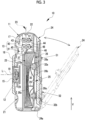
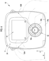
- a digital camera 10 including a printer comprises a camera body 11, an imaging unit 12, and a printer unit 13 (see Fig. 3 ).
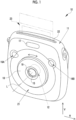
- An imaging window 15, two release switches 16A and 16B, a flash 17, and an operation ring 18 are provided on the front surface of the camera body 11.
- the shape of the camera body 11 viewed from the front surface is a square shape.
- the camera body 11 has a square shape where a vertical length L1 of the camera body 11 in a vertical direction V (first direction) and a horizontal length L2 of the camera body 11 in a horizontal direction (second direction) orthogonal to the vertical direction V are equal to each other, and the square shape also includes a case where the vertical length L1 and the horizontal length L2 are substantially equal to each other.
- the imaging window 15 is disposed at the center of the front surface of the camera body 11.
- the imaging window 15 allows an imaging optical system 19 (see Fig. 3 ) of the imaging unit 12 to be exposed to the outside.
- An optical axis L of the imaging optical system 19 is orthogonal to the vertical direction V and the horizontal direction H.
- the imaging optical system 19 is positioned at the center of the camera body 11 in the vertical direction V and the horizontal direction H.
- the imaging unit 12 includes the imaging optical system 19 and a solid-state imaging element 20 (see Fig. 3 ).
- the solid-state imaging element 20 is, for example, a complementary metal oxide semiconductor (CMOS) image sensor, and includes a light-receiving surface that is formed of a plurality of pixel (not shown) arranged in the form of a two-dimensional matrix.
- CMOS complementary metal oxide semiconductor
- Each of the pixels includes a photoelectric conversion element, and photoelectrically converts a subject image, which is formed on the light-receiving surface by the imaging optical system 19, to generate an imaging signal.
- the solid-state imaging element 20 comprises signal processing circuits, such as a noise removal circuit, an automatic gain controller, and an A/D conversion circuit, (all of them are not shown).
- the noise removal circuit performs noise removal processing on an imaging signal.
- the automatic gain controller amplifies the level of an imaging signal to an optimum value.
- the A/D conversion circuit converts an imaging signal into a digital signal and outputs the digital signal to an internal memory (not shown) from the solid-state imaging element 20.
- An output signal of the solid-state imaging element 20 is image data (so-called RAW data) that has one color signal for each pixel.
- a grip portion 21 is formed on the camera body 11 at positions that are symmetric with respect to the vertical axis AV and are symmetric with respect to the horizontal axis AH. Specifically, the grip portion 21 has an annular shape (the shape of a ring) and a concave shape that is concave from the surface around the grip portion 21.
- the imaging optical system 19 is positioned at the center of the annular grip portion 21 in a case where the digital camera 10 including a printer is viewed from the front surface of the camera body 11. Further, the grip portion 21 is formed so that the shape of the cross section of the grip portion 21 taken along the optical axis L has the shape of an arc (see Fig. 3 ).
- the positions, which are symmetric with respect to the axis, include positions that are substantially symmetric with respect to the axis.
- the release switches 16A and 16B are disposed at positions that are symmetric with respect to the vertical axis AV. Specifically, the release switches 16A and 16B are disposed at positions that are equidistant from the vertical axis AV. In a case where at least one of the release switch 16A or 16B is operated to be pressed, the solid-state imaging element 20 to be described later is driven and a subject image is taken.
- a part of the release switches 16A and 16B are disposed in the grip portion 21. Portions of the release switches 16A and 16B, which are disposed in the grip portion 21, are formed in the shape of a curved surface that is concave along the concave shape.
- the flash 17 is disposed at a position that corresponds to the imaging optical system 19 in the horizontal direction H, that is, on the vertical axis AV.
- Corresponding which is mentioned here, includes a case where the flash 17 is disposed at a position substantially corresponding to the imaging optical system. For example, in a case where an exposure value is equal to or smaller than a predetermined value when the imaging unit 12 images a subject, the flash 17 automatically irradiates the subject with illumination light.
- the operation ring 18 is a ring-shaped operation member that is positioned between the grip portion 21 and the imaging optical system 19, and is mounted so as to be movable rotationally about the optical axis L.
- the operation ring 18 is an operation member that is operated to turn on or off the power supply of the digital camera 10 including a printer.
- a film discharge port 22 is provided on one end of the camera body 11 in the vertical direction V, that is, the upper surface of the camera body 11. Although described in detail, a film unit 23 on which an image has been printed is discharged from the film discharge port 22.
- a loading lid 24 is provided on the back side of the camera body 11.
- the loading lid 24 is mounted through a hinge portion 24a that is provided at the lower end of the camera body 11.
- the loading lid 24 is supported so as to be movable rotationally between an open position (a position shown by a two-dot chain line) where a film pack loading chamber 25 provided in the camera body 11 is opened and a closed position (a position shown by a solid line) where the film pack loading chamber 25 is covered.
- a film pack 26 is loaded in the film pack loading chamber 25.
- the film pack 26 includes a box-shaped case 26a and a lid 26b that covers the opening of the case 26a.
- a plurality of film units 23 are superimposed and stored in the case 26a so that exposure surfaces 23a of the plurality of film units 23 face the left side in Fig. 3 .
- the film sending port 27 is closed from the outside by a light-shielding seal (not shown) having flexibility.
- a pair of openings 28a and 28b is formed in the lid 26b with a predetermined interval therebetween. Further, a support piece 29, film unit-pressing plates 30, and the like are provided on the inner surface of the lid 26b.
- the openings 28a and 28b are inlets where pressing members 32a and 32b provided on the inner surface of the loading lid 24 enter in a case where the loading lid 24 is closed.
- the support piece 29 supports the middle portion of the film unit 23 from behind.
- the film unit-pressing plates 30 are pressed by the pressing members 32a and 32b and are bent to be convex toward the bottom of the case 26a. Accordingly, the lowermost film unit 23 is pushed against the bottom of the case 26a.
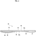
- the film unit 23 as a recording medium is a so-called mono-sheet film.
- the film unit 23 includes a mask sheet 33, a photosensitive sheet 34, a cover sheet 35, a developer pod 36, and a trap portion 37.
- the mask sheet 33 is formed of plastic in the shape of a thin sheet, and comprises a screen opening 33a.
- the photosensitive sheet 34 is provided with a photosensitive layer, a diffusive-reflective layer, an image-receiving layer, and the like.
- the cover sheet 35 includes an exposure surface 23a that faces an exposure head 41 to be described later.
- the developer pod 36 is formed substantially in the shape of a bag, and is filled with a developer 38.
- the developer pod 36 is bonded to an end portion of the photosensitive sheet 34 facing the film sending port 27, and is wrapped with an end portion of the mask sheet 33.
- the trap portion 37 is bonded to an end portion of the photosensitive sheet 34 opposite to the film sending port 27, and is wrapped with an end portion of the mask sheet 33 likewise.
- the photosensitive layer of the film unit 23 is irradiated with printing light and is exposed during printing. Then, the developer pod 36 is torn and opened at the time of development, and the developer 38 flows into a gap 39 between the photosensitive sheet 34 and the cover sheet 35 and is spread. Accordingly, a latent image is photochemically formed on the photosensitive layer, is reversed by the diffusive-reflective layer, and is transferred to the image-receiving layer. In this way, a positive image appears on a positive image observation surface 40 of the photosensitive sheet 34 that is exposed through the screen opening 33a.
- the lowermost film unit 23 is sent to the outside of the film pack 26 through the film sending port 27 by a claw (not shown) that is inserted into a claw opening (not shown) of the bottom of the case 26a.
- the film unit 23, which is sent to the outside of the film pack 26, (a position shown by a two-dot chain line) is subjected to exposure processing and development processing by the printer unit 13 that is provided between the film sending port 27 and the film discharge port 22.
- the printer unit 13 includes an exposure head 41 and a developer spreading unit 42 that are arranged in this order toward the film discharge port 22 from the film sending port 27.
- the exposure head 41 includes a light source, a liquid crystal shutter, a lens, and the like, and is disposed at a position facing a film unit-transport path.
- the exposure head 41 is positioned between the flash 17 and the imaging unit 12 in the vertical direction V. Accordingly, the camera body 11 can be reduced in thickness.
- the film unit-transport path along which the film unit 23 is transported by the developer spreading unit 42 is positioned between the imaging unit 12 and a back display unit 51 to be described later. Accordingly, the camera body 11 can be reduced in size.
- the exposure head 41 irradiates the exposure surface 23a of the film unit 23 with linear printing light that is parallel to a main scanning direction (a width direction of the film unit). Accordingly, a line image, which has a gradation according to image data, is exposed to the photosensitive layer of the film unit 23.
- the developer spreading unit 42 comprises transport rollers 43 and 44 and spreading rollers 45 and 46.
- the transport rollers 43 and 44 and the spreading rollers 45 and 46 are rotationally driven by a motor (not shown).
- the transport roller 44 is pressed toward the transport roller 43 by a spring 47 as a pressing mechanism
- the spreading roller 46 is pressed toward the spreading roller 45 by a spring 48 as a pressing mechanism.
- the transport rollers 43 and 44 pinch both side portions of the film unit 23, which is sent from the film pack 26, and transport the film unit 23 toward the spreading rollers 45 and 46.
- An exposure position P where the exposure head 41 exposes the film unit 23 to printing light is positioned between the film sending port 27 of the film pack 26 and the transport rollers 43 and 44. Accordingly, the camera body 11 can be reduced in thickness.
- the spreading rollers 45 and 46 pinch the film unit 23, which is delivered from the transport rollers 43 and 44, over the entire width of the film unit 23 and allow the developer pod 36 to be torn and opened and allow the developer 38 to be spread into the gap 39 while transporting the film unit 23 toward the film discharge port 22.
- the film unit 23, which has been subjected to development processing by the spreading rollers 45 and 46, is transported to the film discharge port 22 and is discharged to the outside of the camera body 11.
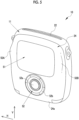
- a back display unit 51 and an operation unit 52 are provided on the outer surface of the loading lid 24, that is, the back of the camera body 11.
- the back display unit 51 is formed of, for example, a liquid crystal display (LCD) panel.
- Image data corresponding to one frame, which is output from the solid-state imaging element 20, is sequentially input to the back display unit 51, and is displayed on the back display unit 51 as a live view image.
- image data output from the solid-state imaging element 20 is subjected to compression processing after being subjected to publicly known image processing, such as matrix calculation, demosaicing processing, ⁇ correction, brightness conversion, color difference conversion, and resizing, by an image processing unit (not shown). Then, the image data, which has been subjected to the image processing and compression, is recorded in the internal memory (not shown), such as a flash memory, provided in the camera body 11.
- image processing unit not shown
- a pair of finger rest portions 53A and 53B which protrudes from the back of the camera body 11, is provided on the outer surface of the loading lid 24.
- the finger rest portions 53A and 53B continue from both side surfaces of the camera body 11 and are formed in the shape of a triangular protrusion that protrudes toward the rear side of the camera body 11.
- the operation unit 52 includes a plurality of switches, which are used to perform various operations of the digital camera 10 including a printer, in addition to the menu switch 52A and the printing switch 52B having been described above.
- the display unit 51 and the operation unit 52 are positioned between the finger rest portions 53A and 53B in the horizontal direction H. More specifically, the operation unit 52 is disposed at a position where a distance L3 between the center of the operation unit 52 and the apex of the finger rest portion 53A is equal to a distance L4 between the center of the operation unit 52 and the apex of the finger rest portion 53B.
- the action of the digital camera 10 including a printer will be described with reference to Figs. 7A, 7B , and 8 .
- the operation ring 18 is operated to move rotationally to turn on the power supply of the digital camera 10 including a printer
- power is supplied to each unit.
- an imaging mode is set at this point of time and the solid-state imaging element 20 of the imaging unit 12 is driven.
- the solid-state imaging element 20 continuously takes subject images and the images are displayed on the back display unit 51. The user frames a subject while viewing the back display unit 51.
- the user performs imaging by vertical imaging (see Fig. 7A ) that is performed in a state where the camera body 11 is oriented vertically or horizontal imaging (see Fig. 7B ) that is performed in a state where the camera body 11 is oriented horizontally, according to framing. Since the grip portion 21 is formed on the camera body 11 of the digital camera 10 including a printer, the user can reliably hold the camera body 11 with one's own right and left hands as shown in Figs. 7A and 7B even in any case of the vertical imaging and the horizontal imaging. For this reason, the camera body 11 is easily held and a holding feeling is improved.
- the camera body 11 has a square shape, the user can hold the camera body 11 in the same holding way and with the same force even in any case of the vertical imaging and the horizontal imaging. Accordingly, the ease of holding and a holding feeling are further improved.
- the grip portion 21 is formed in the shape of a ring, the user can reliably hold the camera body 11 even though the camera body 11 is oriented obliquely as in the case of an intermediate position between the vertical imaging and the horizontal imaging.
- image data output from the solid-state imaging element 20 is recorded in the internal memory at that time.
- an image is played back and displayed on the back display unit 51 on the basis of the image data recorded in the internal memory, and printing processing to be performed by the printer unit 13 is started in a case where an image to be wanted to be printed is displayed on the back display unit 51 and the user presses the printing switch 52B of the operation unit 52.
- the film unit 23 which is discharged to the outside of the film pack 26 through the film sending port 27, is pinched and transported by the transport rollers 43 and 44. Then, exposure to be performed by the exposure head 41 is performed during the transport of the film unit 23.
- the exposure head 41 exposes an image (latent image), which corresponds to one screen, to the photosensitive layer of the film unit 23 on the basis of the image data recorded in the internal memory. Subsequently, the film unit 23 is transported toward the spreading rollers 45 and 46, and is pinched and transported by the spreading rollers 45 and 46. Accordingly, the developer 38 is spread into the gap 39 (see Fig. 4 ) as described above.
- the film unit 23 which has been subjected to development processing, is transported to the film discharge port 22 and is discharged to the outside of the camera body 11. Then, after predetermined time has passed, a positive image appears on the positive image observation surface 40 of the discharged film unit 23.
- the release switches 16A and 16B are disposed in the grip portion 21 as described above, the user can recognize the positions of the release switches 16A and 16B through only the feeling of fingertips. As a result, operability is improved. Furthermore, since the release switches 16A and 16B are disposed at positions that are symmetric with respect to the vertical axis AV, it is easy for the user to press the release switches 16A and 16B even in any case of the vertical imaging and the horizontal imaging.
- the camera body 11 is provided with the pair of finger rest portions 53A and 53B that protrudes from the back, it is easy for the user to hold the camera body 11 while putting the thumbs on the finger rest portions 53A and 53B as shown in Fig. 8 . Furthermore, since the operation unit 52 is positioned between the finger rest portions 53A and 53B, it is possible to easily perform various operations of the digital camera 10 including a printer while holding the camera body 11.
- a part of the release switches 16A and 16B are disposed in the grip portion 21 in the first embodiment, but the entire release switches 16A and 16B are disposed in the grip portion 21 as shown in Fig. 9 in a second embodiment.
- the release switches 16A and 16B are formed in the shape of a curved surface that is concave along the concave shape. Accordingly, as with the first embodiment, operability is improved since a user can recognize the positions of the release switches 16A and 16B through only the feeling of fingertips.
- the grip portion 21 has an annular shape and a concave shape in each of the embodiments, but a grip portion 21 has the shape of a rectangular frame and a concave shape as shown in Fig. 10 in a third embodiment.
- An imaging optical system 19 is positioned at the center of the annular grip portion 21 in a case where a digital camera 10 including a printer is viewed from the front surface of the camera body 11. That is, as with the first embodiment, the grip portion 21 is formed at positions that are symmetric with respect to the vertical axis AV and are symmetric with respect to the horizontal axis AH. Further, the entire release switches 16A and 16B are disposed in the grip portion 21 as with the second embodiment, but a part of the release switches 16A and 16B may be disposed in the grip portion 21 as with the first embodiment.
- the grip portion 21 has the shape of one ring and a concave shape in each of the embodiments, but a grip portion 21 has a plurality of concave areas or convex areas as shown in Fig. 11 in a fourth embodiment.
- the grip portion 21 is formed with four concave areas 21A to 21D, and the concave areas 21A and 21B are formed at positions symmetric with respect to the horizontal axis AH and the concave areas 21C and 21D are formed at positions symmetric with respect to the vertical axis AV.
- a part of the release switches 16A and 16B are disposed in the grip portion 21 as with the first embodiment, but the entire release switches 16A and 16B may be disposed in the grip portion 21 as with the second embodiment.
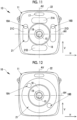
- the release switches 16A and 16B are disposed at positions symmetric with respect to the vertical axis AV in each of the embodiments, but may be disposed at positions rotationally symmetric with respect to the imaging optical system 19 as a center by an angle of 180°, specifically, at positions rotationally symmetric with respect to the optical axis L as a center by an angle of 180° as shown in Fig. 12 in a fifth embodiment.
- the entire release switches 16A and 16B are disposed in the grip portion 21 as with the second embodiment, but a part of the release switches 16A and 16B may be disposed in the grip portion 21 as with the first embodiment.
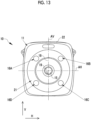
- the camera body 11 is provided with two release switches 16A and 16B in each of the embodiments, but the camera body 11 is provided with four release switches 16A to 16D as shown in Fig. 13 in a sixth embodiment.
- the release switches 16A to 16D are disposed at positions that are symmetric with respect to the vertical axis AV and are symmetric with respect to the horizontal axis AH.
- the entire release switches 16A to 16D are disposed in the grip portion 21 as with the second embodiment, but a part of the release switches 16A to 16D may be disposed in the grip portion 21 as with the first embodiment.
- the grip portion 21 has a concave shape that is concave from the surface around the grip portion 21 in each of the embodiments, but is not limited thereto and may have a convex shape that is convex from the surface around the grip portion 21.
- the release switches are formed in the shape of a curved surface convex along the convex shape of the grip portion 21.
- the first direction is set to the vertical direction V and the second direction is set to the horizontal direction H in each of the embodiments, but the first direction may be set to the horizontal direction H and the second direction may be set to the vertical direction V.
- thermosensitive recording paper in which thermosensitive coloring layers are laminated, plain paper, exclusive paper (paper of which the surfaces are coated, and the like), an OHP sheet can be used as the recording medium.
- thermosensitive recording paper thermal recording using a thermal head is performed.
- plain paper or the like is used as the recording medium, recording using ink jet, thermal fusion, thermal transfer, or the like is performed.
Landscapes
- Physics & Mathematics (AREA)
- General Physics & Mathematics (AREA)
- Engineering & Computer Science (AREA)
- Multimedia (AREA)
- Signal Processing (AREA)
- Microelectronics & Electronic Packaging (AREA)
- Studio Devices (AREA)
- Cameras Adapted For Combination With Other Photographic Or Optical Apparatuses (AREA)
- Camera Bodies And Camera Details Or Accessories (AREA)
- Stroboscope Apparatuses (AREA)
- Cameras In General (AREA)
Applications Claiming Priority (2)
| Application Number | Priority Date | Filing Date | Title |
|---|---|---|---|
| JP2016181503A JP6568029B2 (ja) | 2016-09-16 | 2016-09-16 | プリンタ付きデジタルカメラ |
| PCT/JP2017/033125 WO2018052040A1 (ja) | 2016-09-16 | 2017-09-13 | プリンタ付きデジタルカメラ |
Publications (3)
| Publication Number | Publication Date |
|---|---|
| EP3514619A1 EP3514619A1 (en) | 2019-07-24 |
| EP3514619A4 EP3514619A4 (en) | 2019-07-24 |
| EP3514619B1 true EP3514619B1 (en) | 2023-08-09 |
Family
ID=61619570
Family Applications (1)
| Application Number | Title | Priority Date | Filing Date |
|---|---|---|---|
| EP17850941.0A Active EP3514619B1 (en) | 2016-09-16 | 2017-09-13 | Printer-equipped digital camera |
Country Status (5)
| Country | Link |
|---|---|
| US (1) | US10642129B2 (https=) |
| EP (1) | EP3514619B1 (https=) |
| JP (1) | JP6568029B2 (https=) |
| CN (1) | CN109716231B (https=) |
| WO (1) | WO2018052040A1 (https=) |
Families Citing this family (8)
| Publication number | Priority date | Publication date | Assignee | Title |
|---|---|---|---|---|
| DE102018100728A1 (de) * | 2018-01-15 | 2019-07-18 | Xarpotech Ug (Haftungsbeschränkt) | Organische Photorezeptoren |
| JP1706220S (https=) * | 2021-03-17 | 2022-01-28 | ||
| JP1711074S (https=) * | 2021-06-21 | 2022-03-29 | ||
| JP1719324S (ja) * | 2021-09-16 | 2022-07-08 | インスタントカメラ | |
| JP1719325S (ja) * | 2021-09-16 | 2022-07-08 | インスタントカメラ | |
| JP1719323S (ja) * | 2021-09-16 | 2022-07-08 | インスタントカメラ | |
| JP1782234S (ja) * | 2024-03-28 | 2024-10-15 | デジタルカメラ | |
| USD1077890S1 (en) * | 2025-01-06 | 2025-06-03 | Shenzhen SiXing Digital Technology Co., Ltd. | Children's camera |
Family Cites Families (30)
| Publication number | Priority date | Publication date | Assignee | Title |
|---|---|---|---|---|
| US3530778A (en) * | 1968-04-01 | 1970-09-29 | Polaroid Corp | Photographic camera |
| US4181414A (en) * | 1976-03-12 | 1980-01-01 | Canon Kabushiki Kaisha | Self developing camera with film feedout control |
| JPS63150939U (https=) * | 1987-03-25 | 1988-10-04 | ||
| US5218390A (en) * | 1991-04-15 | 1993-06-08 | Eastman Kodak Company | Compact camera with integral body grip |
| JPH1010626A (ja) * | 1996-06-24 | 1998-01-16 | Canon Inc | カメラ |
| JPH114372A (ja) * | 1997-06-11 | 1999-01-06 | Sanyo Electric Co Ltd | 画像印刷装置及びカメラ |
| JPH11249233A (ja) * | 1998-02-27 | 1999-09-17 | Fuji Photo Film Co Ltd | プリンタ付き電子カメラ |
| JPH11317897A (ja) * | 1998-05-07 | 1999-11-16 | Casio Comput Co Ltd | プリンタ付きカメラ装置 |
| AUPQ056099A0 (en) * | 1999-05-25 | 1999-06-17 | Silverbrook Research Pty Ltd | A method and apparatus (pprint01) |
| JP3999449B2 (ja) * | 2000-07-27 | 2007-10-31 | 富士フイルム株式会社 | フイルム押さえ装置 |
| JP2002040534A (ja) | 2000-07-27 | 2002-02-06 | Nikon Corp | カメラ |
| US6301438B1 (en) * | 2000-09-13 | 2001-10-09 | Polaroid Corporation | Film advancement assembly for a self-developing camera |
| JP2002296659A (ja) * | 2000-10-02 | 2002-10-09 | Fuji Photo Film Co Ltd | カメラ |
| US6504999B2 (en) * | 2000-10-02 | 2003-01-07 | Fuji Photo Film Co., Ltd. | Camera with printer |
| JP2002137451A (ja) * | 2000-11-07 | 2002-05-14 | Fuji Photo Film Co Ltd | 光ヘッド装置 |
| JP2002330373A (ja) * | 2001-05-07 | 2002-11-15 | Canon Inc | カートリッジロック装置、撮像装置及びカートリッジロック方法 |
| JP4515665B2 (ja) * | 2001-07-24 | 2010-08-04 | ローム株式会社 | プリント機能付きカメラ |
| JP2003134372A (ja) * | 2001-10-23 | 2003-05-09 | Fuji Photo Film Co Ltd | カメラ |
| JP4249942B2 (ja) * | 2002-05-09 | 2009-04-08 | 富士フイルム株式会社 | カメラ |
| JP2004212831A (ja) * | 2003-01-08 | 2004-07-29 | Fuji Photo Film Co Ltd | インスタントカメラおよび記録装置 |
| JP2004340991A (ja) * | 2003-05-13 | 2004-12-02 | Fuji Photo Film Co Ltd | カメラ |
| JP4339218B2 (ja) * | 2004-09-24 | 2009-10-07 | 富士フイルム株式会社 | 画像記録装置 |
| CN2786655Y (zh) * | 2005-02-22 | 2006-06-07 | 赵永生 | “612”宽幅120照相机 |
| JP2007329657A (ja) * | 2006-06-07 | 2007-12-20 | Canon Inc | 撮像装置 |
| JP6071544B2 (ja) * | 2012-12-27 | 2017-02-01 | キヤノン株式会社 | 撮像装置 |
| JP6427906B2 (ja) * | 2013-08-19 | 2018-11-28 | ソニー株式会社 | 撮像装置 |
| JP5541430B1 (ja) | 2013-08-19 | 2014-07-09 | ソニー株式会社 | 撮像ユニット、装着装置 |
| JP6296894B2 (ja) * | 2014-05-14 | 2018-03-20 | キヤノン株式会社 | 電子機器 |
| EP3306387B1 (en) * | 2015-11-16 | 2018-10-03 | Axis AB | An elastic gasket, the use thereof, and a system comprising the elastic gasket |
| WO2018147069A1 (ja) * | 2017-02-10 | 2018-08-16 | 富士フイルム株式会社 | インスタントフィルムパック及びそれを用いる装置類 |
-
2016
- 2016-09-16 JP JP2016181503A patent/JP6568029B2/ja active Active
-
2017
- 2017-09-13 EP EP17850941.0A patent/EP3514619B1/en active Active
- 2017-09-13 CN CN201780056613.9A patent/CN109716231B/zh active Active
- 2017-09-13 WO PCT/JP2017/033125 patent/WO2018052040A1/ja not_active Ceased
-
2019
- 2019-03-15 US US16/354,531 patent/US10642129B2/en active Active
Also Published As
| Publication number | Publication date |
|---|---|
| WO2018052040A1 (ja) | 2018-03-22 |
| US10642129B2 (en) | 2020-05-05 |
| JP6568029B2 (ja) | 2019-08-28 |
| CN109716231A (zh) | 2019-05-03 |
| US20190212635A1 (en) | 2019-07-11 |
| JP2018045178A (ja) | 2018-03-22 |
| CN109716231B (zh) | 2021-08-17 |
| EP3514619A1 (en) | 2019-07-24 |
| EP3514619A4 (en) | 2019-07-24 |
Similar Documents
| Publication | Publication Date | Title |
|---|---|---|
| EP3514619B1 (en) | Printer-equipped digital camera | |
| JP3862132B2 (ja) | 電子スチルカメラ | |
| EP3361310B1 (en) | Developer spreading device, printer and digital camera with printer | |
| CN108234803B (zh) | 打印机及带有打印机的数码相机以及打印机的信息显示方法 | |
| US11520215B2 (en) | Printer and digital camera with printer | |
| EP3361309B1 (en) | Developer spreading device, printer and digital camera with printer | |
| US12291419B2 (en) | Transport device for instant film, printer, and digital camera including printer | |
| EP3361311B1 (en) | Instant film pack and device using the same | |
| EP3582001B1 (en) | Instant film pack and devices using same | |
| US11736631B2 (en) | Printer-equipped digital camera and displaying control method thereof | |
| US11463593B2 (en) | Printer-equipped camera | |
| US11995804B2 (en) | Printer-equipped camera and displaying control method thereof | |
| US12393105B2 (en) | Printer and digital camera with printer | |
| JP2002182311A (ja) | 光プリンタ | |
| JP2001330898A (ja) | インスタントプリンタ及びプリント方法及び露光装置並びに露光方法 | |
| JPH1146344A (ja) | 画像記録装置および撮影装置 |
Legal Events
| Date | Code | Title | Description |
|---|---|---|---|
| STAA | Information on the status of an ep patent application or granted ep patent |
Free format text: STATUS: THE INTERNATIONAL PUBLICATION HAS BEEN MADE |
|
| PUAI | Public reference made under article 153(3) epc to a published international application that has entered the european phase |
Free format text: ORIGINAL CODE: 0009012 |
|
| STAA | Information on the status of an ep patent application or granted ep patent |
Free format text: STATUS: REQUEST FOR EXAMINATION WAS MADE |
|
| 17P | Request for examination filed |
Effective date: 20190315 |
|
| A4 | Supplementary search report drawn up and despatched |
Effective date: 20190617 |
|
| AK | Designated contracting states |
Kind code of ref document: A1 Designated state(s): AL AT BE BG CH CY CZ DE DK EE ES FI FR GB GR HR HU IE IS IT LI LT LU LV MC MK MT NL NO PL PT RO RS SE SI SK SM TR |
|
| AX | Request for extension of the european patent |
Extension state: BA ME |
|
| DAV | Request for validation of the european patent (deleted) | ||
| DAX | Request for extension of the european patent (deleted) | ||
| STAA | Information on the status of an ep patent application or granted ep patent |
Free format text: STATUS: EXAMINATION IS IN PROGRESS |
|
| 17Q | First examination report despatched |
Effective date: 20200616 |
|
| RAP3 | Party data changed (applicant data changed or rights of an application transferred) |
Owner name: FUJIFILM CORPORATION |
|
| REG | Reference to a national code |
Ref country code: DE Ref legal event code: R079 Free format text: PREVIOUS MAIN CLASS: G03B0017500000 Ipc: G03B0017530000 Ref document number: 602017072595 Country of ref document: DE |
|
| GRAP | Despatch of communication of intention to grant a patent |
Free format text: ORIGINAL CODE: EPIDOSNIGR1 |
|
| STAA | Information on the status of an ep patent application or granted ep patent |
Free format text: STATUS: GRANT OF PATENT IS INTENDED |
|
| RIC1 | Information provided on ipc code assigned before grant |
Ipc: H04N 23/57 20230101ALN20230124BHEP Ipc: G03D 5/00 20060101ALN20230124BHEP Ipc: G03B 15/05 20060101ALN20230124BHEP Ipc: H04N 23/51 20230101ALI20230124BHEP Ipc: G03B 17/02 20060101ALI20230124BHEP Ipc: G03B 17/52 20060101ALI20230124BHEP Ipc: G03B 17/53 20060101AFI20230124BHEP |
|
| RIC1 | Information provided on ipc code assigned before grant |
Ipc: H04N 23/57 20230101ALN20230210BHEP Ipc: G03D 5/00 20060101ALN20230210BHEP Ipc: G03B 15/05 20060101ALN20230210BHEP Ipc: H04N 23/51 20230101ALI20230210BHEP Ipc: G03B 17/02 20060101ALI20230210BHEP Ipc: G03B 17/52 20060101ALI20230210BHEP Ipc: G03B 17/53 20060101AFI20230210BHEP |
|
| INTG | Intention to grant announced |
Effective date: 20230227 |
|
| P01 | Opt-out of the competence of the unified patent court (upc) registered |
Effective date: 20230515 |
|
| GRAS | Grant fee paid |
Free format text: ORIGINAL CODE: EPIDOSNIGR3 |
|
| GRAA | (expected) grant |
Free format text: ORIGINAL CODE: 0009210 |
|
| STAA | Information on the status of an ep patent application or granted ep patent |
Free format text: STATUS: THE PATENT HAS BEEN GRANTED |
|
| AK | Designated contracting states |
Kind code of ref document: B1 Designated state(s): AL AT BE BG CH CY CZ DE DK EE ES FI FR GB GR HR HU IE IS IT LI LT LU LV MC MK MT NL NO PL PT RO RS SE SI SK SM TR |
|
| REG | Reference to a national code |
Ref country code: GB Ref legal event code: FG4D |
|
| REG | Reference to a national code |
Ref country code: CH Ref legal event code: EP |
|
| REG | Reference to a national code |
Ref country code: IE Ref legal event code: FG4D |
|
| REG | Reference to a national code |
Ref country code: DE Ref legal event code: R096 Ref document number: 602017072595 Country of ref document: DE |
|
| REG | Reference to a national code |
Ref country code: LT Ref legal event code: MG9D |
|
| REG | Reference to a national code |
Ref country code: NL Ref legal event code: MP Effective date: 20230809 |
|
| REG | Reference to a national code |
Ref country code: AT Ref legal event code: MK05 Ref document number: 1598209 Country of ref document: AT Kind code of ref document: T Effective date: 20230809 |
|
| PG25 | Lapsed in a contracting state [announced via postgrant information from national office to epo] |
Ref country code: GR Free format text: LAPSE BECAUSE OF FAILURE TO SUBMIT A TRANSLATION OF THE DESCRIPTION OR TO PAY THE FEE WITHIN THE PRESCRIBED TIME-LIMIT Effective date: 20231110 |
|
| PG25 | Lapsed in a contracting state [announced via postgrant information from national office to epo] |
Ref country code: IS Free format text: LAPSE BECAUSE OF FAILURE TO SUBMIT A TRANSLATION OF THE DESCRIPTION OR TO PAY THE FEE WITHIN THE PRESCRIBED TIME-LIMIT Effective date: 20231209 |
|
| PG25 | Lapsed in a contracting state [announced via postgrant information from national office to epo] |
Ref country code: SE Free format text: LAPSE BECAUSE OF FAILURE TO SUBMIT A TRANSLATION OF THE DESCRIPTION OR TO PAY THE FEE WITHIN THE PRESCRIBED TIME-LIMIT Effective date: 20230809 Ref country code: RS Free format text: LAPSE BECAUSE OF FAILURE TO SUBMIT A TRANSLATION OF THE DESCRIPTION OR TO PAY THE FEE WITHIN THE PRESCRIBED TIME-LIMIT Effective date: 20230809 Ref country code: PT Free format text: LAPSE BECAUSE OF FAILURE TO SUBMIT A TRANSLATION OF THE DESCRIPTION OR TO PAY THE FEE WITHIN THE PRESCRIBED TIME-LIMIT Effective date: 20231211 Ref country code: NO Free format text: LAPSE BECAUSE OF FAILURE TO SUBMIT A TRANSLATION OF THE DESCRIPTION OR TO PAY THE FEE WITHIN THE PRESCRIBED TIME-LIMIT Effective date: 20231109 Ref country code: NL Free format text: LAPSE BECAUSE OF FAILURE TO SUBMIT A TRANSLATION OF THE DESCRIPTION OR TO PAY THE FEE WITHIN THE PRESCRIBED TIME-LIMIT Effective date: 20230809 Ref country code: LV Free format text: LAPSE BECAUSE OF FAILURE TO SUBMIT A TRANSLATION OF THE DESCRIPTION OR TO PAY THE FEE WITHIN THE PRESCRIBED TIME-LIMIT Effective date: 20230809 Ref country code: LT Free format text: LAPSE BECAUSE OF FAILURE TO SUBMIT A TRANSLATION OF THE DESCRIPTION OR TO PAY THE FEE WITHIN THE PRESCRIBED TIME-LIMIT Effective date: 20230809 Ref country code: IS Free format text: LAPSE BECAUSE OF FAILURE TO SUBMIT A TRANSLATION OF THE DESCRIPTION OR TO PAY THE FEE WITHIN THE PRESCRIBED TIME-LIMIT Effective date: 20231209 Ref country code: HR Free format text: LAPSE BECAUSE OF FAILURE TO SUBMIT A TRANSLATION OF THE DESCRIPTION OR TO PAY THE FEE WITHIN THE PRESCRIBED TIME-LIMIT Effective date: 20230809 Ref country code: GR Free format text: LAPSE BECAUSE OF FAILURE TO SUBMIT A TRANSLATION OF THE DESCRIPTION OR TO PAY THE FEE WITHIN THE PRESCRIBED TIME-LIMIT Effective date: 20231110 Ref country code: FI Free format text: LAPSE BECAUSE OF FAILURE TO SUBMIT A TRANSLATION OF THE DESCRIPTION OR TO PAY THE FEE WITHIN THE PRESCRIBED TIME-LIMIT Effective date: 20230809 Ref country code: AT Free format text: LAPSE BECAUSE OF FAILURE TO SUBMIT A TRANSLATION OF THE DESCRIPTION OR TO PAY THE FEE WITHIN THE PRESCRIBED TIME-LIMIT Effective date: 20230809 |
|
| PG25 | Lapsed in a contracting state [announced via postgrant information from national office to epo] |
Ref country code: PL Free format text: LAPSE BECAUSE OF FAILURE TO SUBMIT A TRANSLATION OF THE DESCRIPTION OR TO PAY THE FEE WITHIN THE PRESCRIBED TIME-LIMIT Effective date: 20230809 |
|
| PG25 | Lapsed in a contracting state [announced via postgrant information from national office to epo] |
Ref country code: ES Free format text: LAPSE BECAUSE OF FAILURE TO SUBMIT A TRANSLATION OF THE DESCRIPTION OR TO PAY THE FEE WITHIN THE PRESCRIBED TIME-LIMIT Effective date: 20230809 |
|
| PG25 | Lapsed in a contracting state [announced via postgrant information from national office to epo] |
Ref country code: SM Free format text: LAPSE BECAUSE OF FAILURE TO SUBMIT A TRANSLATION OF THE DESCRIPTION OR TO PAY THE FEE WITHIN THE PRESCRIBED TIME-LIMIT Effective date: 20230809 Ref country code: RO Free format text: LAPSE BECAUSE OF FAILURE TO SUBMIT A TRANSLATION OF THE DESCRIPTION OR TO PAY THE FEE WITHIN THE PRESCRIBED TIME-LIMIT Effective date: 20230809 Ref country code: ES Free format text: LAPSE BECAUSE OF FAILURE TO SUBMIT A TRANSLATION OF THE DESCRIPTION OR TO PAY THE FEE WITHIN THE PRESCRIBED TIME-LIMIT Effective date: 20230809 Ref country code: EE Free format text: LAPSE BECAUSE OF FAILURE TO SUBMIT A TRANSLATION OF THE DESCRIPTION OR TO PAY THE FEE WITHIN THE PRESCRIBED TIME-LIMIT Effective date: 20230809 Ref country code: DK Free format text: LAPSE BECAUSE OF FAILURE TO SUBMIT A TRANSLATION OF THE DESCRIPTION OR TO PAY THE FEE WITHIN THE PRESCRIBED TIME-LIMIT Effective date: 20230809 Ref country code: CZ Free format text: LAPSE BECAUSE OF FAILURE TO SUBMIT A TRANSLATION OF THE DESCRIPTION OR TO PAY THE FEE WITHIN THE PRESCRIBED TIME-LIMIT Effective date: 20230809 Ref country code: SK Free format text: LAPSE BECAUSE OF FAILURE TO SUBMIT A TRANSLATION OF THE DESCRIPTION OR TO PAY THE FEE WITHIN THE PRESCRIBED TIME-LIMIT Effective date: 20230809 |
|
| REG | Reference to a national code |
Ref country code: CH Ref legal event code: PL |
|
| REG | Reference to a national code |
Ref country code: DE Ref legal event code: R097 Ref document number: 602017072595 Country of ref document: DE |
|
| PG25 | Lapsed in a contracting state [announced via postgrant information from national office to epo] |
Ref country code: LU Free format text: LAPSE BECAUSE OF NON-PAYMENT OF DUE FEES Effective date: 20230913 |
|
| REG | Reference to a national code |
Ref country code: BE Ref legal event code: MM Effective date: 20230930 |
|
| PG25 | Lapsed in a contracting state [announced via postgrant information from national office to epo] |
Ref country code: LU Free format text: LAPSE BECAUSE OF NON-PAYMENT OF DUE FEES Effective date: 20230913 Ref country code: IT Free format text: LAPSE BECAUSE OF FAILURE TO SUBMIT A TRANSLATION OF THE DESCRIPTION OR TO PAY THE FEE WITHIN THE PRESCRIBED TIME-LIMIT Effective date: 20230809 Ref country code: MC Free format text: LAPSE BECAUSE OF FAILURE TO SUBMIT A TRANSLATION OF THE DESCRIPTION OR TO PAY THE FEE WITHIN THE PRESCRIBED TIME-LIMIT Effective date: 20230809 |
|
| PLBE | No opposition filed within time limit |
Free format text: ORIGINAL CODE: 0009261 |
|
| STAA | Information on the status of an ep patent application or granted ep patent |
Free format text: STATUS: NO OPPOSITION FILED WITHIN TIME LIMIT |
|
| REG | Reference to a national code |
Ref country code: IE Ref legal event code: MM4A |
|
| PG25 | Lapsed in a contracting state [announced via postgrant information from national office to epo] |
Ref country code: IE Free format text: LAPSE BECAUSE OF NON-PAYMENT OF DUE FEES Effective date: 20230913 |
|
| 26N | No opposition filed |
Effective date: 20240513 |
|
| PG25 | Lapsed in a contracting state [announced via postgrant information from national office to epo] |
Ref country code: CH Free format text: LAPSE BECAUSE OF NON-PAYMENT OF DUE FEES Effective date: 20230930 |
|
| GBPC | Gb: european patent ceased through non-payment of renewal fee |
Effective date: 20231109 |
|
| PG25 | Lapsed in a contracting state [announced via postgrant information from national office to epo] |
Ref country code: IE Free format text: LAPSE BECAUSE OF NON-PAYMENT OF DUE FEES Effective date: 20230913 Ref country code: FR Free format text: LAPSE BECAUSE OF NON-PAYMENT OF DUE FEES Effective date: 20231009 Ref country code: CH Free format text: LAPSE BECAUSE OF NON-PAYMENT OF DUE FEES Effective date: 20230930 Ref country code: SI Free format text: LAPSE BECAUSE OF FAILURE TO SUBMIT A TRANSLATION OF THE DESCRIPTION OR TO PAY THE FEE WITHIN THE PRESCRIBED TIME-LIMIT Effective date: 20230809 |
|
| PG25 | Lapsed in a contracting state [announced via postgrant information from national office to epo] |
Ref country code: BE Free format text: LAPSE BECAUSE OF NON-PAYMENT OF DUE FEES Effective date: 20230930 |
|
| PGFP | Annual fee paid to national office [announced via postgrant information from national office to epo] |
Ref country code: DE Payment date: 20240730 Year of fee payment: 8 |
|
| PG25 | Lapsed in a contracting state [announced via postgrant information from national office to epo] |
Ref country code: GB Free format text: LAPSE BECAUSE OF NON-PAYMENT OF DUE FEES Effective date: 20231109 |
|
| PG25 | Lapsed in a contracting state [announced via postgrant information from national office to epo] |
Ref country code: GB Free format text: LAPSE BECAUSE OF NON-PAYMENT OF DUE FEES Effective date: 20231109 |
|
| PG25 | Lapsed in a contracting state [announced via postgrant information from national office to epo] |
Ref country code: BG Free format text: LAPSE BECAUSE OF FAILURE TO SUBMIT A TRANSLATION OF THE DESCRIPTION OR TO PAY THE FEE WITHIN THE PRESCRIBED TIME-LIMIT Effective date: 20230809 |
|
| PG25 | Lapsed in a contracting state [announced via postgrant information from national office to epo] |
Ref country code: BG Free format text: LAPSE BECAUSE OF FAILURE TO SUBMIT A TRANSLATION OF THE DESCRIPTION OR TO PAY THE FEE WITHIN THE PRESCRIBED TIME-LIMIT Effective date: 20230809 |
|
| PG25 | Lapsed in a contracting state [announced via postgrant information from national office to epo] |
Ref country code: CY Free format text: LAPSE BECAUSE OF FAILURE TO SUBMIT A TRANSLATION OF THE DESCRIPTION OR TO PAY THE FEE WITHIN THE PRESCRIBED TIME-LIMIT; INVALID AB INITIO Effective date: 20170913 |
|
| PG25 | Lapsed in a contracting state [announced via postgrant information from national office to epo] |
Ref country code: HU Free format text: LAPSE BECAUSE OF FAILURE TO SUBMIT A TRANSLATION OF THE DESCRIPTION OR TO PAY THE FEE WITHIN THE PRESCRIBED TIME-LIMIT; INVALID AB INITIO Effective date: 20170913 |
|
| PG25 | Lapsed in a contracting state [announced via postgrant information from national office to epo] |
Ref country code: TR Free format text: LAPSE BECAUSE OF FAILURE TO SUBMIT A TRANSLATION OF THE DESCRIPTION OR TO PAY THE FEE WITHIN THE PRESCRIBED TIME-LIMIT Effective date: 20230809 |