EP3514263B1 - Dispositif et procédé de traitement électrolytique d'une bande métallique - Google Patents
Dispositif et procédé de traitement électrolytique d'une bande métallique Download PDFInfo
- Publication number
- EP3514263B1 EP3514263B1 EP19152914.8A EP19152914A EP3514263B1 EP 3514263 B1 EP3514263 B1 EP 3514263B1 EP 19152914 A EP19152914 A EP 19152914A EP 3514263 B1 EP3514263 B1 EP 3514263B1
- Authority
- EP
- European Patent Office
- Prior art keywords
- surge
- metal strip
- electrode
- nozzle
- nozzles
- Prior art date
- Legal status (The legal status is an assumption and is not a legal conclusion. Google has not performed a legal analysis and makes no representation as to the accuracy of the status listed.)
- Active
Links
- 239000002184 metal Substances 0.000 title claims description 72
- 238000000034 method Methods 0.000 title claims description 18
- 238000000576 coating method Methods 0.000 title description 3
- 239000011248 coating agent Substances 0.000 title 1
- 238000011282 treatment Methods 0.000 claims description 73
- 238000004140 cleaning Methods 0.000 claims description 38
- 239000007788 liquid Substances 0.000 claims description 35
- 239000012670 alkaline solution Substances 0.000 claims description 3
- 239000003792 electrolyte Substances 0.000 description 21
- 230000000694 effects Effects 0.000 description 11
- 238000012423 maintenance Methods 0.000 description 9
- 238000005265 energy consumption Methods 0.000 description 7
- 230000002829 reductive effect Effects 0.000 description 6
- 239000003921 oil Substances 0.000 description 4
- 239000000243 solution Substances 0.000 description 4
- 238000005260 corrosion Methods 0.000 description 3
- 238000009434 installation Methods 0.000 description 3
- 239000012811 non-conductive material Substances 0.000 description 3
- 238000005452 bending Methods 0.000 description 2
- 238000011109 contamination Methods 0.000 description 2
- 238000007598 dipping method Methods 0.000 description 2
- 238000005868 electrolysis reaction Methods 0.000 description 2
- 239000004519 grease Substances 0.000 description 2
- 239000010687 lubricating oil Substances 0.000 description 2
- 239000000463 material Substances 0.000 description 2
- 239000002923 metal particle Substances 0.000 description 2
- 230000008439 repair process Effects 0.000 description 2
- 239000000725 suspension Substances 0.000 description 2
- 230000007704 transition Effects 0.000 description 2
- 239000007864 aqueous solution Substances 0.000 description 1
- 230000001174 ascending effect Effects 0.000 description 1
- 230000008859 change Effects 0.000 description 1
- 238000006243 chemical reaction Methods 0.000 description 1
- 230000007797 corrosion Effects 0.000 description 1
- 230000001419 dependent effect Effects 0.000 description 1
- 238000011161 development Methods 0.000 description 1
- 230000018109 developmental process Effects 0.000 description 1
- 238000007599 discharging Methods 0.000 description 1
- 238000009713 electroplating Methods 0.000 description 1
- 230000003628 erosive effect Effects 0.000 description 1
- 238000005530 etching Methods 0.000 description 1
- 239000012530 fluid Substances 0.000 description 1
- 230000005484 gravity Effects 0.000 description 1
- 238000007654 immersion Methods 0.000 description 1
- 239000011244 liquid electrolyte Substances 0.000 description 1
- 238000001465 metallisation Methods 0.000 description 1
- 238000005457 optimization Methods 0.000 description 1
- 230000036961 partial effect Effects 0.000 description 1
- 238000007747 plating Methods 0.000 description 1
- 230000008569 process Effects 0.000 description 1
- 230000009467 reduction Effects 0.000 description 1
- 230000000717 retained effect Effects 0.000 description 1
- 238000009420 retrofitting Methods 0.000 description 1
- 239000007921 spray Substances 0.000 description 1
- 230000003068 static effect Effects 0.000 description 1
- XLYOFNOQVPJJNP-UHFFFAOYSA-N water Substances O XLYOFNOQVPJJNP-UHFFFAOYSA-N 0.000 description 1
- 238000009736 wetting Methods 0.000 description 1
Images

Classifications
-
- C—CHEMISTRY; METALLURGY
- C25—ELECTROLYTIC OR ELECTROPHORETIC PROCESSES; APPARATUS THEREFOR
- C25F—PROCESSES FOR THE ELECTROLYTIC REMOVAL OF MATERIALS FROM OBJECTS; APPARATUS THEREFOR
- C25F1/00—Electrolytic cleaning, degreasing, pickling or descaling
-
- C—CHEMISTRY; METALLURGY
- C25—ELECTROLYTIC OR ELECTROPHORETIC PROCESSES; APPARATUS THEREFOR
- C25F—PROCESSES FOR THE ELECTROLYTIC REMOVAL OF MATERIALS FROM OBJECTS; APPARATUS THEREFOR
- C25F7/00—Constructional parts, or assemblies thereof, of cells for electrolytic removal of material from objects; Servicing or operating
Definitions
- the invention relates to a device and a method for the electrolytic treatment, in particular cleaning, of a metal strip which is transported along a transport direction through a treatment section of the device and is exposed to an electrolytic treatment liquid via a nozzle.
- the DE 31 08 615 A1 describes an apparatus for the electrolytic treatment of a metal strip, in particular for the electrolytic plating or descaling of the surfaces of the metal strip.
- the device has an electrolysis tank, in which there is an electrolytic liquid, and a number of rollers, which are arranged along a transport path of the metal strip.
- the metal strip is deflected in a zigzag fashion by the rollers and moves through the electrolysis tank.
- the apparatus further comprises paired electrode pads which are provided in parallel and face each other so that the metal strip for electrolytic treatment is transported vertically therebetween.
- Each electrode pad is provided with slits through which the electrolyte is discharged to the surface of the metal strip with a high static pressure.
- a voltage is applied between the metal strip, for example by contacting an electrically conductive roller, and the electrode pads.
- the electrode pads of the device set forth above are located outside the electrolytic bath.
- dip pole plates may be partially or substantially fully immersed in the electrolytic bath as described in FIG 1 the DE 31 08 615 A1 is shown.
- the metal strip is electroplated or electrolytically descaled by applying a voltage between the metal strip as the cathode and a dipped pole plate as the anode.
- Devices with an electrolytic bath and electrodes immersed in it are also known from JP H05 195300 A , JP H11 286185 A and JP 2004 268517A known.
- Another device for electrolytic treatment, such as cleaning, a metal strip is from DE 102 12 436 A1 out.
- the treatment of the metal strip takes place during vertical transport through a treatment area.
- the EP 0 870 854 B1 describes a device for the electrolytic cleaning of a metal strip.
- the metal strip to be cleaned is passed horizontally between opposite, facing nozzles.
- the nozzles spray an alkaline aqueous solution on both sides of the strip, with one of the nozzles being a positive electrode and the other nozzle being a negative electrode.
- the metal strip is brushed in a jet of clean water with brush rollers placed at positions in the direction of transport of the strip next to the nozzles.
- the energy requirement for the electrolytic treatment of a metal strip is high.
- An object of the invention is to provide an improved device and an improved method for the electrolytic treatment, preferably cleaning, of a metal strip.
- the device according to the invention is used for the electrolytic treatment of a metal strip using an electrolytic treatment liquid.
- the metal strip is transported along a transport direction through a treatment section.
- the metal strip can be transported, for example, by means of rollers.
- the device and the method set forth below are used for the electrolytic cleaning of the metal strip by means of an electrolytic cleaning liquid.
- “Cleaning” is understood here as meaning in particular the removal of surface coatings such as metal particles (Fe/Al fines), oil and grease contamination, anti-corrosion oils, lubricating oils and/or deep-drawing aids that reduce the coefficient of friction.
- the device has at least one surge nozzle, which has a surge opening and an electrode, with at least two surge nozzles being present according to the invention.
- the gush nozzle is configured to bring an electrolytic treatment liquid, which is preferably an alkaline solution, into contact with the electrode, discharge it from the gush opening, and apply it to at least one surface of the metal strip in the treatment section.
- the treatment liquid is preferably applied to the metal strip at a low pressure, for example less than 100 mbar.
- the device also has a Power supply that is set up to apply an AC voltage between the metal strip and the electrode.
- High current densities can be achieved on the metal strip to be treated by the alternating voltage applied in conjunction with a surge nozzle. This leads to increased activity of the treatment liquid due to stronger turbulence and better mixing. At the same time, the treatment liquid acts on a thin boundary layer in the transition between the treatment liquid and the strip surface, as a result of which the electrical current losses can be reduced. In this way, the specific energy consumption can be reduced.
- the technical effects are supported by the surge-like dispensing of the treatment liquid, i.e. the dispensing of the treatment liquid at a pressure that is preferably low in comparison to high-pressure nozzles. In addition, due to the reduced stray current, the corrosion tendency on metallic parts of the device is reduced.
- conventional dip pole plates or high-pressure nozzles can be dispensed with, which means that the maintenance and, if necessary, the replacement of such components is no longer necessary. This not only achieves a further reduction in energy consumption and maintenance costs, but also optimizes the availability of the device.
- the assembly and disassembly of conventional immersion pole plates is complicated.
- the surge nozzle can be easily decoupled from the cleaning tank, particularly when using flange plates. In this way, the surge nozzle can be removed from the side of the cleaning tank and installed in it for maintenance and repair work without dismantling other tank installations. Due to electrolytic erosion and alkaline attack by the treatment liquid, the electrodes of the surge nozzles (similar to the dip pole plates) are wear components that require replacement and maintenance at regular intervals for safety and process reasons.
- the device has at least two, particularly preferably exactly two, surge nozzles, which are arranged in pairs, so that the treatment section is located between two surge nozzles arranged in pairs.
- each surge nozzle has a surge opening and an electrode further arranged to bring the electrolytic treatment liquid into contact with the electrode, discharge it from the associated surge port, and apply it to at least one surface of the metal strip in the treatment section.
- the surge openings of two surge nozzles arranged in pairs face one another here, so that the metal strip passing through the treatment section can be subjected to treatment liquid on both sides.
- the power supply is set up to apply an AC voltage between the metal strip and the electrodes of each of the surge nozzles.
- the above preferred embodiment enables the metal strip to be treated on both sides and in particular uniformly.
- the electrodes of the surge nozzles arranged in pairs are preferably contacted symmetrically to the fluid flow.
- the device is preferably set up in such a way that the metal strip passes essentially vertically through the treatment section.
- vertical means in the direction of gravity, as a result of which the treatment liquid can run off along the belt in a manner defined in terms of time and space. There is therefore no need to remove the treatment liquid using brushes, compressed air, etc. This leads to a further optimization of the energy consumption and maintenance effort of the device.
- the surge nozzle preferably has an elongate base body with at least one outlet opening, which is preferably designed as a slit along the longitudinal extension of the base body, with the electrode being attached to the outside of the base body in such a way that it overlaps the outlet opening in such a way that the treatment liquid emerging from the outlet opening with comes into contact with the electrode. In this way, the treatment liquid can be subjected to alternating voltage by a constructively simple and reliable surge nozzle.
- the electrode and the body are preferably releasably connected to each other to easily change the configuration of the surge nozzle and adapt it to the treatment environment to be able to adapt.
- the base body is also preferably made of one or more non-conductive materials, such as plastic.
- the electrode preferably has two electrode sections, each of which has a longitudinal edge which faces one another in such a way that they form a slit-shaped outlet opening.
- the electrode sections are preferably two independent components, which can be of the same, symmetrical or modular design.
- the contact surface of the electrode i.e. the surface that comes into electrical contact with the treatment liquid, can be adjusted and optimized in a simple manner.
- the contact surface can be adjusted manually or automatically by one or more actuators, which means that the treatment effect, energy consumption, etc. can be optimized without dismantling the surge nozzle, for example during operation of the device.
- the electrode sections are preferably built into the surge nozzle as operational interchangeable parts and are therefore designed for quick and uncomplicated disassembly and assembly. This not only improves the regular maintenance of the surge nozzle, but also allows the electrode sections to be changed to known or newly developed materials with optimized properties, for example with regard to service life and/or electrical properties, with low material and personnel costs.
- the surge nozzle also has at least one nozzle plate, which forms the surge opening and is attached to the outside of the base body in such a way that the electrode is located between the base body and the nozzle plate.
- the surge nozzle has two nozzle plates, each having a nozzle lip facing each other, so that the surge opening is formed in a slit-like manner between the nozzle lips.
- the nozzle plates can have slots, for example, via which the nozzle plates are adjustably attached to the base body and/or the electrode by means of screws.
- Such a sandwich-like and possibly multi-part arrangement offers a large number of setting options with regard to the discharge characteristics and electrical contacting of the treatment liquid. at the same time reliable and low-maintenance design of the surge nozzle.
- the surge nozzle is preferably held rotatably about its longitudinal axis, as a result of which the angle of flow of the treatment liquid to the metal strip can be adjusted. This represents another degree of freedom to optimize the treatment effect, energy consumption, etc.
- the electrode sections preferably each have a connection section, via which they are each electrically contacted. If the electrode sections are stamped out of sheet metal, for example, the connection sections can be formed, for example, by bending over a sheet metal section. According to this exemplary embodiment, the electrode sections arranged in pairs each have one, i.e. a total of two, connection sections. The positions of the two connecting sections are preferably selected in such a way that the most homogeneous possible treatment result is achieved. This is achieved in particular when the two connection sections are arranged on opposite sides of the electrode sections, viewed along the longitudinal extension of the surge nozzle. In this case, any electrical interference and influencing variables are compensated.
- the method according to the invention is also used for the electrolytic treatment, preferably cleaning, of a metal strip that is transported along a transport direction through the treatment section.
- the method is carried out using a device according to one of the embodiment variants presented above and has: contacting an electrolytic treatment liquid with the electrode of each of the surge nozzles, with an alternating voltage being applied between the electrode and the metal strip; discharging the treatment liquid from the surge port of each of the surge nozzles; and applying the treatment liquid to a corresponding surface of the treatment section in the treatment section Metal strip, so that the metal strip (B) passing through the treatment section is treated on both sides with treatment liquid.
- the devices and methods presented above can be used with particular preference in electrolytic cleaning lines for strip systems, they can also be used for a different treatment of metal strips, provided that electrolytic wetting of strip surfaces is included.
- the devices and methods presented above form an improved technique for substituting dip pole plates and/or electrolytically acting high-pressure cleaning nozzles. Conventional systems can thus be retrofitted in a particularly cost-effective and structurally simple manner.
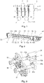
- the figure 1 shows a device 1, which is specially designed for cleaning a metal strip B here.
- the device 1 has a plurality of rollers 2 over which the metal strip B is transported in a zigzag fashion along a transport direction T.
- the device 1 has two surge nozzles 10 between which the metal strip B passes and facing each other in a manner (described in detail below) such that both surfaces of the metal strip B can be contacted with an aqueous electrolyte.
- the metal strip B runs through the space between the two surge nozzles 10, preferably vertically, in the descending transport direction. Alternatively or additionally using further surge nozzles, the metal strip B can also pass these in the ascending direction of transport.
- an alternating voltage is applied between the metal strip B and the electrodes (described in detail below) of the surge nozzles 10 .
- the device 1 has a power supply 3 which is set up to provide and apply the AC voltage.
- the power supply is electrically connected to the electrodes of the surge nozzles 10 and the metal strip B, for example via a conductive roller 2 .
- the electrolyte which is a cleaning liquid or cleaning solution, is an alkaline solution, for example.
- the dip pole plates P are immersed in an electrolyte bath in order to achieve an electrolytic cleaning effect when a voltage is applied between the dip pole plates P and the metal strip B.
- the partial representation of this conventional principle in the figure 1 serves to show the retrofitting of a conventional system. The conventional transport path of the metal strip B can thus be retained.
- the conventional dipping pole plates P and/or other components of the conventional system do not necessarily have to be dismantled, which means that conversion costs can be saved.
- the dipping pole plates P are deactivated, and an electrolyte bath is also dispensed with, since the cleaning is carried out solely by the surge nozzles 10 .
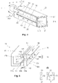
- the figure 2 shows in perspective such a surge nozzle 10 and its suspension or storage.
- the surge nozzle 10 has an elongate, for example cuboid, base body 20 .
- the base body 20 has one or more channels through which an electrolyte, supplied via tubes 11, flows and is distributed along the longitudinal extent of the surge nozzle 10.
- the base body 20 is hollow, as can be seen from the Figures 4 and 5 emerges.
- the base body 20 has one or more outlet openings 21 (cf. figure 4 ) through which the electrolyte can escape laterally from the base body 20.
- the base body 20 is made of a non-conductive material, preferably plastic.
- the surge nozzle 10 also has a surge opening 30, which is preferably a slit.
- the surge opening 30 can be formed by two nozzle plates 31 each having an elongated nozzle lip 32 facing each other, as in FIG figure 2 shown.
- the nozzle plates 31 are fastened to the base body 20 in such a way that the electrolyte exiting via the outlet opening 21 is discharged to the outside through the surge opening 30 .
- the two nozzle plates 31 are preferably designed to be adjustable, for example by being fitted with slotted holes 33 and corresponding screws 34 (cf. figure 5 ) are connected to the base body 20 and can be moved in such a way that the distance between the two nozzle lips 32, and thus the slot width, is adjustable.
- the nozzle plates 31 are made of a non-conductive material, preferably plastic. Due to their shape, the nozzle lips 32 decisively determine the shape or nature of the surge of electrolyte emerging through the nozzle opening 30 . For this reason, the nozzle plates 31 with their nozzle lips 32 are preferably provided to be exchangeable.
- An electrode 40 is provided between the base body 20 and the nozzle plates 31, which electrode has two electrode sections 40a and 40b in the present example.
- the position of the electrode sections 40a, 40b is particularly clear from the figure 5 and is described in detail below.
- the liquid electrolyte before it emerges from the surge opening 30, comes into contact with the electrode sections 40a, 40b.
- an AC voltage is applied between the electrode sections 40a, 40b and the metal strip B, which results in an ion current in the electrolyte, as a result of which the electrolytic cleaning effect on the surfaces of the metal strip B is achieved.
- the figure 2 shows an exemplary suspension or mounting of the same next to the surge nozzle 10 .
- the tubes 11 which are connected to the base body 20 on both sides (seen in the longitudinal direction), are held in a storage device 50 .
- the figure 3 shows an enlarged detail of the storage device 50, wherein two surge nozzles 10 are arranged with their surge openings 30 facing each other.
- the surge nozzles 10 are mounted such that they can be rotated or adjusted about their longitudinal axes, in that the tubes 11 are held, for example, by a detachable clamp 51 each.
- the storage can also be realized in other ways.
- the adjustability of the surge nozzle 10 or parts thereof along one or more degrees of freedom can be realized automatically by means of actuators (such as electric, magnetic, hydraulic, pneumatic, etc.). This also applies, for example, to the adjustability of the nozzle plates 31.
- the storage device 50 can have a screwable flange plate (no reference number), whereby the surge nozzle 10 in a simple manner from Cleaning tank can be decoupled. In this way, the surge nozzle 10 can be removed from the side of the cleaning tank for maintenance and repair work without dismantling other tank installations.
- Conventional taupole plates P can only be removed via the top space of the cleaning tank and thus require a time-consuming dismantling of the existing tank installations in the top space.
- FIGS. 4 and 5 12 are three-dimensional sectional views of an exemplary surge nozzle 10, with the section being taken perpendicular to the longitudinal axis. In the figure 5 the components are shown partially exploded.
- the electrode sections 40a, 40b extend essentially over the entire length of the base body 20 and are located on the side of the outlet opening 21.
- the electrode sections 40a, 40b also form an outlet opening 41 through which the electrolyte is discharged to the surge opening 30 and then to the outside .
- the electrode sections 40a, 40b each have a longitudinal edge 42a, 42b, which run parallel and form the outlet opening 41 as a slit. It should be pointed out that the electrode sections 40a, 40b can also be designed in a different way, for example as a one-piece electrode.
- the electrode sections 40a, 40b overlap the exit opening 21 of the base body 20 in such a way that the electrolyte comes into contact with them when exiting.
- the longitudinal edges 42a, 42b protrude beyond the corresponding longitudinal edges 21a, 21b of the outlet opening 21.
- the slit-like exit opening 21 of the base body 20 is narrower than the slit-like exit opening 41 formed by the two electrode sections 40a, 40b.
- the overlap distance d which denotes the distance between the longitudinal edge 42a of the electrode section 40a and the associated longitudinal edge 21a of the outlet opening 21 (analogous to longitudinal edges 42b and 21b) in the plane of the electrode 40, is in the range of 10 to 30 mm, for example, specifically approximately at 20mm.
- the slit-like surge opening 30 coincides with the outlet opening 41 or is narrower than this.
- the distance s between the nozzle lips 32 is preferably in the range from 2 to 6 mm, as a result of which a surge of electrolyte with a relatively low pressure can be achieved.
- the base body 20 can have a length of approximately 1,200 mm, for example.
- the nozzle lips 32 can be shaped differently for the direction and shape of the electrolyte surge, as can be seen from the figure section 5(I).
- the electrode sections 40a, 40b can each be stamped out of sheet metal and each have a connection section 43a and 43b, via which the electrode sections 40a, 40b are electrically contacted.
- the connection section 43a, 43b can be formed, for example, by bending over a sheet metal section of the electrode sections 40a, 40b and can have an opening for a screw connection.
- the positions of the two connecting sections 43a, 43b are preferably chosen in such a way that the most homogeneous possible treatment result is achieved. In the present exemplary embodiment, this is achieved in that the two connection sections 43a, 43b are arranged on opposite sides of the electrode sections 40a, 40b, viewed along the longitudinal extent of the surge nozzle 10. In this case, any electrical interference and influencing variables are compensated.
- the position and nature of the electrode sections 40a, 40b relative to the base body 20 is particularly clear from the three-dimensional representation of figure 6 emerges, in which the nozzle plates 31 are omitted.
- the surge nozzle 10, in particular its surge opening 30, is designed in such a way that the electrolyte can be discharged with a low pressure in comparison to conventional high-pressure nozzles.
- the electrolyte is brought into contact with the metal strip B as a gush.
- the electrolyte has a pressure of less than 100 mbar.
- an AC voltage is applied between the electrode sections 40a, 40b and the metal strip B, whereby not only a uniform cleaning of both sides of the metal strip B but also the electrolytic cleaning effect is achieved with a comparatively low energy consumption.
- the two-sided cleaning is preferably carried out simultaneously and at the same "place", i.e. there is no local and no time offset in the cleaning activities of the two sides of the belt. This contributes to a homogeneous cleaning result.
- the surge nozzles 10 presented here are particularly preferred for use in electrolytic cleaning lines for strip systems. They form an improved technique for substituting dip pole plates P and/or electrolytically acting high-pressure cleaning nozzles. “Cleaning” is understood here to mean in particular the removal of surface coatings such as metal particles (Fe/Al fines), oil and grease contamination, anti-corrosion oils, lubricating oils and/or deep-drawing aids that reduce the coefficient of friction.
- surface coatings such as metal particles (Fe/Al fines), oil and grease contamination, anti-corrosion oils, lubricating oils and/or deep-drawing aids that reduce the coefficient of friction.
- High current densities can be achieved on the metal strip B to be treated as a result of the surge-like ejection of the electrolyte, ie the ejection of the electrolyte at a pressure which is low in comparison with conventional high-pressure nozzles.
- the current at the electrode sections 40a, 40b is approximately 800 A with an applied voltage of approximately 20 V. This leads to a increased activity of the cleaning solution due to stronger turbulence and better mixing.
- the cleaning solution acts on a comparatively thin boundary layer in the transition between the cleaning solution and the strip surface, as a result of which the electrical current losses can be reduced.
- the specific energy consumption can be reduced.
Landscapes
- Chemical & Material Sciences (AREA)
- Engineering & Computer Science (AREA)
- Chemical Kinetics & Catalysis (AREA)
- Electrochemistry (AREA)
- Materials Engineering (AREA)
- Metallurgy (AREA)
- Organic Chemistry (AREA)
- Electroplating Methods And Accessories (AREA)
- Cleaning And De-Greasing Of Metallic Materials By Chemical Methods (AREA)
Claims (12)
- Dispositif (1) destiné au traitement électrolytique, de préférence à un nettoyage par voie électrolytique d'une bande métallique (B) qui peut être transportée le long d'une direction de transport (T) en passant par un tronçon de traitement du dispositif (1) ; dans lequel le dispositif (1) présente :au moins deux buses de pulvérisation (10) qui sont disposées de façon appariée d'une manière telle que le tronçon de traitement se trouve entre deux buses de pulvérisation (10) qui sont disposées de façon appariée ;dans lequel chacune des buses de pulvérisation (10) présente une ouverture de pulvérisation (30) et une électrode (40), en étant conçue en outre dans le but de mettre un liquide de traitement de type électrolytique en contact avec l'électrode correspondante (40), de distribuer le liquide en question à partir de l'ouverture de projection correspondante (30) et de l'appliquer dans le tronçon de traitement sur au moins une surface de la bande métallique (B) ; etles ouvertures de projection (30) de deux buses de pulvérisation (10) qui sont disposées de façon appariée sont tournées l'une vers l'autre d'une manière telle que la bande métallique (B) qui passe par le tronçon de traitement peut être sollicitée sur ses deux côtés avec le liquide de traitement ;caractérisé par une alimentation en courant (3) qui est conçue dans le but d'appliquer une tension alternative entre la bande métallique (B) et les électrodes (40) de chacune des buses de pulvérisation (10).
- Dispositif (1) conformément à la revendication 1, caractérisé en ce que le dispositif en question est conçu d'une manière telle que la bande métallique (B) passe par le tronçon de traitement dans une position verticale.
- Dispositif (1) conformément à l'une quelconque des revendications précédentes, caractérisé en ce que chacune des buses de pulvérisation (10) présente un corps de base (20) de forme oblongue qui comprend au moins une ouverture d'évacuation (21), de préférence sous la forme d'une fente, le long de l'étendue longitudinale du corps de base (20) ; dans lequel l'électrode (40) est appliquée contre le côté externe du corps de base (20) d'une manière telle qu'elle chevauche l'ouverture d'évacuation (21) tant et si bien que le liquide de traitement qui sort en passant par l'ouverture d'évacuation (21) entre en contact avec l'électrode (40).
- Dispositif (1) conformément à la revendication 3, caractérisé en ce que l'électrode (40) présente deux tronçons d'électrode (40a, 40b) qui présentent chacun une arête longitudinale (42a, 42b) qui sont tournées l'une vers l'autre d'une manière telle qu'elles forment une ouverture d'évacuation (41) sous la forme d'une fente.
- Dispositif (1) conformément à la revendication 4, caractérisé en ce que les tronçons d'électrode (40a, 40b) présentent respectivement un tronçon de raccordement (43a, 43b) à des fins de mise en contact par voie électrique ; dans lequel les deux tronçons de raccordement (43a, 43b) sont disposés sur des côtés opposés des tronçons d'électrode (40a, 40b), lorsqu'on regarde dans la direction de l'étendue longitudinale de la buse de pulvérisation (10).
- Dispositif (1) conformément à l'une quelconque des revendications 3 à 5, caractérisé en ce que chacune des buses de pulvérisation (10) présente en outre au moins une plaque de buse (31) qui forme l'ouverture de pulvérisation (30) et qui est appliquée sur le côté externe du corps de base (20) tant et si bien que l'électrode (40) se trouve entre le corps de base (20) et la plaque de buse (31).
- Dispositif (1) conformément à la revendication 6, caractérisé en ce que chacune des buses de pulvérisation (10) présente deux plaques de buses (31), qui possèdent respectivement une lèvre de buse (32) qui sont tournées l'une vers l'autre, d'une manière telle que l'ouverture de pulvérisation (30) est réalisée sous la forme d'une fente entre les lèvres de buses (32) ; dans lequel les plaques de buses (31) présentent de préférence des trous (33) de forme oblongue, par l'intermédiaire desquels les plaques de buse (31) peuvent être appliquées de manière à pouvoir se déplacer au moyen de vis (34) contre le corps de base (20) et/ou contre l'électrode (40).
- Dispositif (1) conformément à l'une quelconque des revendications précédentes, caractérisé en ce que chacune des buses de pulvérisation (10) est maintenue en rotation autour de leur axe longitudinal.
- Procédé destiné au traitement électrolytique, de préférence à un nettoyage par voie électrolytique, d'une bande métallique (B) qui peut être transportée long d'une direction de transport (T) en passant par un tronçon de traitement ; dans lequel le procédé est mis en œuvre avec un dispositif (1) en conformité avec l'une quelconque des revendications 1 à 9 et présente :la mise en contact d'un liquide de traitement par voie électrolytique avec l'électrode (40) de chacune des buses de pulvérisation (10) ;la distribution du liquide de traitement à partir de l'ouverture de pulvérisation (30) de chacune des buses de pulvérisation (10) ; etl'application du liquide de traitement dans le tronçon de traitement sur une surface correspondante de la bande métallique (B) d'une manière telle que la bande métallique (B) qui passe par le tronçon de traitement est sollicitée sur ses deux côtés avec le liquide de traitement ;caractérisé en ce queune tension alternative est appliquée entre l'électrode (40) et la bande métallique (B).
- Procédé conformément à la revendication 9, caractérisé en ce que la bande métallique (B) est transportée à travers le tronçon de traitement dans une position verticale.
- Procédé conformément à la revendication 9 ou 10, caractérisé en ce que le liquide de traitement est appliqué sur la bande métallique (B) avec une pression qui est inférieure à 100 mbar.
- Procédé conformément à l'une quelconque des revendications 9 à 11, caractérisé en ce que le liquide de traitement est une solution alcaline.
Applications Claiming Priority (2)
| Application Number | Priority Date | Filing Date | Title |
|---|---|---|---|
| DE102018201015 | 2018-01-23 | ||
| DE102018215809.6A DE102018215809A1 (de) | 2018-01-23 | 2018-09-18 | Vorrichtung und Verfahren zur elektrolytischen Behandlung eines Metallbandes |
Publications (3)
| Publication Number | Publication Date |
|---|---|
| EP3514263A2 EP3514263A2 (fr) | 2019-07-24 |
| EP3514263A3 EP3514263A3 (fr) | 2019-10-16 |
| EP3514263B1 true EP3514263B1 (fr) | 2022-11-09 |
Family
ID=65199323
Family Applications (1)
| Application Number | Title | Priority Date | Filing Date |
|---|---|---|---|
| EP19152914.8A Active EP3514263B1 (fr) | 2018-01-23 | 2019-01-21 | Dispositif et procédé de traitement électrolytique d'une bande métallique |
Country Status (2)
| Country | Link |
|---|---|
| EP (1) | EP3514263B1 (fr) |
| ES (1) | ES2937690T3 (fr) |
Citations (1)
| Publication number | Priority date | Publication date | Assignee | Title |
|---|---|---|---|---|
| DE3108615C2 (de) * | 1980-03-07 | 1984-09-27 | Nippon Steel Corp., Tokio / Tokyo | Vorrichtung und Verfahren zum elektrolytischen Behandeln eines Metallbandes |
Family Cites Families (8)
| Publication number | Priority date | Publication date | Assignee | Title |
|---|---|---|---|---|
| JPH05195300A (ja) * | 1992-01-23 | 1993-08-03 | Fuji Photo Film Co Ltd | 電解処理装置 |
| DE69803138T2 (de) | 1997-04-10 | 2002-11-14 | Hotani Kk | Verfahren und Vorrichtung zur Reinigung von Metallbändern |
| JP3705527B2 (ja) * | 1998-04-02 | 2005-10-12 | 富士写真フイルム株式会社 | 平版印刷版用支持体の電解処理装置 |
| DE19844832A1 (de) * | 1998-09-30 | 2000-04-13 | Kai Greising | Verfahren und Vorrichtung zum Reinigen von Metalloberflächen |
| DE10210538B4 (de) | 2002-03-05 | 2004-11-18 | Atotech Deutschland Gmbh | Horizontal-Durchlaufanlage und Verfahren zum galvanotechnischen Behandeln von Behandlungsgut |
| DE10212436B4 (de) | 2002-03-21 | 2005-03-03 | Sms Demag Ag | Vorrichtung zur Behandlung von strangförmigem metallischen Gut und ihre Verwendung |
| JP2004268517A (ja) * | 2003-03-11 | 2004-09-30 | Fuji Photo Film Co Ltd | 平版印刷版支持体の製造方法 |
| JP2011246790A (ja) * | 2010-05-28 | 2011-12-08 | Nippon Steel Corp | 金属帯の連続電解エッチング方法及び連続電解エッチング装置 |
-
2019
- 2019-01-21 ES ES19152914T patent/ES2937690T3/es active Active
- 2019-01-21 EP EP19152914.8A patent/EP3514263B1/fr active Active
Patent Citations (1)
| Publication number | Priority date | Publication date | Assignee | Title |
|---|---|---|---|---|
| DE3108615C2 (de) * | 1980-03-07 | 1984-09-27 | Nippon Steel Corp., Tokio / Tokyo | Vorrichtung und Verfahren zum elektrolytischen Behandeln eines Metallbandes |
Also Published As
| Publication number | Publication date |
|---|---|
| EP3514263A3 (fr) | 2019-10-16 |
| EP3514263A2 (fr) | 2019-07-24 |
| ES2937690T3 (es) | 2023-03-30 |
Similar Documents
| Publication | Publication Date | Title |
|---|---|---|
| DE102012018393B4 (de) | Serielles Galvanisierungssystem | |
| EP1828441B1 (fr) | Installation d'application de peinture electrophoretique par immersion | |
| WO1998049374A2 (fr) | Dispositif de traitement electrolytique de carte de circuits et de feuilles conductrices | |
| EP0059787B1 (fr) | Appareil pour couvrir d'une couche mince des pièces électroconductrices composées de bandes, de rubans ou analogues pour un procédé éléctrolytrique en continu | |
| EP1007766B1 (fr) | Dispositif et procede pour egaliser l'epaisseur de couches metalliques au niveau des points de mise en contact electriques sur un produit a traiter | |
| DE3108615C2 (de) | Vorrichtung und Verfahren zum elektrolytischen Behandeln eines Metallbandes | |
| DE19713647A1 (de) | Vorrichtung zum galvanischen Abscheiden eines ein- oder beidseitigen Metall- oder Legierungsüberzuges auf einem Metallband | |
| WO1995020692A1 (fr) | Procede et dispositif de metallisation ou d'attaque electrolytiques d'articles a traiter | |
| DE3440457C2 (de) | Vorrichtung zur kontinuierlichen elektrolytischen Abscheidung einer Abdeckmetallschicht auf einem Metallband und Verwendung einer solchen Vorrichtung | |
| DE3246574C2 (de) | Vorrichtung zur elektrostatischen Spritzlackierung | |
| DE19717489B4 (de) | Anordnung zur elektrogalvanischen Metallbeschichtung eines Bandes | |
| EP3514263B1 (fr) | Dispositif et procédé de traitement électrolytique d'une bande métallique | |
| EP0038447A1 (fr) | Dispositif pour le dépôt partiel par voie électrolytique de surfaces conductrices ou de surfaces rendues conductrices | |
| DE19633797B4 (de) | Vorrichtung zum Galvanisieren von elektronischen Leiterplatten oder dergleichen | |
| DE102018215809A1 (de) | Vorrichtung und Verfahren zur elektrolytischen Behandlung eines Metallbandes | |
| DE4127740C2 (fr) | ||
| WO1998007904A1 (fr) | Dispositif de galvanoplastie de cartes de circuits | |
| EP0454710A1 (fr) | Procede de deposition par electrolyse de metaux sur une face ou sur les deux faces de bandes. | |
| DE4103171C1 (fr) | ||
| DE2548414A1 (de) | Verfahren und vorrichtung zur elektrophoretischen beschichtung von gegenstaenden | |
| DE60302560T2 (de) | Durchlaufmetallisierungsanlage und verfahren zum elektrolytischen metallisieren von werkstücken | |
| DE3423734C1 (de) | Anlage zur elektrolytischen Oberflaechenbeschichtung eines Metallbandes,insbesondere zur Verzinkung von Stahlband | |
| DE102004025827B3 (de) | Vorrichtung zum elektrischen Kontaktieren von ebenem Behandlungsgut in Durchlaufanlagen | |
| EP3015573B1 (fr) | Système pour galvaniser une bande | |
| DE10228400B4 (de) | Vorrichtung zum Galvanisieren von elektronischen Leiterplatten |
Legal Events
| Date | Code | Title | Description |
|---|---|---|---|
| PUAI | Public reference made under article 153(3) epc to a published international application that has entered the european phase |
Free format text: ORIGINAL CODE: 0009012 |
|
| STAA | Information on the status of an ep patent application or granted ep patent |
Free format text: STATUS: REQUEST FOR EXAMINATION WAS MADE |
|
| 17P | Request for examination filed |
Effective date: 20190121 |
|
| AK | Designated contracting states |
Kind code of ref document: A2 Designated state(s): AL AT BE BG CH CY CZ DE DK EE ES FI FR GB GR HR HU IE IS IT LI LT LU LV MC MK MT NL NO PL PT RO RS SE SI SK SM TR |
|
| AX | Request for extension of the european patent |
Extension state: BA ME |
|
| PUAL | Search report despatched |
Free format text: ORIGINAL CODE: 0009013 |
|
| AK | Designated contracting states |
Kind code of ref document: A3 Designated state(s): AL AT BE BG CH CY CZ DE DK EE ES FI FR GB GR HR HU IE IS IT LI LT LU LV MC MK MT NL NO PL PT RO RS SE SI SK SM TR |
|
| AX | Request for extension of the european patent |
Extension state: BA ME |
|
| RIC1 | Information provided on ipc code assigned before grant |
Ipc: C25F 7/00 20060101AFI20190906BHEP Ipc: C25F 1/00 20060101ALI20190906BHEP |
|
| STAA | Information on the status of an ep patent application or granted ep patent |
Free format text: STATUS: EXAMINATION IS IN PROGRESS |
|
| 17Q | First examination report despatched |
Effective date: 20191122 |
|
| RBV | Designated contracting states (corrected) |
Designated state(s): AL AT BE BG CH CY CZ DE DK EE ES FI FR GB GR HR HU IE IS IT LI LT LU LV MC MK MT NL NO PL PT RO RS SE SI SK SM TR |
|
| STAA | Information on the status of an ep patent application or granted ep patent |
Free format text: STATUS: EXAMINATION IS IN PROGRESS |
|
| GRAP | Despatch of communication of intention to grant a patent |
Free format text: ORIGINAL CODE: EPIDOSNIGR1 |
|
| STAA | Information on the status of an ep patent application or granted ep patent |
Free format text: STATUS: GRANT OF PATENT IS INTENDED |
|
| INTG | Intention to grant announced |
Effective date: 20220523 |
|
| GRAS | Grant fee paid |
Free format text: ORIGINAL CODE: EPIDOSNIGR3 |
|
| GRAA | (expected) grant |
Free format text: ORIGINAL CODE: 0009210 |
|
| STAA | Information on the status of an ep patent application or granted ep patent |
Free format text: STATUS: THE PATENT HAS BEEN GRANTED |
|
| AK | Designated contracting states |
Kind code of ref document: B1 Designated state(s): AL AT BE BG CH CY CZ DE DK EE ES FI FR GB GR HR HU IE IS IT LI LT LU LV MC MK MT NL NO PL PT RO RS SE SI SK SM TR |
|
| REG | Reference to a national code |
Ref country code: GB Ref legal event code: FG4D Free format text: NOT ENGLISH |
|
| REG | Reference to a national code |
Ref country code: CH Ref legal event code: EP Ref country code: AT Ref legal event code: REF Ref document number: 1530417 Country of ref document: AT Kind code of ref document: T Effective date: 20221115 |
|
| REG | Reference to a national code |
Ref country code: DE Ref legal event code: R096 Ref document number: 502019006180 Country of ref document: DE |
|
| REG | Reference to a national code |
Ref country code: IE Ref legal event code: FG4D Free format text: LANGUAGE OF EP DOCUMENT: GERMAN |
|
| REG | Reference to a national code |
Ref country code: LT Ref legal event code: MG9D |
|
| REG | Reference to a national code |
Ref country code: NL Ref legal event code: MP Effective date: 20221109 |
|
| REG | Reference to a national code |
Ref country code: ES Ref legal event code: FG2A Ref document number: 2937690 Country of ref document: ES Kind code of ref document: T3 Effective date: 20230330 |
|
| PG25 | Lapsed in a contracting state [announced via postgrant information from national office to epo] |
Ref country code: SE Free format text: LAPSE BECAUSE OF FAILURE TO SUBMIT A TRANSLATION OF THE DESCRIPTION OR TO PAY THE FEE WITHIN THE PRESCRIBED TIME-LIMIT Effective date: 20221109 Ref country code: PT Free format text: LAPSE BECAUSE OF FAILURE TO SUBMIT A TRANSLATION OF THE DESCRIPTION OR TO PAY THE FEE WITHIN THE PRESCRIBED TIME-LIMIT Effective date: 20230309 Ref country code: NO Free format text: LAPSE BECAUSE OF FAILURE TO SUBMIT A TRANSLATION OF THE DESCRIPTION OR TO PAY THE FEE WITHIN THE PRESCRIBED TIME-LIMIT Effective date: 20230209 Ref country code: LT Free format text: LAPSE BECAUSE OF FAILURE TO SUBMIT A TRANSLATION OF THE DESCRIPTION OR TO PAY THE FEE WITHIN THE PRESCRIBED TIME-LIMIT Effective date: 20221109 Ref country code: FI Free format text: LAPSE BECAUSE OF FAILURE TO SUBMIT A TRANSLATION OF THE DESCRIPTION OR TO PAY THE FEE WITHIN THE PRESCRIBED TIME-LIMIT Effective date: 20221109 |
|
| PGFP | Annual fee paid to national office [announced via postgrant information from national office to epo] |
Ref country code: FR Payment date: 20230124 Year of fee payment: 5 |
|
| PG25 | Lapsed in a contracting state [announced via postgrant information from national office to epo] |
Ref country code: RS Free format text: LAPSE BECAUSE OF FAILURE TO SUBMIT A TRANSLATION OF THE DESCRIPTION OR TO PAY THE FEE WITHIN THE PRESCRIBED TIME-LIMIT Effective date: 20221109 Ref country code: PL Free format text: LAPSE BECAUSE OF FAILURE TO SUBMIT A TRANSLATION OF THE DESCRIPTION OR TO PAY THE FEE WITHIN THE PRESCRIBED TIME-LIMIT Effective date: 20221109 Ref country code: LV Free format text: LAPSE BECAUSE OF FAILURE TO SUBMIT A TRANSLATION OF THE DESCRIPTION OR TO PAY THE FEE WITHIN THE PRESCRIBED TIME-LIMIT Effective date: 20221109 Ref country code: IS Free format text: LAPSE BECAUSE OF FAILURE TO SUBMIT A TRANSLATION OF THE DESCRIPTION OR TO PAY THE FEE WITHIN THE PRESCRIBED TIME-LIMIT Effective date: 20230309 Ref country code: HR Free format text: LAPSE BECAUSE OF FAILURE TO SUBMIT A TRANSLATION OF THE DESCRIPTION OR TO PAY THE FEE WITHIN THE PRESCRIBED TIME-LIMIT Effective date: 20221109 Ref country code: GR Free format text: LAPSE BECAUSE OF FAILURE TO SUBMIT A TRANSLATION OF THE DESCRIPTION OR TO PAY THE FEE WITHIN THE PRESCRIBED TIME-LIMIT Effective date: 20230210 |
|
| PGFP | Annual fee paid to national office [announced via postgrant information from national office to epo] |
Ref country code: IT Payment date: 20230228 Year of fee payment: 5 Ref country code: BE Payment date: 20230119 Year of fee payment: 5 |
|
| PG25 | Lapsed in a contracting state [announced via postgrant information from national office to epo] |
Ref country code: NL Free format text: LAPSE BECAUSE OF FAILURE TO SUBMIT A TRANSLATION OF THE DESCRIPTION OR TO PAY THE FEE WITHIN THE PRESCRIBED TIME-LIMIT Effective date: 20221109 |
|
| PG25 | Lapsed in a contracting state [announced via postgrant information from national office to epo] |
Ref country code: SM Free format text: LAPSE BECAUSE OF FAILURE TO SUBMIT A TRANSLATION OF THE DESCRIPTION OR TO PAY THE FEE WITHIN THE PRESCRIBED TIME-LIMIT Effective date: 20221109 Ref country code: RO Free format text: LAPSE BECAUSE OF FAILURE TO SUBMIT A TRANSLATION OF THE DESCRIPTION OR TO PAY THE FEE WITHIN THE PRESCRIBED TIME-LIMIT Effective date: 20221109 Ref country code: EE Free format text: LAPSE BECAUSE OF FAILURE TO SUBMIT A TRANSLATION OF THE DESCRIPTION OR TO PAY THE FEE WITHIN THE PRESCRIBED TIME-LIMIT Effective date: 20221109 Ref country code: DK Free format text: LAPSE BECAUSE OF FAILURE TO SUBMIT A TRANSLATION OF THE DESCRIPTION OR TO PAY THE FEE WITHIN THE PRESCRIBED TIME-LIMIT Effective date: 20221109 Ref country code: CZ Free format text: LAPSE BECAUSE OF FAILURE TO SUBMIT A TRANSLATION OF THE DESCRIPTION OR TO PAY THE FEE WITHIN THE PRESCRIBED TIME-LIMIT Effective date: 20221109 |
|
| REG | Reference to a national code |
Ref country code: DE Ref legal event code: R097 Ref document number: 502019006180 Country of ref document: DE |
|
| P01 | Opt-out of the competence of the unified patent court (upc) registered |
Effective date: 20230707 |
|
| PG25 | Lapsed in a contracting state [announced via postgrant information from national office to epo] |
Ref country code: SK Free format text: LAPSE BECAUSE OF FAILURE TO SUBMIT A TRANSLATION OF THE DESCRIPTION OR TO PAY THE FEE WITHIN THE PRESCRIBED TIME-LIMIT Effective date: 20221109 Ref country code: AL Free format text: LAPSE BECAUSE OF FAILURE TO SUBMIT A TRANSLATION OF THE DESCRIPTION OR TO PAY THE FEE WITHIN THE PRESCRIBED TIME-LIMIT Effective date: 20221109 |
|
| REG | Reference to a national code |
Ref country code: CH Ref legal event code: PL |
|
| PLBE | No opposition filed within time limit |
Free format text: ORIGINAL CODE: 0009261 |
|
| STAA | Information on the status of an ep patent application or granted ep patent |
Free format text: STATUS: NO OPPOSITION FILED WITHIN TIME LIMIT |
|
| PG25 | Lapsed in a contracting state [announced via postgrant information from national office to epo] |
Ref country code: LU Free format text: LAPSE BECAUSE OF NON-PAYMENT OF DUE FEES Effective date: 20230121 |
|
| 26N | No opposition filed |
Effective date: 20230810 |
|
| GBPC | Gb: european patent ceased through non-payment of renewal fee |
Effective date: 20230209 |
|
| PG25 | Lapsed in a contracting state [announced via postgrant information from national office to epo] |
Ref country code: LI Free format text: LAPSE BECAUSE OF NON-PAYMENT OF DUE FEES Effective date: 20230131 Ref country code: CH Free format text: LAPSE BECAUSE OF NON-PAYMENT OF DUE FEES Effective date: 20230131 |
|
| PG25 | Lapsed in a contracting state [announced via postgrant information from national office to epo] |
Ref country code: SI Free format text: LAPSE BECAUSE OF FAILURE TO SUBMIT A TRANSLATION OF THE DESCRIPTION OR TO PAY THE FEE WITHIN THE PRESCRIBED TIME-LIMIT Effective date: 20221109 |
|
| PG25 | Lapsed in a contracting state [announced via postgrant information from national office to epo] |
Ref country code: GB Free format text: LAPSE BECAUSE OF NON-PAYMENT OF DUE FEES Effective date: 20230209 |
|
| PG25 | Lapsed in a contracting state [announced via postgrant information from national office to epo] |
Ref country code: IE Free format text: LAPSE BECAUSE OF NON-PAYMENT OF DUE FEES Effective date: 20230121 Ref country code: GB Free format text: LAPSE BECAUSE OF NON-PAYMENT OF DUE FEES Effective date: 20230209 |
|
| PGFP | Annual fee paid to national office [announced via postgrant information from national office to epo] |
Ref country code: ES Payment date: 20240227 Year of fee payment: 6 |
|
| PGFP | Annual fee paid to national office [announced via postgrant information from national office to epo] |
Ref country code: AT Payment date: 20240122 Year of fee payment: 6 |
|
| PGFP | Annual fee paid to national office [announced via postgrant information from national office to epo] |
Ref country code: DE Payment date: 20240119 Year of fee payment: 6 |