EP3511753A1 - Module d'épissure à libération de câble - Google Patents
Module d'épissure à libération de câble Download PDFInfo
- Publication number
- EP3511753A1 EP3511753A1 EP18020013.1A EP18020013A EP3511753A1 EP 3511753 A1 EP3511753 A1 EP 3511753A1 EP 18020013 A EP18020013 A EP 18020013A EP 3511753 A1 EP3511753 A1 EP 3511753A1
- Authority
- EP
- European Patent Office
- Prior art keywords
- cable
- splice
- guide
- stop
- fiber optic
- Prior art date
- Legal status (The legal status is an assumption and is not a legal conclusion. Google has not performed a legal analysis and makes no representation as to the accuracy of the status listed.)
- Granted
Links
- 239000000835 fiber Substances 0.000 claims abstract description 25
- 238000005452 bending Methods 0.000 claims description 11
- 239000013307 optical fiber Substances 0.000 claims description 7
- 230000003247 decreasing effect Effects 0.000 claims 1
- 238000000465 moulding Methods 0.000 description 2
- 229910000831 Steel Inorganic materials 0.000 description 1
- 230000008901 benefit Effects 0.000 description 1
- 230000005540 biological transmission Effects 0.000 description 1
- 230000008859 change Effects 0.000 description 1
- 230000006835 compression Effects 0.000 description 1
- 238000007906 compression Methods 0.000 description 1
- 230000008878 coupling Effects 0.000 description 1
- 238000010168 coupling process Methods 0.000 description 1
- 238000005859 coupling reaction Methods 0.000 description 1
- 230000007423 decrease Effects 0.000 description 1
- 230000001419 dependent effect Effects 0.000 description 1
- 238000006073 displacement reaction Methods 0.000 description 1
- 238000005516 engineering process Methods 0.000 description 1
- 230000002349 favourable effect Effects 0.000 description 1
- 239000003365 glass fiber Substances 0.000 description 1
- 238000003780 insertion Methods 0.000 description 1
- 230000037431 insertion Effects 0.000 description 1
- 238000012423 maintenance Methods 0.000 description 1
- 230000007246 mechanism Effects 0.000 description 1
- 230000008054 signal transmission Effects 0.000 description 1
- 239000010959 steel Substances 0.000 description 1
Images

Classifications
-
- G—PHYSICS
- G02—OPTICS
- G02B—OPTICAL ELEMENTS, SYSTEMS OR APPARATUS
- G02B6/00—Light guides; Structural details of arrangements comprising light guides and other optical elements, e.g. couplings
- G02B6/44—Mechanical structures for providing tensile strength and external protection for fibres, e.g. optical transmission cables
- G02B6/4439—Auxiliary devices
- G02B6/444—Systems or boxes with surplus lengths
- G02B6/4453—Cassettes
- G02B6/4455—Cassettes characterised by the way of extraction or insertion of the cassette in the distribution frame, e.g. pivoting, sliding, rotating or gliding
Definitions
- the invention relates to a splice module for optical fiber cable ("fiber optic cable”). Such fiber optic cables are also known as fiber optic cables.
- Fiber optic cables are used for signal transmission with high transmission rates and / or high spatial range and are increasingly being used.
- the fiber optic cable networks are increasingly being laid to the consumer or even to the terminal in the home or office.
- With the increasing expansion of fiber optic cable networks is increasingly the task of connecting fiber optic cables with each other.
- the individual fibers are joined together using a technology known per se and these so-called splice and patch locations arranged in a manner also known per se and housed accessible and protected.
- Splice modules in which typically a plurality (e.g., twelve or a plurality of twelve) of optical fibers are spliced into cables each having a single optical fiber in respective splice cassettes and short connectors (pigtails) to termination members (such as connectors and couplings) are referred to. be guided. There can then be used to continue the fiber optic connections fiber optic cable with fasteners (such as plugs).
- fiber-optic cable thus refers to a cable type in the region of such a splice module and not to a "fiber-optic cable" buried under a road, for example, with a thick and varied bundle of individual fibers.
- known splice modules typically have a moving drawer-like drawer and a stationary support.
- the expression is not translational pull, but about a rotation axis, typically in the vicinity of the corner of the holder, swung open.
- Dreusezugelement that is, almost a Drehlade instead of a drawer.
- the translatory drawer movements lead to movements of the so-called patch cables, which are connected to the connecting elements of the connecting fibers. Such movements can lead to unwanted tensile loads or bending loads of individual fiber optic cables (patch cords). It should be noted in particular that the fiber optic cables should not fall below certain bending radii to avoid unwanted losses. Accordingly, guide structures are already known in the prior art, in which the affected patch cables are supported in the translatory extension or insertion of a drawer of elements that are typically at half the speed of the drawer, so translated, moved along.
- the invention has for its object to provide a solution with respect to the mechanical load on fiber optic cable solution for splice modules with Drezugszug instituten.
- the invention also relates to a module stack according to claim 9 and a distribution cabinet according to claim 10, each having a plurality of such splice modules.
- a basic idea of the invention consists in a stop which is firmly provided or attached to the pivotable part, that is to say on the rotary drawing element, and thus participates in its movements.
- This stop is in relation to a curvature described by a cable considered here, which runs from a connecting element, such as a plug connection element, towards a guide which is at least substantially fixed to the holder of the splicing module.
- a connecting element such as a plug connection element
- the stop is fixedly provided on the pivotable Dreusezugelement and thus does not require a complex mechanism for realizing a self-contained movement, as has been explained in relation to the prior art translational drawers.
- the invention is therefore very easy to implement and leads to reliable and resilient solutions.
- a counter-stop there is another stop member, referred to herein as a counter-stop, and accordingly provided on the other side of the cable under consideration and further away from the connecting member.
- a counter-stop which is also fixed with respect to the Dreusezugelements, ie with pivoting, it can be achieved when swinging it into the access position opposite to the previously described bending of the cable bend, so a total of a series of two (or more) opposing bends, in a sense an S-shape can be achieved.
- excess cable length can be "accommodated” when, upon pivoting into the access position, the distance between the connector and a guide of the cable on its way from the splice module is reduced away, which is typical of the splice modules considered.
- the counter-stop when pivoting further ensure that the cable in contact with the first-mentioned stop (on the other side of the cable) remains and thus to the other side an angular tolerance range following the connecting element (in the sense a distance away from the stop) is not exceeded.
- the stop according to the invention can prevent this by limiting the course of the cable subsequently to the connecting element and with respect to the direction predetermined thereby at an angle inwards.
- the cable on the connecting element also, if necessary, be protected by kink protection grommets and the described functions for limiting the cable angle there represent only an optional side of the invention.
- the stop and possibly also the counter-stop is formed with respect to the plane of the cable run in such a way that results in favorable round bends of the cable, ie with a radius of curvature of at least 30 mm.
- the form elements themselves, so the stop and / or the counter-stop not necessarily have exactly the same rounding, but may also for some reasons fluted, polygonal or otherwise deviating from a round shapes.
- a typical cable has some inherent rigidity and then goes around these shapes. It is, so to speak, an enveloping form.
- the constriction or opening can be at most three times, preferably twice the maximum possible number of individual cable diameters in the plane of the cable run.
- this guide itself can be movable in a certain way, so z. B. mounted with some play or about its own axis of rotation, preferably extending in the guide itself, be rotatable. However, it should not run with the pivoting movement in the sense of the same movement about the same pivot axis of rotation.
- the distance of the guide from the axis of rotation of the pivoting movement of the Dreerszugelements should preferably be at least 75% of the distance of the connecting element (or the wooachsen inconvenience connecting element) of the axis of rotation, the guide in the pivoted and pivoted state of the Drehauszugelements with respect to the axis of rotation of the pivoting movement rather the other side (relative to the connecting elements) is located.
- the angle formed by a connecting path between the guide and the axis of rotation on the one hand and on the other hand a connecting path between a respective connecting element and the axis of rotation should always be greater than 90 °.
- This guide has the purpose of locating the cable or cables locally to some extent before continuing to use, such as patch cords connected in the splice module.
- the already quoted EP 2 221 650 A1 shows a typical structure.
- the invention has hitherto been explained with reference to an optical fiber cable, whereby it is fundamentally suitable and preferred for splicing modules with a large number of such cables.
- a series of twelve or more connectors and cables may be provided in a rotary draw member.
- the optional statements on the angle limitation should preferably apply to at least the three rotational axis next connecting elements with the appropriate cable, preferably for at least the four or even five mosachsentext.
- the majority of the connecting elements is normally arranged in a linear row and the connecting elements increasingly move away from the axis of rotation in this row.
- the row is preferably coplanar with the plane of the rotary drawing element and the cable guide described herein.
- EP 2 221 650 A1 is a substantially rectangular base geometry of the Dreusezugelements with arrangement the axis of rotation in the vicinity of a front corner is preferred and also a change in the order of magnitude between 60 ° and 120 ° of the cable running direction of the direction predetermined by the connecting element to the through the guide through when pivoted Dreusezugelement.
- these two directions are substantially coplanar and also coplanar with the plane of the Dreerszugelements, which in turn is perpendicular to the axis of rotation.
- the "height" of the cable passage through the guide is approximately equal to that of the connector of this cable (with a preferred tolerance of ⁇ 20% of the distance between the connector and the guide in the pivoted state).
- the sweepable in the extension and Einschwenkterrorism the Dreusezugelements angle is preferably at least 90 ° and increasingly preferably at least 105 ° and 110 °.
- upper limits can be 120 °, 115 ° or 110 °. This angular range must be taken into account in the cable guide in the manner described here on the one hand and in particular the resulting cable lengths must be accommodated easily, on the other hand allow large Ausschwenkwinkel good accessibility of the splice module inside.
- stop and counter-stop can be supplemented in a preferred embodiment of the invention by walls which define between the stop and counter-stop on the respective sides of the cable between them a path through which the cable otherwise runs freely.
- the web width is at least twice a cable diameter.
- a stopper molding element which is constructed symmetrically in such a way that it is appropriate for each other, but in terms of the rotational axis position of the pivoting movement (front right or front left) each other mirrored splice modules is suitable, ie z. B. can be mounted mirror-inverted in the same way.
- the invention is preferably carried out for a plurality of splicing modules, which are realized in a serial manner as a stack, in particular in the direction of the axis of rotation lined up or stacked (that is, for example, horizontally or vertically).
- the splice modules can be housed in such a manner also in a known distribution cabinet, in particular in the described stacked design and in particular with a plurality of stacks therein. It may again be referred to the already cited prior art.
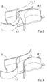
- Fig. 1 shows in plan view the (in the sense of Fig. 6 and 7 ) front right corner of a splice module according to the invention 1.
- a single fiber optic cable 2 is shown to facilitate the overview.
- up to 24 cables 2 can be patched in the splice module side-by-side Fig. 6 becomes clear, and Fig. 1 shows only six corresponding connector elements 3. These fasteners are used to connect the patch cable 2 shown here.
- Fig. 1 right side a guide 4 in the form of a comb element, the basis Fig. 7 can be seen more clearly.
- the housing has a total of a flat-box-like shape with approximately rectangular floor plan and takes a Dreerszugelement on the one hand carries the patch unit 5 with the connecting elements 3 and on the other hand, a front-side bar 14 and a in Fig. 1 a little above (ie behind) arranged front panel 13 are shown.
- the patch unit 5 is attached to the front panel 13. Furthermore, one recognizes the in the Fig. 1 and 2 on the drawing plane vertical (and in Fig. 8 vertically extending) axis of rotation A for the swiveling movement, which from the state in Fig. 1 to the in Fig. 2 leads.
- the inventive equipment of the splice module 1 relates to a fixedly attached to the front right corner of the Drehauszugelements mold part 8, in which for the cable 2 a stop 8.2 and a counter-stop 8.1 each with rounded shape (relative to the plane and thus the level of the cable 2) attached are. In between, a channel is guided between the wall regions of the element 8, which has approximately four times the width of the cable 2 shown, cf. also the Fig. 3 to 5 ,
- Fig. 1 can be seen in the pivoted state that the direction marked by the cross with the connecting element 3 (about 45 ° to the bottom right) is gradually left by the cable, the cable is pivoted by slightly more than 90 ° and in this orientation by the guide 4th running. In between, the cable passes the mold element 8, the channel formed therein and lies in particular against the stop 8.2 and the counter-stop 8.1. If accidentally pulled in this situation at the upper right end of the cable 2, the stop would 8.2 together with a not shown cable protection grommet prevent excessive deflection of the cable 2 of the predetermined by the connecting element 3 direction.
- the counter stop 8.1 enforces a second bend of the cable 2, which in opposite directions to the in Fig. 1 recognizable and adjoining the connecting element 3 there is a bend, so that a total of S between the connecting element 3 and the guide 4 is formed.
- This has the advantage that the existing cable length can be accommodated in the guide 4 without significant longitudinal movement or loading of the cable 2, namely, if the linear distance between the connecting element 3 and the guide 4 decreases due to the pivoting movement.
- the shaped element 8 as a whole, in particular in the area of stop 8.2 and counter stop 8.1, designed so that no radii of curvature of the cable below 30 mm occur.
- Fig. 1 and 2 It can also be seen that the two closer to the axis of rotation A connecting elements 3 and connected thereto (not shown) cable can be performed in a very similar manner and that this also applies to more distant from the axis of rotation A connecting elements 3 and 2 cable.
- Fig. 3 is a variant of the stopper element 8 from the Fig. 1 and 2 shown, with an upper-side cover 9.
- the cover 9 which may also be finger-shaped, includes a slot narrowing relative to the channel for the cables, through which individual cables can be routed in and out. However, because of its reduced width and its shape deviating from the centerline of the channel (and shaped in opposite directions to the ideal line of a taut cable), this slot prevents the cable 2 from slipping out automatically.
- Fig. 4 shows an analog representation Fig. 3 but with a stopper shaped element 8 cut open along a horizontal plane and slightly below the cover 9.
- the illustrated shape of the channel substantially corresponds to the one shown in FIG Fig. 1 and 2 ,
- Fig. 5 shows a plan view of the structure Fig. 4 with some dimensions.
- the drawn radii R of stop 8.2 and counter stop 8.1 are at least 30 mm and the channel width D is 15 mm in this example.
- a typical cable thickness is up to 2.4 mm.
- a typical length X is 110 mm and a typical depth Y is 85 mm.
- the height of the channel perpendicular to the drawing plane is 20 mm.
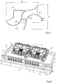
- Fig. 6 shows an open rotary tray of a splice module 1 with a cassette support plate 10 as a base and side walls 11 of bent sheet steel. This images 12 for vertically superposed splice cassettes for receiving the splices and the excess lengths of the glass fibers are shown.
- a cassette support plate 10 carries a further forward arranged cover plate 14 as a panel, wherein in the right part between the cover plate 14 and the front panel 13, the stopper molding element 8 provided is.
- Fig. 6 again shows the axis of rotation A (see. Fig. 1 and 2 ) in the right front area.
- the recordings 12 can accommodate two cassette stacks of six cassettes with two splices. These are assigned to the 24 connector elements 3.
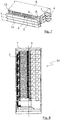
- Fig. 7 shows a stack of three such splice modules 1 according to Fig. 6 one above the other and in addition to the housing 6, the lateral guide 4, to the already in relation to the Fig. 1 and 2 was received and which has a comb-like structure. This results in connection with above and below further stacks or walls of the cabinet (see. Fig. 8 )
- a passage opening between the "comb teeth" of the guide 4 For each splice module 1, a passage opening between the "comb teeth" of the guide 4.
- the guide 4 is fixed relative to the housing, so does not participate in the pivoting movements, neither translational nor rotational.
- Fig. 8 shows a front view of a complete fiber optic cable distribution cabinet 15 with a larger number of three stacks according to Fig. 7 on top of each other, cf.
- the reference numeral 1. It can be clearly seen how the cables 2 are first led up from below on the left edge of the cabinet 15 after they have entered the cabinet 15 in the lower area, and from this left strand respectively into the associated splicing modules 1 to the right branch. It can be seen by reference numeral A further the vertically continuous axis of rotation. Slightly to the right of this, the structure of the guides is arranged, followed by supporting elements for continued patch cords 2 which are drawn further to the right.
- the cabinet 15 is accessible in the usual way from the front through a door and the individual splice cassettes can be achieved by pivoting the splice modules 1.
Priority Applications (5)
| Application Number | Priority Date | Filing Date | Title |
|---|---|---|---|
| DK18020013.1T DK3511753T3 (da) | 2018-01-11 | 2018-01-11 | Splidsningsmodul med kabelaflastning |
| EP18020013.1A EP3511753B1 (fr) | 2018-01-11 | 2018-01-11 | Module d'épissure à libération de câble |
| PL18020013T PL3511753T3 (pl) | 2018-01-11 | 2018-01-11 | Moduł splotu z odciążeniem kabla |
| ES18020013T ES2867855T3 (es) | 2018-01-11 | 2018-01-11 | Módulo de empalme con descarga de cable |
| PCT/EP2018/082774 WO2019137687A1 (fr) | 2018-01-11 | 2018-11-28 | Module d'épissure avec soulagement des contraintes infligées aux câbles |
Applications Claiming Priority (1)
| Application Number | Priority Date | Filing Date | Title |
|---|---|---|---|
| EP18020013.1A EP3511753B1 (fr) | 2018-01-11 | 2018-01-11 | Module d'épissure à libération de câble |
Publications (2)
| Publication Number | Publication Date |
|---|---|
| EP3511753A1 true EP3511753A1 (fr) | 2019-07-17 |
| EP3511753B1 EP3511753B1 (fr) | 2021-03-10 |
Family
ID=60971979
Family Applications (1)
| Application Number | Title | Priority Date | Filing Date |
|---|---|---|---|
| EP18020013.1A Active EP3511753B1 (fr) | 2018-01-11 | 2018-01-11 | Module d'épissure à libération de câble |
Country Status (5)
| Country | Link |
|---|---|
| EP (1) | EP3511753B1 (fr) |
| DK (1) | DK3511753T3 (fr) |
| ES (1) | ES2867855T3 (fr) |
| PL (1) | PL3511753T3 (fr) |
| WO (1) | WO2019137687A1 (fr) |
Cited By (12)
| Publication number | Priority date | Publication date | Assignee | Title |
|---|---|---|---|---|
| DE202020002391U1 (de) | 2020-05-29 | 2021-08-31 | Zweicom-Hauff Gmbh | Spleißmodulstapel mit verbesserter Kabelführung |
| DE202020002392U1 (de) | 2020-05-29 | 2021-08-31 | Zweicom-Hauff Gmbh | Schwenkmoduleinrichtung für LWL-Kabel mit Abdeckplatte |
| DE202020002390U1 (de) | 2020-05-29 | 2021-08-31 | Zweicom-Hauff Gmbh | Schräge Stütze für Schwenkmodul |
| DE202020002395U1 (de) | 2020-05-29 | 2021-08-31 | Zweicom-Hauff Gmbh | Kabelzugabfangvorrichtung für Glasfaserkabel |
| DE202020002393U1 (de) | 2020-05-29 | 2021-08-31 | Zweicom-Hauff Gmbh | Patchmodul |
| DE202020002394U1 (de) | 2020-05-29 | 2021-08-31 | Zweicom-Hauff Gmbh | Spleißmodulstapel mit Führung für Patchkabel |
| EP3916449A1 (fr) | 2020-05-29 | 2021-12-01 | ZweiCom-Hauff GmbH | Empilement de modules d'épissure à guidage de câble amélioré |
| EP3916453A1 (fr) | 2020-05-29 | 2021-12-01 | ZweiCom-Hauff GmbH | Dispositif d'interception de traction de câble pour câbles à fibres optiques |
| EP3916452A1 (fr) | 2020-05-29 | 2021-12-01 | ZweiCom-Hauff GmbH | Support incliné pour un module pivotant |
| EP3916451A1 (fr) | 2020-05-29 | 2021-12-01 | ZweiCom-Hauff GmbH | Dispositif de module pivotant pour câbles fo pourvu de plaque de recouvrement |
| EP3916450A1 (fr) | 2020-05-29 | 2021-12-01 | ZweiCom-Hauff GmbH | Module d'épissure pourvu de guidage pour cordons de brassage |
| EP3916454A1 (fr) | 2020-05-29 | 2021-12-01 | ZweiCom-Hauff GmbH | Module de connexion électrique |
Citations (5)
| Publication number | Priority date | Publication date | Assignee | Title |
|---|---|---|---|---|
| US5402515A (en) * | 1994-03-01 | 1995-03-28 | Minnesota Mining And Manufacturing Company | Fiber distribution frame system, cabinets, trays and fiber optic connector couplings |
| US5655044A (en) * | 1994-12-01 | 1997-08-05 | Siemens Aktiengesellschaft | Cassette module having swingable cassettes and a backplane with guide ridges for guiding light waveguides and optical fibers |
| US20070031099A1 (en) * | 2005-08-02 | 2007-02-08 | Herzog Daniel J | Cable management panel with rear entry |
| US20090103879A1 (en) * | 2007-10-22 | 2009-04-23 | Adc Telecommunications, Inc. | Fiber Distribution Hub |
| EP2221650A1 (fr) | 2009-02-23 | 2010-08-25 | VV-Hammer GmbH | Armoire de distribution pour fibres optiques |
Family Cites Families (1)
| Publication number | Priority date | Publication date | Assignee | Title |
|---|---|---|---|---|
| DE102010007783B4 (de) * | 2010-02-12 | 2015-01-08 | Skm Skyline Gmbh | Vermittlungszentrale für Glasfasernetze |
-
2018
- 2018-01-11 DK DK18020013.1T patent/DK3511753T3/da active
- 2018-01-11 ES ES18020013T patent/ES2867855T3/es active Active
- 2018-01-11 PL PL18020013T patent/PL3511753T3/pl unknown
- 2018-01-11 EP EP18020013.1A patent/EP3511753B1/fr active Active
- 2018-11-28 WO PCT/EP2018/082774 patent/WO2019137687A1/fr active Application Filing
Patent Citations (5)
| Publication number | Priority date | Publication date | Assignee | Title |
|---|---|---|---|---|
| US5402515A (en) * | 1994-03-01 | 1995-03-28 | Minnesota Mining And Manufacturing Company | Fiber distribution frame system, cabinets, trays and fiber optic connector couplings |
| US5655044A (en) * | 1994-12-01 | 1997-08-05 | Siemens Aktiengesellschaft | Cassette module having swingable cassettes and a backplane with guide ridges for guiding light waveguides and optical fibers |
| US20070031099A1 (en) * | 2005-08-02 | 2007-02-08 | Herzog Daniel J | Cable management panel with rear entry |
| US20090103879A1 (en) * | 2007-10-22 | 2009-04-23 | Adc Telecommunications, Inc. | Fiber Distribution Hub |
| EP2221650A1 (fr) | 2009-02-23 | 2010-08-25 | VV-Hammer GmbH | Armoire de distribution pour fibres optiques |
Cited By (13)
| Publication number | Priority date | Publication date | Assignee | Title |
|---|---|---|---|---|
| DE202020002391U1 (de) | 2020-05-29 | 2021-08-31 | Zweicom-Hauff Gmbh | Spleißmodulstapel mit verbesserter Kabelführung |
| DE202020002392U1 (de) | 2020-05-29 | 2021-08-31 | Zweicom-Hauff Gmbh | Schwenkmoduleinrichtung für LWL-Kabel mit Abdeckplatte |
| DE202020002390U1 (de) | 2020-05-29 | 2021-08-31 | Zweicom-Hauff Gmbh | Schräge Stütze für Schwenkmodul |
| DE202020002395U1 (de) | 2020-05-29 | 2021-08-31 | Zweicom-Hauff Gmbh | Kabelzugabfangvorrichtung für Glasfaserkabel |
| DE202020002393U1 (de) | 2020-05-29 | 2021-08-31 | Zweicom-Hauff Gmbh | Patchmodul |
| DE202020002394U1 (de) | 2020-05-29 | 2021-08-31 | Zweicom-Hauff Gmbh | Spleißmodulstapel mit Führung für Patchkabel |
| EP3916449A1 (fr) | 2020-05-29 | 2021-12-01 | ZweiCom-Hauff GmbH | Empilement de modules d'épissure à guidage de câble amélioré |
| EP3916453A1 (fr) | 2020-05-29 | 2021-12-01 | ZweiCom-Hauff GmbH | Dispositif d'interception de traction de câble pour câbles à fibres optiques |
| EP3916452A1 (fr) | 2020-05-29 | 2021-12-01 | ZweiCom-Hauff GmbH | Support incliné pour un module pivotant |
| EP3916451A1 (fr) | 2020-05-29 | 2021-12-01 | ZweiCom-Hauff GmbH | Dispositif de module pivotant pour câbles fo pourvu de plaque de recouvrement |
| EP3916450A1 (fr) | 2020-05-29 | 2021-12-01 | ZweiCom-Hauff GmbH | Module d'épissure pourvu de guidage pour cordons de brassage |
| EP3916454A1 (fr) | 2020-05-29 | 2021-12-01 | ZweiCom-Hauff GmbH | Module de connexion électrique |
| DE102020003259A1 (de) | 2020-05-29 | 2021-12-02 | Zweicom-Hauff Gmbh | Patchmodul |
Also Published As
| Publication number | Publication date |
|---|---|
| ES2867855T3 (es) | 2021-10-21 |
| DK3511753T3 (da) | 2021-05-25 |
| WO2019137687A1 (fr) | 2019-07-18 |
| EP3511753B1 (fr) | 2021-03-10 |
| PL3511753T3 (pl) | 2021-08-02 |
Similar Documents
| Publication | Publication Date | Title |
|---|---|---|
| EP3511753B1 (fr) | Module d'épissure à libération de câble | |
| DE60131184T2 (de) | Faserverteiler-halterungssystem mit hoher dichte | |
| DE102005052882B4 (de) | Verfahren und Vorrichtung zum Koppeln von Lichtwellenleitern | |
| EP0715196B1 (fr) | Module de cassettes pour fibres optiques | |
| EP0593927B1 (fr) | Etagère de rangement à tiroirs pour guider des câbles optiques | |
| EP2221650A1 (fr) | Armoire de distribution pour fibres optiques | |
| DE4207531A1 (de) | Verteiler-schranksystem fuer signal-uebertragungskabel, insbesondere glasfaserkabel | |
| DE4229510A1 (de) | Hauptverteilerschrank | |
| EP0579019B1 (fr) | Dispositif pour déposer des cassettes d'épissure pour guides d'ondes optiques dans un manchon à câble | |
| EP1120674B1 (fr) | Réseau de connexion pour connexion des câbles à fibres optique | |
| DE60003069T2 (de) | Führung von glasfasern | |
| EP1143279A2 (fr) | Dispositif de guidage de câble pour la connexion d'armoires de distribution aux câbles de raccordement à fibre de verre | |
| AT2443U1 (de) | Verteilkasten für lichtwellenleiter | |
| DE202018000138U1 (de) | Spleißmodul mit Kabelentlastung | |
| DE19530479A1 (de) | Haubenmuffe für Lichtwellenleiter-Kabel | |
| DE202013102267U1 (de) | Einbauelement für einen Kabelverzweigerkasten sowie Kabelverzweigerkasten mit einem solchen Einbauelement | |
| DE3528246A1 (de) | Gestell der nachrichtentechnik | |
| EP3916450B1 (fr) | Module d'épissure pourvu de guidage pour cordons de brassage | |
| DE4417767C2 (de) | Anordnung zum Spleißen und Bevorraten von Lichtwellenleitern | |
| EP2749921B1 (fr) | Dispositif de répartition pour guide à fibres optiques | |
| DE10113528A1 (de) | Kabelführungsmodul und Verwendung desselben | |
| EP3916449B1 (fr) | Empilement de modules d'épissure à guidage de câble amélioré | |
| DE102020123878B4 (de) | Zuführvorrichtung für Glasfaser-Mikrokabel, Kabelverteilerschrank mit einer solchen Zuführvorrichtung, Verfahren zum Zuführen von Glasfaser-Mikrokabeln | |
| EP0501336A2 (fr) | Boîtier de séparation de fibres optiques | |
| EP0626599B1 (fr) | Coffre de distribution |
Legal Events
| Date | Code | Title | Description |
|---|---|---|---|
| PUAI | Public reference made under article 153(3) epc to a published international application that has entered the european phase |
Free format text: ORIGINAL CODE: 0009012 |
|
| STAA | Information on the status of an ep patent application or granted ep patent |
Free format text: STATUS: REQUEST FOR EXAMINATION WAS MADE |
|
| 17P | Request for examination filed |
Effective date: 20181030 |
|
| AK | Designated contracting states |
Kind code of ref document: A1 Designated state(s): AL AT BE BG CH CY CZ DE DK EE ES FI FR GB GR HR HU IE IS IT LI LT LU LV MC MK MT NL NO PL PT RO RS SE SI SK SM TR |
|
| AX | Request for extension of the european patent |
Extension state: BA ME |
|
| RBV | Designated contracting states (corrected) |
Designated state(s): AL AT BE BG CH CY CZ DE DK EE ES FI FR GB GR HR HU IE IS IT LI LT LU LV MC MK MT NL NO PL PT RO RS SE SI SK SM TR |
|
| GRAP | Despatch of communication of intention to grant a patent |
Free format text: ORIGINAL CODE: EPIDOSNIGR1 |
|
| STAA | Information on the status of an ep patent application or granted ep patent |
Free format text: STATUS: GRANT OF PATENT IS INTENDED |
|
| INTG | Intention to grant announced |
Effective date: 20201016 |
|
| GRAJ | Information related to disapproval of communication of intention to grant by the applicant or resumption of examination proceedings by the epo deleted |
Free format text: ORIGINAL CODE: EPIDOSDIGR1 |
|
| STAA | Information on the status of an ep patent application or granted ep patent |
Free format text: STATUS: REQUEST FOR EXAMINATION WAS MADE |
|
| INTC | Intention to grant announced (deleted) | ||
| GRAP | Despatch of communication of intention to grant a patent |
Free format text: ORIGINAL CODE: EPIDOSNIGR1 |
|
| STAA | Information on the status of an ep patent application or granted ep patent |
Free format text: STATUS: GRANT OF PATENT IS INTENDED |
|
| GRAS | Grant fee paid |
Free format text: ORIGINAL CODE: EPIDOSNIGR3 |
|
| GRAA | (expected) grant |
Free format text: ORIGINAL CODE: 0009210 |
|
| STAA | Information on the status of an ep patent application or granted ep patent |
Free format text: STATUS: THE PATENT HAS BEEN GRANTED |
|
| INTG | Intention to grant announced |
Effective date: 20210121 |
|
| AK | Designated contracting states |
Kind code of ref document: B1 Designated state(s): AL AT BE BG CH CY CZ DE DK EE ES FI FR GB GR HR HU IE IS IT LI LT LU LV MC MK MT NL NO PL PT RO RS SE SI SK SM TR |
|
| REG | Reference to a national code |
Ref country code: GB Ref legal event code: FG4D Free format text: NOT ENGLISH |
|
| REG | Reference to a national code |
Ref country code: CH Ref legal event code: EP Ref country code: AT Ref legal event code: REF Ref document number: 1370465 Country of ref document: AT Kind code of ref document: T Effective date: 20210315 |
|
| REG | Reference to a national code |
Ref country code: IE Ref legal event code: FG4D Free format text: LANGUAGE OF EP DOCUMENT: GERMAN |
|
| REG | Reference to a national code |
Ref country code: DE Ref legal event code: R096 Ref document number: 502018004179 Country of ref document: DE |
|
| REG | Reference to a national code |
Ref country code: CH Ref legal event code: NV Representative=s name: TR-IP CONSULTING LLC, CH |
|
| REG | Reference to a national code |
Ref country code: DK Ref legal event code: T3 Effective date: 20210520 |
|
| REG | Reference to a national code |
Ref country code: NL Ref legal event code: FP |
|
| REG | Reference to a national code |
Ref country code: SE Ref legal event code: TRGR |
|
| REG | Reference to a national code |
Ref country code: GR Ref legal event code: EP Ref document number: 20210401162 Country of ref document: GR Effective date: 20210614 |
|
| REG | Reference to a national code |
Ref country code: LT Ref legal event code: MG9D |
|
| PG25 | Lapsed in a contracting state [announced via postgrant information from national office to epo] |
Ref country code: BG Free format text: LAPSE BECAUSE OF FAILURE TO SUBMIT A TRANSLATION OF THE DESCRIPTION OR TO PAY THE FEE WITHIN THE PRESCRIBED TIME-LIMIT Effective date: 20210610 Ref country code: LT Free format text: LAPSE BECAUSE OF FAILURE TO SUBMIT A TRANSLATION OF THE DESCRIPTION OR TO PAY THE FEE WITHIN THE PRESCRIBED TIME-LIMIT Effective date: 20210310 Ref country code: NO Free format text: LAPSE BECAUSE OF FAILURE TO SUBMIT A TRANSLATION OF THE DESCRIPTION OR TO PAY THE FEE WITHIN THE PRESCRIBED TIME-LIMIT Effective date: 20210610 Ref country code: HR Free format text: LAPSE BECAUSE OF FAILURE TO SUBMIT A TRANSLATION OF THE DESCRIPTION OR TO PAY THE FEE WITHIN THE PRESCRIBED TIME-LIMIT Effective date: 20210310 Ref country code: FI Free format text: LAPSE BECAUSE OF FAILURE TO SUBMIT A TRANSLATION OF THE DESCRIPTION OR TO PAY THE FEE WITHIN THE PRESCRIBED TIME-LIMIT Effective date: 20210310 |
|
| PG25 | Lapsed in a contracting state [announced via postgrant information from national office to epo] |
Ref country code: LV Free format text: LAPSE BECAUSE OF FAILURE TO SUBMIT A TRANSLATION OF THE DESCRIPTION OR TO PAY THE FEE WITHIN THE PRESCRIBED TIME-LIMIT Effective date: 20210310 Ref country code: RS Free format text: LAPSE BECAUSE OF FAILURE TO SUBMIT A TRANSLATION OF THE DESCRIPTION OR TO PAY THE FEE WITHIN THE PRESCRIBED TIME-LIMIT Effective date: 20210310 |
|
| REG | Reference to a national code |
Ref country code: ES Ref legal event code: FG2A Ref document number: 2867855 Country of ref document: ES Kind code of ref document: T3 Effective date: 20211021 |
|
| PG25 | Lapsed in a contracting state [announced via postgrant information from national office to epo] |
Ref country code: SM Free format text: LAPSE BECAUSE OF FAILURE TO SUBMIT A TRANSLATION OF THE DESCRIPTION OR TO PAY THE FEE WITHIN THE PRESCRIBED TIME-LIMIT Effective date: 20210310 Ref country code: EE Free format text: LAPSE BECAUSE OF FAILURE TO SUBMIT A TRANSLATION OF THE DESCRIPTION OR TO PAY THE FEE WITHIN THE PRESCRIBED TIME-LIMIT Effective date: 20210310 |
|
| PG25 | Lapsed in a contracting state [announced via postgrant information from national office to epo] |
Ref country code: IS Free format text: LAPSE BECAUSE OF FAILURE TO SUBMIT A TRANSLATION OF THE DESCRIPTION OR TO PAY THE FEE WITHIN THE PRESCRIBED TIME-LIMIT Effective date: 20210710 Ref country code: PT Free format text: LAPSE BECAUSE OF FAILURE TO SUBMIT A TRANSLATION OF THE DESCRIPTION OR TO PAY THE FEE WITHIN THE PRESCRIBED TIME-LIMIT Effective date: 20210712 Ref country code: RO Free format text: LAPSE BECAUSE OF FAILURE TO SUBMIT A TRANSLATION OF THE DESCRIPTION OR TO PAY THE FEE WITHIN THE PRESCRIBED TIME-LIMIT Effective date: 20210310 Ref country code: SK Free format text: LAPSE BECAUSE OF FAILURE TO SUBMIT A TRANSLATION OF THE DESCRIPTION OR TO PAY THE FEE WITHIN THE PRESCRIBED TIME-LIMIT Effective date: 20210310 |
|
| REG | Reference to a national code |
Ref country code: DE Ref legal event code: R097 Ref document number: 502018004179 Country of ref document: DE |
|
| PLBE | No opposition filed within time limit |
Free format text: ORIGINAL CODE: 0009261 |
|
| STAA | Information on the status of an ep patent application or granted ep patent |
Free format text: STATUS: NO OPPOSITION FILED WITHIN TIME LIMIT |
|
| PG25 | Lapsed in a contracting state [announced via postgrant information from national office to epo] |
Ref country code: AL Free format text: LAPSE BECAUSE OF FAILURE TO SUBMIT A TRANSLATION OF THE DESCRIPTION OR TO PAY THE FEE WITHIN THE PRESCRIBED TIME-LIMIT Effective date: 20210310 |
|
| 26N | No opposition filed |
Effective date: 20211213 |
|
| PG25 | Lapsed in a contracting state [announced via postgrant information from national office to epo] |
Ref country code: SI Free format text: LAPSE BECAUSE OF FAILURE TO SUBMIT A TRANSLATION OF THE DESCRIPTION OR TO PAY THE FEE WITHIN THE PRESCRIBED TIME-LIMIT Effective date: 20210310 |
|
| PG25 | Lapsed in a contracting state [announced via postgrant information from national office to epo] |
Ref country code: IS Free format text: LAPSE BECAUSE OF FAILURE TO SUBMIT A TRANSLATION OF THE DESCRIPTION OR TO PAY THE FEE WITHIN THE PRESCRIBED TIME-LIMIT Effective date: 20210710 |
|
| REG | Reference to a national code |
Ref country code: NL Ref legal event code: HC Owner name: HAUFF-TECHNIK GRIDCOM GMBH; DE Free format text: DETAILS ASSIGNMENT: CHANGE OF OWNER(S), CHANGE OF OWNER(S) NAME; FORMER OWNER NAME: ZWEICOM-HAUFF GMBH Effective date: 20220803 |
|
| PG25 | Lapsed in a contracting state [announced via postgrant information from national office to epo] |
Ref country code: MC Free format text: LAPSE BECAUSE OF FAILURE TO SUBMIT A TRANSLATION OF THE DESCRIPTION OR TO PAY THE FEE WITHIN THE PRESCRIBED TIME-LIMIT Effective date: 20210310 |
|
| REG | Reference to a national code |
Ref country code: ES Ref legal event code: PC2A Owner name: HAUFF-TECHNIK GRIDCOM GMBH Effective date: 20220916 |
|
| REG | Reference to a national code |
Ref country code: BE Ref legal event code: MM Effective date: 20220131 |
|
| PG25 | Lapsed in a contracting state [announced via postgrant information from national office to epo] |
Ref country code: LU Free format text: LAPSE BECAUSE OF NON-PAYMENT OF DUE FEES Effective date: 20220111 |
|
| PG25 | Lapsed in a contracting state [announced via postgrant information from national office to epo] |
Ref country code: BE Free format text: LAPSE BECAUSE OF NON-PAYMENT OF DUE FEES Effective date: 20220131 |
|
| PGFP | Annual fee paid to national office [announced via postgrant information from national office to epo] |
Ref country code: IE Payment date: 20230119 Year of fee payment: 6 Ref country code: FR Payment date: 20230123 Year of fee payment: 6 Ref country code: ES Payment date: 20230216 Year of fee payment: 6 Ref country code: DK Payment date: 20230123 Year of fee payment: 6 Ref country code: CZ Payment date: 20221230 Year of fee payment: 6 Ref country code: CH Payment date: 20230130 Year of fee payment: 6 Ref country code: AT Payment date: 20230118 Year of fee payment: 6 |
|
| PGFP | Annual fee paid to national office [announced via postgrant information from national office to epo] |
Ref country code: TR Payment date: 20230111 Year of fee payment: 6 Ref country code: SE Payment date: 20230123 Year of fee payment: 6 Ref country code: IT Payment date: 20230131 Year of fee payment: 6 |
|
| P01 | Opt-out of the competence of the unified patent court (upc) registered |
Effective date: 20230512 |
|
| PGFP | Annual fee paid to national office [announced via postgrant information from national office to epo] |
Ref country code: PL Payment date: 20231229 Year of fee payment: 7 Ref country code: NL Payment date: 20240123 Year of fee payment: 7 |
|
| PGFP | Annual fee paid to national office [announced via postgrant information from national office to epo] |
Ref country code: GR Payment date: 20240118 Year of fee payment: 7 |
|
| PGFP | Annual fee paid to national office [announced via postgrant information from national office to epo] |
Ref country code: IE Payment date: 20240118 Year of fee payment: 7 Ref country code: ES Payment date: 20240216 Year of fee payment: 7 |
|
| PGFP | Annual fee paid to national office [announced via postgrant information from national office to epo] |
Ref country code: AT Payment date: 20240118 Year of fee payment: 7 |
|
| PG25 | Lapsed in a contracting state [announced via postgrant information from national office to epo] |
Ref country code: MK Free format text: LAPSE BECAUSE OF FAILURE TO SUBMIT A TRANSLATION OF THE DESCRIPTION OR TO PAY THE FEE WITHIN THE PRESCRIBED TIME-LIMIT Effective date: 20210310 Ref country code: CY Free format text: LAPSE BECAUSE OF FAILURE TO SUBMIT A TRANSLATION OF THE DESCRIPTION OR TO PAY THE FEE WITHIN THE PRESCRIBED TIME-LIMIT Effective date: 20210310 |
|
| PGFP | Annual fee paid to national office [announced via postgrant information from national office to epo] |
Ref country code: CZ Payment date: 20231229 Year of fee payment: 7 Ref country code: DE Payment date: 20240119 Year of fee payment: 7 Ref country code: GB Payment date: 20240124 Year of fee payment: 7 Ref country code: CH Payment date: 20240202 Year of fee payment: 7 |