EP3511285B1 - Mobielbetriebsmaschine - Google Patents
Mobielbetriebsmaschine Download PDFInfo
- Publication number
- EP3511285B1 EP3511285B1 EP19151993.3A EP19151993A EP3511285B1 EP 3511285 B1 EP3511285 B1 EP 3511285B1 EP 19151993 A EP19151993 A EP 19151993A EP 3511285 B1 EP3511285 B1 EP 3511285B1
- Authority
- EP
- European Patent Office
- Prior art keywords
- stabilizing
- legs
- box
- mobile operating
- operating machine
- Prior art date
- Legal status (The legal status is an assumption and is not a legal conclusion. Google has not performed a legal analysis and makes no representation as to the accuracy of the status listed.)
- Active
Links
Images



Classifications
-
- B—PERFORMING OPERATIONS; TRANSPORTING
- B60—VEHICLES IN GENERAL
- B60S—SERVICING, CLEANING, REPAIRING, SUPPORTING, LIFTING, OR MANOEUVRING OF VEHICLES, NOT OTHERWISE PROVIDED FOR
- B60S9/00—Ground-engaging vehicle fittings for supporting, lifting, or manoeuvring the vehicle, wholly or in part, e.g. built-in jacks
- B60S9/02—Ground-engaging vehicle fittings for supporting, lifting, or manoeuvring the vehicle, wholly or in part, e.g. built-in jacks for only lifting or supporting
-
- B—PERFORMING OPERATIONS; TRANSPORTING
- B66—HOISTING; LIFTING; HAULING
- B66C—CRANES; LOAD-ENGAGING ELEMENTS OR DEVICES FOR CRANES, CAPSTANS, WINCHES, OR TACKLES
- B66C23/00—Cranes comprising essentially a beam, boom, or triangular structure acting as a cantilever and mounted for translatory of swinging movements in vertical or horizontal planes or a combination of such movements, e.g. jib-cranes, derricks, tower cranes
- B66C23/62—Constructional features or details
- B66C23/72—Counterweights or supports for balancing lifting couples
- B66C23/78—Supports, e.g. outriggers, for mobile cranes
- B66C23/80—Supports, e.g. outriggers, for mobile cranes hydraulically actuated
-
- B—PERFORMING OPERATIONS; TRANSPORTING
- B66—HOISTING; LIFTING; HAULING
- B66C—CRANES; LOAD-ENGAGING ELEMENTS OR DEVICES FOR CRANES, CAPSTANS, WINCHES, OR TACKLES
- B66C23/00—Cranes comprising essentially a beam, boom, or triangular structure acting as a cantilever and mounted for translatory of swinging movements in vertical or horizontal planes or a combination of such movements, e.g. jib-cranes, derricks, tower cranes
- B66C23/62—Constructional features or details
- B66C23/72—Counterweights or supports for balancing lifting couples
- B66C23/78—Supports, e.g. outriggers, for mobile cranes
-
- E—FIXED CONSTRUCTIONS
- E04—BUILDING
- E04G—SCAFFOLDING; FORMS; SHUTTERING; BUILDING IMPLEMENTS OR AIDS, OR THEIR USE; HANDLING BUILDING MATERIALS ON THE SITE; REPAIRING, BREAKING-UP OR OTHER WORK ON EXISTING BUILDINGS
- E04G21/00—Preparing, conveying, or working-up building materials or building elements in situ; Other devices or measures for constructional work
- E04G21/02—Conveying or working-up concrete or similar masses able to be heaped or cast
- E04G21/04—Devices for both conveying and distributing
- E04G21/0418—Devices for both conveying and distributing with distribution hose
- E04G21/0436—Devices for both conveying and distributing with distribution hose on a mobile support, e.g. truck
Definitions
- the present invention concerns a mobile operating machine, in particular a mobile operating machine which, during working operations, requires stabilizing legs, for example a concrete pumping machine, a truck-mounted pump, a crane, for example a telescopic crane, or other.
- Mobile operating machines such as concrete pumping machines for example, generally consist of a vehicle which has a front driving cab and a back frame, on which a work device is positioned, for example an articulated arm for pumping concrete.
- the work device is moved by a movement turret, for example a rotatable turret on which the work device is positioned.
- these mobile operating machines generally require stabilizing legs, that is, at least a pair of front stabilizing legs and at least a pair of back stabilizing legs which, when necessary and during work operations, allow a stable support of the mobile operating machine on the ground.
- Vertical hydraulic actuators are associated with the free and terminal ends of the front stabilizing legs and the back stabilizing legs, which allow to lift and stabilize the position of the entire mobile operating machine.
- the front stabilizing legs comprise telescopic tubular elements that can be extended in a substantially horizontal direction, that is, parallel to the ground, while the back stabilizing legs are normally pivoted to the support structure, therefore they can be rotated, generally around an axis substantially perpendicular to the ground, with respect to the support structure, so as to be opened or closed.
- the back stabilizing legs are normally disposed, in the inactive position, parallel to the longitudinal extension of the mobile operating machine and can be opened, if necessary, by rotation around rotation pins or suchlike, to be disposed in an active position and resting stably on the ground with said vertical hydraulic actuators.
- the front stabilizing legs pass from an inactive retracted position to an active elongated position, in which they rest stably on the ground by the activation of said vertical hydraulic actuators.
- front or back stabilizing legs are housed in, or connected to, support structures which are very heavy, bulky and which can require long assembly and mounting times on the mobile operating machine.
- the rotation points, or joints, of the back stabilizing legs and the extension or sliding zones of the front stabilizing legs with respect to the support structure do not normally allow an optimal distribution of the loads, both with regard to the back part of the support structure, and also with regard to the front part thereof.
- the movement turret is attached to the back frame of the operating machine, usually in a forward position, that is, toward the front driving cab of the vehicle.
- This disposition in addition to increasing the bulk in length of the operating machine, also causes an imbalance in the distribution of loads between the pair of front stabilizing legs and the back ones.
- the distribution of loads therefore, is not homogeneous and uniform, and can generate imbalances on the mobile operating machine or different stresses between the front and back stabilizing legs.
- Known support structures for stabilizing legs are also not very compact and rather bulky and, normally, also house some service systems of the operating machine itself, making it difficult to access, if any possible intervention is required, for example maintenance or other.
- One example of such service systems can be the oil tank, normally integrated into the support structure of the stabilizing legs.
- US 2014/0246100 A1 describes a truck-mounted pump for delivering concrete in which there is a stabilization system equipped with extendable front legs and back legs articulated with respect to a pivoting point. This document does not provide details and characteristics of the pivoting positions of the back legs with respect to the structure that contains the front legs.
- DE 100 32 622 A1 describes a truck-mounted pump equipped with four support legs in which at least the front legs are both telescopically extendable and rotatable with respect to a pivoting point.
- CN 103158682 and WO 2015/198089 concern support structures for truck-mounted pumps equipped with four telescopically extendable legs.
- One purpose of the present invention is to provide a mobile operating machine which is provided, in particular, with a support structure for the stabilizing legs which allows a homogeneous and uniform distribution of the loads in all its parts and thus allows to prevent undesired imbalances and stresses on the machine.
- Another purpose of the present invention is to provide a mobile operating machine which allows to optimize and simplify the allocation of spaces with regard to service systems, for example the oil tank.
- Another purpose of the present invention is to provide a mobile operating machine which is equipped with a support structure for the stabilizing legs, which is compact and not bulky compared with known solutions, which is also easy to assemble, has low costs and is easy to access the various components, which, in any case, are advantageously fewer in number than what is required in known solutions.
- Another purpose of the present invention is to provide a mobile operating machine which, thanks in particular to its compactness, allows simple and optimal maintenance and monitoring operations, compared with known articulated structures of greater complexity which therefore have greater difficulties in inspection, monitoring and maintenance.
- the Applicant has devised, tested and embodied the present invention to overcome the shortcomings of the state of the art and to obtain these and other purposes and advantages.
- a mobile operating machine is provided with at least a work device supported by a movement turret, at least a pair of stabilizing front legs and at least a pair of stabilizing back legs.
- Both the front and back stabilizing legs have a retracted transport position and an extended working position.
- the mobile operating machine comprises a support structure provided with at least a pair of box-like elements configured to house the stabilizing front legs or back legs, and at least a positioning seating of the movement turret made in a crossing zone of the box-like elements, each box-like element is provided with a first end that is open and through which a respective stabilizing front leg, or back leg, is slidingly mobile and a second end, opposite the first end and in correspondence with which a respective stabilizing back leg, or front leg, is pivoted, so as to rotate around a corresponding axis of rotation.
- Each box-like element is provided with a respective tubular cavity defining a respective sliding axis along which one of said stabilizing front legs is slidingly moved, wherein each sliding axis of said stabilizing front legs intersects an axis of rotation of said movement turret, wherein each sliding axis of one of said stabilizing front legs intersects one of said axes of rotation of one of the stabilizing back legs and whrein said sliding axes are offset in height.
- This constructive configuration of the mobile operating machine allows to obtain a support structure having a distribution of loads, both toward the front stabilizing legs and toward the back stabilizing legs, which is extremely homogeneous and balanced.
- the configuration of the present invention allows to obtain discharge paths of the mechanical loads, which from the movement turret are discharged toward the stabilizing legs, which are substantially equal between the front stabilizing legs and the back stabilizing legs.
- the support structure is formed by a single block, for example made of sheet metal or similar, suitable to define the box-like elements and the positioning seating for the movement turret.
- the front stabilizing legs are each slidably inserted in a respective box-like element, and can be extended from it in order to move between the two operating positions, while the back stabilizing legs are each pivoted to a respective second end of one of the box-like elements and rotate with respect to it to move between the two operating positions.
- the positioning seat of the movement turret can be made above the box-like elements and through it an axis of rotation of the movement turret passes.
- the axis of rotation of the movement turret can be substantially parallel to the rotation axes around which the back or front stabilizing legs rotate.
- the support structure can be substantially cross shaped, in the center of which the housing seating of the movement turret is positioned.
- the front or back stabilizing legs can comprise extending telescopic elements along the sliding axes.
- the extending telescopic elements can be inserted axially into the respective box-like elements to assume the compact condition.
- the axis of rotation of the movement turret can be substantially perpendicular to the sliding axes.
- the mobile operating machine can comprise service systems, separate and independent from the support structure of the front and back stabilizing legs and of the housing seating of the movement turret.
- the mobile operating machine 10 comprises a work device 11, at least a pair of front stabilizing legs 12a and 12b and at least a pair of back stabilizing legs 13a and 13b.
- the front and back stabilizing legs 12a and 12b, 13a and 13b can comprise telescopic elements 21 and 22 for resting on the ground, see also fig. 4 .
- the telescopic elements 21 and 22 can be associated with the front and back stabilizing legs 12a, 12b, 13a and 13b, each in correspondence with respective free terminal ends of the latter.
- the telescopic elements 21 and 22 can be telescopically slidable, to be made to rest on the ground, in a transverse direction, or orthogonal to the oblong development of the front and back stabilizing legs 12a, 12b, 13a and 13b with which they are associated.
- the work device 11 can be, for example, an articulated arm for pumping concrete, shown in fig. 1 and fig. 2 in the lowered and inactive position.
- the work device 11 is supported and moved by a movement turret 14, able to allow at least one rotation thereof around an axis of rotation V, which can be substantially vertical during use.
- the mobile operating machine 10 also comprises a vehicle 15 provided with a driving cab 16 and a back frame 17, on which the work device 11 is positioned.
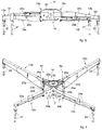
- the front and back stabilizing legs 12a, 12b, 13a and 13b are supported by a support structure 18, provided with at least one pair of box-like elements 19a and 19b which cross in a crossing zone Z.
- each box-like element 19a, 19b has an oblong development and is disposed transverse to and overlapping the other box-like element 19b, 19a, to define a cross shape.
- Each box-like element 19a, 19b is provided with a respective tubular cavity in which a respective front stabilizing leg 12a, 12b can be inserted slidingly, as described below.
- the box-like elements 19a, 19b can be defined by section bars having a polygonal cross-section, preferably rectangular.
- the front stabilizing legs 12a, 12b can have a cross-section shape substantially identical to that of the box-like elements 19a, 19b to allow their reciprocal sliding coupling.
- each tubular cavity is at least open in correspondence with one of its first ends to allow the insertion and sliding of the respective front stabilizing leg 12a, 12b.
- the support structure 18 is provided, in the crossing zone Z of the box-like elements 19a and 19b, with a housing seating 20 to house the movement turret 14.
- the housing seating 20 defines a guide for the rotation of the movement turret 14 around the axis of rotation V.
- the support structure 18 is formed by a single block, for example made of sheet metal or suchlike, suitable to define the box-like elements 19a and 19b and the housing seating 20 of the movement turret 14.
- the support structure 18 can therefore be substantially cross-shaped, at the center of which the housing seating 20 of the movement turret 14 is positioned.
- the housing seating 20 of the movement turret 14 can have a cylindrical shape and is able to house at least a corresponding cylindrical part of the movement turret 14.
- the housing seating 20 of the movement turret 14 is positioned above the crossing zone Z of the box-like elements 19a and 19b.
- This positioning of the movement turret 14 allows to directly discharge the loads acting on the latter toward the box-like elements 19a, 19b, preventing deviations of the stress loading paths as occurs, for example, in known solutions.
- the axis of rotation V of the movement turret 14 is disposed at the center of the seating 20, hence substantially at the center of the movement turret 14.
- the front stabilizing legs 12a and 12b can be selectively inserted/extracted, by means of telescopic sliding, into/from the tubular cavity of the box-like element 19a, 19b to respectively assume an inactive position, retracted inside the tubular cavity, and an active position extended outside the tubular cavity, in which the operating machine is stabilized.
- each tubular cavity of the box-like elements 19a, 19b defines a respective sliding axis S1 and S2 along which the front stabilizing legs 12a, 12b are slidingly moved.
- the front stabilizing legs 12a and 12b comprise extending telescopic elements 24a and 24b which, in the retracted position, are housed in a corresponding box-like element 19a and 19b of the support structure 18.
- Each box-like element 19a and 19b comprises a first end 23a and 23b which is open and is able to allow the front stabilizing legs 12a, 12b to enter and exit, that is, in this case the extending telescopic elements 24a and 24b of the front stabilizer legs 12a and 12b.
- the telescopic elements 24a and 24b of the front stabilizing legs 12a and 12b can be extended in the operating position by means of corresponding actuators 26a and 26b ( fig. 6 ).
- the telescopic elements 24a and 24b of the front stabilizing legs 12a and 12b are extendable or retractable along the sliding axes S1 and S2 which both pass through the crossing zone Z of the support structure 18.
- the sliding axes S1 and S2, therefore ultimately also the box-like elements 19a and 19b, are offset in height so that the front stabilizing legs 12a and 12b, that is, their telescopic elements 24a, 24b, do not interfere with each other and therefore have the necessary space for sliding inside the corresponding box-shaped elements 19a and 19b of the support structure 18.
- Each box-like element 19a and 19b of the support structure 18 comprises a second end 25a and 25b, opposite the first end 23a and 23b, on which the back stabilizing legs 13a and 13b are pivoted, which therefore can rotate with respect to corresponding axes of rotation R1 and R2 from an inactive closed position to an open operating position, or vice versa.
- the back stabilizing legs 13a and 13b can be connected to the support structure 18 and in particular to the second end 25a and 25b of the box-like elements 19a and 19b by means of a rotation pin 27a and 27b defining an axis of rotation R1 and R2, for rotation of the back stabilizing legs 13a, 13b, see figs. 4 or 5 for example.
- the back stabilizing legs 13a and 13b can pass from the closed inactive position to the open operating position by rotation around the axes of rotation R1 and R2.
- Corresponding actuators 28a and 28b can be connected to the back stabilizing legs 13a, 13b and to the support structure 18, to take the back stabilizing legs 13a, 13b from the inactive position to the active position, or vice versa.
- any one of the two sliding axes S1 and S2 of the telescopic elements 24a or 24b of the front stabilizing legs 12a or 12b is aligned with the axis of rotation R1 or R2 of the corresponding back stabilizing leg 13a or 13b.
- the housing seating 20 for the movement turret 14 is made in the crossing zone Z in which the sliding axes S1 and S2 and thus the box-like elements 19a and 19b converge.
- first end 23a, 23b and the second end 25a, 25b of each box-like element 19a, 19b are aligned with each other along the respective sliding axis S1, S2.
- each sliding axis S1, S2 intersects the axis of rotation V of the movement turret 14.
- each sliding axis S1, S2 of one of the front stabilizing legs 12a, 12b intersects one of the axes of rotation R1, R2 of one of the back stabilizing legs 13a, 13b, see the plan view in fig. 5 .
- this reciprocal disposition of the sliding axes S 1 and S2 and of the axis of rotation V allows to distribute the mechanical loads induced by the movement turret 14 toward the front and back stabilizing legs in a uniform manner.
- the mechanical loads can be discharged from the center of the housing seating 20 toward the first ends 23a, 23b and toward the second ends 25a, 25b along a substantially radial path, with respect to the center of the housing seating 20. This prevents excessive deviations of the loads that can cause extremely high intensification of the stresses in correspondence with specific components, with consequent damage thereto.
- the opposite ends 23a and 23b and 25a and 25b of the box-like elements 19a and 19b can be disposed close together or in proximity to the housing seating 20 of the movement turret 14.
- the housing seating 20 has a substantially cylindrical conformation and that the opposite ends 23a, 23b, 25a, and 25b are located on the periphery and tangent to the housing seating 20.
- This disposition allows to further increase the compactness of the support structure 18 and further improve the distribution of loads, consequent to the use of the front and back stabilizing legs 12a and 12b and 13a and 13b.
- the distance between any one of the axes of rotation R1 or R2 of the back stabilizing legs 13a or 13b and the axis of rotation V of the movement turret 14 can also be substantially equal to the distance between the axis of rotation V and any one of the open ends 23a or 23b of the box-like elements 19a or 19b.
- the axis of rotation V of the movement turret 14 can be substantially perpendicular to the sliding axes S1 and S2 of the telescopic elements 24a and 24b.
- the axis of rotation V of the movement turret 14 can also be parallel to the axes of rotation R1 and R2 of the back stabilizing legs 13a and 13b.
- the mobile operating machine 10 will naturally be equipped with service systems 29, for example an oil tank or other.
- the service systems 29 can be positioned outside the support structure 18, as shown schematically in fig. 5 .
- the box-like elements 19a, 19b define between them a concavity 30 comprised between the second ends 25a, 25b of the box-like elements 19a, 19b, and in which the service systems 29 can be installed in a selectively removable manner.
- the support structure 18 can be provided with connection and support brackets 31, installed in the concavity 30 and configured to allow to connect and support the service systems 29.
- This solution allows to greatly simplify the step of allocating spaces with regard to service systems 29, and in particular an oil tank.
- the oil tank unlike in known solutions, can be separate and independent from the support structure 18, which therefore has only a structural function.
Landscapes
- Engineering & Computer Science (AREA)
- Mechanical Engineering (AREA)
- Forklifts And Lifting Vehicles (AREA)
- Eye Examination Apparatus (AREA)
- Lifting Devices For Agricultural Implements (AREA)
- Transplanting Machines (AREA)
Claims (8)
- Fahrbare Betriebsmaschine, versehen mit zumindest einer Arbeitsvorrichtung (11), die von einem Bewegungsrevolverkopf (14) gestützt ist, zumindest einem Paar von stabilisierenden vorderen Beinen (12a, 12b) und zumindest einem Paar von stabilisierenden hinteren Beinen (13a, 13b), worin die fahrbare Betriebsmaschine eine Stützstruktur (18), die mit zumindest einem Paar von kastenartigen Elementen (19a, 19b) versehen ist, die dafür ausgelegt sind, die stabilisierenden vorderen Beinen (12a, 12b) oder hinteren Beinen unterzubringen, und zumindest einen Positionierungssitz (20) des Bewegungsrevolverkopfes (14), der in einem Kreuzungsbereich (Z) der kastenartigen Elemente (19a, 19b) ausgestaltet ist, umfasst, wobei jedes kastenartige Element (19a, 19b) mit einem ersten Ende (23a, 23b), das offen ist und durch welches ein jeweiliges stabilisierendes vorderes Bein (12a, 12b), oder hinteres Bein, gleitend beweglich ist, und mit einem zweiten Ende (25a, 25b), das dem ersten Ende (23a, 23b) entgegengesetzt ist und an dem ein jeweiliges stabilisierendes hinteres Bein (13a, 13b), oder vorderes Bein, geschwenkt wird, so dass es sich um eine entsprechende Drehachse (R1, R2) dreht, versehen ist, worin jedes kastenartige Element (19a, 19b) mit einem jeweiligen rohrförmigen Hohlraum versehen ist, der eine jeweilige Gleitachse (S1, S2) definiert, entlang welcher eines der stabilisierenden vorderen Beine (12a, 12b) gleitend bewegt wird, worin jede Gleitachse (S1, S2) der stabilisierenden vorderen Beine (12a, 12b) eine Drehachse (V) des Bewegungsrevolverkopfes (14) schneidet, worin jede Gleitachse (S1, S2) eines der stabilisierenden vorderen Beine (12a, 12b) eine der Drehachsen (R1, R2) der stabilisierenden hinteren Beine (13a, 13b) schneidet, und dadurch gekennzeichnet, dass die Gleitachsen (S1, S2) in Höhe versetzt sind.
- Fahrbare Betriebsmaschine nach Anspruch 1, dadurch gekennzeichnet, dass die Stützstruktur (18) von einem einzelnen Block gebildet ist, der dafür geeignet ist, die kastenartigen Elemente (19a, 19b) und den Positionierungssitz (20) des Bewegungsrevolverkopfes (14) zu definieren.
- Fahrbare Betriebsmaschine nach Anspruch 1 oder 2, dadurch gekennzeichnet, dass der Positionierungssitz (20) des Bewegungsrevolverkopfes (14) über der kastenartigen Elemente (19a, 19b) ausgestaltet ist und eine Drehachse (V) des Bewegungsrevolverkopfes (14) ihn durchläuft.
- Fahrbare Betriebsmaschine nach Anspruch 3, dadurch gekennzeichnet, dass die Drehachse (V) des Bewegungsrevolverkopfes (14) im Wesentlichen zu den Drehachsen (R1, R2) parallel ist, um welche sich die stabilisierenden hinteren Beine (13a, 13b) drehen.
- Fahrbare Betriebsmaschine nach einem der vorhergehenden Ansprüche, dadurch gekennzeichnet, dass das erste Ende (23a, 23b) und das zweite Ende (25a, 25b) jedes kastenartigen Elementes (19a, 19b) entlang der jeweiligen Gleitachsen (S1, S2) eines der stabilisierenden vorderen Beine (12a, 12b) zueinander ausgerichtet sind.
- Fahrbare Betriebsmaschine nach einem der Ansprüche 3 bis 5, dadurch gekennzeichnet, dass die Drehachse (V) des Bewegungsrevolverkopfes (14) im Wesentlichen senkrecht zu den Gleitachsen (S1, S2) ist.
- Fahrbare Betriebsmaschine nach einem der vorhergehenden Ansprüche, dadurch gekennzeichnet, dass die Stützstruktur (18) im Wesentlichen kreuzförmig ist, wobei in deren Mitte der Unterbringungssitz (20) des Bewegungsrevolverkopfes (14) positioniert ist.
- Fahrbare Betriebsmaschine nach einem der vorhergehenden Ansprüche, dadurch gekennzeichnet, dass die stabilisierenden vorderen Beine (12a, 12b), oder hinteren Beine, die in den kastenartigen Elementen (19a, 19b) gleiten, teleskopische Verlängerungselemente (24a, 24b) entlang der Gleitachsen (S1, S2) umfassen.
Applications Claiming Priority (1)
| Application Number | Priority Date | Filing Date | Title |
|---|---|---|---|
| IT201800001069A IT201800001069A1 (it) | 2018-01-16 | 2018-01-16 | Macchina operatrice mobile |
Publications (2)
| Publication Number | Publication Date |
|---|---|
| EP3511285A1 EP3511285A1 (de) | 2019-07-17 |
| EP3511285B1 true EP3511285B1 (de) | 2020-10-21 |
Family
ID=61952895
Family Applications (1)
| Application Number | Title | Priority Date | Filing Date |
|---|---|---|---|
| EP19151993.3A Active EP3511285B1 (de) | 2018-01-16 | 2019-01-15 | Mobielbetriebsmaschine |
Country Status (3)
| Country | Link |
|---|---|
| US (1) | US10611345B2 (de) |
| EP (1) | EP3511285B1 (de) |
| IT (1) | IT201800001069A1 (de) |
Families Citing this family (5)
| Publication number | Priority date | Publication date | Assignee | Title |
|---|---|---|---|---|
| IT201800001069A1 (it) * | 2018-01-16 | 2019-07-16 | Cifa Spa | Macchina operatrice mobile |
| CN215672920U (zh) * | 2021-08-31 | 2022-01-28 | 三一汽车制造有限公司 | 固定转塔及作业机械 |
| IT202100024436A1 (it) * | 2021-09-23 | 2023-03-23 | Cifa Spa | Macchina operatrice mobile ibrida e suo procedimento di funzionamento |
| US11753253B1 (en) * | 2022-12-28 | 2023-09-12 | Walter Bynum | Feeder assembly for delivering material to a main boom assembly |
| CN119706647B (zh) * | 2025-02-27 | 2025-05-13 | 山西路桥智慧交通信息科技有限公司 | 一种用于高速公路建设的抗倾覆起重机 |
Family Cites Families (22)
| Publication number | Priority date | Publication date | Assignee | Title |
|---|---|---|---|---|
| US4624357A (en) * | 1984-06-25 | 1986-11-25 | Rotec Industries, Inc. | Vehicle-mounted extensible conveyor |
| US5758785A (en) * | 1995-06-22 | 1998-06-02 | Spinosa; Dominic | Lifting system |
| DE19736108A1 (de) * | 1997-08-21 | 1999-02-25 | Putzmeister Ag | Fahrbare Arbeitsmaschine mit teleskopierbaren Stützauslegern |
| DE10032622A1 (de) * | 2000-07-07 | 2002-01-17 | Putzmeister Ag | Stützausleger für fahrbare Arbeitsmaschinen und Autobetonpumpen mit solchen Stützauslegern |
| US6811161B1 (en) * | 2001-08-23 | 2004-11-02 | Sutphen Corporation | Fire engine having extension ladder and lateral stabilizers |
| DE102005007522A1 (de) * | 2005-02-17 | 2006-08-31 | Putzmeister Ag | Stützausleger für fahrbare Arbeitsmaschinen |
| ITMI20060774A1 (it) * | 2006-04-19 | 2007-10-20 | Cifa Spa | Pompa per calcestruzzo mobile provvista di un complesso di stabilizzazione perfezionato |
| DE102006031257A1 (de) * | 2006-07-06 | 2008-01-10 | Putzmeister Ag | Autobetonpumpe mit Knickmast |
| CN101204950A (zh) * | 2006-12-22 | 2008-06-25 | 三一重工股份有限公司 | 行走式机械中使用的可伸缩支承装置 |
| DE102007008881A1 (de) * | 2007-02-21 | 2008-08-28 | Putzmeister Concrete Pumps Gmbh | Verfahren zum Aufstellen einer mobilen Arbeitsmaschine |
| DE102008007917A1 (de) * | 2008-02-06 | 2009-08-13 | Putzmeister Concrete Pumps Gmbh | Fahrbare Arbeitsmaschine |
| DE102008007918A1 (de) * | 2008-02-06 | 2009-08-13 | Putzmeister Concrete Pumps Gmbh | Fahrbare Arbeitsmaschine |
| DE102008055625A1 (de) * | 2008-11-03 | 2010-05-06 | Putzmeister Concrete Pumps Gmbh | Fahrbare Arbeitsmaschine mit Stützauslegern |
| DE102010043957A1 (de) * | 2010-11-16 | 2012-05-16 | Putzmeister Engineering Gmbh | Mobiles Arbeitsgerät mit Abstützkonstruktion |
| CN102364010B (zh) * | 2011-11-18 | 2013-08-28 | 三一汽车制造有限公司 | 一种轮式布料机械 |
| CN103158682A (zh) * | 2011-12-14 | 2013-06-19 | 徐工集团工程机械股份有限公司 | 一种具有x支腿的混凝土泵车底架结构及混凝土泵车 |
| DE102012215049A1 (de) * | 2012-08-24 | 2014-03-20 | Putzmeister Engineering Gmbh | Fahrbare Betonpumpe |
| DE102012215050A1 (de) * | 2012-08-24 | 2014-03-27 | Putzmeister Engineering Gmbh | Fahrbare Betonpumpe |
| DE102013206366A1 (de) * | 2013-04-11 | 2014-10-16 | Putzmeister Engineering Gmbh | Fahrbare Betonpumpe mit Verteilermast und Abstützvorrichtung |
| DE102013209878A1 (de) * | 2013-05-28 | 2014-12-04 | Putzmeister Engineering Gmbh | Arbeitsgerät mit an einem Drehkopf angeordneten Arbeitsausleger |
| WO2015198089A1 (en) * | 2014-06-23 | 2015-12-30 | Socage S.R.L. | Support frame |
| IT201800001069A1 (it) * | 2018-01-16 | 2019-07-16 | Cifa Spa | Macchina operatrice mobile |
-
2018
- 2018-01-16 IT IT201800001069A patent/IT201800001069A1/it unknown
-
2019
- 2019-01-15 EP EP19151993.3A patent/EP3511285B1/de active Active
- 2019-01-15 US US16/248,181 patent/US10611345B2/en not_active Expired - Fee Related
Non-Patent Citations (1)
| Title |
|---|
| None * |
Also Published As
| Publication number | Publication date |
|---|---|
| EP3511285A1 (de) | 2019-07-17 |
| US10611345B2 (en) | 2020-04-07 |
| IT201800001069A1 (it) | 2019-07-16 |
| US20190217826A1 (en) | 2019-07-18 |
Similar Documents
| Publication | Publication Date | Title |
|---|---|---|
| EP3511285B1 (de) | Mobielbetriebsmaschine | |
| EP1916220B1 (de) | Mobiler Hubkran mit variabel positionierbarem Gegengewicht | |
| US5125788A (en) | Quick-change system | |
| CN107227748B (zh) | 挡土用l型钢合成内支撑结构物 | |
| US10717633B2 (en) | Adjustable length tensioning member | |
| US8348073B2 (en) | Carbody connection system and crane using same | |
| US7997432B2 (en) | Trunnion transportation system and crane using same | |
| US9279230B2 (en) | Implement with a boom | |
| US5140929A (en) | Handling boom comprising a main boom and an additional boom | |
| CN111542702A (zh) | 用于抑制具有液压控制的吊杆或细长构件的机器中的质量感应振动的系统 | |
| US10005646B2 (en) | Boom element, telescopic boom, pinning system and construction vehicle | |
| EP1861330B1 (de) | Stabilisierungsvorrichtung für ein schweres arbeitsfahrzeug | |
| CN214462660U (zh) | 固定转塔及设有该固定转塔的作业机械 | |
| US3547278A (en) | Mobile cranes | |
| CA2630509C (en) | Articulated mast for a thick-matter delivery installation | |
| CN102556011A (zh) | 支腿结构及具有该支腿结构的工程机械 | |
| KR200377476Y1 (ko) | 고소작업차량의 아웃트리거 | |
| CN114538293A (zh) | 塔式起重机 | |
| JP2022164335A (ja) | 建設機械 | |
| JP6959055B2 (ja) | 主柱材交換方法 | |
| US9975741B2 (en) | Mobile work machine having an outrigger and an extension for widening the support base | |
| KR102407194B1 (ko) | 중장비용 아우트리거 프레임 구조 | |
| AU2006328493A1 (en) | Stabilizer device for a heavy work vehicle | |
| ITMI20040413U1 (it) | Dispositivo per ruotare un'unita' di stabilizzazioone per mezzi mobili, azionata oleodinamicamente |
Legal Events
| Date | Code | Title | Description |
|---|---|---|---|
| PUAI | Public reference made under article 153(3) epc to a published international application that has entered the european phase |
Free format text: ORIGINAL CODE: 0009012 |
|
| STAA | Information on the status of an ep patent application or granted ep patent |
Free format text: STATUS: THE APPLICATION HAS BEEN PUBLISHED |
|
| AK | Designated contracting states |
Kind code of ref document: A1 Designated state(s): AL AT BE BG CH CY CZ DE DK EE ES FI FR GB GR HR HU IE IS IT LI LT LU LV MC MK MT NL NO PL PT RO RS SE SI SK SM TR |
|
| AX | Request for extension of the european patent |
Extension state: BA ME |
|
| STAA | Information on the status of an ep patent application or granted ep patent |
Free format text: STATUS: REQUEST FOR EXAMINATION WAS MADE |
|
| 17P | Request for examination filed |
Effective date: 20200114 |
|
| RBV | Designated contracting states (corrected) |
Designated state(s): AL AT BE BG CH CY CZ DE DK EE ES FI FR GB GR HR HU IE IS IT LI LT LU LV MC MK MT NL NO PL PT RO RS SE SI SK SM TR |
|
| GRAP | Despatch of communication of intention to grant a patent |
Free format text: ORIGINAL CODE: EPIDOSNIGR1 |
|
| STAA | Information on the status of an ep patent application or granted ep patent |
Free format text: STATUS: GRANT OF PATENT IS INTENDED |
|
| INTG | Intention to grant announced |
Effective date: 20200617 |
|
| GRAS | Grant fee paid |
Free format text: ORIGINAL CODE: EPIDOSNIGR3 |
|
| GRAA | (expected) grant |
Free format text: ORIGINAL CODE: 0009210 |
|
| STAA | Information on the status of an ep patent application or granted ep patent |
Free format text: STATUS: THE PATENT HAS BEEN GRANTED |
|
| AK | Designated contracting states |
Kind code of ref document: B1 Designated state(s): AL AT BE BG CH CY CZ DE DK EE ES FI FR GB GR HR HU IE IS IT LI LT LU LV MC MK MT NL NO PL PT RO RS SE SI SK SM TR |
|
| REG | Reference to a national code |
Ref country code: GB Ref legal event code: FG4D |
|
| REG | Reference to a national code |
Ref country code: CH Ref legal event code: EP |
|
| REG | Reference to a national code |
Ref country code: IE Ref legal event code: FG4D |
|
| REG | Reference to a national code |
Ref country code: DE Ref legal event code: R096 Ref document number: 602019000968 Country of ref document: DE |
|
| REG | Reference to a national code |
Ref country code: AT Ref legal event code: REF Ref document number: 1325662 Country of ref document: AT Kind code of ref document: T Effective date: 20201115 |
|
| REG | Reference to a national code |
Ref country code: NL Ref legal event code: MP Effective date: 20201021 |
|
| PG25 | Lapsed in a contracting state [announced via postgrant information from national office to epo] |
Ref country code: FI Free format text: LAPSE BECAUSE OF FAILURE TO SUBMIT A TRANSLATION OF THE DESCRIPTION OR TO PAY THE FEE WITHIN THE PRESCRIBED TIME-LIMIT Effective date: 20201021 Ref country code: PT Free format text: LAPSE BECAUSE OF FAILURE TO SUBMIT A TRANSLATION OF THE DESCRIPTION OR TO PAY THE FEE WITHIN THE PRESCRIBED TIME-LIMIT Effective date: 20210222 Ref country code: RS Free format text: LAPSE BECAUSE OF FAILURE TO SUBMIT A TRANSLATION OF THE DESCRIPTION OR TO PAY THE FEE WITHIN THE PRESCRIBED TIME-LIMIT Effective date: 20201021 Ref country code: NO Free format text: LAPSE BECAUSE OF FAILURE TO SUBMIT A TRANSLATION OF THE DESCRIPTION OR TO PAY THE FEE WITHIN THE PRESCRIBED TIME-LIMIT Effective date: 20210121 Ref country code: GR Free format text: LAPSE BECAUSE OF FAILURE TO SUBMIT A TRANSLATION OF THE DESCRIPTION OR TO PAY THE FEE WITHIN THE PRESCRIBED TIME-LIMIT Effective date: 20210122 |
|
| REG | Reference to a national code |
Ref country code: LT Ref legal event code: MG4D |
|
| PG25 | Lapsed in a contracting state [announced via postgrant information from national office to epo] |
Ref country code: ES Free format text: LAPSE BECAUSE OF FAILURE TO SUBMIT A TRANSLATION OF THE DESCRIPTION OR TO PAY THE FEE WITHIN THE PRESCRIBED TIME-LIMIT Effective date: 20201021 Ref country code: LV Free format text: LAPSE BECAUSE OF FAILURE TO SUBMIT A TRANSLATION OF THE DESCRIPTION OR TO PAY THE FEE WITHIN THE PRESCRIBED TIME-LIMIT Effective date: 20201021 Ref country code: IS Free format text: LAPSE BECAUSE OF FAILURE TO SUBMIT A TRANSLATION OF THE DESCRIPTION OR TO PAY THE FEE WITHIN THE PRESCRIBED TIME-LIMIT Effective date: 20210221 Ref country code: PL Free format text: LAPSE BECAUSE OF FAILURE TO SUBMIT A TRANSLATION OF THE DESCRIPTION OR TO PAY THE FEE WITHIN THE PRESCRIBED TIME-LIMIT Effective date: 20201021 Ref country code: SE Free format text: LAPSE BECAUSE OF FAILURE TO SUBMIT A TRANSLATION OF THE DESCRIPTION OR TO PAY THE FEE WITHIN THE PRESCRIBED TIME-LIMIT Effective date: 20201021 Ref country code: BG Free format text: LAPSE BECAUSE OF FAILURE TO SUBMIT A TRANSLATION OF THE DESCRIPTION OR TO PAY THE FEE WITHIN THE PRESCRIBED TIME-LIMIT Effective date: 20210121 |
|
| PG25 | Lapsed in a contracting state [announced via postgrant information from national office to epo] |
Ref country code: NL Free format text: LAPSE BECAUSE OF FAILURE TO SUBMIT A TRANSLATION OF THE DESCRIPTION OR TO PAY THE FEE WITHIN THE PRESCRIBED TIME-LIMIT Effective date: 20201021 Ref country code: HR Free format text: LAPSE BECAUSE OF FAILURE TO SUBMIT A TRANSLATION OF THE DESCRIPTION OR TO PAY THE FEE WITHIN THE PRESCRIBED TIME-LIMIT Effective date: 20201021 |
|
| REG | Reference to a national code |
Ref country code: DE Ref legal event code: R097 Ref document number: 602019000968 Country of ref document: DE |
|
| PG25 | Lapsed in a contracting state [announced via postgrant information from national office to epo] |
Ref country code: SM Free format text: LAPSE BECAUSE OF FAILURE TO SUBMIT A TRANSLATION OF THE DESCRIPTION OR TO PAY THE FEE WITHIN THE PRESCRIBED TIME-LIMIT Effective date: 20201021 Ref country code: SK Free format text: LAPSE BECAUSE OF FAILURE TO SUBMIT A TRANSLATION OF THE DESCRIPTION OR TO PAY THE FEE WITHIN THE PRESCRIBED TIME-LIMIT Effective date: 20201021 Ref country code: EE Free format text: LAPSE BECAUSE OF FAILURE TO SUBMIT A TRANSLATION OF THE DESCRIPTION OR TO PAY THE FEE WITHIN THE PRESCRIBED TIME-LIMIT Effective date: 20201021 Ref country code: CZ Free format text: LAPSE BECAUSE OF FAILURE TO SUBMIT A TRANSLATION OF THE DESCRIPTION OR TO PAY THE FEE WITHIN THE PRESCRIBED TIME-LIMIT Effective date: 20201021 Ref country code: RO Free format text: LAPSE BECAUSE OF FAILURE TO SUBMIT A TRANSLATION OF THE DESCRIPTION OR TO PAY THE FEE WITHIN THE PRESCRIBED TIME-LIMIT Effective date: 20201021 Ref country code: LT Free format text: LAPSE BECAUSE OF FAILURE TO SUBMIT A TRANSLATION OF THE DESCRIPTION OR TO PAY THE FEE WITHIN THE PRESCRIBED TIME-LIMIT Effective date: 20201021 |
|
| PLBE | No opposition filed within time limit |
Free format text: ORIGINAL CODE: 0009261 |
|
| STAA | Information on the status of an ep patent application or granted ep patent |
Free format text: STATUS: NO OPPOSITION FILED WITHIN TIME LIMIT |
|
| PG25 | Lapsed in a contracting state [announced via postgrant information from national office to epo] |
Ref country code: DK Free format text: LAPSE BECAUSE OF FAILURE TO SUBMIT A TRANSLATION OF THE DESCRIPTION OR TO PAY THE FEE WITHIN THE PRESCRIBED TIME-LIMIT Effective date: 20201021 Ref country code: MC Free format text: LAPSE BECAUSE OF FAILURE TO SUBMIT A TRANSLATION OF THE DESCRIPTION OR TO PAY THE FEE WITHIN THE PRESCRIBED TIME-LIMIT Effective date: 20201021 |
|
| 26N | No opposition filed |
Effective date: 20210722 |
|
| PG25 | Lapsed in a contracting state [announced via postgrant information from national office to epo] |
Ref country code: LU Free format text: LAPSE BECAUSE OF NON-PAYMENT OF DUE FEES Effective date: 20210115 |
|
| REG | Reference to a national code |
Ref country code: BE Ref legal event code: MM Effective date: 20210131 |
|
| PG25 | Lapsed in a contracting state [announced via postgrant information from national office to epo] |
Ref country code: AL Free format text: LAPSE BECAUSE OF FAILURE TO SUBMIT A TRANSLATION OF THE DESCRIPTION OR TO PAY THE FEE WITHIN THE PRESCRIBED TIME-LIMIT Effective date: 20201021 |
|
| PG25 | Lapsed in a contracting state [announced via postgrant information from national office to epo] |
Ref country code: SI Free format text: LAPSE BECAUSE OF FAILURE TO SUBMIT A TRANSLATION OF THE DESCRIPTION OR TO PAY THE FEE WITHIN THE PRESCRIBED TIME-LIMIT Effective date: 20201021 |
|
| PG25 | Lapsed in a contracting state [announced via postgrant information from national office to epo] |
Ref country code: IE Free format text: LAPSE BECAUSE OF NON-PAYMENT OF DUE FEES Effective date: 20210115 |
|
| PG25 | Lapsed in a contracting state [announced via postgrant information from national office to epo] |
Ref country code: IS Free format text: LAPSE BECAUSE OF FAILURE TO SUBMIT A TRANSLATION OF THE DESCRIPTION OR TO PAY THE FEE WITHIN THE PRESCRIBED TIME-LIMIT Effective date: 20210221 |
|
| PG25 | Lapsed in a contracting state [announced via postgrant information from national office to epo] |
Ref country code: BE Free format text: LAPSE BECAUSE OF NON-PAYMENT OF DUE FEES Effective date: 20210131 |
|
| REG | Reference to a national code |
Ref country code: AT Ref legal event code: UEP Ref document number: 1325662 Country of ref document: AT Kind code of ref document: T Effective date: 20201021 |
|
| P01 | Opt-out of the competence of the unified patent court (upc) registered |
Effective date: 20230521 |
|
| PG25 | Lapsed in a contracting state [announced via postgrant information from national office to epo] |
Ref country code: CY Free format text: LAPSE BECAUSE OF FAILURE TO SUBMIT A TRANSLATION OF THE DESCRIPTION OR TO PAY THE FEE WITHIN THE PRESCRIBED TIME-LIMIT Effective date: 20201021 |
|
| PG25 | Lapsed in a contracting state [announced via postgrant information from national office to epo] |
Ref country code: HU Free format text: LAPSE BECAUSE OF FAILURE TO SUBMIT A TRANSLATION OF THE DESCRIPTION OR TO PAY THE FEE WITHIN THE PRESCRIBED TIME-LIMIT; INVALID AB INITIO Effective date: 20190115 |
|
| PG25 | Lapsed in a contracting state [announced via postgrant information from national office to epo] |
Ref country code: MK Free format text: LAPSE BECAUSE OF FAILURE TO SUBMIT A TRANSLATION OF THE DESCRIPTION OR TO PAY THE FEE WITHIN THE PRESCRIBED TIME-LIMIT Effective date: 20201021 |
|
| PGFP | Annual fee paid to national office [announced via postgrant information from national office to epo] |
Ref country code: GB Payment date: 20240111 Year of fee payment: 6 |
|
| PGFP | Annual fee paid to national office [announced via postgrant information from national office to epo] |
Ref country code: FR Payment date: 20240119 Year of fee payment: 6 |
|
| PG25 | Lapsed in a contracting state [announced via postgrant information from national office to epo] |
Ref country code: TR Free format text: LAPSE BECAUSE OF FAILURE TO SUBMIT A TRANSLATION OF THE DESCRIPTION OR TO PAY THE FEE WITHIN THE PRESCRIBED TIME-LIMIT Effective date: 20201021 |
|
| PG25 | Lapsed in a contracting state [announced via postgrant information from national office to epo] |
Ref country code: MT Free format text: LAPSE BECAUSE OF FAILURE TO SUBMIT A TRANSLATION OF THE DESCRIPTION OR TO PAY THE FEE WITHIN THE PRESCRIBED TIME-LIMIT Effective date: 20201021 |
|
| GBPC | Gb: european patent ceased through non-payment of renewal fee |
Effective date: 20250115 |
|
| PG25 | Lapsed in a contracting state [announced via postgrant information from national office to epo] |
Ref country code: GB Free format text: LAPSE BECAUSE OF NON-PAYMENT OF DUE FEES Effective date: 20250115 |
|
| PG25 | Lapsed in a contracting state [announced via postgrant information from national office to epo] |
Ref country code: FR Free format text: LAPSE BECAUSE OF NON-PAYMENT OF DUE FEES Effective date: 20250131 |
|
| REG | Reference to a national code |
Ref country code: CH Ref legal event code: U11 Free format text: ST27 STATUS EVENT CODE: U-0-0-U10-U11 (AS PROVIDED BY THE NATIONAL OFFICE) Effective date: 20260201 |
|
| PGFP | Annual fee paid to national office [announced via postgrant information from national office to epo] |
Ref country code: DE Payment date: 20260127 Year of fee payment: 8 |
|
| PGFP | Annual fee paid to national office [announced via postgrant information from national office to epo] |
Ref country code: AT Payment date: 20260119 Year of fee payment: 8 |
|
| PGFP | Annual fee paid to national office [announced via postgrant information from national office to epo] |
Ref country code: IT Payment date: 20260121 Year of fee payment: 8 |
|
| PGFP | Annual fee paid to national office [announced via postgrant information from national office to epo] |
Ref country code: CH Payment date: 20260201 Year of fee payment: 8 |