EP3511270A1 - Steigschnecke - Google Patents
Steigschnecke Download PDFInfo
- Publication number
- EP3511270A1 EP3511270A1 EP19150967.8A EP19150967A EP3511270A1 EP 3511270 A1 EP3511270 A1 EP 3511270A1 EP 19150967 A EP19150967 A EP 19150967A EP 3511270 A1 EP3511270 A1 EP 3511270A1
- Authority
- EP
- European Patent Office
- Prior art keywords
- screw
- conveying
- blade
- conveying direction
- conveyor
- Prior art date
- Legal status (The legal status is an assumption and is not a legal conclusion. Google has not performed a legal analysis and makes no representation as to the accuracy of the status listed.)
- Granted
Links
Images

Classifications
-
- B—PERFORMING OPERATIONS; TRANSPORTING
- B65—CONVEYING; PACKING; STORING; HANDLING THIN OR FILAMENTARY MATERIAL
- B65G—TRANSPORT OR STORAGE DEVICES, e.g. CONVEYORS FOR LOADING OR TIPPING, SHOP CONVEYOR SYSTEMS OR PNEUMATIC TUBE CONVEYORS
- B65G33/00—Screw or rotary spiral conveyors
- B65G33/24—Details
- B65G33/26—Screws
- B65G33/265—Screws with a continuous helical surface
-
- B—PERFORMING OPERATIONS; TRANSPORTING
- B65—CONVEYING; PACKING; STORING; HANDLING THIN OR FILAMENTARY MATERIAL
- B65G—TRANSPORT OR STORAGE DEVICES, e.g. CONVEYORS FOR LOADING OR TIPPING, SHOP CONVEYOR SYSTEMS OR PNEUMATIC TUBE CONVEYORS
- B65G33/00—Screw or rotary spiral conveyors
- B65G33/24—Details
- B65G33/26—Screws
-
- B—PERFORMING OPERATIONS; TRANSPORTING
- B65—CONVEYING; PACKING; STORING; HANDLING THIN OR FILAMENTARY MATERIAL
- B65G—TRANSPORT OR STORAGE DEVICES, e.g. CONVEYORS FOR LOADING OR TIPPING, SHOP CONVEYOR SYSTEMS OR PNEUMATIC TUBE CONVEYORS
- B65G33/00—Screw or rotary spiral conveyors
- B65G33/24—Details
- B65G33/26—Screws
- B65G33/30—Screws with a discontinuous helical surface
-
- F—MECHANICAL ENGINEERING; LIGHTING; HEATING; WEAPONS; BLASTING
- F23—COMBUSTION APPARATUS; COMBUSTION PROCESSES
- F23K—FEEDING FUEL TO COMBUSTION APPARATUS
- F23K3/00—Feeding or distributing of lump or pulverulent fuel to combustion apparatus
- F23K3/10—Under-feed arrangements
- F23K3/14—Under-feed arrangements feeding by screw
Definitions
- the invention relates to a climbing auger for the promotion of hack and piece goods for a vertical screw conveyor with a helically circulating around a screw core screw blade.
- the invention is therefore based on the object, a climbing screw of the type described in such a way that in a discontinuous conveying process with varying timing a constant flow of material is made possible.
- the invention solves this problem by the fact that the conveying edge of the screw blade has at least one, falling in the conveying direction retention level.
- the invention is based on the observation that the majority of the dead weight of the hack or piece goods to be conveyed is taken up by the spirally rotating worm blade and the force component along the worm blade, which is decisive for a sliding back of the conveyed material, is relatively small.
- the measures according to the invention can be formed by a retaining step, which rises against the conveying direction, a stop for the conveyed, which compensates for this force component.
- the retention stage may have a significantly lower height than the material lying on the worm blade because, due to the small force component acting along the conveying flank, the frictional forces acting within the material flow are sufficient to slow the originallygutstrom total and prevent it from sliding back.
- the retention level drops in the conveying direction, it does not hinder the transport of conveyed material during operation of the screw conveyor, but rather, when overcoming the retention step, only a short-term increase in height of the conveyed material occurs. Due to the elimination of lead times for a continuous promotion not only energy savings, but it can also be reduced due to the conveyor drive resulting noise. This is particularly advantageous in connection with charging processes of furnaces for domestic heating systems.
- the measures according to the invention allow particularly favorable operating conditions with a vertical conveyance of the hack or piece goods, however, the ascending screw according to the invention can also be advantageously used at different angles of rise of the screw conveyor.
- the screw blade has at least two blade segments, which are each arranged offset in the longitudinal direction of the ascending screw to form the retaining step.
- the height of rise of the screw blade remains constant over the delivery height and is interrupted only by the forming of the retention levels at the transition between two leaf segments.
- the speed can therefore remain constant.
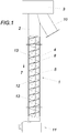
- An ascending screw 1 according to the invention is arranged within a vertical screw conveyor 2 and is driven by a drive 3 shown schematically.
- the ascending screw 1 has a screw core 4 with a helically circulating screw blade 5 around it.
- the screw blade 5 forms in the conveying direction 7 from a conveyor edge 6, which has a sloping in the conveying direction 7 restraint stage 8.
- the ascending screw 1 rotates about its longitudinal axis, so that hack or piece goods 9, such as wood chips, wood pellets or miscanthus, is conveyed in the vertical conveying direction 7 along the screw blade 5 to an ejector 10.
- hack or piece goods 9 such as wood chips, wood pellets or miscanthus
- the drive 3 is not arranged near the bottom, but on the ejector side 10 of the screw conveyor 2, so that a horizontal feed screw conveyor 11 can be placed as close to the ground as possible.
- the auger blade 5 in order to allow a simple production of a riser screw 1 according to the invention, at least two leaf segments 12, 13, which are each arranged offset in the longitudinal direction of the auger 1 to form the retaining stage 8.
- the staggered arrangement can be understood that the preceding in the conveying direction 7 blade segment 12 is set back against the conveying direction 7 in the conveying direction 7 opposite to the conveying direction 7, so that thereby adjusting spacing of the blade segments 12, 13 to each other, the retaining stage 8 is formed.
- Fig. 2 can be removed, a plurality of blade segments 12, 13 arranged offset from one another, the restraint stage 8 according to the invention can be provided without a change in the pitch of the worm blade 5, so that in terms of the drive 3 consistent power ratios.
Landscapes
- Engineering & Computer Science (AREA)
- Mechanical Engineering (AREA)
- Chemical & Material Sciences (AREA)
- Combustion & Propulsion (AREA)
- General Engineering & Computer Science (AREA)
- Screw Conveyors (AREA)
- Devices For Conveying Motion By Means Of Endless Flexible Members (AREA)
- Heterocyclic Compounds That Contain Two Or More Ring Oxygen Atoms (AREA)
Abstract
Description
- Die Erfindung bezieht sich auf eine Steigschnecke zur Förderung von Hack- und Stückgut für einen Vertikalschneckenförderer mit einem um einen Schneckenkern spiralförmig umlaufenden Schneckenblatt.
- Auf dem Gebiet von einen Niveauunterschied überwindenden Stückgutförderern sind Vertikalschneckenförderer bekannt (
DE 1086625 B ), die ein Gehäuse mit um die Längsachse des Förderers rotierende Schnecken zur Förderung von Stückgütern aufweisen. - Werden derartige Schnecken in einem diskontinuierlichen Förderprozess eingesetzt, wie dies beispielsweise bei der Beschickung von Feuerungen für Heizungsanlagen mit stückeligem Brennstoff regelmäßig der Fall ist, wobei die Brennstoffmenge bei konstanter Schneckendrehzahl über einen getakteten Betrieb gesteuert wird, ergibt sich das Problem, dass bei einer Unterbrechung des Förderbetriebes das Hack-oder Stückgut im Schneckenförderer zufolge der Schwerkraft zurückgleitet, sodass bei einem neuerlichen Start des Förderbetriebes Vorlaufzeiten eingerechnet werden müssen, bis das Fördergut wieder am Ausgang des Schneckenförderers zur Verfügung steht.
- Der Erfindung liegt somit die Aufgabe zugrunde, eine Steigschnecke der eingangs geschilderten Art so auszugestalten, dass bei einem diskontinuierlichen Förderprozess mit variierender Taktung ein konstanter Materialfluss ermöglicht wird.
- Die Erfindung löst die gestellte Aufgabe dadurch, dass die Förderflanke des Schneckenblattes wenigstens eine, in Förderrichtung abfallende Rückhaltestufe aufweist.
- Der Erfindung liegt die Beobachtung zugrunde, dass der Großteil des Eigengewichtes des zu fördernden Hack-oder Stückgutes über das spiralförmig umlaufende Schneckenblatt aufgenommen wird und die entlang des umlaufenden Schneckenblattes wirkende, für ein Zurückgleiten des Fördergutes maßgebliche Kraftkomponente verhältnismäßig gering ist. Zufolge der erfindungsgemäßen Maßnahmen kann durch eine Rückhaltestufe, die gegen die Förderrichtung hin ansteigt, ein Anschlag für das Fördergut gebildet werden, der diese Kraftkomponente ausgleicht. Je nach Dimensionierung der Schnecke und dem zu fördernden Hack-oder Stückgut kann dabei die Rückhaltestufe eine deutlich geringere Höhe als das auf dem Schneckenblatt aufliegende Fördergut aufweisen, weil zufolge der geringen, entlang der Förderflanke wirkenden Kraftkomponente, die innerhalb des Fördergutstromes wirkenden Reibungskräfte ausreichen, um den Fördergutstrom insgesamt zu bremsen und an einem Zurückgleiten zu hindern. Dadurch, dass die Rückhaltestufe in Förderrichtung abfällt, behindert sie den Förderguttransport beim Betrieb des Schneckenförderers nicht, sondern es kommt beim Überwinden der Rückhaltestufe lediglich zu einem kurzfristigen Steighöhenverlust für das Fördergut. Zufolge der entfallenden Vorlaufzeiten für eine kontinuierliche Förderung ergeben sich nicht nur Energieeinsparungen, sondern es kann auch die zufolge des Förderantriebes entstehende Lärmentwicklung reduziert werden. Dies ist insbesondere im Zusammenhang mit Beschickungsvorgängen von Feuerungen für häusliche Heizungsanlagen vorteilhaft. Die erfindungsgemäßen Maßnahmen ermöglichen besonders günstige Betriebsbedingungen bei einer vertikalen Förderung des Hack-oder Stückguts, jedoch kann die erfindungsgemäße Steigschnecke auch bei unterschiedlichen Steigwinkeln des Schneckenförderers vorteilhaft eingesetzt werden.
- In Hinblick auf die Rückhaltewirkung und die bei der Förderung auftretenden Steighöhenverluste stellen sich vorteilhafte Bedingungen ein, wenn die Rückhaltestufe eine der Dicke des Schneckenblattes entsprechende Höhe aufweist. Wie bereits oben ausgeführt, reicht eine derartig geringe Höhe der Rückhaltestufe aus, um ein Zurückgleiten des Fördergutstromes wirksam zu verhindern.
- Um nicht nur eine geringe Leistungsaufnahme, sondern auch eine konstruktiv einfache Fertigung einer erfindungsgemäßen Steigschnecke zu ermöglichen wird vorgeschlagen, dass das Schneckenblatt wenigstens zwei Blattsegmente aufweist, die zueinander je in Längsrichtung der Steigschnecke unter Ausbildung der Rückhaltestufe versetzt angeordnet sind. Demzufolge bleibt die Steighöhe des Schneckenblattes über die Förderhöhe konstant und wird lediglich beim Übergang zwischen zwei Blattsegmenten durch die sich ausbildenden Rückhaltestufen unterbrochen. Im Vergleich zu einer Steigschnecke ohne die erfindungsgemäßen Rückhaltestufen kann die Drehzahl daher gleichbleiben.
- In der Zeichnung ist der Erfindungsgegenstand beispielsweise dargestellt. Es zeigen
- Fig. 1
- eine teilweise aufgerissene Seitenansicht eines Vertikalschneckenförderers mit einer erfindungsgemäßen Steigschnecke und
- Fig. 2
- eine perspektivische Detailansicht der Steigschnecke in einem größeren Maßstab.
- Eine erfindungsgemäße Steigschnecke 1 ist innerhalb eines Vertikalschneckenförderers 2 angeordnet und wird von einem schematisch dargestellten Antrieb 3 angetrieben. Dabei weist die Steigschnecke 1 einen Schneckenkern 4 mit einem um diesen spiralförmig umlaufenden Schneckenblatt 5 auf. Das Schneckenblatt 5 bildet in Förderrichtung 7 eine Förderflanke 6 aus, die eine in Förderrichtung 7 abfallende Rückhaltestufe 8 aufweist.
- Im Förderbetrieb rotiert die Steigschnecke 1 um ihre Längsachse, sodass Hack-oder Stückgut 9, wie beispielsweise Hackschnitzel, Holzpellets oder Miscanthus, in vertikaler Förderrichtung 7 entlang des Schneckenblattes 5 zu einem Auswerfer 10 gefördert wird. Besonders günstige Konstruktionsverhältnisse ergeben sich dann, wenn der Antrieb 3 nicht in Bodennähe, sondern auf der Auswerferseite 10 des Schneckenförderers 2 angeordnet ist, sodass ein horizontaler Zubringungsschneckenförderer 11 möglichst in Bodennähe platziert werden kann.
- Bei einer Unterbrechung des Förderbetriebes, das heißt bei Anhalten des Antriebes 3, würde das Hack-oder Stückgut 9 schwerkraftbedingt entlang des Schneckenblattes 5 entgegen der Förderrichtung 7 zurückgleiten, wenn nicht die Rückhaltestufe 8 einen Anschlag für das Hack-oder Stückgut 9 bilden würde. Da das Schneckenblatt 5 bereits einen Großteil der entgegen der Förderrichtung 7 verlaufenden Gewichtskraftkomponenten 7 des Hack-oder Stückgut 9 aufnimmt, verbleibt nur eine geringe entlang des Schneckenblattes 5 wirkende Kraftkomponente, sodass eine Rückhaltestufe 8, deren Höhe in etwa der Dicke des Schneckenblattes 5 entspricht ausreicht, um ein Zurückgleiten des Fördergutstromes 9 insgesamt zu verhindern, weil die inneren Reibungskräfte des Fördergutstromes 9 bereits eine zusätzliche Bremswirkung hervorrufen.
- Um in diesem Zusammenhang eine einfache Fertigung einer erfindungsgemäßen Steigschnecke 1 zu ermöglichen, kann das Schneckenblatt 5 gemäß einer Ausführungsform wenigstens zwei Blattsegmente 12, 13 aufweisen, die zueinander je in Längsrichtung der Steigschnecke 1 unter Ausbildung der Rückhaltestufe 8 versetzt angeordnet sind. Dabei kann die versetzte Anordnung so verstanden werden, dass das in Förderrichtung 7 vorangehende Blattsegment 12 gegenüber dem in Förderrichtung 7 nachfolgenden Blattsegment 13 entgegen der Förderrichtung 7 zurückversetzt ist, sodass die sich dadurch einstellende Beabstandung der Blattsegmente 12, 13 zueinander die Rückhaltestufe 8 ausbildet.
- Werden, wie insbesondere
Fig. 2 entnommen werden kann, mehrere Blattsegmente 12, 13 zueinander versetzt angeordnet, so kann die erfindungsgemäße Rückhaltestufe 8 ohne eine Änderung der Steigung des Schneckenblattes 5 vorgesehen werden, sodass sich hinsichtlich des Antriebes 3 gleichbleibende Leistungsverhältnisse ergeben. - Dadurch, dass zufolge obiger Ausführungen bei einer erfindungsgemäßen Steigschnecke 1 ein Zurückgleiten des zu befördernden Hack-oder Stückgut 9 verhindert werden kann und hierfür auch keine Änderungen des Antriebes 3 daher erforderlich werden, muss dieser in einer typischen Fördersituation, wie sie beispielsweise bei häuslichen Heizungsanlagen anzutreffen ist, deutlich weniger lange in Betrieb gesetzt werden, weil eine Anlaufphase, innerhalb der das Hack-oder Stückgut 9 von der Basis des Vertikalschneckenförderers 2 bis zum Auswerfer 10 gefördert werden muss, entfallen kann.
Claims (3)
- Steigschnecke (1) zur Förderung von Hack- oder Stückgut (9) für einen Vertikalschneckenförderer (2) mit einem um einen Schneckenkern (4) spiralförmig umlaufenden Schneckenblatt (5), dadurch gekennzeichnet, dass die Förderflanke (6) des Schneckenblattes (5) wenigstens eine, in Förderrichtung (7) abfallende Rückhaltestufe (8) aufweist.
- Steigschnecke (1) nach Anspruch 1, dadurch gekennzeichnet, dass die Rückhaltestufe (8) eine der Dicke des Schneckenblattes (5) entsprechende Höhe aufweist.
- Steigschnecke (1) nach Anspruch 1 oder 2, dadurch gekennzeichnet, dass das Schneckenblatt (5) wenigstens zwei Blattsegmente (12), (13) aufweist, die zueinander je in Längsrichtung der Steigschnecke (1) unter Ausbildung der Rückhaltestufe (8) versetzt angeordnet sind.
Applications Claiming Priority (1)
| Application Number | Priority Date | Filing Date | Title |
|---|---|---|---|
| ATA50007/2018A AT520323B1 (de) | 2018-01-10 | 2018-01-10 | Steigschnecke |
Publications (2)
| Publication Number | Publication Date |
|---|---|
| EP3511270A1 true EP3511270A1 (de) | 2019-07-17 |
| EP3511270B1 EP3511270B1 (de) | 2022-12-07 |
Family
ID=65011896
Family Applications (1)
| Application Number | Title | Priority Date | Filing Date |
|---|---|---|---|
| EP19150967.8A Active EP3511270B1 (de) | 2018-01-10 | 2019-01-09 | Steigschnecke |
Country Status (5)
| Country | Link |
|---|---|
| EP (1) | EP3511270B1 (de) |
| AT (1) | AT520323B1 (de) |
| DK (1) | DK3511270T3 (de) |
| ES (1) | ES2937263T3 (de) |
| PL (1) | PL3511270T3 (de) |
Citations (5)
| Publication number | Priority date | Publication date | Assignee | Title |
|---|---|---|---|---|
| US1023888A (en) * | 1910-03-09 | 1912-04-23 | Severin N Sorensen | Smut-machine. |
| US1775888A (en) * | 1924-02-04 | 1930-09-16 | Joseph D Christian | Conveyer flight |
| US3485116A (en) * | 1967-04-24 | 1969-12-23 | Tracy T Fender | Method and apparatus for forming sectional spiral flights |
| US4399906A (en) * | 1981-01-22 | 1983-08-23 | Thomas Conveyor Company, Inc. | Temperature expansive screw conveyor |
| US4860554A (en) * | 1988-09-19 | 1989-08-29 | Innes Robert S | Counter-flow poultry chiller |
Family Cites Families (7)
| Publication number | Priority date | Publication date | Assignee | Title |
|---|---|---|---|---|
| DE841643C (de) * | 1950-05-18 | 1952-06-19 | Werner & Pfleiderer | Schneckenwelle fuer Maschinen zum Kneten und/oder Mischen plastischer Massen, insbesondere Kautschuk- oder Kunststoffmischungen |
| DE1086625B (de) * | 1958-01-07 | 1960-08-04 | Deutsche Bundespost | Vertikaler Schneckenfoerderer fuer Stueckgut |
| DE1142059B (de) * | 1958-04-18 | 1963-01-03 | Hackethal Draht & Kabelwerk Ag | Schneckenpresse zum Verarbeiten, insbesondere zum Strangpressen, thermoplastischer Kunststoffe |
| GB913163A (en) * | 1958-07-30 | 1962-12-19 | Gordon Felber And Company Ltd | Screw conveyors |
| DE1298700B (de) * | 1965-03-18 | 1969-07-03 | Reifenhaeuser Kg | Schneckenpresse |
| NO20063680L (no) * | 2006-08-16 | 2008-02-18 | Rolf Einar Birketvedt | Anordning for pumping av partikulaere materialer |
| WO2017173622A1 (zh) * | 2016-04-07 | 2017-10-12 | 郑朝志 | 一种螺旋轴及其制作方法 |
-
2018
- 2018-01-10 AT ATA50007/2018A patent/AT520323B1/de active
-
2019
- 2019-01-09 EP EP19150967.8A patent/EP3511270B1/de active Active
- 2019-01-09 PL PL19150967.8T patent/PL3511270T3/pl unknown
- 2019-01-09 DK DK19150967.8T patent/DK3511270T3/da active
- 2019-01-09 ES ES19150967T patent/ES2937263T3/es active Active
Patent Citations (5)
| Publication number | Priority date | Publication date | Assignee | Title |
|---|---|---|---|---|
| US1023888A (en) * | 1910-03-09 | 1912-04-23 | Severin N Sorensen | Smut-machine. |
| US1775888A (en) * | 1924-02-04 | 1930-09-16 | Joseph D Christian | Conveyer flight |
| US3485116A (en) * | 1967-04-24 | 1969-12-23 | Tracy T Fender | Method and apparatus for forming sectional spiral flights |
| US4399906A (en) * | 1981-01-22 | 1983-08-23 | Thomas Conveyor Company, Inc. | Temperature expansive screw conveyor |
| US4860554A (en) * | 1988-09-19 | 1989-08-29 | Innes Robert S | Counter-flow poultry chiller |
Also Published As
| Publication number | Publication date |
|---|---|
| AT520323A4 (de) | 2019-03-15 |
| DK3511270T3 (da) | 2023-02-27 |
| PL3511270T3 (pl) | 2023-03-20 |
| ES2937263T3 (es) | 2023-03-27 |
| AT520323B1 (de) | 2019-03-15 |
| EP3511270B1 (de) | 2022-12-07 |
Similar Documents
| Publication | Publication Date | Title |
|---|---|---|
| EP3187736B1 (de) | Mehrstufige horizontale zentrifugalpumpe zum fördern eines fluids sowie verfahren zum instandsetzen einer solchen | |
| EP1884660A1 (de) | Förderschnecke für Exzenterschneckenpumpe | |
| AT520323B1 (de) | Steigschnecke | |
| EP2942436A1 (de) | Rechen mit räumer | |
| DE19944552B4 (de) | Vorrichtung zum Kochen von Eiern | |
| DE1556721A1 (de) | Abgabeeinrichtung fuer Materialpulver | |
| DE10160335A1 (de) | Zuführvorrichtung für eine Exzenterschneckenpumpe | |
| DE2252319A1 (de) | Auslaugevorrichtung | |
| EP0179354A1 (de) | Rohrleitung für die pneumatische Horizontalförderung von Schüttgut | |
| DE2325781B2 (de) | Verfahren zum Betrieb eines Drehrohrofens und Ofen hierfür | |
| DE485354C (de) | Schnecke zur Foerderung insbesondere staubfoermigen Gutes | |
| EP1267123B1 (de) | Vorrichtung zum Austragen von Holzpellets aus einem Lagerraum | |
| DE3738484C2 (de) | ||
| EP2934756B1 (de) | Fleischwolf mit einem trichter | |
| DE102011111122B3 (de) | Dosiervorrichtung für Festbrennstoffe | |
| DD226778A1 (de) | Duennschichtverdampfer | |
| CH651806A5 (en) | Method and apparatus for loading a bunker | |
| DE470621C (de) | Entleerungsvorrichtung fuer Schachtoefen o. dgl. mit unter dem Ofenauslauf hin und her gehender, mit Stufen versehener Plattform | |
| EP1936205A1 (de) | Verfahren zum Betreiben eines drehzahlregelbaren Kreiselpumpenaggregats | |
| DE4344761C2 (de) | Ofen für feste Brennstoffe | |
| DE2353575C3 (de) | Schneckenaustragsvorrichtung zur Förderung von hochviskosen Stoffen | |
| DE909765C (de) | Beschickungseinrichtung, insbesondere fuer Grossfeuerungen | |
| DE441619C (de) | Leitung zur Foerderung von Staubluftgemischen mit parallel laufender, mit der Foerderleitung abstandsweise verbundener Druckluftleitung | |
| DE470764C (de) | Beschickungsvorrichtung mit frei tragender Schnecke zur Foerderung von nassem, breiigem und formbarem Brennstoff | |
| DE2504353A1 (de) | Blatterntevorrichtung an ruebenerntemaschinen |
Legal Events
| Date | Code | Title | Description |
|---|---|---|---|
| PUAI | Public reference made under article 153(3) epc to a published international application that has entered the european phase |
Free format text: ORIGINAL CODE: 0009012 |
|
| STAA | Information on the status of an ep patent application or granted ep patent |
Free format text: STATUS: THE APPLICATION HAS BEEN PUBLISHED |
|
| AK | Designated contracting states |
Kind code of ref document: A1 Designated state(s): AL AT BE BG CH CY CZ DE DK EE ES FI FR GB GR HR HU IE IS IT LI LT LU LV MC MK MT NL NO PL PT RO RS SE SI SK SM TR |
|
| AX | Request for extension of the european patent |
Extension state: BA ME |
|
| STAA | Information on the status of an ep patent application or granted ep patent |
Free format text: STATUS: REQUEST FOR EXAMINATION WAS MADE |
|
| 17P | Request for examination filed |
Effective date: 20200117 |
|
| RBV | Designated contracting states (corrected) |
Designated state(s): AL AT BE BG CH CY CZ DE DK EE ES FI FR GB GR HR HU IE IS IT LI LT LU LV MC MK MT NL NO PL PT RO RS SE SI SK SM TR |
|
| STAA | Information on the status of an ep patent application or granted ep patent |
Free format text: STATUS: EXAMINATION IS IN PROGRESS |
|
| 17Q | First examination report despatched |
Effective date: 20210112 |
|
| GRAP | Despatch of communication of intention to grant a patent |
Free format text: ORIGINAL CODE: EPIDOSNIGR1 |
|
| STAA | Information on the status of an ep patent application or granted ep patent |
Free format text: STATUS: GRANT OF PATENT IS INTENDED |
|
| GRAJ | Information related to disapproval of communication of intention to grant by the applicant or resumption of examination proceedings by the epo deleted |
Free format text: ORIGINAL CODE: EPIDOSDIGR1 |
|
| STAA | Information on the status of an ep patent application or granted ep patent |
Free format text: STATUS: EXAMINATION IS IN PROGRESS |
|
| INTG | Intention to grant announced |
Effective date: 20220513 |
|
| INTC | Intention to grant announced (deleted) | ||
| GRAP | Despatch of communication of intention to grant a patent |
Free format text: ORIGINAL CODE: EPIDOSNIGR1 |
|
| STAA | Information on the status of an ep patent application or granted ep patent |
Free format text: STATUS: GRANT OF PATENT IS INTENDED |
|
| INTG | Intention to grant announced |
Effective date: 20220628 |
|
| GRAS | Grant fee paid |
Free format text: ORIGINAL CODE: EPIDOSNIGR3 |
|
| GRAA | (expected) grant |
Free format text: ORIGINAL CODE: 0009210 |
|
| STAA | Information on the status of an ep patent application or granted ep patent |
Free format text: STATUS: THE PATENT HAS BEEN GRANTED |
|
| AK | Designated contracting states |
Kind code of ref document: B1 Designated state(s): AL AT BE BG CH CY CZ DE DK EE ES FI FR GB GR HR HU IE IS IT LI LT LU LV MC MK MT NL NO PL PT RO RS SE SI SK SM TR |
|
| REG | Reference to a national code |
Ref country code: GB Ref legal event code: FG4D Free format text: NOT ENGLISH |
|
| REG | Reference to a national code |
Ref country code: CH Ref legal event code: EP Ref country code: AT Ref legal event code: REF Ref document number: 1536197 Country of ref document: AT Kind code of ref document: T Effective date: 20221215 |
|
| REG | Reference to a national code |
Ref country code: DE Ref legal event code: R096 Ref document number: 502019006451 Country of ref document: DE |
|
| REG | Reference to a national code |
Ref country code: IE Ref legal event code: FG4D Free format text: LANGUAGE OF EP DOCUMENT: GERMAN |
|
| REG | Reference to a national code |
Ref country code: DK Ref legal event code: T3 Effective date: 20230221 |
|
| REG | Reference to a national code |
Ref country code: SE Ref legal event code: TRGR |
|
| REG | Reference to a national code |
Ref country code: LT Ref legal event code: MG9D Ref country code: ES Ref legal event code: FG2A Ref document number: 2937263 Country of ref document: ES Kind code of ref document: T3 Effective date: 20230327 |
|
| REG | Reference to a national code |
Ref country code: NL Ref legal event code: MP Effective date: 20221207 Ref country code: SK Ref legal event code: T3 Ref document number: E 41326 Country of ref document: SK |
|
| PG25 | Lapsed in a contracting state [announced via postgrant information from national office to epo] |
Ref country code: NO Free format text: LAPSE BECAUSE OF FAILURE TO SUBMIT A TRANSLATION OF THE DESCRIPTION OR TO PAY THE FEE WITHIN THE PRESCRIBED TIME-LIMIT Effective date: 20230307 Ref country code: LT Free format text: LAPSE BECAUSE OF FAILURE TO SUBMIT A TRANSLATION OF THE DESCRIPTION OR TO PAY THE FEE WITHIN THE PRESCRIBED TIME-LIMIT Effective date: 20221207 Ref country code: FI Free format text: LAPSE BECAUSE OF FAILURE TO SUBMIT A TRANSLATION OF THE DESCRIPTION OR TO PAY THE FEE WITHIN THE PRESCRIBED TIME-LIMIT Effective date: 20221207 |
|
| REG | Reference to a national code |
Ref country code: GR Ref legal event code: EP Ref document number: 20230400263 Country of ref document: GR Effective date: 20230410 |
|
| PG25 | Lapsed in a contracting state [announced via postgrant information from national office to epo] |
Ref country code: RS Free format text: LAPSE BECAUSE OF FAILURE TO SUBMIT A TRANSLATION OF THE DESCRIPTION OR TO PAY THE FEE WITHIN THE PRESCRIBED TIME-LIMIT Effective date: 20221207 Ref country code: LV Free format text: LAPSE BECAUSE OF FAILURE TO SUBMIT A TRANSLATION OF THE DESCRIPTION OR TO PAY THE FEE WITHIN THE PRESCRIBED TIME-LIMIT Effective date: 20221207 Ref country code: HR Free format text: LAPSE BECAUSE OF FAILURE TO SUBMIT A TRANSLATION OF THE DESCRIPTION OR TO PAY THE FEE WITHIN THE PRESCRIBED TIME-LIMIT Effective date: 20221207 |
|
| P01 | Opt-out of the competence of the unified patent court (upc) registered |
Effective date: 20230427 |
|
| P02 | Opt-out of the competence of the unified patent court (upc) changed |
Effective date: 20230427 |
|
| PG25 | Lapsed in a contracting state [announced via postgrant information from national office to epo] |
Ref country code: NL Free format text: LAPSE BECAUSE OF FAILURE TO SUBMIT A TRANSLATION OF THE DESCRIPTION OR TO PAY THE FEE WITHIN THE PRESCRIBED TIME-LIMIT Effective date: 20221207 |
|
| PG25 | Lapsed in a contracting state [announced via postgrant information from national office to epo] |
Ref country code: SM Free format text: LAPSE BECAUSE OF FAILURE TO SUBMIT A TRANSLATION OF THE DESCRIPTION OR TO PAY THE FEE WITHIN THE PRESCRIBED TIME-LIMIT Effective date: 20221207 Ref country code: RO Free format text: LAPSE BECAUSE OF FAILURE TO SUBMIT A TRANSLATION OF THE DESCRIPTION OR TO PAY THE FEE WITHIN THE PRESCRIBED TIME-LIMIT Effective date: 20221207 Ref country code: PT Free format text: LAPSE BECAUSE OF FAILURE TO SUBMIT A TRANSLATION OF THE DESCRIPTION OR TO PAY THE FEE WITHIN THE PRESCRIBED TIME-LIMIT Effective date: 20230410 Ref country code: EE Free format text: LAPSE BECAUSE OF FAILURE TO SUBMIT A TRANSLATION OF THE DESCRIPTION OR TO PAY THE FEE WITHIN THE PRESCRIBED TIME-LIMIT Effective date: 20221207 |
|
| PG25 | Lapsed in a contracting state [announced via postgrant information from national office to epo] |
Ref country code: IS Free format text: LAPSE BECAUSE OF FAILURE TO SUBMIT A TRANSLATION OF THE DESCRIPTION OR TO PAY THE FEE WITHIN THE PRESCRIBED TIME-LIMIT Effective date: 20230407 Ref country code: AL Free format text: LAPSE BECAUSE OF FAILURE TO SUBMIT A TRANSLATION OF THE DESCRIPTION OR TO PAY THE FEE WITHIN THE PRESCRIBED TIME-LIMIT Effective date: 20221207 |
|
| REG | Reference to a national code |
Ref country code: DE Ref legal event code: R097 Ref document number: 502019006451 Country of ref document: DE |
|
| PG25 | Lapsed in a contracting state [announced via postgrant information from national office to epo] |
Ref country code: MC Free format text: LAPSE BECAUSE OF FAILURE TO SUBMIT A TRANSLATION OF THE DESCRIPTION OR TO PAY THE FEE WITHIN THE PRESCRIBED TIME-LIMIT Effective date: 20221207 Ref country code: LU Free format text: LAPSE BECAUSE OF NON-PAYMENT OF DUE FEES Effective date: 20230109 |
|
| REG | Reference to a national code |
Ref country code: BE Ref legal event code: MM Effective date: 20230131 |
|
| PLBE | No opposition filed within time limit |
Free format text: ORIGINAL CODE: 0009261 |
|
| STAA | Information on the status of an ep patent application or granted ep patent |
Free format text: STATUS: NO OPPOSITION FILED WITHIN TIME LIMIT |
|
| 26N | No opposition filed |
Effective date: 20230908 |
|
| GBPC | Gb: european patent ceased through non-payment of renewal fee |
Effective date: 20230307 |
|
| PG25 | Lapsed in a contracting state [announced via postgrant information from national office to epo] |
Ref country code: SI Free format text: LAPSE BECAUSE OF FAILURE TO SUBMIT A TRANSLATION OF THE DESCRIPTION OR TO PAY THE FEE WITHIN THE PRESCRIBED TIME-LIMIT Effective date: 20221207 Ref country code: BE Free format text: LAPSE BECAUSE OF NON-PAYMENT OF DUE FEES Effective date: 20230131 |
|
| PG25 | Lapsed in a contracting state [announced via postgrant information from national office to epo] |
Ref country code: GB Free format text: LAPSE BECAUSE OF NON-PAYMENT OF DUE FEES Effective date: 20230307 |
|
| PG25 | Lapsed in a contracting state [announced via postgrant information from national office to epo] |
Ref country code: IE Free format text: LAPSE BECAUSE OF NON-PAYMENT OF DUE FEES Effective date: 20230109 Ref country code: GB Free format text: LAPSE BECAUSE OF NON-PAYMENT OF DUE FEES Effective date: 20230307 |
|
| PG25 | Lapsed in a contracting state [announced via postgrant information from national office to epo] |
Ref country code: BG Free format text: LAPSE BECAUSE OF FAILURE TO SUBMIT A TRANSLATION OF THE DESCRIPTION OR TO PAY THE FEE WITHIN THE PRESCRIBED TIME-LIMIT Effective date: 20221207 |
|
| PG25 | Lapsed in a contracting state [announced via postgrant information from national office to epo] |
Ref country code: BG Free format text: LAPSE BECAUSE OF FAILURE TO SUBMIT A TRANSLATION OF THE DESCRIPTION OR TO PAY THE FEE WITHIN THE PRESCRIBED TIME-LIMIT Effective date: 20221207 |
|
| PG25 | Lapsed in a contracting state [announced via postgrant information from national office to epo] |
Ref country code: CY Free format text: LAPSE BECAUSE OF FAILURE TO SUBMIT A TRANSLATION OF THE DESCRIPTION OR TO PAY THE FEE WITHIN THE PRESCRIBED TIME-LIMIT; INVALID AB INITIO Effective date: 20190109 |
|
| PG25 | Lapsed in a contracting state [announced via postgrant information from national office to epo] |
Ref country code: HU Free format text: LAPSE BECAUSE OF FAILURE TO SUBMIT A TRANSLATION OF THE DESCRIPTION OR TO PAY THE FEE WITHIN THE PRESCRIBED TIME-LIMIT; INVALID AB INITIO Effective date: 20190109 |
|
| PG25 | Lapsed in a contracting state [announced via postgrant information from national office to epo] |
Ref country code: TR Free format text: LAPSE BECAUSE OF FAILURE TO SUBMIT A TRANSLATION OF THE DESCRIPTION OR TO PAY THE FEE WITHIN THE PRESCRIBED TIME-LIMIT Effective date: 20221207 |
|
| REG | Reference to a national code |
Ref country code: CH Ref legal event code: U11 Free format text: ST27 STATUS EVENT CODE: U-0-0-U10-U11 (AS PROVIDED BY THE NATIONAL OFFICE) Effective date: 20260201 |
|
| PGFP | Annual fee paid to national office [announced via postgrant information from national office to epo] |
Ref country code: SE Payment date: 20260126 Year of fee payment: 8 |
|
| PGFP | Annual fee paid to national office [announced via postgrant information from national office to epo] |
Ref country code: ES Payment date: 20260210 Year of fee payment: 8 |
|
| PGFP | Annual fee paid to national office [announced via postgrant information from national office to epo] |
Ref country code: DK Payment date: 20260123 Year of fee payment: 8 Ref country code: DE Payment date: 20260116 Year of fee payment: 8 |
|
| PGFP | Annual fee paid to national office [announced via postgrant information from national office to epo] |
Ref country code: AT Payment date: 20260116 Year of fee payment: 8 |
|
| PGFP | Annual fee paid to national office [announced via postgrant information from national office to epo] |
Ref country code: IT Payment date: 20260123 Year of fee payment: 8 |
|
| PGFP | Annual fee paid to national office [announced via postgrant information from national office to epo] |
Ref country code: FR Payment date: 20260126 Year of fee payment: 8 |
|
| PGFP | Annual fee paid to national office [announced via postgrant information from national office to epo] |
Ref country code: CH Payment date: 20260201 Year of fee payment: 8 Ref country code: CZ Payment date: 20260106 Year of fee payment: 8 |
|
| PGFP | Annual fee paid to national office [announced via postgrant information from national office to epo] |
Ref country code: GR Payment date: 20260120 Year of fee payment: 8 Ref country code: PL Payment date: 20260105 Year of fee payment: 8 |
|
| PGFP | Annual fee paid to national office [announced via postgrant information from national office to epo] |
Ref country code: SK Payment date: 20260107 Year of fee payment: 8 |