EP3511268B1 - Shipment storage and method for acceptance, intermediate storage and issuing of shipments - Google Patents
Shipment storage and method for acceptance, intermediate storage and issuing of shipments Download PDFInfo
- Publication number
- EP3511268B1 EP3511268B1 EP19150969.4A EP19150969A EP3511268B1 EP 3511268 B1 EP3511268 B1 EP 3511268B1 EP 19150969 A EP19150969 A EP 19150969A EP 3511268 B1 EP3511268 B1 EP 3511268B1
- Authority
- EP
- European Patent Office
- Prior art keywords
- holding
- elements
- consignments
- carrier elements
- carrier
- Prior art date
- Legal status (The legal status is an assumption and is not a legal conclusion. Google has not performed a legal analysis and makes no representation as to the accuracy of the status listed.)
- Active
Links
- 238000003860 storage Methods 0.000 title claims description 79
- 238000000034 method Methods 0.000 title claims description 18
- 238000012432 intermediate storage Methods 0.000 title description 8
- 238000012546 transfer Methods 0.000 claims description 36
- 238000001514 detection method Methods 0.000 description 12
- 238000003780 insertion Methods 0.000 description 5
- 230000037431 insertion Effects 0.000 description 5
- 230000003287 optical effect Effects 0.000 description 4
- 230000002411 adverse Effects 0.000 description 2
- 230000000903 blocking effect Effects 0.000 description 2
- 230000007774 longterm Effects 0.000 description 2
- 238000010295 mobile communication Methods 0.000 description 2
- 230000005540 biological transmission Effects 0.000 description 1
- 238000004891 communication Methods 0.000 description 1
- 238000010276 construction Methods 0.000 description 1
- 238000013461 design Methods 0.000 description 1
- 238000011156 evaluation Methods 0.000 description 1
- 230000001939 inductive effect Effects 0.000 description 1
- 238000004806 packaging method and process Methods 0.000 description 1
- 230000000284 resting effect Effects 0.000 description 1
Images


Classifications
-
- B—PERFORMING OPERATIONS; TRANSPORTING
- B65—CONVEYING; PACKING; STORING; HANDLING THIN OR FILAMENTARY MATERIAL
- B65G—TRANSPORT OR STORAGE DEVICES, e.g. CONVEYORS FOR LOADING OR TIPPING, SHOP CONVEYOR SYSTEMS OR PNEUMATIC TUBE CONVEYORS
- B65G57/00—Stacking of articles
- B65G57/005—Stacking of articles by using insertions or spacers between the stacked layers
-
- B—PERFORMING OPERATIONS; TRANSPORTING
- B65—CONVEYING; PACKING; STORING; HANDLING THIN OR FILAMENTARY MATERIAL
- B65G—TRANSPORT OR STORAGE DEVICES, e.g. CONVEYORS FOR LOADING OR TIPPING, SHOP CONVEYOR SYSTEMS OR PNEUMATIC TUBE CONVEYORS
- B65G1/00—Storing articles, individually or in orderly arrangement, in warehouses or magazines
- B65G1/02—Storage devices
- B65G1/04—Storage devices mechanical
- B65G1/0407—Storage devices mechanical using stacker cranes
-
- B—PERFORMING OPERATIONS; TRANSPORTING
- B65—CONVEYING; PACKING; STORING; HANDLING THIN OR FILAMENTARY MATERIAL
- B65G—TRANSPORT OR STORAGE DEVICES, e.g. CONVEYORS FOR LOADING OR TIPPING, SHOP CONVEYOR SYSTEMS OR PNEUMATIC TUBE CONVEYORS
- B65G1/00—Storing articles, individually or in orderly arrangement, in warehouses or magazines
- B65G1/02—Storage devices
- B65G1/04—Storage devices mechanical
- B65G1/10—Storage devices mechanical with relatively movable racks to facilitate insertion or removal of articles
-
- B—PERFORMING OPERATIONS; TRANSPORTING
- B65—CONVEYING; PACKING; STORING; HANDLING THIN OR FILAMENTARY MATERIAL
- B65G—TRANSPORT OR STORAGE DEVICES, e.g. CONVEYORS FOR LOADING OR TIPPING, SHOP CONVEYOR SYSTEMS OR PNEUMATIC TUBE CONVEYORS
- B65G1/00—Storing articles, individually or in orderly arrangement, in warehouses or magazines
- B65G1/02—Storage devices
- B65G1/04—Storage devices mechanical
- B65G1/137—Storage devices mechanical with arrangements or automatic control means for selecting which articles are to be removed
- B65G1/1373—Storage devices mechanical with arrangements or automatic control means for selecting which articles are to be removed for fulfilling orders in warehouses
-
- B—PERFORMING OPERATIONS; TRANSPORTING
- B65—CONVEYING; PACKING; STORING; HANDLING THIN OR FILAMENTARY MATERIAL
- B65G—TRANSPORT OR STORAGE DEVICES, e.g. CONVEYORS FOR LOADING OR TIPPING, SHOP CONVEYOR SYSTEMS OR PNEUMATIC TUBE CONVEYORS
- B65G1/00—Storing articles, individually or in orderly arrangement, in warehouses or magazines
- B65G1/02—Storage devices
- B65G1/14—Stack holders or separators
-
- G—PHYSICS
- G07—CHECKING-DEVICES
- G07F—COIN-FREED OR LIKE APPARATUS
- G07F17/00—Coin-freed apparatus for hiring articles; Coin-freed facilities or services
- G07F17/10—Coin-freed apparatus for hiring articles; Coin-freed facilities or services for means for safe-keeping of property, left temporarily, e.g. by fastening the property
- G07F17/12—Coin-freed apparatus for hiring articles; Coin-freed facilities or services for means for safe-keeping of property, left temporarily, e.g. by fastening the property comprising lockable containers, e.g. for accepting clothes to be cleaned
-
- G—PHYSICS
- G07—CHECKING-DEVICES
- G07F—COIN-FREED OR LIKE APPARATUS
- G07F7/00—Mechanisms actuated by objects other than coins to free or to actuate vending, hiring, coin or paper currency dispensing or refunding apparatus
-
- B—PERFORMING OPERATIONS; TRANSPORTING
- B65—CONVEYING; PACKING; STORING; HANDLING THIN OR FILAMENTARY MATERIAL
- B65G—TRANSPORT OR STORAGE DEVICES, e.g. CONVEYORS FOR LOADING OR TIPPING, SHOP CONVEYOR SYSTEMS OR PNEUMATIC TUBE CONVEYORS
- B65G2203/00—Indexing code relating to control or detection of the articles or the load carriers during conveying
- B65G2203/02—Control or detection
- B65G2203/0208—Control or detection relating to the transported articles
- B65G2203/0216—Codes or marks on the article
-
- B—PERFORMING OPERATIONS; TRANSPORTING
- B65—CONVEYING; PACKING; STORING; HANDLING THIN OR FILAMENTARY MATERIAL
- B65G—TRANSPORT OR STORAGE DEVICES, e.g. CONVEYORS FOR LOADING OR TIPPING, SHOP CONVEYOR SYSTEMS OR PNEUMATIC TUBE CONVEYORS
- B65G2203/00—Indexing code relating to control or detection of the articles or the load carriers during conveying
- B65G2203/04—Detection means
- B65G2203/041—Camera
-
- G—PHYSICS
- G06—COMPUTING; CALCULATING OR COUNTING
- G06Q—INFORMATION AND COMMUNICATION TECHNOLOGY [ICT] SPECIALLY ADAPTED FOR ADMINISTRATIVE, COMMERCIAL, FINANCIAL, MANAGERIAL OR SUPERVISORY PURPOSES; SYSTEMS OR METHODS SPECIALLY ADAPTED FOR ADMINISTRATIVE, COMMERCIAL, FINANCIAL, MANAGERIAL OR SUPERVISORY PURPOSES, NOT OTHERWISE PROVIDED FOR
- G06Q10/00—Administration; Management
- G06Q10/08—Logistics, e.g. warehousing, loading or distribution; Inventory or stock management
Definitions
- the invention relates to a mail store for the separate acceptance, intermediate storage and output of a large number of mail items having different dimensions. Furthermore, the invention relates to a method for operating a mail store for the separate acceptance, temporary storage and output of a large number of mail items having different dimensions.
- Shipment storage and methods for its operation are known in different versions. As a rule, consignments are handed over to the consignment warehouse, temporarily stored in the consignment warehouse and then issued again. If the shipments have different sizes, it is also known to assign the shipments to specific storage locations depending on their size. In order to avoid unauthorized access to the shipments, the bringing to the storage locations for the intermediate storage of the shipments and the subsequent issuing of the shipments can be automated. When the mailpieces are temporarily stored, an attempt is often made to use the space available for temporarily storing the mailpieces as efficiently as possible. For this purpose, the shipments are usually assigned to compartments of different sizes, depending on the size of the shipment. In this case, it is generally the case that the expenditure on equipment and the expenditure on handling increases the more efficiently the available storage space is to be used, without completely satisfactory results being able to be obtained here.
- Consignment warehouse of the type mentioned are for example from the EP 2 876 614 A1 disclosing the features of the preamble of claims 1 and 9, and EP 3 142 085 A1 known.
- the JP H02 158501 A another consignment warehouse and the DE 103 49 469 A1 a carrier element for shipments.
- the present invention is based on the object of designing and developing the mail item store and the method of the type mentioned at the outset and described in more detail above in such a way that the intermediate storage of mail items can take place in a space-saving manner and at the same time with little effort.
- this object is achieved by a mail store that is designed to separately accept, temporarily store and issue a large number of mail items with different dimensions, with a transfer device for the separate acceptance of mail items and for transferring the mail items to separate carrier elements, in particular trays, of the mail storage facility, with a detection device for detecting the height dimensions of the mail items, with a racking system comprising holding elements which are arranged one above the other in the vertical direction and define holding levels, the holding elements and carrier elements being designed to correspond so that, on the one hand, on at least two adjacent holding levels, two carrier elements each carrying a mail item in can be held one above the other in the vertical direction and that on the other hand a carrier element with a mail item can be held on at least one holding level higher than the vertical distance to the next higher holding level, with at least one control device for allocating carrier elements containing mail items in the vertical direction one above the other to different holding elements and/or Storage positions are provided depending on the detected height dimensions of the mail items carried by the carrier elements and an adjustment device is provided for adjusting
- the shipment warehouse can be used for the separate acceptance, intermediate storage and output of a large number of shipments having different dimensions.
- the mail items are transferred to separate carrier elements, such as trays, via the transfer device, in particular one after the other.
- a detection device is provided that detects at least one height dimension of the mail items. In this way, the shipments can be transported separately with the carrier elements and depending on the respective height dimension to the storage location in a rack system.
- the shelving system has holding elements which are arranged one above the other in the vertical direction and which each define holding planes which are arranged one above the other.
- the holding elements are designed in such a way that a carrier element with a mail item can be arranged one above the other in the vertical direction on each holding plane.
- the holding elements are also designed in such a way that carrier elements with a shipment can be arranged on at least some holding levels, which is higher than the vertical distance to the next higher holding level in the vertical direction, without colliding with the holding element of the next higher holding level.
- a control device is also provided, which assigns the carrier elements containing the mail items to different holding elements and/or storage positions in the vertical direction, one above the other, depending on the detected height dimensions of the mail items carried by the carrier elements.
- a carrier element is assigned to a holding level in such a way that the item being carried just fits under another carrier element.
- a shipment with the associated carrier element can also be placed between two other shipments in the control system in such a way that the storage space is utilized as completely as possible in the vertical direction. Since the height dimension of the respective shipment and that of the carrier element is known, the control device can calculate a space-saving arrangement of the corresponding carrier elements in the shelf system.
- the dimensions of the carrier elements can be adapted to the dimensions of the mail items at least in one direction.
- an adjustment device is used, which adjusts a width dimension and/or length dimension of carrier elements to at least one width dimension and/or length dimension a shipment is used, which is or should be carried by the respective carrier element.
- the width dimension and/or length dimension of the carrier elements can be adjusted in a simple manner by pushing in carrier element sections against one another.
- the carrier elements can be adapted to the mail items in such a way that the adjustment device and/or the corresponding carrier element and/or the adjustment device has at least one stop for contact with the associated mail item.
- the at least one stop eventually comes into contact with the shipment.
- This contact can stop the further pushing in of the carrier element sections against one another.
- a touch sensor can detect contact with the shipment, or a distance sensor can be used to detect the distance from the shipment.
- the carrier elements can preferably be pushed in towards one another in one direction and/or in two directions which are perpendicular to one another.
- the support elements can also be pulled out again in the opposite direction or directions. In this way, the carrier elements can then be used again to hold further mail items, and therefore reused.
- the carrier element sections can also be connected to one another in such a way that they can be displaced in relation to one another without engaging in one another. The Carrier element sections can thus be pushed over one another and/or compressed, for example pressed together or folded together.
- the shipments can be present as general cargo. Objects of daily use, such as consumables or food, come into question as well as technical objects and equipment.
- the shipments are shipments from a postal company, which may be referred to as postal items. If necessary, the shipments are letters, parcels and/or flyers. Parcel shipments also include small packages, while flyers can also be prospectuses, brochures and magazines. In addition, a letter can also be a postcard in addition to a letter. Parcel shipments and other shipments are in many cases repackaged goods, in which case the shipment includes the packaging and the goods packed in it.
- An adjustment device for adjusting a width dimension and/or length dimension of the carrier elements to at least one width dimension and/or length dimension of the associated mail items is provided in the mail store.
- the adjustment device can ensure that even narrow and/or short mail items are rightly can be stored temporarily in the shelving system at a small distance from one another without the support elements being adversely affected or colliding with one another.
- the adjustment device and/or the carrier elements and/or the adjustment device can have at least one Having a stop for contacting the associated shipment when inserting carrier element sections and disconnecting means for terminating the further insertion of the carrier element sections.
- the further insertion of the carrier element sections can optionally be ended before the stop comes into contact with the mail item and/or only after the stop comes into contact with the mail item. This then depends on how the contact or imminent contact of the attack with the broadcast is recorded or monitored.
- the insertion of the carrier elements can be completed before the mail item hits a stop.
- the stop and switching off the insertion of the carrier elements only after contact between the mail item and the stop can also be used if the distance sensor or proximity sensor does not work as desired.
- the control device makes sense for the control device to be designed to allocate carrier elements containing mail items to storage positions.
- the carrier elements can thus be assigned to a common holding plane, specifically depending on the width dimension and/or length dimension of the carrier elements and/or the mail items next to one another.
- the control device receives this Information regarding the corresponding width dimension and/or length dimension and further information about the storage locations still available and/or already occupied. This then allows the control device to arrange the corresponding carrier elements very closely next to one another without the carrier elements or mail items colliding and without leaving too much unused storage space in between.
- the efficient use of storage space does not have to be limited to storing new shipments. Rather, storage space is freed up again by issuing shipments. If necessary, more efficient utilization of the storage space can also be achieved in that the support elements of the shelving system are at least partially rearranged. For example, a larger contiguous storage room can be provided in which subsequent shipments can be temporarily stored again with a high degree of flexibility, without leaving storage space unnecessarily unused.
- the control device can thus be designed for more efficient utilization of the storage space for moving carrier elements carrying at least one item of mail from one storage position to another storage position.
- the control device can be designed to link shipment information, height dimensions, width dimensions and/or length dimensions of the shipments with the carrier elements assigned to the shipments and/or the storage positions assigned to the shipments and/or carrier elements. For example, a certain shipment can be safely returned. This is the case in particular when item of mailing information is assigned to the associated carrier element and the control device is informed of the current storage position of the corresponding carrier element.
- the mailing information can also be assigned to the respective storage positions of the carrier elements carrying the mailings. Even then, the control device is always known at which storage position the carrier element is located, which has a specific shipment carries.
- Mailing information can relate to and/or designate the addressee of the mailing and/or the user of the mailing, for example.
- the shipment information can also be a, preferably individual, shipment code and/or other information.
- the control device can easily determine at which locations in the shelving system storage space is still available for the intermediate storage of further shipments. The more extensively the dimensions of the corresponding shipments are known, the more precisely the control device can determine how large the loading space that is still available at certain locations in the control system is. Accordingly, the loading space of the shelving system can also be used more efficiently.
- the detection device can have a dimension scanner for detecting height dimensions, width dimensions and/or length dimensions of the mailpieces.
- the dimension scanner can, for example, record the corresponding dimension via at least one optical sensor.
- at least one distance sensor, an inductive sensor and/or a capacitive sensor can also be used.
- the detection device can have a scanner that reads out the mailing information stored in a memory provided on the mailing.
- the scanner can be, for example, an optical sensor, a barcode scanner, an RFID reader and/or an NFC reader for capturing shipment information, preferably relating to the addressee, the user, a preferably individual shipment code , the height dimension, the width dimension and/or the length dimension.
- shipment information preferably relating to the addressee, the user, a preferably individual shipment code , the height dimension, the width dimension and/or the length dimension.
- this can therefore be recorded at a different point and written into the memory, for example a barcode, on the mailpiece.
- the height dimension, the width dimension and/or the length dimension of the shipment can then be Reading out the memory can be obtained without the least one dimension of the shipment actually having to be determined metrologically.
- a transport device can be provided in order to be able to transport the carrier elements carrying mail items from the transfer device to the corresponding storage positions in the shelf system and/or to be able to transport the corresponding carrier elements from the storage positions back to the transfer device.
- the transport device has a portal robot for adjusting the carrier elements at least in two mutually perpendicular spatial directions.
- the portal robot can move quickly and precisely to very different storage positions in order to leave and/or pick up carrier elements there. Consequently, it is also particularly useful if the gantry robot is designed to transfer the carrier elements to the holding elements and/or to remove the carrier elements from the holding elements.
- the holding elements that define the holding planes can basically be designed in different ways.
- pivoting arms can be used for pivoting out into a position of use and for pivoting into a position of non-use. Provision can be made for one pivoting arm, two pivoting arms or a number of pivoting arms adapted to the width dimension, length dimension and/or height dimension of the mail item to carry the corresponding carrier element.
- the holding elements defining the holding planes can be displaced between a plurality of positions of use and/or between at least one position of use and at least one position of non-use and/or that the holding elements defining the holding planes can be dismantled. Then the holding elements can be moved or mounted where a support element is to be held in the shelving system.
- the carrier elements it is possible to adapt the number and arrangement of the carrier elements to the size of the corresponding shipment or the carrier element.
- the type of holding elements used is adapted to the size of the shipment or the carrier element. As the size increases, for example, larger and/or more stable holding elements can be used. Holding elements that have to be adjusted from a non-use position to a use position, like separate holding elements that first have to be mounted at the right place in the shelving system, nevertheless require more effort, both in terms of design and in terms of carrying out the corresponding method.
- the holding elements defining the holding planes are formed by receptacles for holding carrier elements carrying mail items.
- the receptacles can be designed in such a way that unused receptacles do not impede the temporary storage of mail items in the shelf system, for example because they do not collide with the adjacent mail items or the adjacent carrier elements in the shelf system. This can be achieved particularly easily and expediently if the receptacles are designed in the form of grooves.
- the receptacles, in particular the grooves can be designed to receive carrier elements carrying mail items in a form-fitting manner.
- a carrier element can be inserted with one of its edges into the receptacle, in particular the groove, where the carrier element is then held in position by itself in a form-fitting manner.
- at least one holding level preferably all holding levels, is defined by a single continuous receptacle and/or groove.
- the carrier elements can then be positioned not only at certain predetermined points in a holding plane, but at many different points. In particular, stepless positioning of the carrier elements along the holding plane is possible.
- the carrier elements are designed to be pushed horizontally into the holding elements, in particular into the grooves, and to be pulled horizontally out of the holding elements again. In this context, only a form fit in the vertical direction is required. However, it can also be provided that the carrier elements are hooked into the holding elements, so that the holding elements are held in a form-fitting manner in the holding element both horizontally and vertically. In order to remove the carrier element, it must then first be lifted in order to overcome the horizontal form fit before it can be pulled horizontally out of the holding element.
- the carrier elements can have, for example, head elements or U-shaped retaining strips for connection to the retaining element.
- the transfer device is designed for the separate delivery of mail items stored with carrier elements in storage positions, the mail items can be taken over into the mail store in one order and returned from the mail item magazine in a different order.
- the storage and/or retrieval of a shipment can take place independently of the storage and/or retrieval of a preceding and/or subsequent shipment.
- the shipment store comprises a carrier element store for temporarily storing carrier elements that are not used.
- a width dimension and/or length dimension of the carrier elements is adapted in an adjustment device to a width dimension and/or length dimension of the associated mail items.
- the carrier elements are reduced in size to such an extent that they can still carry the mail items safely.
- another adjacent carrier element it is made possible for another adjacent carrier element to be placed very close to the corresponding shipment in the shelving system, without an undesirable collision with a carrier element occurring.
- the width dimension and/or length dimension of the carrier elements is adjusted relative to one another by pulling out and/or pushing in carrier element sections.
- the carrier element sections can preferably be pushed in until at least one stop of the adjustment device and/or the carrier element comes into contact with the associated mail item and a switch-off means stops the further insertion of the carrier element sections.
- the further pushing in of the carrier element sections against each other can also be terminated before the stop means actually come into contact with the mail item if, for example, a suitable distance sensor or proximity sensor is provided which detects whether a limit distance between the stop, distance sensor or proximity sensor on the one hand and the mail item on the other hand is undercut.
- the limit distance can be selected to be very small, so that if the limit distance is not reached, there is contact between the shipment and the stop, distance sensor or proximity sensor is so imminent that such contact, particularly light contact, can occur at least occasionally.
- a space-saving arrangement of the mail items and carrier elements next to one another can be achieved by assigning the carrier elements containing mail items to specific storage positions next to one another by the control device depending on the width dimension and/or length dimension of the carrier elements and/or the mail items. If the carrier elements are assigned to a common holding plane in the manner described above, the carrier elements can be positioned quite close to one another in one and the same holding plane be, on the one hand to save storage space and on the other hand to avoid a collision of the adjacent support elements.
- the carrier elements of the shelf system can be rearranged as required on suitable occasions, for example around larger contiguous areas to generate free loading space in the shelving system.
- carrier elements carrying at least individual mail items can be re-sorted as specified by the control device in relation to the respective storage positions for more efficient utilization of the available storage space.
- the shipments can be handled more reliably and in a more space-saving manner if shipment information, height dimensions, width dimensions and/or length dimensions of the shipments are assigned by the control device to the carrier elements assigned to the shipments and/or to the storage positions assigned to the shipments and/or carrier elements. It is then always known at which point in the shelving system a specific shipment is located or what dimensions these shipments have.
- the height dimensions, width dimension and/or length dimension of the shipments transferred to the shipment warehouse can be recorded very easily and reliably with a dimension scanner. This can be done optically, for example using a camera, inductively or capacitively. Corresponding sensors and evaluation devices are available on the market.
- shipment information preferably relating to the addressee, the user and/or a preferably individual shipment code, height dimensions, width dimension and/or length dimension of the shipments transferred to the shipment warehouse
- a scanner in particular Bar code scanner, RFID reader and / or NFC reader
- the detection device are detected.
- the corresponding information can be written beforehand into a memory, for example in the form of a barcode, and then read out by means of the detection device.
- a transport device In order to be able to transport the carrier elements containing the mail items from the transfer device to the storage positions and/or back, a transport device can be used. This is easy to do. This is particularly the case when the carrier elements are moved with a gantry robot of the transport device at least in two mutually perpendicular spatial directions. Alternatively or additionally, the gantry robot can easily and reliably transfer the carrier elements to holding elements according to the predetermined storage position and/or take the carrier elements from the corresponding holding elements to issue mail items.
- Portal robots are known to be reliable and inexpensive to acquire.
- the carrier elements can be transferred to the retaining elements defining the retaining planes in the form of pivoting arms which hold the carrier elements securely in a position of use and can be pivoted out of the way into a position of non-use if required. It can therefore be provided that the swivel arms are swiveled back and forth between a position of use and a position of non-use. Thus, in the non-use position, the swivel arms cannot adversely affect the arrangement of the carrier elements and shipments in the shelving system.
- the holding elements defining the holding planes can also be shifted back and forth between several positions of use for holding carrier elements and/or between at least one position of use for holding a carrier element and at least one position of non-use to avoid unnecessary blocking of the loading space.
- a high degree of flexibility with regard to the possible storage positions of the carrier elements can be achieved without having to accept the expenditure on equipment, having to provide a large number of holding elements statically in the shelving system.
- the holding elements can be dismantled when they are not required and reassembled at the point at which they are required. If different types of detachable holding elements are provided, a suitable holding element can be provided for assembly depending on the shipment to be held or depending on the carrier element to be held.
- This selection of the holding element can be made, for example, according to how large and/or heavy the mail item is and or how large the carrier element to be held is.
- the holding elements that define the holding planes can be mounted repeatedly to hold a carrier element in at least one position of use and can be dismantled to avoid unnecessary blocking of the loading space.
- the carrier elements carrying mail items are inserted at least in sections into the holding elements in the form of receptacles, in particular in the form of grooves, that define the holding planes.
- the carrier elements can then be held there in particular in a form-fitting manner.
- a separate handling of holding elements, such as the mounting or pivoting of holding elements, can then be dispensed with, which simplifies the method.
- the carrier elements can then simply be pushed horizontally into the holding elements, in particular in the grooves, and pulled horizontally out of the holding elements again.
- the carrier elements are then, for example, only held in a form-fitting manner in the holding element in the vertical direction.
- the holding elements can be held in the holding element in a form-fitting manner both horizontally and vertically.
- the carrier elements can have, for example, head elements or U-shaped retaining strips for connection to the retaining element.
- the mail items stored with the carrier elements in storage positions can preferably be output separately via the transfer device.
- the same transfer device can be used both for accepting and for outputting the mailpieces.
- two different transfer devices can also be used, for example to enable mail items to be picked up and output in parallel, for example always one for picking up the mail items and the other always for outputting the mail items.
- carrier elements that are not used can be temporarily stored in a carrier element store until they are used again.
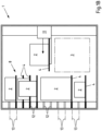
- a shipment warehouse 1 for accepting, temporarily storing and returning shipments 2 is shown.
- the shipments 2 are handed over to a transfer device 3 for acceptance by the shipment warehouse 1 .
- a carrier element 4 in the form of a tray is already kept ready there, onto which the shipment 2 to be accepted is placed via an opening 5 in the shipment warehouse 1 in the transfer device 3 .
- a detection device 6 now detects, for example by means of at least one optical sensor, a height dimension of the shipment 2 and shipment information, for example relating to the addressee or a shipment code.
- the detection device 6 can include at least one, if necessary optical, sensor or scanner.
- the mailing information is used, for example, to ensure that a very specific mailing 2 can always be output from the mailing warehouse 1, and can be stored in a barcode 7 on the mailings 2, for example. It is also conceivable to store the shipment information in a radio frequency identification tag (RFID tag) or a near field communication tag (NFC tag) attached to the shipment. Reading directions for such tags are known and available and can use a local radio network, for example.
- RFID tag radio frequency identification tag
- NFC tag near field communication tag
- the detection of the height dimension is used for the space-saving arrangement of the shipment 2 and the carrier element 4 in at least one shelf system 8 of the shipment warehouse 1.
- the height dimension and the shipment information are recorded and processed by a control device 9 for controlling the shipment warehouse 1. So that the mail items 2 can be placed in the transfer device 3 in any orientation, at least one detection device 6 can be arranged on several sides of the transfer device 3 if necessary.
- the mailing information can also be transmitted via a control panel 10 or electronically. When the shipment information is transmitted electronically, it can be transmitted in the form of a code, for example.
- the transmission can be carried out via a local radio network or a mobile radio network, in particular Global System for Mobile Communication (GSM), Universal Mobile Telecommunications System (UMTS) and/or Long Term Evolution (LTE), Bluetooth or Wireless Local Area Network (WLAN).
- GSM Global System for Mobile Communication
- UMTS Universal Mobile Telecommunications System
- LTE Long Term Evolution
- WLAN Wireless Local Area Network
- At least one width dimension of the carrier elements 4 is reduced as required after the mail items 2 have been accepted by the carrier elements 4 until the corresponding width dimension is adapted to the width dimension of the associated mail item 2 in a predetermined manner.
- the width of the carrier elements 4 corresponds at least essentially to the width of the associated mail items 2 or is only slightly larger, in particular by a certain amount, than the corresponding width of the associated mail items 2.
- the carrier element 4 is gripped by a transport device 11, which in the illustrated and therefore preferred exemplary embodiment is a portal robot that has three movements can perform mutually perpendicular spatial directions.
- the transport device 11 is controlled by the control device 9 which uses the height dimension of the shipment 2 and the width dimension of the shipment 2 to determine a suitable, free storage location for the shipment 2 in the control system 8 of the shipment warehouse 1 .
- the height dimension and the width dimension of the shipment 2 determine how much space must be available in the shelf system 8 for the shipment 2, at least in two spatial directions, in particular horizontally in the width direction and vertically.
- These storage positions are determined by holding elements 12 which define different holding planes 13 arranged vertically one above the other.
- the holding elements 12 are formed by receptacles in the form of grooves that extend at least substantially across the width of the control system 8 .
- the holding elements 12 are preferably aligned horizontally.
- the carrier elements 4 can be positioned along the holding elements 12 in any storage positions. In the vertical direction, however, the carrier elements 4 can only be positioned on the corresponding holding planes 13 in the holding elements 12 . In the case of the shipment store 1 shown and preferred in this respect, this is done by inserting the carrier element 4 into the holding elements 12 in the form of a receptacle or groove.
- the vertical extension of the carrier element 4 is preferably slightly smaller than the vertical extension of the holding elements 12.
- the carrier element 4 is then held in the holding element 12 in a form-fitting manner.
- the transport device 11 can therefore be detached from the carrier element 4 and, for example, move another carrier element 4 to its storage position specified by the control device 9 .
- the control device 9 specifies the respective storage positions in such a way that the available storage space of the shelving system 8 is utilized as well as possible. This means that the control device 9 has information about which carrier element 4 is stored with which shipment 2 at which storage position of the shelf system 8 . If this is known, it is also known which spaces of the shelving system 8 are still free.
- Mail items 2 are output in such a way that the control device 9 is prompted to deliver a specific mail item 2 or to deliver specific items of mail 2 .
- This can be done by entering information linked to the respective shipment 2 , in particular by entering a code, for example on the control panel 10 of the shipment warehouse 1 .
- the information for outputting can also be transmitted electronically, if necessary via a local radio network or a mobile radio network, in particular Global System for Mobile Communication (GSM), Universal Mobile Telecommunications System (UMTS) and/or Long Term Evolution ( LTE), Bluetooth or Wireless Local Area Network (WLAN).
- GSM Global System for Mobile Communication
- UMTS Universal Mobile Telecommunications System
- LTE Long Term Evolution
- WLAN Wireless Local Area Network
- the corresponding shipment 2 can then be received by a collector.
- the carrier element 4 preferably remains in the transfer device 3 for receiving a further shipment 2 or is temporarily stored in the carrier element store 14 until it is required again for storing a shipment 2 in the shipment warehouse 1 .
- several mail items 2 can also be output one after the other without the carrier elements 4 accumulating in the transfer device 3 .
- a carrier element 4 can be removed from the carrier element store 14 and transferred to the transfer device 3 for acceptance, at least for the acceptance of the second and each additional item of mail 2 a shipment 2 are spent.
- control device 9 If the control device 9 recognizes that there are many storage positions in the rack system 8 for receiving only narrow or short shipments 2 due to repeated acceptance and output, the control device 9 can partially rearrange the carrier elements 4 and assign them a different storage position to which the corresponding carrier elements 4 are then consumed by means of the transport device 11. In this way, spaces can be created in the control system 8 for accommodating tall and/or wide mail items 2, for example in the event that such mail items 2 are to be stored.
- the re-sorting described can take place as required, while the mail store 1 is neither requested to issue a mail item 2 nor has a mail item 2 in the transfer device 3 for storage in the mail store 1 .
- transfer devices 3 In order to speed up the acceptance and delivery of mail items 2, instead of a single transfer device 3, several, in particular two, transfer devices can also be provided. Alternatively or additionally, for the same reason, instead of a single transport device 11, several, in particular two, transport devices can be provided, each of which can more preferably be a gantry robot.
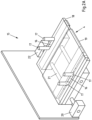
- the adjustment device 15 of the consignment warehouse is off 1 shown, with which the width of the carrier elements 4 are adapted to the width of the mail items 2 received in the transfer device 3 .
- the adjustment device 15 is integrated into the transfer device 3 in the shipment storage facility 1 that is shown and is preferred in this respect.
- the carrier elements 4 have recesses 16 through which the stops 17 of the adjustment device 15 reach and project upwards relative to the carrier element 4 . This is also not necessary if, for example, the stops 17 were provided laterally next to the carrier elements 4 .
- the carrier elements 4 have two carrier element sections 18,19. In principle, however, there could also be more carrier element sections.
- the carrier element sections 18, 19 can be pushed together and pulled apart again, with one carrier element section 18 being partially accommodated in the other carrier element section 19, which is preferred but not mandatory. By pushing the carrier element sections 18, 19 into one another, the width of the carrier element 4 is reduced overall.
- the carrier element 4 is pushed together by means of an electric motor drive 20 which, for example, comprises a spindle drive with a spindle 21 or can be designed as a linear drive.
- an electric motor drive 20 which, for example, comprises a spindle drive with a spindle 21 or can be designed as a linear drive.
- This information is processed by the control device 9 in order to assign the carrier element 4 to a storage position in the shelving system 8 that is wide enough to accommodate the carrier element 4 .
- the control device 9 ensures that the storage position is allocated enough space to accommodate the carrier element 4 and the corresponding shipment 2 therein.
- Distance or proximity sensors could also be attached to the stops 17 in order to end the pushing together of the carrier element 4 before the stops 17 come into contact with the mail items 2 .
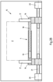
- FIG. 3A-B alternative support elements 23 and alternative shelving system 24 are shown.
- the support elements 23 have two support element sections 25, 26, of which a support element section 28 has two button elements 27 that protrude backwards parallel to the support element 23. These can be hung in a form-fitting manner in corresponding slots 28 of the holding elements 29 which are distributed along the holding elements 29 at regular intervals.
- the button elements 27 must then be lowered into the holding elements 29 and, in order to remove the carrier element 23, first moved upwards again before the carrier element 23 can be pulled horizontally out of the holding element 29. This prevents the carrier elements 23 from accidentally slipping out of the holding elements 29 , but it is accepted that the carrier elements 23 can only be arranged in a specific grid of the shelving system 24 . This is the case with the holding elements 12 in the form of continuous grooves as in the case of the shelving system 8 according to FIG Figures 1A-B not the case.
- the carrier elements 4 can be positioned steplessly next to one another in the groove-shaped holding elements 12 .
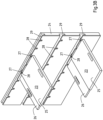
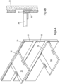
- FIGS. 4A-B alternative support elements 30 and alternative shelving systems 31 are shown.
- the carrier elements 30 have U-shaped retaining strips 32 on the the holding elements 33 of the associated shelving system 31, in the form of continuous ribs, can be attached.
- This configuration of support element 30 and shelf system 31 represents a compromise between the configurations according to FIG Figures 1A-B and 3A-B
- the support elements 30 can be fixed next to one another on a holding element 33 without taking into account a grid, the support elements 30 being simultaneously secured against accidentally slipping out horizontally.
- control system 34 as in the figure 5 shown by way of example, have holding elements 35 in the form of pivoting arms which are swung out into a use position in order to hold a support element and are swung into a non-use position when the holding elements 35 are not required for holding support elements.
Description
Die Erfindung betrifft ein Sendungslager zum separaten Übernehmen, Zwischenlagern und Ausgeben einer Vielzahl von unterschiedliche Abmessungen aufweisenden Sendungen. Ferner betrifft die Erfindung ein Verfahren zum Betrieb eines Sendungslagers zum separaten Übernehmen, Zwischenlagern und Ausgeben einer Vielzahl von unterschiedliche Abmessungen aufweisenden Sendungen.The invention relates to a mail store for the separate acceptance, intermediate storage and output of a large number of mail items having different dimensions. Furthermore, the invention relates to a method for operating a mail store for the separate acceptance, temporary storage and output of a large number of mail items having different dimensions.
Sendungslager und Verfahren zu deren Betrieb sind in unterschiedlichen Ausführungen bekannt. Dabei werden in der Regel Sendungen an das Sendungslager übergeben, im Sendungslager zwischengelagert und anschließend wieder ausgegeben. Wenn die Sendungen unterschiedliche Größen aufweisen ist es zudem bekannt die Sendungen in Abhängigkeit ihrer Größe bestimmten Lagerorten zuzuweisen. Um einen unberechtigten Zugriff auf die Sendungen zu vermeiden, kann das Verbringen an die Lagerorte zum Zwischenspeichern der Sendungen und das anschließende Ausgeben der Sendungen automatisiert werden. Dabei wird beim Zwischenlagern der Sendungen oftmals versucht, der zum Zwischenspeichern der Sendungen zur Verfügung stehende Raum möglichst effizient zu nutzen. Dazu werden die Sendungen meist unterschiedlich großen Kompartimenten zugeordnet, je nachdem wie groß die Sendung ist. Dabei gilt grundsätzlich, dass der apparative Aufwand und der Handhabungsaufwand umso mehr ansteigt, je effizienter der zur Verfügung stehende Lagerraum ausgenutzt werden soll, ohne dass hier bereits völlig zufriedenstellende Ergebnisse erhalten werden können.Shipment storage and methods for its operation are known in different versions. As a rule, consignments are handed over to the consignment warehouse, temporarily stored in the consignment warehouse and then issued again. If the shipments have different sizes, it is also known to assign the shipments to specific storage locations depending on their size. In order to avoid unauthorized access to the shipments, the bringing to the storage locations for the intermediate storage of the shipments and the subsequent issuing of the shipments can be automated. When the mailpieces are temporarily stored, an attempt is often made to use the space available for temporarily storing the mailpieces as efficiently as possible. For this purpose, the shipments are usually assigned to compartments of different sizes, depending on the size of the shipment. In this case, it is generally the case that the expenditure on equipment and the expenditure on handling increases the more efficiently the available storage space is to be used, without completely satisfactory results being able to be obtained here.
Sendungslager der genannten Art sind beispielsweise aus der
Der vorliegenden Erfindung liegt die Aufgabe zugrunde, das Sendungslager und das Verfahren jeweils der eingangs genannten und zuvor näher beschriebenen Art derart auszugestalten und weiterzubilden, dass das Zwischenlagern von Sendungen platzsparend und zugleich mit geringem Aufwand erfolgen kann.The present invention is based on the object of designing and developing the mail item store and the method of the type mentioned at the outset and described in more detail above in such a way that the intermediate storage of mail items can take place in a space-saving manner and at the same time with little effort.
Diese Aufgabe ist gemäß Anspruch 1 durch ein Sendungslager gelöst, das zum separaten Übernehmen, Zwischenlagern und Ausgeben einer Vielzahl von unterschiedliche Abmessungen aufweisenden Sendungen ausgebildet ist, mit einer Übergabeeinrichtung zum separaten Übernehmen von Sendungen und zum Übergeben der Sendungen an separate Trägerelemente, insbesondere Tabletts, des Sendungslagers, mit einer Erfassungseinrichtung zum Erfassen von Höhenabmessungen der Sendungen, mit einem Regalsystem umfassend in vertikaler Richtung übereinander angeordneten und Halteebenen definierenden Halteelementen, wobei die Haltelemente und Trägerelemente so korrespondierend ausgebildet sind, dass einerseits auf wenigstens zwei angrenzenden Halteebenen zwei jeweils eine Sendung tragende Trägerelemente in vertikaler Richtung übereinander gehalten sein können und dass andererseits auf wenigstens einer Halteebene ein Trägerelement mit einer Sendung höher als der vertikale Abstand zur nächsthöheren Halteebene gehalten sein kann, wobei wenigstens eine Steuereinrichtung zum Zuweisen von Sendungen aufweisenden Trägerelementen in vertikaler Richtung übereinander zu unterschiedlichen Halteelementen und/oder Lagerpositionen in Abhängigkeit der erfassten Höhenabmessungen der von den Trägerelementen getragenen Sendungen vorgesehen ist und wobei eine Anpassungseinrichtung zum Anpassen einer Breitenabmessung und/oder Längenabmessung der Trägerelemente an wenigstens eine Breitenabmessung und/oder Längenabmessung der zugehörigen Sendungen vorgesehen ist.According to claim 1, this object is achieved by a mail store that is designed to separately accept, temporarily store and issue a large number of mail items with different dimensions, with a transfer device for the separate acceptance of mail items and for transferring the mail items to separate carrier elements, in particular trays, of the mail storage facility, with a detection device for detecting the height dimensions of the mail items, with a racking system comprising holding elements which are arranged one above the other in the vertical direction and define holding levels, the holding elements and carrier elements being designed to correspond so that, on the one hand, on at least two adjacent holding levels, two carrier elements each carrying a mail item in can be held one above the other in the vertical direction and that on the other hand a carrier element with a mail item can be held on at least one holding level higher than the vertical distance to the next higher holding level, with at least one control device for allocating carrier elements containing mail items in the vertical direction one above the other to different holding elements and/or Storage positions are provided depending on the detected height dimensions of the mail items carried by the carrier elements and an adjustment device is provided for adjusting a width dimension and/or length dimension of the carrier elements to at least one width dimension and/or length dimension of the associated mail items.
Zudem ist die zuvor genannte Aufgabe gemäß Anspruch 9 gelöst durch ein Verfahren zum Betrieb eines Sendungslagers zum separaten Übernehmen, Zwischenlagern und Ausgeben einer Vielzahl von unterschiedliche Abmessungen aufweisenden Sendungen, vorzugsweise unter Verwendung eines Sendungslagers nach einem der Ansprüche 1 bis 8,
- bei dem Sendungen separat mit einer Übergabeeinrichtung übernommen und an separate Trägerelemente, insbesondere Tabletts, übergeben werden,
- bei dem Höhenabmessungen der Sendungen mit einer Erfassungseinrichtung erfasst werden,
- bei dem die Sendungen aufweisenden Trägerelemente mit einer Steuereinrichtung in Abhängigkeit der erfassten Höhenabmessungen in vertikaler Richtung übereinander vorgesehenen Halteebenen definierenden Halteelemente eines Regalsystems so zugewiesen werden, dass auf wenigstens einigen Halteebenen Trägerelemente mit einer Sendung höher als der vertikale Abstand zur nächst höheren Halteebene in vertikaler Richtung übereinander angeordnet werden und
- bei dem eine Breitenabmessung und/oder Längenabmessung der Trägerelemente in einer Anpassungseinrichtung an eine Breitenabmessung und/oder Längenabmessung der zugehörigen Sendungen angepasst werden.
- in which shipments are accepted separately with a transfer device and transferred to separate carrier elements, in particular trays,
- in which the height dimensions of the mail items are recorded with a recording device,
- in which the carrier elements containing the mail items are assigned to holding elements of a shelving system that define holding levels one above the other in a vertical direction, depending on the detected height dimensions, such that on at least some holding levels, carrier elements with a mail item are higher than the vertical distance to the next higher holding level in the vertical direction one above the other be arranged and
- in which a width dimension and/or length dimension of the carrier elements are adapted in an adjustment device to a width dimension and/or length dimension of the associated mail items.
Das Sendungslager kann zum separaten Übernehmen, Zwischenlagern und Ausgeben einer Vielzahl von unterschiedliche Abmessungen aufweisenden Sendungen genutzt werden. Dabei dient der Übernahme der Sendungen durch das Sendungslager eine Übergabeeinrichtung, mit der die Sendungen separat und insbesondere nacheinander Übernommen werden können. Zudem werden die Sendungen über die Übergabereinrichtung, insbesondere nacheinander, an separate Trägerelemente, wie etwa Tabletts, übergeben. Dabei ist eine Erfassungseinrichtung vorgesehen, die wenigstens eine Höhenabmessung der Sendungen erfasst. So können die Sendungen separat mit den Trägerelementen und in Abhängig von der jeweiligen Höhenabmessung zum Lagerort in einem Regalsystem transportiert werden.The shipment warehouse can be used for the separate acceptance, intermediate storage and output of a large number of shipments having different dimensions. A transfer device with which the shipments can be taken over separately and, in particular, one after the other, serves to take over the shipments through the shipment warehouse. In addition, the mail items are transferred to separate carrier elements, such as trays, via the transfer device, in particular one after the other. A detection device is provided that detects at least one height dimension of the mail items. In this way, the shipments can be transported separately with the carrier elements and depending on the respective height dimension to the storage location in a rack system.
Das Regalsystem weist dabei in vertikaler Richtung übereinander angeordnete Halteelement auf, die jeweils übereinander angeordnete Halteebenen definieren. Die Halteelemente sind dabei so ausgebildet, dass in vertikaler Richtung übereinander auf jeder Halteebene ein Trägerelement mit einer Sendung angeordnet werden kann. Die Halteelemente sind aber zudem so ausgebildet, dass auf wenigstens einigen Halteebenen Trägerelemente mit einer Sendung angeordnet werden können, die höher ist als der vertikale Abstand zur nächst höheren Halteebene in vertikaler Richtung, ohne dabei mit dem Halteelement der nächst höheren Halteebene zu kollidieren. Im Übrigen ist noch eine Steuereinrichtung vorgesehen, die die Sendungen aufweisenden Trägerelemente in Abhängigkeit der erfassten Höhenabmessungen der von den Trägerelementen getragenen Sendungen in vertikaler Richtung übereinander zu unterschiedlichen Halteelementen und/oder Lagerpositionen zuordnet.The shelving system has holding elements which are arranged one above the other in the vertical direction and which each define holding planes which are arranged one above the other. The holding elements are designed in such a way that a carrier element with a mail item can be arranged one above the other in the vertical direction on each holding plane. However, the holding elements are also designed in such a way that carrier elements with a shipment can be arranged on at least some holding levels, which is higher than the vertical distance to the next higher holding level in the vertical direction, without colliding with the holding element of the next higher holding level. A control device is also provided, which assigns the carrier elements containing the mail items to different holding elements and/or storage positions in the vertical direction, one above the other, depending on the detected height dimensions of the mail items carried by the carrier elements.
So wird beispielsweise ein Trägerelement einer Halteebene so zugeordnet, dass die getragene Sendung gerade unter ein weiteres Trägerelement passt. Dies bedeutet beispielsweise, dass zwischen dem Trägerelement und der vertikal darunter angeordneten Sendung ein vertikaler Abstand existiert, der geringer ist als der Abstand zwischen der Halteebene des oberen Trägerelements und der nächsten darunter angeordneten Halteebene. Es kann so auch eine Sendung mit dem zugehörigen Trägerelement so zwischen zwei andere Sendungen im Regelsystem platziert werden, dass der Lagerraum in vertikaler Richtung möglichst vollständig ausgenutzt wird. Da die Höhenabmessung der jeweiligen Sendung und die des Trägerelements bekannt ist, kann die Steuereinrichtung eine platzsparende Anordnung der entsprechenden Trägerelemente im Regalsystem errechnen.For example, a carrier element is assigned to a holding level in such a way that the item being carried just fits under another carrier element. This means, for example, that there is a vertical distance between the carrier element and the shipment arranged vertically below it, which is less than the distance between the holding plane of the upper carrier element and the next holding plane arranged below it. A shipment with the associated carrier element can also be placed between two other shipments in the control system in such a way that the storage space is utilized as completely as possible in the vertical direction. Since the height dimension of the respective shipment and that of the carrier element is known, the control device can calculate a space-saving arrangement of the corresponding carrier elements in the shelf system.
Damit die Sendungen auch in horizontaler Richtung platzsparend nebeneinander angeordnet werden können, beispielsweise in einer gemeinsamen Halteebene, kann die Abmessung der Trägerelemente wenigstens in einer Richtung an die Abmessungen der Sendungen angepasst werden. Hierzu wird sich einer Anpassungseinrichtung bedient, die der Anpassung einer Breitenabmessung und/oder Längenabmessung von Trägerelementen an wenigstens eine Breitenabmessung und/oder Längenabmessung einer Sendung dient, welche von dem jeweiligen Trägerelement getragen wird oder werden soll. Dabei kann die Breitenabmessung und/oder Längenabmessung der Trägerelemente in einfacher Weise durch Einschieben von Trägerelementabschnitten gegeneinander eingestellt werden. Die Anpassung der Trägerelemente an die Sendungen kann dabei so erfolgen, dass die Anpassungseinrichtung und/oder das entsprechende Trägerelement und/oder die Anpassungseinrichtung wenigstens einen Anschlag zur Anlage an die zugehörige Sendung aufweist. Werden die Trägerelemente nun in wenigstens eine Richtung gegeneinander eingeschoben, gelangt der wenigstens eine Anschlag irgendwann in Anlage an die Sendung. Durch diese Anlage kann das weitere Einschieben der Trägerelementabschnitte gegeneinander beendet werden. Beispielsweise kann ein Berührungssensor den Kontakt mit der Sendung erfassen oder es kann ein Abstandssensor genutzt werden, um den Abstand zur Sendung zu erfassen. Es kann aber auch eine Leistung, eine Kraft und/oder ein Drehmoment des motorischen Antriebs zum Einschieben der Trägerelementabschnitte gegeneinander erfasst werden. Wenn dabei erkannt wird, dass vorzugsweise durch die Anlage des wenigstens einen Anschlags an der Sendung ein bestimmter Grenzwert überschritten wird, kann das weitere Einschieben der Trägerelementabschnitte gegeneinander durch eine Steuereinrichtung oder selbstständig beendet werden.So that the mail items can also be arranged next to one another in a space-saving manner in the horizontal direction, for example in a common holding plane, the dimensions of the carrier elements can be adapted to the dimensions of the mail items at least in one direction. For this purpose, an adjustment device is used, which adjusts a width dimension and/or length dimension of carrier elements to at least one width dimension and/or length dimension a shipment is used, which is or should be carried by the respective carrier element. The width dimension and/or length dimension of the carrier elements can be adjusted in a simple manner by pushing in carrier element sections against one another. The carrier elements can be adapted to the mail items in such a way that the adjustment device and/or the corresponding carrier element and/or the adjustment device has at least one stop for contact with the associated mail item. If the carrier elements are now pushed in against one another in at least one direction, the at least one stop eventually comes into contact with the shipment. This contact can stop the further pushing in of the carrier element sections against one another. For example, a touch sensor can detect contact with the shipment, or a distance sensor can be used to detect the distance from the shipment. However, it is also possible to record a power, a force and/or a torque of the motor drive for pushing in the carrier element sections against one another. If it is recognized that a certain limit value is exceeded, preferably due to the contact of the at least one stop on the mail item, the further pushing in of the carrier element sections against one another can be terminated by a control device or independently.
In diesem Zusammenhang versteht es sich, dass die Trägerelemente bevorzugt in einer Richtung und/oder in zwei senkrecht zueinander stehenden Richtungen gegeneinander eingeschoben werden können. Dies ist jedoch nicht zwingend. Zudem können die Trägerelemente auch wieder in die entgegengesetzte Richtung bzw. die entgegengesetzten Richtungen wieder ausgezogen werden. So können die Trägerelemente anschließend wieder zur Aufnahme weiterer Sendungen genutzt, mithin wiederverwendet, werden. Darüber hinaus kann es bevorzugt sein, dass wenigstens ein Trägerelementabschnitt in einen korrespondierenden Trägerelementabschnitt eingeschoben wird, um die Breite und/oder die Länge des Trägerelements zu verringern. Aber auch dies ist nicht zwingend. Die Trägerelementabschnitte können auch so miteinander verbunden sein, dass sie gegeneinander verschiebbar sind, ohne ineinander einzugreifen. Die Trägerelementabschnitte können so beispielsweise übereinander geschoben und/oder gestaucht, etwa zusammengedrückt oder zusammengefaltet werden.In this context, it goes without saying that the carrier elements can preferably be pushed in towards one another in one direction and/or in two directions which are perpendicular to one another. However, this is not mandatory. In addition, the support elements can also be pulled out again in the opposite direction or directions. In this way, the carrier elements can then be used again to hold further mail items, and therefore reused. In addition, it can be preferred that at least one carrier element section is inserted into a corresponding carrier element section in order to reduce the width and/or the length of the carrier element. But this is not mandatory either. The carrier element sections can also be connected to one another in such a way that they can be displaced in relation to one another without engaging in one another. The Carrier element sections can thus be pushed over one another and/or compressed, for example pressed together or folded together.
Vorliegend werden unter Sendungen grundsätzlich unterschiedliche Gegenstände verstanden, die vorzugsweise mit überschaubarem Aufwand transportiert werden können. Insbesondere können die Sendungen als Stückgut vorliegen. Dabei kommen Gegenstände des täglichen Bedarfs, wie Verbrauchsmaterialien oder Lebensmittel ebenso in Frage wie technische Gegenstände und Gerätschaften. In vielen Fällen handelt es sich bei den Sendungen um Sendungen eines Postunternehmens, die als Postsendungen bezeichnet werden können. Bedarfsweise handelt es sich bei den Sendungen um Briefsendungen, Paketsendungen und/oder Flyer. Dabei umfassen Paketsendungen auch Päckchen, während Flyer auch Prospekte, Broschüren und Zeitschriften sein können. Zudem kann eine Briefsendung neben einem Brief auch eine Postkarte sein. Bei Paketsendungen und anderen Sendungen handelt es sich in vielen Fällen um umverpackte Güter, wobei dann die Sendung die Verpackung und das darin verpackte Gut umfassen.In the present case, consignments are fundamentally understood to mean different objects that can preferably be transported with manageable effort. In particular, the shipments can be present as general cargo. Objects of daily use, such as consumables or food, come into question as well as technical objects and equipment. In many cases, the shipments are shipments from a postal company, which may be referred to as postal items. If necessary, the shipments are letters, parcels and/or flyers. Parcel shipments also include small packages, while flyers can also be prospectuses, brochures and magazines. In addition, a letter can also be a postcard in addition to a letter. Parcel shipments and other shipments are in many cases repackaged goods, in which case the shipment includes the packaging and the goods packed in it.
Der besseren Verständlichkeit halber und zur Vermeidung von unnötigen Wiederholungen werden nachfolgend das Sendungslager und das Verfahren gemeinsam beschrieben, ohne jeweils im Einzelnen zwischen dem Sendungslager, der Anpassungseinrichtung und dem Verfahren zu unterscheiden. Für den Fachmann ergibt sich jedoch anhand des Kontextes, welches Merkmal jeweils für das Sendungslager, die Anpassungseinrichtung und das Verfahren besonders bevorzugt ist.For the sake of better comprehension and to avoid unnecessary repetitions, the mailpiece store and the method are described together below without making a detailed distinction between the mailpiece store, the adjustment device and the method. However, for the person skilled in the art it is clear from the context which feature is particularly preferred in each case for the shipment warehouse, the adjustment device and the method.
Bei dem Sendungslager ist eine Anpassungseinrichtung zum Anpassen einer Breitenabmessung und/oder Längenabmessung der Trägerelemente an wenigstens eine Breitenabmessung und/oder Längenabmessung der zugehörigen Sendungen vorgesehen. Durch die Anpassungseinrichtung kann gewährleistet werden, dass auch schmale und/oder kurze Sendungen mit recht geringem Abstand zueinander im Regalsystem zwischengelagert werden können, ohne dass es dabei zu einer unerwünschten Beeinträchtigung oder Kollision der Trägerelemente untereinander kommt. Dabei ist es konstruktiv im Hinblick auf die Trägerelemente und/oder im Hinblick auf die Anpassungseinrichtung besonders zweckmäßig, wenn die Breitenabmessung und/oder Längenabmessung der Trägerelemente durch Ausziehen und/oder Einschieben von Trägerelementabschnitten gegeneinander einstellbar ist. Um sicherzustellen, dass die Breitenabmessung und/oder Längenabmessung der Trägerelemente relativ zur jeweiligen Sendung nicht zu sehr verringert werden, mithin ein sicheres Tragen der Sendungen durch die Trägerelemente nicht zu gefährden, kann die Anpassungseinrichtung und/oder die Trägerelemente und/oder die Anpassungseinrichtung wenigstens einen Anschlag zur Anlage an die zugehörige Sendung beim Einschieben von Trägerelementabschnitten und Abschaltmittel zum Beenden des weiteren Einschiebens der Trägerelementabschnitte aufweisen. Dabei kann das weitere Einschieben der Trägerelementabschnitte wahlweise bereits vor einem Kontakt des Anschlags mit der Sendung und/oder erst nach dem Kontakt des Anschlags mit der Sendung beendet werden. Dies ist dann abhängig davon, wie der Kontakt oder der bevorstehende Kontakt des Anschlags mit der Sendung erfasst bzw. überwacht wird. Werden beispielsweise Abstandssensoren oder Näherungssensoren verwendet, kann das Einschieben der Trägerelemente schon vor einem Anschlag der Sendung an einem Anschlag beendet werden. Auf den Anschlag und ein Abschalten des Einschiebens der Trägerelemente erst nach einem Kontakt zwischen Sendung und Anschlag kann aber ergänzend gesetzt werden, wenn der Abstandssensor oder Näherungssensor nicht wie gewünscht funktionieren sollte.An adjustment device for adjusting a width dimension and/or length dimension of the carrier elements to at least one width dimension and/or length dimension of the associated mail items is provided in the mail store. The adjustment device can ensure that even narrow and/or short mail items are rightly can be stored temporarily in the shelving system at a small distance from one another without the support elements being adversely affected or colliding with one another. In terms of construction, it is particularly expedient with regard to the carrier elements and/or with regard to the adjustment device if the width dimension and/or length dimension of the carrier elements can be adjusted relative to one another by pulling out and/or pushing in carrier element sections. In order to ensure that the width dimension and/or length dimension of the carrier elements are not reduced too much relative to the respective item of mail, and thus do not jeopardize the safe carrying of the items of mail by the carrier elements, the adjustment device and/or the carrier elements and/or the adjustment device can have at least one Having a stop for contacting the associated shipment when inserting carrier element sections and disconnecting means for terminating the further insertion of the carrier element sections. The further insertion of the carrier element sections can optionally be ended before the stop comes into contact with the mail item and/or only after the stop comes into contact with the mail item. This then depends on how the contact or imminent contact of the attack with the broadcast is recorded or monitored. If, for example, distance sensors or proximity sensors are used, the insertion of the carrier elements can be completed before the mail item hits a stop. However, the stop and switching off the insertion of the carrier elements only after contact between the mail item and the stop can also be used if the distance sensor or proximity sensor does not work as desired.
Insbesondere wenn die Breitenabmessungen und/oder die Längenabmessungen der Trägerelemente an die Abmessungen der Sendungen angepasst werden, bietet es sich an, dass die Steuereinrichtung zum Zuweisen von Sendungen aufweisenden Trägerelementen zu Lagerpositionen ausgebildet ist. Insbesondere können die Trägerelemente so einer gemeinsamen Halteebene zugewiesen werden, und zwar in Abhängigkeit der Breitenabmessung und/oder Längenabmessung der Trägerelemente und/oder der Sendungen nebeneinander. Die Steuereinrichtung erhält dazu Informationen betreffend der entsprechenden Breitenabmessung und/oder Längenabmessung und des Weiteren Informationen über die noch zur Verfügung stehenden und/oder die bereits belegten Lagerorte. Dies erlaubt der Steuereinrichtung dann die entsprechenden Trägerelementen recht eng nebeneinander anzuordnen, ohne dass die Trägerelemente oder Sendungen kollidieren und ohne zu viel Lagerraum dazwischen ungenutzt zu lassen.In particular, if the width dimensions and/or the length dimensions of the carrier elements are adapted to the dimensions of the mail items, it makes sense for the control device to be designed to allocate carrier elements containing mail items to storage positions. In particular, the carrier elements can thus be assigned to a common holding plane, specifically depending on the width dimension and/or length dimension of the carrier elements and/or the mail items next to one another. The control device receives this Information regarding the corresponding width dimension and/or length dimension and further information about the storage locations still available and/or already occupied. This then allows the control device to arrange the corresponding carrier elements very closely next to one another without the carrier elements or mail items colliding and without leaving too much unused storage space in between.
Die effiziente Ausnutzung des Lagerraums muss sich jedoch nicht auf das Einlagern neuer Sendungen beschränken. Vielmehr wird durch das Ausgeben von Sendungen wieder Lagerraum frei. So kann eine effizientere Ausnutzung des Lagerraums bedarfsweise auch dadurch erreicht werden, dass die Trägerelemente des Regalsystems wenigstens teilweise umsortiert werden. So kann beispielsweise ein größerer zusammenhängender Lagerraum bereitgestellt werden, in dem nachfolgend Sendungen wieder mit hoher Flexibilität zwischengelagert werden können, ohne unnötig Lagerraum ungenutzt zu lassen. Die Steuereinrichtung kann also zum effizienteren Ausnutzen des Lagerraums zum Verstellen von wenigstens eine Sendung tragenden Trägerelements von einer Lagerposition zu einer anderen Lagerposition ausgebildet sein.However, the efficient use of storage space does not have to be limited to storing new shipments. Rather, storage space is freed up again by issuing shipments. If necessary, more efficient utilization of the storage space can also be achieved in that the support elements of the shelving system are at least partially rearranged. For example, a larger contiguous storage room can be provided in which subsequent shipments can be temporarily stored again with a high degree of flexibility, without leaving storage space unnecessarily unused. The control device can thus be designed for more efficient utilization of the storage space for moving carrier elements carrying at least one item of mail from one storage position to another storage position.
Alternativ oder zusätzlich kann die Steuereinrichtung dazu ausgebildet sein, Sendungsinformationen, Höhenabmessungen, Breitenabmessung und/oder Längenabmessung der Sendungen, mit den den Sendungen zugeordneten Trägerelementen und/oder den den Sendungen und/oder Trägerelementen zugeordneten Lagerpositionen zu verknüpfen. So kann eine bestimmte Sendung beispielsweise sicher wieder ausgegeben werden. Dies ist insbesondere dann der Fall, wenn eine Sendungsinformation dem zugehörigen Trägerelement zugeordnet ist und die Steuereinrichtung über die aktuelle Lagerposition des entsprechenden Trägerelements informiert ist. Alternativ oder zusätzlich kann auch eine Zuordnung der Sendungsinformationen zu den jeweiligen Lagerpositionen der die Sendungen tragenden Trägerelemente erfolgen. Auch dann ist der Steuereinrichtung stets bekannt, an welcher Lagerposition sich das Trägerelement befindet, welches eine bestimmte Sendung trägt. Sendungsinformationen können dabei beispielsweise den Adressaten der Sendung und/oder den Verwender der Sendung betreffen und/oder bezeichnen. Es kann sich bei der Sendungsinformation alternativ oder zusätzlich auch um einen, vorzugsweise individuellen, Sendungscode und/oder weitere Informationen handeln. Wenn Höhenabmessungen, Breitenabmessung und/oder Längenabmessung der Sendungen mit Trägerelementen und/oder den den Sendungen und/oder Trägerelementen zugeordneten Lagerpositionen zu verknüpfen sind, kann die Steuereinrichtung in einfacher Weise ermitteln an welchen Orten im Regalsystem noch Lagerraum zum Zwischenlagern weiterer Sendungen bereitsteht. Je umfangreicher die Abmessungen der entsprechenden Sendungen bekannt sind, umso genauer kann die Steuereinrichtung ermitteln, wie groß der an bestimmten Orten im Regelsystem noch zur Verfügung stehende Laderaum ist. Dementsprechend kann auch der Laderaum des Regalsystems effizienter ausgenutzt werden.Alternatively or additionally, the control device can be designed to link shipment information, height dimensions, width dimensions and/or length dimensions of the shipments with the carrier elements assigned to the shipments and/or the storage positions assigned to the shipments and/or carrier elements. For example, a certain shipment can be safely returned. This is the case in particular when item of mailing information is assigned to the associated carrier element and the control device is informed of the current storage position of the corresponding carrier element. Alternatively or additionally, the mailing information can also be assigned to the respective storage positions of the carrier elements carrying the mailings. Even then, the control device is always known at which storage position the carrier element is located, which has a specific shipment carries. Mailing information can relate to and/or designate the addressee of the mailing and/or the user of the mailing, for example. Alternatively or additionally, the shipment information can also be a, preferably individual, shipment code and/or other information. If the height dimensions, width dimensions and/or length dimensions of the shipments are to be linked to carrier elements and/or the storage positions assigned to the shipments and/or carrier elements, the control device can easily determine at which locations in the shelving system storage space is still available for the intermediate storage of further shipments. The more extensively the dimensions of the corresponding shipments are known, the more precisely the control device can determine how large the loading space that is still available at certain locations in the control system is. Accordingly, the loading space of the shelving system can also be used more efficiently.
Zum einfachen und zuverlässigen Erfassen von Abmessungen der Sendungen kann die Erfassungseinrichtung einen Abmessungsscanner zum Erfassen von Höhenabmessungen, Breitenabmessung und/oder Längenabmessung der Sendungen aufweisen. Der Abmessungsscanner kann beispielsweise über wenigstens einen optischen Sensor die entsprechende Abmessung erfassen. Es kann aber auch wenigstens ein Abstandssensor, ein induktiver Sensor und/oder ein kapazitiver Sensor genutzt werden. Alternativ oder zusätzlich kann die Erfassungseinrichtung einen Scanner aufweisen, der die in einem an der Sendung vorgesehenen Speicher gespeicherten Sendungsinformationen ausliest. Je nach Art des Speichers kann der Scanner beispielsweise ein optischer Sensor, ein Barcode-Scanner, ein RFID-Lesegerät und/oder ein NFC-Lesegerät sein, zum Erfassen von Sendungsinformationen, vorzugsweise betreffend den Adressaten, den Verwender, einen, vorzugsweise individuellen, Sendungscode, die Höhenabmessung, die Breitenabmessung und/oder die Längenabmessung. Im Falle der Höhenabmessung, der Breitenabmessung und/oder der Längenabmessung kann diese also an anderer Stelle erfasst und in den Speicher, etwa einen Barcode, an der Sendung geschrieben werden. Die Höhenabmessung, die Breitenabmessung und/oder die Längenabmessung der Sendung kann dann durch Auslesen des Speichers erhalten werden, ohne dass dabei die wenigstes eine Abmessung der Sendung tatsächlich messtechnisch ermittelt werden muss.For the simple and reliable detection of dimensions of the mailpieces, the detection device can have a dimension scanner for detecting height dimensions, width dimensions and/or length dimensions of the mailpieces. The dimension scanner can, for example, record the corresponding dimension via at least one optical sensor. However, at least one distance sensor, an inductive sensor and/or a capacitive sensor can also be used. Alternatively or additionally, the detection device can have a scanner that reads out the mailing information stored in a memory provided on the mailing. Depending on the type of memory, the scanner can be, for example, an optical sensor, a barcode scanner, an RFID reader and/or an NFC reader for capturing shipment information, preferably relating to the addressee, the user, a preferably individual shipment code , the height dimension, the width dimension and/or the length dimension. In the case of the height dimension, the width dimension and/or the length dimension, this can therefore be recorded at a different point and written into the memory, for example a barcode, on the mailpiece. The height dimension, the width dimension and/or the length dimension of the shipment can then be Reading out the memory can be obtained without the least one dimension of the shipment actually having to be determined metrologically.
Um die Sendungen tragenden Trägerelemente von der Übergabeeinrichtung zu den entsprechenden Lagerpositionen im Regalsystem zu transportieren und/oder die entsprechenden Trägerelemente von den Lagerpositionen zurück zu der Übergabeeinrichtung transportieren zu können, kann eine Transporteinrichtung vorgesehen sein. Dabei bietet es sich aus Gründen der konstruktiven Einfachheit und des flexiblen Handlings der Trägerelemente an, wenn die Transporteinrichtung ein Portalroboter zum Verstellen der Trägerelemente wenigstens in zwei senkrecht zueinander stehenden Raumrichtungen aufweist. Der Portalroboter kann letztlich schnell und präzise sehr unterschiedliche Lagerpositionen abfahren, um dort Trägerelemente zu hinterlassen und/oder abzuholen. Mithin bietet es sich ferner besonders an, wenn der Portalroboter zum Übergeben der Trägerelemente an die Haltelemente und/oder zum Entnehmen der Trägerelemente von den Haltelementen ausgebildet ist.A transport device can be provided in order to be able to transport the carrier elements carrying mail items from the transfer device to the corresponding storage positions in the shelf system and/or to be able to transport the corresponding carrier elements from the storage positions back to the transfer device. For reasons of constructive simplicity and flexible handling of the carrier elements, it makes sense if the transport device has a portal robot for adjusting the carrier elements at least in two mutually perpendicular spatial directions. Ultimately, the portal robot can move quickly and precisely to very different storage positions in order to leave and/or pick up carrier elements there. Consequently, it is also particularly useful if the gantry robot is designed to transfer the carrier elements to the holding elements and/or to remove the carrier elements from the holding elements.
Die die Halteebenen definierenden Halteelemente können grundsätzlich auf unterschiedliche Arten ausgebildet sein. Beispielsweise kommen Schwenkarme zum Ausschwenken in eine Gebrauchsstellung und zum Einschwenken in eine Nichtgebrauchsstellung in Frage, dabei kann vorgesehen sein, dass ein Schwenkarm, zwei Schwenkarme oder eine an die Breitenabmessung, Längenabmessung und/oder Höhenabmessung der Sendung angepasste Anzahl an Schwenkarmen das entsprechende Trägerelement trägt. Bevorzugt kann es auch sein, wenn die die Halteebenen definierenden Halteelemente zwischen mehreren Gebrauchsstellungen und/oder zwischen wenigstens einer Gebrauchsstellung und wenigstens einer Nichtgebrauchsstellung verschiebbar sind und/oder dass die Halteebenen definierenden Halteelemente demontierbar ist. Dann können die Halteelemente dorthin verschoben oder dort montiert werden, wo ein Trägerelement im Regalsystem gehalten werden soll. Zudem ist es möglich, die Anzahl und Anordnung der Trägerelemente daran anzupassen, wie groß die entsprechende Sendung bzw. das Trägerelement ist. Je größer die Sendung bzw. das Trägerelement ist, desto höher kann die Zahl der verwendeten Halteelemente sein. Es kann aber auch vorgesehen sein, dass die Art der verwendeten Halteelemente an die Größe der Sendung bzw. des Trägerelements angepasst wird. Mit steigender Größe können so beispielsweise größere und/oder stabilere Halteelemente verwendet werden. Haltelemente, die von einer Nichtgebrauchsstellung in eine Gebrauchsstellung verstellt werden müssen, erfordern ebenso wie separate Haltelemente, die erst an der richtigen Stelle im Regalsystem montiert werden müssen, gleichwohl einen höheren Aufwand, und zwar in konstruktiver Hinsicht als auch hinsichtlich der Durchführung des entsprechenden Verfahrens.The holding elements that define the holding planes can basically be designed in different ways. For example, pivoting arms can be used for pivoting out into a position of use and for pivoting into a position of non-use. Provision can be made for one pivoting arm, two pivoting arms or a number of pivoting arms adapted to the width dimension, length dimension and/or height dimension of the mail item to carry the corresponding carrier element. It can also be preferred if the holding elements defining the holding planes can be displaced between a plurality of positions of use and/or between at least one position of use and at least one position of non-use and/or that the holding elements defining the holding planes can be dismantled. Then the holding elements can be moved or mounted where a support element is to be held in the shelving system. In addition, it is possible to adapt the number and arrangement of the carrier elements to the size of the corresponding shipment or the carrier element. The bigger the shipment or the carrier element is, the higher the number of holding elements used can be. However, it can also be provided that the type of holding elements used is adapted to the size of the shipment or the carrier element. As the size increases, for example, larger and/or more stable holding elements can be used. Holding elements that have to be adjusted from a non-use position to a use position, like separate holding elements that first have to be mounted at the right place in the shelving system, nevertheless require more effort, both in terms of design and in terms of carrying out the corresponding method.
Besonders einfach und flexibel ist es daher, wenn die die Halteebenen definierenden Halteelemente durch Aufnahmen zur Aufnahme von Sendungen tragenden Trägerelementen ausgebildet sind. Die Aufnahmen können dabei so ausgestaltet werden, dass nicht genutzte Aufnahmen das Zwischenspeichern von Sendungen im Regalsystem nicht behindern, etwa weil sie weder mit den benachbarten Sendungen noch den benachbarten Trägerelementen im Regalsystem kollidieren. Dies lässt sich besonders einfach und zweckmäßig erreichen, wenn die Aufnahmen in Form von Nuten ausgebildet sind. Die Aufnahmen, insbesondere die Nuten können der Einfachhalt halber zur formschlüssigen Aufnahme von Sendungen tragenden Trägerelementen ausgebildet sein. So kann beispielsweise ein Trägerelement mit einem seiner Ränder in die Aufnahme, insbesondere die Nut gesteckt werden, wo das Trägerelement dann von alleine formschlüssig in Position gehalten wird. Um die Sendungen bzw. Trägerelemente auch nebeneinander sehr flexibel in Bezug auf die Größen der Sendungen im Regalsystem positionieren zu können bietet es sich an, wenn die wenigstes eine Halteebene, vorzugsweise alle Halteebenen durch eine einzige durchgehende Aufnahme und/oder Nut definiert wird. Die Trägerelemente können dann nicht nur an bestimmten vorgegebenen Stellen in einer Halteebene positioniert werden, sondern an sehr vielen verschiedenen Stellen. Insbesondere ist ein stufenloses Positionieren der Trägerelemente entlang der Halteebene möglich.It is therefore particularly simple and flexible if the holding elements defining the holding planes are formed by receptacles for holding carrier elements carrying mail items. The receptacles can be designed in such a way that unused receptacles do not impede the temporary storage of mail items in the shelf system, for example because they do not collide with the adjacent mail items or the adjacent carrier elements in the shelf system. This can be achieved particularly easily and expediently if the receptacles are designed in the form of grooves. For the sake of simplicity, the receptacles, in particular the grooves, can be designed to receive carrier elements carrying mail items in a form-fitting manner. For example, a carrier element can be inserted with one of its edges into the receptacle, in particular the groove, where the carrier element is then held in position by itself in a form-fitting manner. In order to be able to position the shipments or carrier elements next to each other very flexibly in relation to the sizes of the shipments in the shelf system, it is advisable if at least one holding level, preferably all holding levels, is defined by a single continuous receptacle and/or groove. The carrier elements can then be positioned not only at certain predetermined points in a holding plane, but at many different points. In particular, stepless positioning of the carrier elements along the holding plane is possible.
Besonders einfach ist es, wenn die Trägerelemente dazu ausgebildet sind, horizontal in die Haltelemente, insbesondere in die Nuten, eingeschoben und horizontal wieder aus den Haltelementen herausgezogen zu werden. In diesem Zusammenhang ist lediglich ein Formschluss in vertikaler Richtung erforderlich. Es kann aber auch vorgesehen sein, dass die Trägerelemente in die Haltelemente eingehängt werden, so dass die Haltelemente sowohl horizontal als auch vertikal formschlüssig in dem Haltelement gehalten sind. Zum Entfernen des Trägerelements muss dieses dann zunächst angehoben werden, um den horizontalen Formschluss zu überwinden, bevor es horizontal aus dem Haltelement herausgezogen werden kann. Die Trägerelemente können zum Verbinden mit dem Haltelement beispielsweise Kopfelemente oder U-förmige Halteleisten aufweisen.It is particularly simple if the carrier elements are designed to be pushed horizontally into the holding elements, in particular into the grooves, and to be pulled horizontally out of the holding elements again. In this context, only a form fit in the vertical direction is required. However, it can also be provided that the carrier elements are hooked into the holding elements, so that the holding elements are held in a form-fitting manner in the holding element both horizontally and vertically. In order to remove the carrier element, it must then first be lifted in order to overcome the horizontal form fit before it can be pulled horizontally out of the holding element. The carrier elements can have, for example, head elements or U-shaped retaining strips for connection to the retaining element.
Wenn die Übergabeeinrichtung zum separaten Ausgeben von mit Trägerelementen in Lagerpositionen gelagerten Sendungen ausgebildet ist, können die Sendungen in einer Reihenfolge in das Sendungslager übernommen und in einer anderen Reihenfolge wieder aus dem Sendungsmagazin abgegeben werden. Mit anderen Worten kann das Einlagern und/oder das Auslagern einer Sendung unabhängig von dem Einlagern und/oder Auslagern einer vorangegangenen und/oder nachfolgenden Sendung erfolgen.If the transfer device is designed for the separate delivery of mail items stored with carrier elements in storage positions, the mail items can be taken over into the mail store in one order and returned from the mail item magazine in a different order. In other words, the storage and/or retrieval of a shipment can take place independently of the storage and/or retrieval of a preceding and/or subsequent shipment.
Damit nicht benötigte Trägerelemente den zur Verfügung stehenden Lagerraum nicht einschränken, kann es zweckmäßig sein, wenn das Sendungslager ein Trägerelementspeicher zum Zwischenspeichern nicht genutzter Trägerelemente umfasst.To ensure that carrier elements that are not required do not limit the available storage space, it can be expedient if the shipment store comprises a carrier element store for temporarily storing carrier elements that are not used.
Bei dem Verfahren wird eine Breitenabmessung und/oder Längenabmessung der Trägerelemente in einer Anpassungseinrichtung an eine Breitenabmessung und/oder Längenabmessung der zugehörigen Sendungen angepasst. Die Trägerelemente werden vereinfacht gesprochen soweit verkleinert, dass sie die Sendungen noch sicher tragen können. Gleichzeitig wird ermöglicht, dass ein weiteres angrenzendes Trägerelement sehr nahe an der entsprechenden Sendung um Regalsystem platziert werden kann, ohne dass es zu einer unerwünschten Kollision mit einem Trägerelement kommt. Zu diesem Zweck bietet es sich an, wenn die Breitenabmessung und/oder Längenabmessung der Trägerelemente durch Ausziehen und/oder Einschieben von Trägerelementabschnitten gegeneinander verstellt wird. So können bevorzugt die Trägerelementabschnitte eingeschoben werden, bis wenigstens ein Anschlag der Anpassungseinrichtung und/oder des Trägerelements in Anlage an die zugehörige Sendung gelangt und ein Abschaltmittel das weitere Einschieben der Trägerelementabschnitte beendet. Das weitere Einschieben der Trägerelementabschnitte gegeneinander kann auch beendet werden, bevor die Anschlagmittel tatsächlich in Anlage mit der Sendung geraten, wenn beispielsweise ein geeigneter Abstandssensor oder Näherungssensor vorgesehen wird, der erkennt, ob ein Grenzabstand zwischen dem Anschlag, Abstandssensor oder Näherungssensor einerseits und der Sendung andererseits unterschritten wird. Bedarfsweise kann der Grenzabstand sehr gering gewählt werden, so dass bei Unterschreiten des Grenzabstands ein Kontakt zwischen der Sendung und dem Anschlag, Abstandssensor oder Näherungssensor so kurz bevorsteht, dass es wenigstens gelegentlich zu einem solchen, insbesondere leichten, Kontakt kommen kann.In the method, a width dimension and/or length dimension of the carrier elements is adapted in an adjustment device to a width dimension and/or length dimension of the associated mail items. To put it simply, the carrier elements are reduced in size to such an extent that they can still carry the mail items safely. At the same time, it is made possible for another adjacent carrier element to be placed very close to the corresponding shipment in the shelving system, without an undesirable collision with a carrier element occurring. To this It is useful if the width dimension and/or length dimension of the carrier elements is adjusted relative to one another by pulling out and/or pushing in carrier element sections. The carrier element sections can preferably be pushed in until at least one stop of the adjustment device and/or the carrier element comes into contact with the associated mail item and a switch-off means stops the further insertion of the carrier element sections. The further pushing in of the carrier element sections against each other can also be terminated before the stop means actually come into contact with the mail item if, for example, a suitable distance sensor or proximity sensor is provided which detects whether a limit distance between the stop, distance sensor or proximity sensor on the one hand and the mail item on the other hand is undercut. If required, the limit distance can be selected to be very small, so that if the limit distance is not reached, there is contact between the shipment and the stop, distance sensor or proximity sensor is so imminent that such contact, particularly light contact, can occur at least occasionally.
Eine platzsparende Anordnung der Sendungen und Trägerelemente nebeneinander kann erreicht werden, indem die Sendungen aufweisenden Trägerelemente in Abhängigkeit der Breitenabmessung und/oder Längenabmessung der Trägerelemente und/oder der Sendungen von der Steuereinrichtung bestimmten Lagerpositionen nebeneinander zugewiesen werden. Wenn die Trägerelemente auf die zuvor beschriebene Weise einer gemeinsamen Halteebene zugewiesen werden, können die Trägerelemente in ein und derselben Halteebene recht nahe aneinander positioniert werden, um einerseits Lagerraum einzusparen und andererseits eine Kollision der benachbarten Trägerelemente zu vermeiden.A space-saving arrangement of the mail items and carrier elements next to one another can be achieved by assigning the carrier elements containing mail items to specific storage positions next to one another by the control device depending on the width dimension and/or length dimension of the carrier elements and/or the mail items. If the carrier elements are assigned to a common holding plane in the manner described above, the carrier elements can be positioned quite close to one another in one and the same holding plane be, on the one hand to save storage space and on the other hand to avoid a collision of the adjacent support elements.
Um eine platzsparende Anordnung der Trägerelemente und der Sendungen im Regalsystem nicht nur bei der Aufnahme von neuen Sendungen, sondern auch beim Abgeben von Sendungen aus dem Regalsystem bereitstellen zu können, können die Trägerelemente des Regalsystems zu geeigneten Anlässen bedarfsweise umsortiert werden, etwa um größere zusammenhängende Bereiche freien Laderaums im Regalsystem zu erzeugen. Mit anderen Worten können wenigstens einzelne Sendungen tragende Trägerelemente in Bezug auf die jeweiligen Lagerpositionen zum effizienteren Ausnutzen des zur Verfügung stehenden Lagerraums vorgegeben durch die Steuereinrichtung umsortiert werden.In order to be able to provide a space-saving arrangement of the carrier elements and the shipments in the shelf system not only when receiving new shipments, but also when delivering shipments from the shelf system, the carrier elements of the shelf system can be rearranged as required on suitable occasions, for example around larger contiguous areas to generate free loading space in the shelving system. In other words, carrier elements carrying at least individual mail items can be re-sorted as specified by the control device in relation to the respective storage positions for more efficient utilization of the available storage space.
Die Handhabung der Sendungen kann zuverlässiger und platzsparender erfolgen, wenn Sendungsinformationen, Höhenabmessungen, Breitenabmessung und/oder Längenabmessung der Sendungen von der Steuereinrichtung den den Sendungen zugeordneten Trägerelementen und/oder den den Sendungen und/oder Trägerelementen zugeordneten Lagerpositionen zugeordnet werden. Es ist dann immer bekannt, an welcher Stelle im Regalsystem sich eine bestimmte Sendung befindet bzw. welche Abmessungen diese Sendungen haben.The shipments can be handled more reliably and in a more space-saving manner if shipment information, height dimensions, width dimensions and/or length dimensions of the shipments are assigned by the control device to the carrier elements assigned to the shipments and/or to the storage positions assigned to the shipments and/or carrier elements. It is then always known at which point in the shelving system a specific shipment is located or what dimensions these shipments have.
Die Höhenabmessungen, Breitenabmessung und/oder Längenabmessung der an das Sendungslager übergebenden Sendungen lassen sich sehr einfach und zuverlässig mit einem Abmessungsscanner erfassen. Dies kann beispielsweise optisch, etwa unter Verwendung einer Kamera, induktiv oder kapazitiv erfolgen. Entsprechende Sensoren und Auswerteeinrichtungen sind am Markt verfügbar.The height dimensions, width dimension and/or length dimension of the shipments transferred to the shipment warehouse can be recorded very easily and reliably with a dimension scanner. This can be done optically, for example using a camera, inductively or capacitively. Corresponding sensors and evaluation devices are available on the market.
Alternativ oder zusätzlich können auch Sendungsinformationen, vorzugsweise betreffend den Adressaten, den Verwender und/oder einen, vorzugsweise individuellen, Sendungscode, Höhenabmessungen, Breitenabmessung und/oder Längenabmessung der an das Sendungslager übergebenden Sendungen mit einem Scanner, insbesondere Barcode-Scanner, RFID-Lesegerät und/oder NFC-Lesegerät, der Erfassungseinrichtung erfasst werden. Die entsprechenden Informationen können dazu zuvor in einen Speicher, etwa in Form eines Barcodes, eingeschrieben und dann mittels der Erfassungseinrichtung ausgelesen werden.Alternatively or additionally, shipment information, preferably relating to the addressee, the user and/or a preferably individual shipment code, height dimensions, width dimension and/or length dimension of the shipments transferred to the shipment warehouse, can be scanned with a scanner, in particular Bar code scanner, RFID reader and / or NFC reader, the detection device are detected. For this purpose, the corresponding information can be written beforehand into a memory, for example in the form of a barcode, and then read out by means of the detection device.
Um die die Sendungen aufweisenden Trägerelemente von der Übergabeeinrichtung zu Lagerpositionen und/oder zurück transportieren zu können, kann sich einer Transporteinrichtung bedient werden. Dies ist einfach zu realisieren. Dies ist insbesondere der Fall, wenn die Trägerelemente mit einem Portalroboter der Transporteinrichtung wenigstens in zwei senkrecht zueinander stehenden Raumrichtungen bewegt werden. Alternativ oder zusätzlich kann der Portalroboter einfach und zuverlässig die Trägerelemente entsprechend der vorgegebenen Lagerposition an Haltelemente übergeben und/oder die Trägerelemente zur Ausgabe von Sendungen von den entsprechenden Haltelementen nehmen. Portalroboter sind bekannt, zuverlässig und kostengünstig zu erwerben.In order to be able to transport the carrier elements containing the mail items from the transfer device to the storage positions and/or back, a transport device can be used. This is easy to do. This is particularly the case when the carrier elements are moved with a gantry robot of the transport device at least in two mutually perpendicular spatial directions. Alternatively or additionally, the gantry robot can easily and reliably transfer the carrier elements to holding elements according to the predetermined storage position and/or take the carrier elements from the corresponding holding elements to issue mail items. Portal robots are known to be reliable and inexpensive to acquire.
Die Trägerelemente lassen sich bedarfsweise an die Halteebenen definierende Halteelemente in Form von Schwenkarme übergeben, die die Trägerelemente sicher in einer Gebrauchsstellung halten und bei Bedarf in eine Nichtgebrauchsstellung aus dem Weg geschwenkt werden können. Mithin kann vorgesehen sein, dass die Schwenkarme zwischen einer Gebrauchsstellung und einer Nichtgebrauchsstellung hin und her geschwenkt werden. So können die Schwenkarme in der Nichtgebrauchsstellung die Anordnung der Trägerelemente und Sendungen im Regalsystem nicht übermäßig nachteilig beeinträchtigen.If required, the carrier elements can be transferred to the retaining elements defining the retaining planes in the form of pivoting arms which hold the carrier elements securely in a position of use and can be pivoted out of the way into a position of non-use if required. It can therefore be provided that the swivel arms are swiveled back and forth between a position of use and a position of non-use. Thus, in the non-use position, the swivel arms cannot adversely affect the arrangement of the carrier elements and shipments in the shelving system.
Die Halteebenen definierenden Halteelemente können alternativ oder zusätzlich auch zwischen mehreren Gebrauchsstellungen zum Halten von Trägerelementen und/oder zwischen wenigstens einer Gebrauchsstellung zum Halten eines Trägerelements und wenigstens einer Nichtgebrauchsstellung zur Vermeidung eines unnötigen Blockierens von Laderaum hin und her verschoben werden. So kann beispielsweise eine hohe Flexibilität hinsichtlich der möglichen Lagerpositionen der Trägerelemente erreicht werden, ohne den apparativen Aufwand in Kauf nehmen zu müssen, sehr viele Halteelemente statisch im Regalsystem vorsehen zu müssen. Die Halteelemente können bedarfsweise demontiert werden, wenn sie nicht benötigt werden, und an der Stelle wieder montiert werden, an der sie benötigt werden. Wenn unterschiedliche Arten von demontierbaren Haltelementen vorgesehen sind, können je nach zu haltender Sendung bzw. je nach zu haltendem Trägerelement ein geeignetes Halteelement zur Montage vorgesehen werden. Diese Auswahl des Halteelements kann beispielsweise danach erfolgen, wie groß und/oder schwer die Sendung ist und oder wie groß das zu haltende Trägerelement ist. Die die Halteebenen definierenden Halteelemente können dabei wiederkehrend zum Halten von einem Trägerelement in wenigstens einer Gebrauchsstellungen montiert und zur Vermeidung eines unnötigen Blockierens von Laderaum demontiert werden.Alternatively or additionally, the holding elements defining the holding planes can also be shifted back and forth between several positions of use for holding carrier elements and/or between at least one position of use for holding a carrier element and at least one position of non-use to avoid unnecessary blocking of the loading space. For example, a high degree of flexibility with regard to the possible storage positions of the carrier elements can be achieved without having to accept the expenditure on equipment, having to provide a large number of holding elements statically in the shelving system. If necessary, the holding elements can be dismantled when they are not required and reassembled at the point at which they are required. If different types of detachable holding elements are provided, a suitable holding element can be provided for assembly depending on the shipment to be held or depending on the carrier element to be held. This selection of the holding element can be made, for example, according to how large and/or heavy the mail item is and or how large the carrier element to be held is. The holding elements that define the holding planes can be mounted repeatedly to hold a carrier element in at least one position of use and can be dismantled to avoid unnecessary blocking of the loading space.
Besonders einfach ist es, wenn die Sendungen tragenden Trägerelemente wenigstens abschnittsweise in die Halteebenen definierenden Halteelemente in Form von Aufnahmen, insbesondere in Form von Nuten, eingeführt werden. Dort können die Trägerelemente dann insbesondere formschlüssig gehalten werden. Eine separate Handhabung von Halteelementen, etwa das Montieren oder Schwenken von Halteelementen kann dann entfallen, was das Verfahren vereinfacht.It is particularly simple if the carrier elements carrying mail items are inserted at least in sections into the holding elements in the form of receptacles, in particular in the form of grooves, that define the holding planes. The carrier elements can then be held there in particular in a form-fitting manner. A separate handling of holding elements, such as the mounting or pivoting of holding elements, can then be dispensed with, which simplifies the method.
Die Trägerelemente können dann bedarfsweise einfach horizontal in die Haltelemente, insbesondere in die Nuten, eingeschoben und horizontal wieder aus den Haltelementen herausgezogen werden. Die Trägerelemente werden dann beispielsweise nur in vertikaler Richtung formschlüssig in dem Haltelement gehalten. Wenn die Trägerelemente in die Haltelemente eingehängt werden, können die Haltelemente sowohl horizontal aus auch vertikal formschlüssig in dem Haltelement gehalten sein. Zum Entfernen des Trägerelements muss dieses dann zunächst angehoben werden, um den horizontalen Formschluss zu überwinden, bevor es horizontal aus dem Haltelement herausgezogen werden kann. Die Trägerelemente können zum Verbinden mit dem Haltelement beispielsweise Kopfelemente oder U-förmige Halteleisten aufweisen.If required, the carrier elements can then simply be pushed horizontally into the holding elements, in particular in the grooves, and pulled horizontally out of the holding elements again. The carrier elements are then, for example, only held in a form-fitting manner in the holding element in the vertical direction. When the carrier elements are suspended in the holding elements, the holding elements can be held in the holding element in a form-fitting manner both horizontally and vertically. In order to remove the carrier element, it must then first be lifted in order to overcome the horizontal form fit before it can be pulled horizontally out of the holding element. The carrier elements can have, for example, head elements or U-shaped retaining strips for connection to the retaining element.
Die mit den Trägerelementen in Lagerpositionen gelagerten Sendungen können vorzugsweise separat über die Übergabeeinrichtung ausgegeben werden. So kann sowohl für das Übernehmen als auch für das Ausgeben der Sendungen dieselbe Übergabeeinrichtung genutzt werden. Es können aber auch, etwa um ein paralleles Übernehmen und Ausgeben von Sendungen zu ermöglichen, zwei unterschiedliche Übergabeeinrichtungen genutzt werden, und zwar beispielsweise immer eine zum Übernehmen der Sendungen und die andere immer zum Ausgeben der Sendungen.The mail items stored with the carrier elements in storage positions can preferably be output separately via the transfer device. In this way, the same transfer device can be used both for accepting and for outputting the mailpieces. However, two different transfer devices can also be used, for example to enable mail items to be picked up and output in parallel, for example always one for picking up the mail items and the other always for outputting the mail items.
Um weiter Platz zu sparen und das Verfahren zu vereinfachen, können nicht genutzte Trägerelemente bis zur erneuten Verwendung in einem Trägerelementspeicher zwischengespeichert werden.In order to further save space and to simplify the method, carrier elements that are not used can be temporarily stored in a carrier element store until they are used again.
Nachfolgend wird die Erfindung anhand einer lediglich Ausführungsbeispiele darstellenden Zeichnung näher erläutert. In der Zeichnung zeigt
- Fig. 1A-B
- ein erstes erfindungsgemäßes Sendungslager in einer schematischen Seitenansicht und einer schematischen Draufsicht,
- Fig. 2A-B
- eine Anpassungseinrichtung des Sendungslagers aus
Fig. 1 und ein zugehöriges Trägerelement jeweils in einer perspektivischen Ansicht und einer Schnittansicht, - Fig. 3A-B
- eine Anpassungseinrichtung mit einem alternativen Trägerelement und ein Detail eines Regalsystems jeweils eines zweiten erfindungsgemäßen Sendungslagers in einer perspektivischen Ansicht,
- Fig. 4A-B
- ein Detail eines Regalsystems eines dritten erfindungsgemäßen Sendungslagers in einer perspektivischen Ansicht sowie einer Schnittansicht und
- Fig. 5
- ein Detail eines Regalsystems eines vierten erfindungsgemäßen Sendungslagers in einer perspektivischen Ansicht.
- Figures 1A-B
- a first shipment warehouse according to the invention in a schematic side view and a schematic top view,
- Figures 2A-B
- an adjustment facility of the consignment warehouse
1 and an associated carrier element, each in a perspective view and a sectional view, - Figures 3A-B
- an adjustment device with an alternative carrier element and a detail of a shelving system in each case of a second mail store according to the invention in a perspective view,
- Figures 4A-B
- a detail of a shelf system of a third shipment warehouse according to the invention in a perspective view and a sectional view and
- figure 5
- a detail of a shelf system of a fourth mail store according to the invention in a perspective view.
In den
Die Erfassung der Höhenabmessung dient der platzsparenden Anordnung der Sendung 2 und des Trägerelements 4 in wenigstens einem Regalsystem 8 des Sendungslagers 1. Die Höhenabmessung und die Sendungsinformation werden von einer Steuereinrichtung 9 zur Steuerung des Sendungslagers 1 aufgenommen und verarbeitet. Damit die Sendungen 2 in beliebiger Ausrichtung in der Übergabeeinrichtung 3 platziert werden können, können bedarfsweise an mehreren Seiten der Übergabeeinrichtung 3 wenigstens eine Erfassungseinrichtung 6 angeordnet sein. Alternativ oder zusätzlich können die Sendungsinformationen auch über ein Bedienfeld 10 oder elektronisch übermittelt werden. Bei der elektronischen Übermittlung der Sendungsinformationen können diese beispielsweise in Form eines Codes übermittelt werden. Die Übertragung kann dabei bedarfsweise über ein lokales Funknetz oder ein Mobilfunknetz, insbesondere Global System for Mobile Communication (GSM), Universal Mobile Telecommunications System (UMTS) und/oder Long Term Evolution (LTE), Bluetooth oder Wireless Local Area Network (WLAN).The detection of the height dimension is used for the space-saving arrangement of the
Zudem wird wenigstens eine Breitendimension der Trägerelemente 4 nach dem Übernehmen von Sendungen 2 durch die Trägerelemente 4 bedarfsweise soweit verringert, bis die entsprechende Breitendimension in vorbestimmter Weise an die Breitendimension der zugehörigen Sendung 2 angepasst ist. Beispielsweise kann vorgesehen sein, dass die Breite der Trägerelemente 4 wenigstens im Wesentlichen der Breite der zugehörigen Sendungen 2 entspricht oder nur geringfügig, insbesondere um ein bestimmtes Maß, größer ist als die entsprechende Breite der zugehörigen Sendungen 2.In addition, at least one width dimension of the
Nachdem die Breite des Trägerelements 4 in der zuvor beschriebenen Weise an die Breite der Sendung 2 angepasst worden ist, wird das Trägerelement 4 von einer Transporteinrichtung 11 ergriffen, bei der es sich im dargestellten und insoweit bevorzugten Ausführungsbeispiel um einen Portalroboter handelt, der Bewegungen in drei senkrecht zueinander stehende Raumrichtungen ausführen kann. Die Transporteinrichtung 11 wird von der Steuereinrichtung 9 gesteuert, die anhand der Höhenabmessung der Sendung 2 und der Breitenabmessung der Sendung 2 einen geeigneten, freien Lagerort für die Sendung 2 im Regelsystem 8 des Sendungslagers 1 ermittelt. Dabei wird anhand der Höhenabmessung und der Breitenabmessung der Sendung 2 festgelegt, wieviel Platz, wenigstens in zwei Raumrichtungen, insbesondere horizontal in der Breitenrichtung und vertikal, im Regalsystem 8 für die Sendung 2 bereitstehen muss. Zudem wird berücksichtigt, dass die Sendung 2 bzw. das Trägerelement 4 nicht an beliebigen Positionen, sondern nur an bestimmten Lagerpositionen im Regalsystem 8 positioniert werden kann. Diese Lagerpositionen werden durch Halteelemente 12 bestimmt, die unterschiedliche vertikal übereinander angeordnete Halteebenen 13 definieren.After the width of the
Beim dargestellten und insoweit bevorzugten Sendungslager 1 werden die Haltelemente 12 durch Aufnahmen in Form von Nuten gebildet, die sich durchgängig wenigstens im Wesentlichen über die Breite des Regelsystems 8 erstecken. Die Haltelemente 12 sind dabei vorzugsweise horizontal ausgerichtet. Die Trägerelemente 4 können entlang der Haltelemente 12 in beliebigen Lagerpositionen positioniert werden. In vertikaler Richtung können die Trägerelemente 4 aber nur auf den entsprechenden Halteebenen 13 in den Haltelementen 12 positioniert werden. Beim dargestellten und insoweit bevorzugten Sendungslager 1 geschieht dies durch Einstecken des Trägerelements 4 in die Haltelemente 12 in Form Aufnahme oder Nut. Dabei ist die vertikale Erstreckung des Trägerelements 4 vorzugsweise geringfügig kleiner als die vertikale Erstreckung der Haltelemente 12. Das Trägerelement 4 wird danach formschlüssig im Haltelement 12 gehalten. Die Transporteinrichtung 11 kann sich daher von dem Trägerelement 4 lösen und beispielsweise ein weiteres Trägerelement 4 an seine von der Steuereinrichtung 9 vorgegebene Lagerposition verbringen. Die Steuereinrichtung 9 gibt die jeweiligen Lagerpositionen so vor, dass der zur Verfügung stehende Lagerraum des Regalsystems 8 möglichst gut ausgenutzt wird. Dies bedingt, dass die Steuereinrichtung 9 Informationen darüber hat, welches Trägerelement 4 mit welcher Sendung 2 an welcher Lagerposition des Regalsystems 8 gelagert ist. Wenn dies bekannt ist, ist auch bekannt, welche Räume des Regalsystems 8 noch frei sind.In the illustrated mail store 1 , which is preferred in this regard, the holding
Das Ausgeben von Sendungen 2 erfolgt derart, dass die Steuereinrichtung 9 zur Abgabe einer bestimmten Sendung 2 oder zur Abgabe bestimmter Sendungen 2 veranlasst wird. Dies kann durch Eingabe einer mit der jeweiligen Sendung 2 verknüpften Information, insbesondere durch die Eingabe eines Codes, etwa am Bedienfeld 10 des Sendungslagers 1 erfolgen. Alternativ oder zusätzlich kann die Information zum Ausgeben auch im Wege einer elektronischen Übermittlung übermittelt werden, bedarfsweise über ein lokales Funknetz oder ein Mobilfunknetz, insbesondere Global System for Mobile Communication (GSM), Universal Mobile Telecommunications System (UMTS) und/oder Long Term Evolution (LTE), Bluetooth oder Wireless Local Area Network (WLAN). Die mit wenigstens einer Sendung 2 verknüpfte Information, etwa in Form eines Codes, wird von der Steuereinrichtung 9 empfangen, die über die Lagerposition des Trägerelements 4 informiert ist, welches die entsprechende Sendung 2 trägt. Mithin kann die Steuereinrichtung 9 die Transporteinrichtung 11 anweisen, das an der entsprechenden Lagerposition befindliche Trägerelement 4 zu ergreifen und zur Übergabeeinrichtung 3 zu verbringen.
An der Übergabeeinrichtung 3 kann die entsprechende Sendung 2 dann von einem Abholer in Empfang genommen werden. Das Trägerelement 4 verbleibt vorzugsweise in der Übergabeeinrichtung 3 zur Aufnahme einer weiteren Sendung 2 oder wird im Trägerelementspeicher 14 zwischengespeichert, bis es erneut zum Einlagern einer Sendung 2 in dem Sendungslager 1 benötigt wird. So können auch mehrere Sendungen 2 nacheinander ausgegeben werden, ohne dass sich die Trägerelemente 4 in der Übergabeeinrichtung 3 ansammeln. Spätestens in dem Fall, dass mehrere Sendungen 2 nacheinander zum Zwischenspeichern im Sendungslager 1 an die Übergabeeinrichtung 3 übergeben werden, kann bedarfsweise wenigstens für die Übernahme der zweiten und jede weiteren Sendung 2 ein Trägerelement 4 aus dem Trägerelementspeicher 14 entnommen und in die Übergabeeinrichtung 3 zur Aufnahme einer Sendung 2 verbracht werden.At the
Wenn die Steuereinrichtung 9 erkennt, dass durch wiederholtes Übernehmen und ausgeben im Regalsystem 8 viele Lagerpositionen für die Aufnahme lediglich schmaler oder niedriger Sendungen 2 vorhanden sind, kann die Steuereinrichtung 9 die Trägerelemente 4 teilweise umsortieren und diesen eine abweichende Lagerposition zuweisen, an die die entsprechenden Trägerelemente 4 dann mittels der Transporteinrichtung 11 verbraucht werden. So können Räume im Regelsystem 8 zur Aufnahme hoher und/oder breiter Sendungen 2 geschaffen werden, etwa für den Fall, dass solche Sendungen 2 eingelagert werden sollen. Das beschriebene Umsortieren kann bedarfsweise erfolgen, während das Sendungslager 1 weder zu Ausgabe einer Sendung 2 angefordert ist noch eine Sendung 2 in der Übergabeeinrichtung 3 zum Einlagern im Sendungslager 1 aufweist.If the control device 9 recognizes that there are many storage positions in the
Um das Übernehmen und Ausgeben von Sendungen 2 zu beschleunigen, können anstelle einer einzigen Übergabeeinrichtung 3 auch mehrere, insbesondere zwei, Übergabeeinrichtungen vorgesehen sein. Alternativ oder zusätzlich können aus demselben Grunde anstelle einer einzigen Transporteinrichtung 11 mehrere, insbesondere zwei, Transporteinrichtungen vorgesehen sein, bei denen es sich weiter vorzugsweise jeweils um einen Portalroboter handeln kann.In order to speed up the acceptance and delivery of
In den
Das Zusammenschieben des Trägerelements 4 erfolgt mittels eines elektromotorischen Antriebs 20, der beispielsweise einen Spindelantrieb mit einer Spindel 21 umfasst bzw. als Linearantrieb ausgebildet sein kann. Wenn die Trägerelementabschnitte 18,19 ineinander geschoben werden gelangen die Anschläge 17 von gegenüberliegenden Seiten irgendwann in Anlage an die auf dem Trägerelement 4 ruhenden Sendung 2 gelangen. Sodann steigt der Widerstand an, den der elektromotorische Antrieb 20 überwinden muss, um das Trägerelement 4 weiter zusammen zu schieben. Dies führt durch ein entsprechendes Abschaltmittel 22 oder eine Regelung zu einem Beenden des weiteren Zusammenschiebens bzw. zu einem Abschalten der elektromotorischen Antriebs 20. Des Weiteren wird, etwa über die Stellung der Spindel 21, erfasst, auf welche Breitenabmessung das Trägerelement 4 zusammengeschoben worden ist. Diese Information wird von der Steuereinrichtung 9 verarbeitet, um dem Trägerelement 4 einen Lagerposition im Regalsystem 8 zuzuweisen, der breit genug ist, um das Trägerelement 4 aufzunehmen. Zudem stellt die Steuereinrichtung 9 sicher, dass der Lagerposition genügend Platz zugeordnet ist, um darin das Trägerelement 4 und die entsprechende Sendung 2 aufzunehmen. An den Anschlägen 17 könnten auch Abstands- oder Näherungssensoren angebracht sein, um das Zusammenschieben des Trägerelements 4 zu beenden bevor die Anschläge 17 in Anlage an die Sendungen 2 gelangen.The
In den
In den
Ebenfalls könnte das Regelsystem 34, wie dies in der
- 11
- Sendungslagerconsignment warehouse
- 22
- SendungBroadcast
- 33
- Übergabeeinrichtungtransfer device
- 44
- Trägerelementcarrier element
- 55
- Öffnungopening
- 66
- Erfassungseinrichtungdetection device
- 77
- Barcodebarcode
- 88th
- Regalsystemshelving system
- 99
- Steuereinrichtungcontrol device
- 1010
- Bedienfeldcontrol panel
- 1111
- Transporteinrichtungtransport device
- 1212
- Halteelementholding element
- 1313
- Halteebeneholding level
- 1414
- Trägerelementspeichercarrier element storage
- 1515
- Anpassungseinrichtungadjustment device
- 1616
- Aussparungrecess
- 1717
- Anschlagattack
- 18,1918.19
- Trägerelementabschnittcarrier element section
- 2020
- Antriebdrive
- 2121
- Spindelspindle
- 2222
- Abschaltmittelshutdown means
- 2323
- Trägerelementcarrier element
- 2424
- Regalsystemshelving system
- 25,2625.26
- Trägerelementabschnittecarrier element sections
- 2727
- Knopfelementbutton element
- 2828
- Schlitzslot
- 2929
- Halteelementholding element
- 3030
- Trägerelementcarrier element
- 3131
- Regalsystemshelving system
- 3232
- Halteleisteretaining bar
- 3333
- Haltelementholding element
- 3434
- Regalsystemshelving system
- 3535
- Haltelementholding element
Claims (14)
- Consignment store (1) for separately accepting, temporarily storing and issuing a plurality of consignments (2) having different dimensions, with a transfer device (3) for separately accepting consignments (2) and for transferring the consignments (2) to separate carrier elements (4, 23, 30), in particular trays, of the consignment store, with a detecting device (6) for detecting height dimensions of the consignments (2), with a shelf system (8, 24, 31, 34) comprising holding elements (12, 29, 33, 35), which are arranged one above the other in a vertical direction and which define holding levels (13), wherein the holding elements (12, 29, 33, 35) and carrier elements (4, 23, 30) are designed to correspond such that, on the one hand, on at least two adjoining holding levels (13), two carrier elements (4, 23, 30) each carrying a consignment (2) can be held one above the other in a vertical direction and in that, on the other hand, on at least one holding level (13), there can be held a carrier element (4, 23, 30) with a consignment (2) taller than the vertical distance to the next higher holding level (13), wherein at least one control device (9) is provided for assigning carrier elements (4, 23, 30) holding consignments (2) in a vertical direction one above the other to different holding elements (12, 29, 33, 35) and/or storage positions as a function of the detected height dimensions of the consignments (2) carried by the carrier elements (4, 23, 30), characterised in that an adapting device (15) is provided for adapting a width dimension and/or length dimension of the carrier elements (4, 23, 30) to at least one width dimension and/or length dimension of the associated consignments (2).
- Consignment store according to claim 1, characterised in that the width dimension and/or length dimension of the carrier elements (4, 23, 30) can be adjusted by pulling out and/or pushing in carrier element sections (18, 19, 25, 26) relative to one another and in that, preferably, the adapting device (15) and/or the carrier elements (4, 23, 30) and/or the adapting device (15) has at least one stop (17) for abutment against the associated consignment (2) during the pushing-in of carrier element sections (18, 19, 25, 26) and deactivating means (22) for ending the further pushing-in of the carrier element sections (18, 19, 25, 26).
- Consignment store according to claim 1 or 2, characterised in that the control device (9) is designed to assign carrier elements (4, 23, 30) holding consignments (2) to storage positions, in particular to a common holding level (13), next to one another as a function of the width dimension and/or length dimension of the carrier elements (4, 23, 30) and/or of the consignments (2) and/or in that, to more efficiently utilise the storage space, the control device is designed to adjust at least one carrier element (4, 23, 30) holding a consignment (2) from one storage position to another storage position and/or in that the control device (9) is designed to link consignment information, height dimensions, width dimension and/or length dimension of the consignments (2) to the carrier elements (4, 23, 30) assigned to the consignments (2) and/or to the storage positions assigned to the consignments and/or carrier elements (4, 23, 30).
- Consignment store according to any one of claims 1 to 3, characterised in that the detecting device (6) has a dimension scanner for detecting height dimensions, width dimension and/or length dimension of the consignments (2) and/or in that the detecting device (6) has a scanner, in particular barcode scanner, RFID reader and/or NFC reader, for detecting consignment information, preferably relating to the addressee, the user, a, preferably individual, consignment code, the height dimension, the width dimension and/or the length dimension.
- Consignment store according to any one of claims 1 to 4, characterised in that a transport device (11) is provided for transporting the carrier elements (4, 23, 30) holding consignments (2) from the transfer device (3) to storage positions and/or back and/or the transport device (11) has a portal robot for adjusting the carrier elements (4, 23, 30) at least in two spatial directions perpendicular to one another and in that, preferably, the portal robot is designed to transfer the carrier elements (4, 23, 30) to the holding elements (12, 29, 33, 35) and/or to remove the carrier elements (4, 23, 30) from the holding elements (12, 29, 33, 35).
- Consignment store according to any one of claims 1 to 5, characterised in that the holding elements (35), which define the holding levels, have swivel arms for pivoting out into a use position and for pivoting in into a non-use position and/or in that the holding elements, which define holding levels, can be displaced between a plurality of use positions and/or between at least one use position and at least one non-use position and/or in that the holding elements, which define holding levels, can be dismounted.
- Consignment store according to any one of claims 1 to 6, characterised in that the holding elements (12, 29, 33), which define holding levels (13), are formed by receptacles, in particular in the form of grooves, for receiving, in particular in a form-fitting manner, carrier elements (4, 23, 30) holding consignments (2) and in that, preferably, at least one holding level (13), preferably all holding levels (13), is defined by a single continuous receptacle and/or groove.
- Consignment store according to any one of claims 1 to 7, characterised in that the transfer device (3) is designed for separately issuing consignments (2) stored with carrier elements (4, 23, 30) in storage positions and/or in that comprises a carrier element storage device (14) for temporarily storing unused carrier elements (4, 23, 30).
- Method for operating a consignment store (1) for separately accepting, temporarily storing and issuing a plurality of consignments (2) having different dimensions, preferably using a consignment store according to any one of claims 1 to 8,- in which consignments (2) are accepted separately with a transfer device (3) and transferred to separate carrier elements (4, 23, 30), in particular trays,- in which height dimensions of the consignments (2) are detected with a detecting device (6),- in which the carrier elements (4, 23, 30) holding consignments (2) are assigned with a control device (9) as a function of the detected height dimensions to holding elements, which define holding levels (13) and are arranged one above the other in a vertical direction, of a shelf system such that, on at least some holding levels, carrier elements (4, 23, 30) with a consignment (2) taller than the vertical distance to the next higher holding level (13) are arranged one above the other in the vertical direction, characterised in that- a width dimension and/or length dimension of the carrier elements (4, 23, 30) are adapted in an adapting device (15) to a width dimension and/or length dimension of the associated consignments (2).
- Method according to claim 9,- in which the width dimension and/or length dimension of the carrier elements (4, 23, 30) is adjusted by pulling out and/or pushing in carrier element sections (18, 19, 25, 26) relative to one another and- in which, preferably, the carrier element sections (18, 19, 25, 26) are pushed in until at least one stop (17) of the adapting device (15) and/or of the carrier element (4, 23, 30) comes into abutment with the associated consignment (2) and a deactivating means (22) ends the further pushing-in of the carrier element sections (18, 19, 25, 26).
- Method according to claim 9 or 10,- in which carrier elements (4, 23, 30) holding consignments (2) are assigned by the control device (9) to storage positions, in particular to a common holding level (13), next to one another as a function of the width dimension and/or length dimension of the carrier elements (4, 23, 30) and/or of the consignments (2) and/or- in which at least individual carrier elements (4, 23, 30) holding consignments (2) are re-sorted in relation to the respective storage positions for more efficient use of the available storage space in a manner predefined by the control device (9) and/or- in which consignment information, height dimensions, width dimension and/or length dimension of the consignments (2) are assigned by the control device (9) to the carrier elements (4, 23, 30) assigned to the consignments (2) and/or to the storage positions assigned to the consignments (2) and/or carrier elements (4, 23, 30).
- Method according to any one of claims 9 to 11,- in which height dimensions, width dimension and/or length dimension of the consignments (2) transferred to the consignment store (1) are detected with a dimension scanner of a detecting device and/or- in which consignment information, preferably relating to the addressee, the user and/or a, preferably individual, consignment code, height dimensions, width dimension and/or length dimension of the consignments (2) transferred to the consignment store (1) are detected with a scanner, in particular barcode scanner, RFID reader and/or NFC reader, of the detecting device.
- Method according to any one of claims 9 to 12,- in which the carrier elements (4, 23, 30) holding the consignments (2) are transported by a transport device (11) from the transfer device (3) to storage positions and/or back and- in which preferably the carrier elements (4, 23, 30) are moved with a portal robot of the transport device (11) at least in two spatial directions perpendicular to one another and/or are transferred to holding elements (12, 29, 33, 35) corresponding to the predefined storage position and/or taken from the corresponding holding elements (12, 29, 33, 35) for issuing of consignments (2).
- Method according to any one of claims 9 to 13,- in which the carrier elements (4, 23, 30) holding consignments (2) are inserted, at least in sections, into the holding elements (12, 29, 33, 35), which define holding levels (13), in the form of receptacles, in particular in the form of grooves, and held preferably in a form-fitting manner, and/or- in which the consignments (2) stored with carrier elements (4, 23, 30) in storage positions are issued separately via the transfer device (3) and/or- in which the unused carrier elements (4, 23, 30) are temporarily stored in a carrier element storage device (14) until they are reused.
Applications Claiming Priority (1)
| Application Number | Priority Date | Filing Date | Title |
|---|---|---|---|
| DE102018100448.6A DE102018100448A1 (en) | 2018-01-10 | 2018-01-10 | Shipment warehouses and procedures for taking over, interim storage and delivery of consignments |
Publications (3)
| Publication Number | Publication Date |
|---|---|
| EP3511268A1 EP3511268A1 (en) | 2019-07-17 |
| EP3511268C0 EP3511268C0 (en) | 2023-08-09 |
| EP3511268B1 true EP3511268B1 (en) | 2023-08-09 |
Family
ID=65010676
Family Applications (1)
| Application Number | Title | Priority Date | Filing Date |
|---|---|---|---|
| EP19150969.4A Active EP3511268B1 (en) | 2018-01-10 | 2019-01-09 | Shipment storage and method for acceptance, intermediate storage and issuing of shipments |
Country Status (4)
| Country | Link |
|---|---|
| US (1) | US10974915B2 (en) |
| EP (1) | EP3511268B1 (en) |
| CN (1) | CN110015528B (en) |
| DE (1) | DE102018100448A1 (en) |
Families Citing this family (7)
| Publication number | Priority date | Publication date | Assignee | Title |
|---|---|---|---|---|
| US11167925B2 (en) | 2019-09-11 | 2021-11-09 | Ebay Inc. | Systems and methods for automatically reconfiguring a building structure |
| AU2020412495A1 (en) * | 2019-12-24 | 2022-08-18 | Trakkit Pty Ltd | An automated mobile inventory system |
| CN114044298A (en) * | 2020-06-12 | 2022-02-15 | 深圳市海柔创新科技有限公司 | Storage robot control method, device, equipment and readable storage medium |
| CN112884996A (en) * | 2021-01-13 | 2021-06-01 | 李琳琳 | Method and system for receiving express by using doorbell and doorbell |
| DE102021102487A1 (en) * | 2021-02-03 | 2022-08-04 | Aixinno Limited | Method of handling biological cell cultures |
| CN112896894B (en) * | 2021-02-09 | 2022-10-21 | 深圳市海柔创新科技有限公司 | Goods transportation method, device, fluent goods shelf, warehousing system and storage medium |
| DE102021113522A1 (en) | 2021-05-26 | 2022-12-01 | BJK MUC UG (haftungsbeschränkt) | Storage device and method for storing, removing and/or relocating objects, method, control and/or regulating device and storage system |
Family Cites Families (15)
| Publication number | Priority date | Publication date | Assignee | Title |
|---|---|---|---|---|
| JPH02158501A (en) * | 1988-12-08 | 1990-06-19 | Toshiba Corp | Automatic housing warehouse |
| US5072573A (en) * | 1990-01-12 | 1991-12-17 | Tisma Machine Corporation | Apparatus with adjustable width trays for automatic packaging machines |
| IT1237950B (en) * | 1990-01-15 | 1993-06-19 | Fata Automation | ADAPTABLE AUTOMATIC WAREHOUSE |
| DE29900899U1 (en) * | 1999-01-21 | 2000-06-29 | Kuka Schweissanlagen Gmbh | Storage system for a distribution center for goods |
| EP1273531A1 (en) * | 2001-07-02 | 2003-01-08 | Crisplant A/S | A storage system for storing items to be distributed |
| DE10349469A1 (en) * | 2003-10-23 | 2005-06-02 | Fraunhofer-Gesellschaft zur Förderung der angewandten Forschung e.V. | Goods and workpieces handling system for use in warehouse has modular flat rectangular pallets which may be fastened together to assemble large pallets movable on rollers |
| US9321591B2 (en) * | 2009-04-10 | 2016-04-26 | Symbotic, LLC | Autonomous transports for storage and retrieval systems |
| KR20130041956A (en) * | 2010-08-04 | 2013-04-25 | 시오지마콘포가부시키가이샤 | Variable dimension palette |
| DE102010042617A1 (en) * | 2010-10-19 | 2012-04-19 | Hänel GmbH & Co. KG | Storing device for accommodating stored goods carriers, has drive unit moves stored goods carriers between control opening and transporting plate, and shelf towers include width for storing goods carriers of different widths |
| CN102092505A (en) * | 2011-03-17 | 2011-06-15 | 芜湖安得物流股份有限公司 | Telescopic combined tray |
| PL2502842T3 (en) * | 2011-03-21 | 2016-08-31 | Traeab Saevsjoestroem Trae Ab | Adjustable pallet system |
| JP2015042563A (en) * | 2013-07-22 | 2015-03-05 | 塩島梱包株式会社 | Dimension-variable pallet |
| EP2876614A1 (en) * | 2013-11-25 | 2015-05-27 | Wincor Nixdorf International GmbH | Fully automatic package station |
| CN104670626B (en) * | 2015-03-09 | 2017-11-07 | 京东方科技集团股份有限公司 | A kind of pallet |
| ES2910248T3 (en) * | 2015-09-12 | 2022-05-12 | Cleveron As | Parcel terminal and a method for optimizing parcel capacity at said terminal |
-
2018
- 2018-01-10 DE DE102018100448.6A patent/DE102018100448A1/en active Pending
-
2019
- 2019-01-09 CN CN201910019421.1A patent/CN110015528B/en active Active
- 2019-01-09 EP EP19150969.4A patent/EP3511268B1/en active Active
- 2019-01-10 US US16/245,015 patent/US10974915B2/en active Active
Also Published As
| Publication number | Publication date |
|---|---|
| EP3511268C0 (en) | 2023-08-09 |
| CN110015528B (en) | 2021-02-12 |
| US10974915B2 (en) | 2021-04-13 |
| DE102018100448A1 (en) | 2019-07-11 |
| US20190210818A1 (en) | 2019-07-11 |
| EP3511268A1 (en) | 2019-07-17 |
| CN110015528A (en) | 2019-07-16 |
Similar Documents
| Publication | Publication Date | Title |
|---|---|---|
| EP3511268B1 (en) | Shipment storage and method for acceptance, intermediate storage and issuing of shipments | |
| EP3228496B1 (en) | Delivery vehicle and method for delivering mail items to different places along a supply route | |
| EP3328759B1 (en) | Method and system for delivering items in delivery containers | |
| DE60106989T2 (en) | Device and method for automated warehouse | |
| EP3044128B1 (en) | System and method for the joint picking of breakable and unbreakable articles | |
| EP2287092B1 (en) | Semi and/or fully automated picking system | |
| EP2421774B1 (en) | Storage and commissioning system and method for operating the same in batch mode | |
| EP2297005B2 (en) | Warehouse system and method for operating the same | |
| DE4318341B4 (en) | Method for storing pharmacy articles and device for carrying out such a method | |
| AT516875B1 (en) | Method for storing piece goods in a storage rack and storage system | |
| EP2186754B1 (en) | Picking system and method for operating same with a picking cart | |
| DE10225332A1 (en) | Method, for loading goods into storage situations, has vertically moving transfer platforms with loading, sorting and unloading sections | |
| EP1620332B1 (en) | Device and method for running a warehouse | |
| EP1818283B1 (en) | Method for storing piece goods in an automated cargo warehouse | |
| AT520860B1 (en) | Picking system for storing and order picking units as well as load carriers for the packing units | |
| EP0986508B1 (en) | Commissioning system with a high-speed automatic machine and a shelf control unit | |
| DE102013014334A1 (en) | Storage machine for storing medicaments, has rotary bearing plates provided with slots, and handling system provided with gripping device, X-axle and Z-axle for laying objects on bearing plates by covering certain slots | |
| DE10016693B4 (en) | Board stacking and distribution system | |
| AT507811B1 (en) | STORAGE SYSTEM AND METHOD FOR AUTOMATED DISTRIBUTION OF PACKAGES | |
| AT511598B1 (en) | AUTOMATED WARE HANDLING CAMP | |
| EP1035046B1 (en) | Method for operating an automatic shelf store | |
| DE4420357A1 (en) | Magazining system for mechanical handling of palettes etc. | |
| DE3203757A1 (en) | Apparatus for the intermediate stacking of articles | |
| EP0924144B1 (en) | Shelf storage | |
| DE10224252A1 (en) | Automatic goods storage and output device e.g. for cigarettes, has storage device, selection device, output device, and controller with output detection device for detecting and storing type and number of output goods units |
Legal Events
| Date | Code | Title | Description |
|---|---|---|---|
| PUAI | Public reference made under article 153(3) epc to a published international application that has entered the european phase |
Free format text: ORIGINAL CODE: 0009012 |
|
| STAA | Information on the status of an ep patent application or granted ep patent |
Free format text: STATUS: THE APPLICATION HAS BEEN PUBLISHED |
|
| AK | Designated contracting states |
Kind code of ref document: A1 Designated state(s): AL AT BE BG CH CY CZ DE DK EE ES FI FR GB GR HR HU IE IS IT LI LT LU LV MC MK MT NL NO PL PT RO RS SE SI SK SM TR |
|
| AX | Request for extension of the european patent |
Extension state: BA ME |
|
| STAA | Information on the status of an ep patent application or granted ep patent |
Free format text: STATUS: REQUEST FOR EXAMINATION WAS MADE |
|
| 17P | Request for examination filed |
Effective date: 20200117 |
|
| RBV | Designated contracting states (corrected) |
Designated state(s): AL AT BE BG CH CY CZ DE DK EE ES FI FR GB GR HR HU IE IS IT LI LT LU LV MC MK MT NL NO PL PT RO RS SE SI SK SM TR |
|
| STAA | Information on the status of an ep patent application or granted ep patent |
Free format text: STATUS: EXAMINATION IS IN PROGRESS |
|
| 17Q | First examination report despatched |
Effective date: 20220408 |
|
| GRAP | Despatch of communication of intention to grant a patent |
Free format text: ORIGINAL CODE: EPIDOSNIGR1 |
|
| STAA | Information on the status of an ep patent application or granted ep patent |
Free format text: STATUS: GRANT OF PATENT IS INTENDED |
|
| RIC1 | Information provided on ipc code assigned before grant |
Ipc: G07F 7/00 20060101ALI20230201BHEP Ipc: G06Q 10/08 20120101ALI20230201BHEP Ipc: G07F 17/12 20060101ALI20230201BHEP Ipc: B65G 1/04 20060101AFI20230201BHEP |
|
| INTG | Intention to grant announced |
Effective date: 20230227 |
|
| GRAS | Grant fee paid |
Free format text: ORIGINAL CODE: EPIDOSNIGR3 |
|
| GRAA | (expected) grant |
Free format text: ORIGINAL CODE: 0009210 |
|
| STAA | Information on the status of an ep patent application or granted ep patent |
Free format text: STATUS: THE PATENT HAS BEEN GRANTED |
|
| AK | Designated contracting states |
Kind code of ref document: B1 Designated state(s): AL AT BE BG CH CY CZ DE DK EE ES FI FR GB GR HR HU IE IS IT LI LT LU LV MC MK MT NL NO PL PT RO RS SE SI SK SM TR |
|
| REG | Reference to a national code |
Ref country code: GB Ref legal event code: FG4D Free format text: NOT ENGLISH |
|
| REG | Reference to a national code |
Ref country code: CH Ref legal event code: EP |
|
| REG | Reference to a national code |
Ref country code: DE Ref legal event code: R096 Ref document number: 502019008821 Country of ref document: DE |
|
| REG | Reference to a national code |
Ref country code: IE Ref legal event code: FG4D Free format text: LANGUAGE OF EP DOCUMENT: GERMAN |
|
| U01 | Request for unitary effect filed |
Effective date: 20230906 |
|
| U07 | Unitary effect registered |
Designated state(s): AT BE BG DE DK EE FI FR IT LT LU LV MT NL PT SE SI Effective date: 20230914 |
|
| PG25 | Lapsed in a contracting state [announced via postgrant information from national office to epo] |
Ref country code: GR Free format text: LAPSE BECAUSE OF FAILURE TO SUBMIT A TRANSLATION OF THE DESCRIPTION OR TO PAY THE FEE WITHIN THE PRESCRIBED TIME-LIMIT Effective date: 20231110 |
|
| PG25 | Lapsed in a contracting state [announced via postgrant information from national office to epo] |
Ref country code: IS Free format text: LAPSE BECAUSE OF FAILURE TO SUBMIT A TRANSLATION OF THE DESCRIPTION OR TO PAY THE FEE WITHIN THE PRESCRIBED TIME-LIMIT Effective date: 20231209 |
|
| PG25 | Lapsed in a contracting state [announced via postgrant information from national office to epo] |
Ref country code: RS Free format text: LAPSE BECAUSE OF FAILURE TO SUBMIT A TRANSLATION OF THE DESCRIPTION OR TO PAY THE FEE WITHIN THE PRESCRIBED TIME-LIMIT Effective date: 20230809 Ref country code: NO Free format text: LAPSE BECAUSE OF FAILURE TO SUBMIT A TRANSLATION OF THE DESCRIPTION OR TO PAY THE FEE WITHIN THE PRESCRIBED TIME-LIMIT Effective date: 20231109 Ref country code: IS Free format text: LAPSE BECAUSE OF FAILURE TO SUBMIT A TRANSLATION OF THE DESCRIPTION OR TO PAY THE FEE WITHIN THE PRESCRIBED TIME-LIMIT Effective date: 20231209 Ref country code: HR Free format text: LAPSE BECAUSE OF FAILURE TO SUBMIT A TRANSLATION OF THE DESCRIPTION OR TO PAY THE FEE WITHIN THE PRESCRIBED TIME-LIMIT Effective date: 20230809 Ref country code: GR Free format text: LAPSE BECAUSE OF FAILURE TO SUBMIT A TRANSLATION OF THE DESCRIPTION OR TO PAY THE FEE WITHIN THE PRESCRIBED TIME-LIMIT Effective date: 20231110 |
|
| U20 | Renewal fee paid [unitary effect] |
Year of fee payment: 6 Effective date: 20240123 |
|
| PG25 | Lapsed in a contracting state [announced via postgrant information from national office to epo] |
Ref country code: PL Free format text: LAPSE BECAUSE OF FAILURE TO SUBMIT A TRANSLATION OF THE DESCRIPTION OR TO PAY THE FEE WITHIN THE PRESCRIBED TIME-LIMIT Effective date: 20230809 |