EP3511268B1 - Stockage d'envois et procédé de réception, de stockage intermédiaire et de distribution d'envois - Google Patents
Stockage d'envois et procédé de réception, de stockage intermédiaire et de distribution d'envois Download PDFInfo
- Publication number
- EP3511268B1 EP3511268B1 EP19150969.4A EP19150969A EP3511268B1 EP 3511268 B1 EP3511268 B1 EP 3511268B1 EP 19150969 A EP19150969 A EP 19150969A EP 3511268 B1 EP3511268 B1 EP 3511268B1
- Authority
- EP
- European Patent Office
- Prior art keywords
- holding
- elements
- consignments
- carrier elements
- carrier
- Prior art date
- Legal status (The legal status is an assumption and is not a legal conclusion. Google has not performed a legal analysis and makes no representation as to the accuracy of the status listed.)
- Active
Links
- 238000003860 storage Methods 0.000 title claims description 79
- 238000000034 method Methods 0.000 title claims description 18
- 238000012432 intermediate storage Methods 0.000 title description 8
- 238000012546 transfer Methods 0.000 claims description 36
- 238000001514 detection method Methods 0.000 description 12
- 238000003780 insertion Methods 0.000 description 5
- 230000037431 insertion Effects 0.000 description 5
- 230000003287 optical effect Effects 0.000 description 4
- 230000002411 adverse Effects 0.000 description 2
- 230000000903 blocking effect Effects 0.000 description 2
- 230000007774 longterm Effects 0.000 description 2
- 238000010295 mobile communication Methods 0.000 description 2
- 230000005540 biological transmission Effects 0.000 description 1
- 238000004891 communication Methods 0.000 description 1
- 238000010276 construction Methods 0.000 description 1
- 238000013461 design Methods 0.000 description 1
- 238000011156 evaluation Methods 0.000 description 1
- 230000001939 inductive effect Effects 0.000 description 1
- 238000004806 packaging method and process Methods 0.000 description 1
- 230000000284 resting effect Effects 0.000 description 1
Images


Classifications
-
- B—PERFORMING OPERATIONS; TRANSPORTING
- B65—CONVEYING; PACKING; STORING; HANDLING THIN OR FILAMENTARY MATERIAL
- B65G—TRANSPORT OR STORAGE DEVICES, e.g. CONVEYORS FOR LOADING OR TIPPING, SHOP CONVEYOR SYSTEMS OR PNEUMATIC TUBE CONVEYORS
- B65G57/00—Stacking of articles
- B65G57/005—Stacking of articles by using insertions or spacers between the stacked layers
-
- B—PERFORMING OPERATIONS; TRANSPORTING
- B65—CONVEYING; PACKING; STORING; HANDLING THIN OR FILAMENTARY MATERIAL
- B65G—TRANSPORT OR STORAGE DEVICES, e.g. CONVEYORS FOR LOADING OR TIPPING, SHOP CONVEYOR SYSTEMS OR PNEUMATIC TUBE CONVEYORS
- B65G1/00—Storing articles, individually or in orderly arrangement, in warehouses or magazines
- B65G1/02—Storage devices
- B65G1/04—Storage devices mechanical
- B65G1/0407—Storage devices mechanical using stacker cranes
-
- B—PERFORMING OPERATIONS; TRANSPORTING
- B65—CONVEYING; PACKING; STORING; HANDLING THIN OR FILAMENTARY MATERIAL
- B65G—TRANSPORT OR STORAGE DEVICES, e.g. CONVEYORS FOR LOADING OR TIPPING, SHOP CONVEYOR SYSTEMS OR PNEUMATIC TUBE CONVEYORS
- B65G1/00—Storing articles, individually or in orderly arrangement, in warehouses or magazines
- B65G1/02—Storage devices
- B65G1/04—Storage devices mechanical
- B65G1/10—Storage devices mechanical with relatively movable racks to facilitate insertion or removal of articles
-
- B—PERFORMING OPERATIONS; TRANSPORTING
- B65—CONVEYING; PACKING; STORING; HANDLING THIN OR FILAMENTARY MATERIAL
- B65G—TRANSPORT OR STORAGE DEVICES, e.g. CONVEYORS FOR LOADING OR TIPPING, SHOP CONVEYOR SYSTEMS OR PNEUMATIC TUBE CONVEYORS
- B65G1/00—Storing articles, individually or in orderly arrangement, in warehouses or magazines
- B65G1/02—Storage devices
- B65G1/04—Storage devices mechanical
- B65G1/137—Storage devices mechanical with arrangements or automatic control means for selecting which articles are to be removed
- B65G1/1373—Storage devices mechanical with arrangements or automatic control means for selecting which articles are to be removed for fulfilling orders in warehouses
-
- B—PERFORMING OPERATIONS; TRANSPORTING
- B65—CONVEYING; PACKING; STORING; HANDLING THIN OR FILAMENTARY MATERIAL
- B65G—TRANSPORT OR STORAGE DEVICES, e.g. CONVEYORS FOR LOADING OR TIPPING, SHOP CONVEYOR SYSTEMS OR PNEUMATIC TUBE CONVEYORS
- B65G1/00—Storing articles, individually or in orderly arrangement, in warehouses or magazines
- B65G1/02—Storage devices
- B65G1/14—Stack holders or separators
-
- G—PHYSICS
- G07—CHECKING-DEVICES
- G07F—COIN-FREED OR LIKE APPARATUS
- G07F17/00—Coin-freed apparatus for hiring articles; Coin-freed facilities or services
- G07F17/10—Coin-freed apparatus for hiring articles; Coin-freed facilities or services for means for safe-keeping of property, left temporarily, e.g. by fastening the property
- G07F17/12—Coin-freed apparatus for hiring articles; Coin-freed facilities or services for means for safe-keeping of property, left temporarily, e.g. by fastening the property comprising lockable containers, e.g. for accepting clothes to be cleaned
-
- G—PHYSICS
- G07—CHECKING-DEVICES
- G07F—COIN-FREED OR LIKE APPARATUS
- G07F7/00—Mechanisms actuated by objects other than coins to free or to actuate vending, hiring, coin or paper currency dispensing or refunding apparatus
-
- B—PERFORMING OPERATIONS; TRANSPORTING
- B65—CONVEYING; PACKING; STORING; HANDLING THIN OR FILAMENTARY MATERIAL
- B65G—TRANSPORT OR STORAGE DEVICES, e.g. CONVEYORS FOR LOADING OR TIPPING, SHOP CONVEYOR SYSTEMS OR PNEUMATIC TUBE CONVEYORS
- B65G2203/00—Indexing code relating to control or detection of the articles or the load carriers during conveying
- B65G2203/02—Control or detection
- B65G2203/0208—Control or detection relating to the transported articles
- B65G2203/0216—Codes or marks on the article
-
- B—PERFORMING OPERATIONS; TRANSPORTING
- B65—CONVEYING; PACKING; STORING; HANDLING THIN OR FILAMENTARY MATERIAL
- B65G—TRANSPORT OR STORAGE DEVICES, e.g. CONVEYORS FOR LOADING OR TIPPING, SHOP CONVEYOR SYSTEMS OR PNEUMATIC TUBE CONVEYORS
- B65G2203/00—Indexing code relating to control or detection of the articles or the load carriers during conveying
- B65G2203/04—Detection means
- B65G2203/041—Camera
-
- G—PHYSICS
- G06—COMPUTING; CALCULATING OR COUNTING
- G06Q—INFORMATION AND COMMUNICATION TECHNOLOGY [ICT] SPECIALLY ADAPTED FOR ADMINISTRATIVE, COMMERCIAL, FINANCIAL, MANAGERIAL OR SUPERVISORY PURPOSES; SYSTEMS OR METHODS SPECIALLY ADAPTED FOR ADMINISTRATIVE, COMMERCIAL, FINANCIAL, MANAGERIAL OR SUPERVISORY PURPOSES, NOT OTHERWISE PROVIDED FOR
- G06Q10/00—Administration; Management
- G06Q10/08—Logistics, e.g. warehousing, loading or distribution; Inventory or stock management
Definitions
- the invention relates to a mail store for the separate acceptance, intermediate storage and output of a large number of mail items having different dimensions. Furthermore, the invention relates to a method for operating a mail store for the separate acceptance, temporary storage and output of a large number of mail items having different dimensions.
- Shipment storage and methods for its operation are known in different versions. As a rule, consignments are handed over to the consignment warehouse, temporarily stored in the consignment warehouse and then issued again. If the shipments have different sizes, it is also known to assign the shipments to specific storage locations depending on their size. In order to avoid unauthorized access to the shipments, the bringing to the storage locations for the intermediate storage of the shipments and the subsequent issuing of the shipments can be automated. When the mailpieces are temporarily stored, an attempt is often made to use the space available for temporarily storing the mailpieces as efficiently as possible. For this purpose, the shipments are usually assigned to compartments of different sizes, depending on the size of the shipment. In this case, it is generally the case that the expenditure on equipment and the expenditure on handling increases the more efficiently the available storage space is to be used, without completely satisfactory results being able to be obtained here.
- Consignment warehouse of the type mentioned are for example from the EP 2 876 614 A1 disclosing the features of the preamble of claims 1 and 9, and EP 3 142 085 A1 known.
- the JP H02 158501 A another consignment warehouse and the DE 103 49 469 A1 a carrier element for shipments.
- the present invention is based on the object of designing and developing the mail item store and the method of the type mentioned at the outset and described in more detail above in such a way that the intermediate storage of mail items can take place in a space-saving manner and at the same time with little effort.
- this object is achieved by a mail store that is designed to separately accept, temporarily store and issue a large number of mail items with different dimensions, with a transfer device for the separate acceptance of mail items and for transferring the mail items to separate carrier elements, in particular trays, of the mail storage facility, with a detection device for detecting the height dimensions of the mail items, with a racking system comprising holding elements which are arranged one above the other in the vertical direction and define holding levels, the holding elements and carrier elements being designed to correspond so that, on the one hand, on at least two adjacent holding levels, two carrier elements each carrying a mail item in can be held one above the other in the vertical direction and that on the other hand a carrier element with a mail item can be held on at least one holding level higher than the vertical distance to the next higher holding level, with at least one control device for allocating carrier elements containing mail items in the vertical direction one above the other to different holding elements and/or Storage positions are provided depending on the detected height dimensions of the mail items carried by the carrier elements and an adjustment device is provided for adjusting
- the shipment warehouse can be used for the separate acceptance, intermediate storage and output of a large number of shipments having different dimensions.
- the mail items are transferred to separate carrier elements, such as trays, via the transfer device, in particular one after the other.
- a detection device is provided that detects at least one height dimension of the mail items. In this way, the shipments can be transported separately with the carrier elements and depending on the respective height dimension to the storage location in a rack system.
- the shelving system has holding elements which are arranged one above the other in the vertical direction and which each define holding planes which are arranged one above the other.
- the holding elements are designed in such a way that a carrier element with a mail item can be arranged one above the other in the vertical direction on each holding plane.
- the holding elements are also designed in such a way that carrier elements with a shipment can be arranged on at least some holding levels, which is higher than the vertical distance to the next higher holding level in the vertical direction, without colliding with the holding element of the next higher holding level.
- a control device is also provided, which assigns the carrier elements containing the mail items to different holding elements and/or storage positions in the vertical direction, one above the other, depending on the detected height dimensions of the mail items carried by the carrier elements.
- a carrier element is assigned to a holding level in such a way that the item being carried just fits under another carrier element.
- a shipment with the associated carrier element can also be placed between two other shipments in the control system in such a way that the storage space is utilized as completely as possible in the vertical direction. Since the height dimension of the respective shipment and that of the carrier element is known, the control device can calculate a space-saving arrangement of the corresponding carrier elements in the shelf system.
- the dimensions of the carrier elements can be adapted to the dimensions of the mail items at least in one direction.
- an adjustment device is used, which adjusts a width dimension and/or length dimension of carrier elements to at least one width dimension and/or length dimension a shipment is used, which is or should be carried by the respective carrier element.
- the width dimension and/or length dimension of the carrier elements can be adjusted in a simple manner by pushing in carrier element sections against one another.
- the carrier elements can be adapted to the mail items in such a way that the adjustment device and/or the corresponding carrier element and/or the adjustment device has at least one stop for contact with the associated mail item.
- the at least one stop eventually comes into contact with the shipment.
- This contact can stop the further pushing in of the carrier element sections against one another.
- a touch sensor can detect contact with the shipment, or a distance sensor can be used to detect the distance from the shipment.
- the carrier elements can preferably be pushed in towards one another in one direction and/or in two directions which are perpendicular to one another.
- the support elements can also be pulled out again in the opposite direction or directions. In this way, the carrier elements can then be used again to hold further mail items, and therefore reused.
- the carrier element sections can also be connected to one another in such a way that they can be displaced in relation to one another without engaging in one another. The Carrier element sections can thus be pushed over one another and/or compressed, for example pressed together or folded together.
- the shipments can be present as general cargo. Objects of daily use, such as consumables or food, come into question as well as technical objects and equipment.
- the shipments are shipments from a postal company, which may be referred to as postal items. If necessary, the shipments are letters, parcels and/or flyers. Parcel shipments also include small packages, while flyers can also be prospectuses, brochures and magazines. In addition, a letter can also be a postcard in addition to a letter. Parcel shipments and other shipments are in many cases repackaged goods, in which case the shipment includes the packaging and the goods packed in it.
- An adjustment device for adjusting a width dimension and/or length dimension of the carrier elements to at least one width dimension and/or length dimension of the associated mail items is provided in the mail store.
- the adjustment device can ensure that even narrow and/or short mail items are rightly can be stored temporarily in the shelving system at a small distance from one another without the support elements being adversely affected or colliding with one another.
- the adjustment device and/or the carrier elements and/or the adjustment device can have at least one Having a stop for contacting the associated shipment when inserting carrier element sections and disconnecting means for terminating the further insertion of the carrier element sections.
- the further insertion of the carrier element sections can optionally be ended before the stop comes into contact with the mail item and/or only after the stop comes into contact with the mail item. This then depends on how the contact or imminent contact of the attack with the broadcast is recorded or monitored.
- the insertion of the carrier elements can be completed before the mail item hits a stop.
- the stop and switching off the insertion of the carrier elements only after contact between the mail item and the stop can also be used if the distance sensor or proximity sensor does not work as desired.
- the control device makes sense for the control device to be designed to allocate carrier elements containing mail items to storage positions.
- the carrier elements can thus be assigned to a common holding plane, specifically depending on the width dimension and/or length dimension of the carrier elements and/or the mail items next to one another.
- the control device receives this Information regarding the corresponding width dimension and/or length dimension and further information about the storage locations still available and/or already occupied. This then allows the control device to arrange the corresponding carrier elements very closely next to one another without the carrier elements or mail items colliding and without leaving too much unused storage space in between.
- the efficient use of storage space does not have to be limited to storing new shipments. Rather, storage space is freed up again by issuing shipments. If necessary, more efficient utilization of the storage space can also be achieved in that the support elements of the shelving system are at least partially rearranged. For example, a larger contiguous storage room can be provided in which subsequent shipments can be temporarily stored again with a high degree of flexibility, without leaving storage space unnecessarily unused.
- the control device can thus be designed for more efficient utilization of the storage space for moving carrier elements carrying at least one item of mail from one storage position to another storage position.
- the control device can be designed to link shipment information, height dimensions, width dimensions and/or length dimensions of the shipments with the carrier elements assigned to the shipments and/or the storage positions assigned to the shipments and/or carrier elements. For example, a certain shipment can be safely returned. This is the case in particular when item of mailing information is assigned to the associated carrier element and the control device is informed of the current storage position of the corresponding carrier element.
- the mailing information can also be assigned to the respective storage positions of the carrier elements carrying the mailings. Even then, the control device is always known at which storage position the carrier element is located, which has a specific shipment carries.
- Mailing information can relate to and/or designate the addressee of the mailing and/or the user of the mailing, for example.
- the shipment information can also be a, preferably individual, shipment code and/or other information.
- the control device can easily determine at which locations in the shelving system storage space is still available for the intermediate storage of further shipments. The more extensively the dimensions of the corresponding shipments are known, the more precisely the control device can determine how large the loading space that is still available at certain locations in the control system is. Accordingly, the loading space of the shelving system can also be used more efficiently.
- the detection device can have a dimension scanner for detecting height dimensions, width dimensions and/or length dimensions of the mailpieces.
- the dimension scanner can, for example, record the corresponding dimension via at least one optical sensor.
- at least one distance sensor, an inductive sensor and/or a capacitive sensor can also be used.
- the detection device can have a scanner that reads out the mailing information stored in a memory provided on the mailing.
- the scanner can be, for example, an optical sensor, a barcode scanner, an RFID reader and/or an NFC reader for capturing shipment information, preferably relating to the addressee, the user, a preferably individual shipment code , the height dimension, the width dimension and/or the length dimension.
- shipment information preferably relating to the addressee, the user, a preferably individual shipment code , the height dimension, the width dimension and/or the length dimension.
- this can therefore be recorded at a different point and written into the memory, for example a barcode, on the mailpiece.
- the height dimension, the width dimension and/or the length dimension of the shipment can then be Reading out the memory can be obtained without the least one dimension of the shipment actually having to be determined metrologically.
- a transport device can be provided in order to be able to transport the carrier elements carrying mail items from the transfer device to the corresponding storage positions in the shelf system and/or to be able to transport the corresponding carrier elements from the storage positions back to the transfer device.
- the transport device has a portal robot for adjusting the carrier elements at least in two mutually perpendicular spatial directions.
- the portal robot can move quickly and precisely to very different storage positions in order to leave and/or pick up carrier elements there. Consequently, it is also particularly useful if the gantry robot is designed to transfer the carrier elements to the holding elements and/or to remove the carrier elements from the holding elements.
- the holding elements that define the holding planes can basically be designed in different ways.
- pivoting arms can be used for pivoting out into a position of use and for pivoting into a position of non-use. Provision can be made for one pivoting arm, two pivoting arms or a number of pivoting arms adapted to the width dimension, length dimension and/or height dimension of the mail item to carry the corresponding carrier element.
- the holding elements defining the holding planes can be displaced between a plurality of positions of use and/or between at least one position of use and at least one position of non-use and/or that the holding elements defining the holding planes can be dismantled. Then the holding elements can be moved or mounted where a support element is to be held in the shelving system.
- the carrier elements it is possible to adapt the number and arrangement of the carrier elements to the size of the corresponding shipment or the carrier element.
- the type of holding elements used is adapted to the size of the shipment or the carrier element. As the size increases, for example, larger and/or more stable holding elements can be used. Holding elements that have to be adjusted from a non-use position to a use position, like separate holding elements that first have to be mounted at the right place in the shelving system, nevertheless require more effort, both in terms of design and in terms of carrying out the corresponding method.
- the holding elements defining the holding planes are formed by receptacles for holding carrier elements carrying mail items.
- the receptacles can be designed in such a way that unused receptacles do not impede the temporary storage of mail items in the shelf system, for example because they do not collide with the adjacent mail items or the adjacent carrier elements in the shelf system. This can be achieved particularly easily and expediently if the receptacles are designed in the form of grooves.
- the receptacles, in particular the grooves can be designed to receive carrier elements carrying mail items in a form-fitting manner.
- a carrier element can be inserted with one of its edges into the receptacle, in particular the groove, where the carrier element is then held in position by itself in a form-fitting manner.
- at least one holding level preferably all holding levels, is defined by a single continuous receptacle and/or groove.
- the carrier elements can then be positioned not only at certain predetermined points in a holding plane, but at many different points. In particular, stepless positioning of the carrier elements along the holding plane is possible.
- the carrier elements are designed to be pushed horizontally into the holding elements, in particular into the grooves, and to be pulled horizontally out of the holding elements again. In this context, only a form fit in the vertical direction is required. However, it can also be provided that the carrier elements are hooked into the holding elements, so that the holding elements are held in a form-fitting manner in the holding element both horizontally and vertically. In order to remove the carrier element, it must then first be lifted in order to overcome the horizontal form fit before it can be pulled horizontally out of the holding element.
- the carrier elements can have, for example, head elements or U-shaped retaining strips for connection to the retaining element.
- the transfer device is designed for the separate delivery of mail items stored with carrier elements in storage positions, the mail items can be taken over into the mail store in one order and returned from the mail item magazine in a different order.
- the storage and/or retrieval of a shipment can take place independently of the storage and/or retrieval of a preceding and/or subsequent shipment.
- the shipment store comprises a carrier element store for temporarily storing carrier elements that are not used.
- a width dimension and/or length dimension of the carrier elements is adapted in an adjustment device to a width dimension and/or length dimension of the associated mail items.
- the carrier elements are reduced in size to such an extent that they can still carry the mail items safely.
- another adjacent carrier element it is made possible for another adjacent carrier element to be placed very close to the corresponding shipment in the shelving system, without an undesirable collision with a carrier element occurring.
- the width dimension and/or length dimension of the carrier elements is adjusted relative to one another by pulling out and/or pushing in carrier element sections.
- the carrier element sections can preferably be pushed in until at least one stop of the adjustment device and/or the carrier element comes into contact with the associated mail item and a switch-off means stops the further insertion of the carrier element sections.
- the further pushing in of the carrier element sections against each other can also be terminated before the stop means actually come into contact with the mail item if, for example, a suitable distance sensor or proximity sensor is provided which detects whether a limit distance between the stop, distance sensor or proximity sensor on the one hand and the mail item on the other hand is undercut.
- the limit distance can be selected to be very small, so that if the limit distance is not reached, there is contact between the shipment and the stop, distance sensor or proximity sensor is so imminent that such contact, particularly light contact, can occur at least occasionally.
- a space-saving arrangement of the mail items and carrier elements next to one another can be achieved by assigning the carrier elements containing mail items to specific storage positions next to one another by the control device depending on the width dimension and/or length dimension of the carrier elements and/or the mail items. If the carrier elements are assigned to a common holding plane in the manner described above, the carrier elements can be positioned quite close to one another in one and the same holding plane be, on the one hand to save storage space and on the other hand to avoid a collision of the adjacent support elements.
- the carrier elements of the shelf system can be rearranged as required on suitable occasions, for example around larger contiguous areas to generate free loading space in the shelving system.
- carrier elements carrying at least individual mail items can be re-sorted as specified by the control device in relation to the respective storage positions for more efficient utilization of the available storage space.
- the shipments can be handled more reliably and in a more space-saving manner if shipment information, height dimensions, width dimensions and/or length dimensions of the shipments are assigned by the control device to the carrier elements assigned to the shipments and/or to the storage positions assigned to the shipments and/or carrier elements. It is then always known at which point in the shelving system a specific shipment is located or what dimensions these shipments have.
- the height dimensions, width dimension and/or length dimension of the shipments transferred to the shipment warehouse can be recorded very easily and reliably with a dimension scanner. This can be done optically, for example using a camera, inductively or capacitively. Corresponding sensors and evaluation devices are available on the market.
- shipment information preferably relating to the addressee, the user and/or a preferably individual shipment code, height dimensions, width dimension and/or length dimension of the shipments transferred to the shipment warehouse
- a scanner in particular Bar code scanner, RFID reader and / or NFC reader
- the detection device are detected.
- the corresponding information can be written beforehand into a memory, for example in the form of a barcode, and then read out by means of the detection device.
- a transport device In order to be able to transport the carrier elements containing the mail items from the transfer device to the storage positions and/or back, a transport device can be used. This is easy to do. This is particularly the case when the carrier elements are moved with a gantry robot of the transport device at least in two mutually perpendicular spatial directions. Alternatively or additionally, the gantry robot can easily and reliably transfer the carrier elements to holding elements according to the predetermined storage position and/or take the carrier elements from the corresponding holding elements to issue mail items.
- Portal robots are known to be reliable and inexpensive to acquire.
- the carrier elements can be transferred to the retaining elements defining the retaining planes in the form of pivoting arms which hold the carrier elements securely in a position of use and can be pivoted out of the way into a position of non-use if required. It can therefore be provided that the swivel arms are swiveled back and forth between a position of use and a position of non-use. Thus, in the non-use position, the swivel arms cannot adversely affect the arrangement of the carrier elements and shipments in the shelving system.
- the holding elements defining the holding planes can also be shifted back and forth between several positions of use for holding carrier elements and/or between at least one position of use for holding a carrier element and at least one position of non-use to avoid unnecessary blocking of the loading space.
- a high degree of flexibility with regard to the possible storage positions of the carrier elements can be achieved without having to accept the expenditure on equipment, having to provide a large number of holding elements statically in the shelving system.
- the holding elements can be dismantled when they are not required and reassembled at the point at which they are required. If different types of detachable holding elements are provided, a suitable holding element can be provided for assembly depending on the shipment to be held or depending on the carrier element to be held.
- This selection of the holding element can be made, for example, according to how large and/or heavy the mail item is and or how large the carrier element to be held is.
- the holding elements that define the holding planes can be mounted repeatedly to hold a carrier element in at least one position of use and can be dismantled to avoid unnecessary blocking of the loading space.
- the carrier elements carrying mail items are inserted at least in sections into the holding elements in the form of receptacles, in particular in the form of grooves, that define the holding planes.
- the carrier elements can then be held there in particular in a form-fitting manner.
- a separate handling of holding elements, such as the mounting or pivoting of holding elements, can then be dispensed with, which simplifies the method.
- the carrier elements can then simply be pushed horizontally into the holding elements, in particular in the grooves, and pulled horizontally out of the holding elements again.
- the carrier elements are then, for example, only held in a form-fitting manner in the holding element in the vertical direction.
- the holding elements can be held in the holding element in a form-fitting manner both horizontally and vertically.
- the carrier elements can have, for example, head elements or U-shaped retaining strips for connection to the retaining element.
- the mail items stored with the carrier elements in storage positions can preferably be output separately via the transfer device.
- the same transfer device can be used both for accepting and for outputting the mailpieces.
- two different transfer devices can also be used, for example to enable mail items to be picked up and output in parallel, for example always one for picking up the mail items and the other always for outputting the mail items.
- carrier elements that are not used can be temporarily stored in a carrier element store until they are used again.
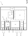
- a shipment warehouse 1 for accepting, temporarily storing and returning shipments 2 is shown.
- the shipments 2 are handed over to a transfer device 3 for acceptance by the shipment warehouse 1 .
- a carrier element 4 in the form of a tray is already kept ready there, onto which the shipment 2 to be accepted is placed via an opening 5 in the shipment warehouse 1 in the transfer device 3 .
- a detection device 6 now detects, for example by means of at least one optical sensor, a height dimension of the shipment 2 and shipment information, for example relating to the addressee or a shipment code.
- the detection device 6 can include at least one, if necessary optical, sensor or scanner.
- the mailing information is used, for example, to ensure that a very specific mailing 2 can always be output from the mailing warehouse 1, and can be stored in a barcode 7 on the mailings 2, for example. It is also conceivable to store the shipment information in a radio frequency identification tag (RFID tag) or a near field communication tag (NFC tag) attached to the shipment. Reading directions for such tags are known and available and can use a local radio network, for example.
- RFID tag radio frequency identification tag
- NFC tag near field communication tag
- the detection of the height dimension is used for the space-saving arrangement of the shipment 2 and the carrier element 4 in at least one shelf system 8 of the shipment warehouse 1.
- the height dimension and the shipment information are recorded and processed by a control device 9 for controlling the shipment warehouse 1. So that the mail items 2 can be placed in the transfer device 3 in any orientation, at least one detection device 6 can be arranged on several sides of the transfer device 3 if necessary.
- the mailing information can also be transmitted via a control panel 10 or electronically. When the shipment information is transmitted electronically, it can be transmitted in the form of a code, for example.
- the transmission can be carried out via a local radio network or a mobile radio network, in particular Global System for Mobile Communication (GSM), Universal Mobile Telecommunications System (UMTS) and/or Long Term Evolution (LTE), Bluetooth or Wireless Local Area Network (WLAN).
- GSM Global System for Mobile Communication
- UMTS Universal Mobile Telecommunications System
- LTE Long Term Evolution
- WLAN Wireless Local Area Network
- At least one width dimension of the carrier elements 4 is reduced as required after the mail items 2 have been accepted by the carrier elements 4 until the corresponding width dimension is adapted to the width dimension of the associated mail item 2 in a predetermined manner.
- the width of the carrier elements 4 corresponds at least essentially to the width of the associated mail items 2 or is only slightly larger, in particular by a certain amount, than the corresponding width of the associated mail items 2.
- the carrier element 4 is gripped by a transport device 11, which in the illustrated and therefore preferred exemplary embodiment is a portal robot that has three movements can perform mutually perpendicular spatial directions.
- the transport device 11 is controlled by the control device 9 which uses the height dimension of the shipment 2 and the width dimension of the shipment 2 to determine a suitable, free storage location for the shipment 2 in the control system 8 of the shipment warehouse 1 .
- the height dimension and the width dimension of the shipment 2 determine how much space must be available in the shelf system 8 for the shipment 2, at least in two spatial directions, in particular horizontally in the width direction and vertically.
- These storage positions are determined by holding elements 12 which define different holding planes 13 arranged vertically one above the other.
- the holding elements 12 are formed by receptacles in the form of grooves that extend at least substantially across the width of the control system 8 .
- the holding elements 12 are preferably aligned horizontally.
- the carrier elements 4 can be positioned along the holding elements 12 in any storage positions. In the vertical direction, however, the carrier elements 4 can only be positioned on the corresponding holding planes 13 in the holding elements 12 . In the case of the shipment store 1 shown and preferred in this respect, this is done by inserting the carrier element 4 into the holding elements 12 in the form of a receptacle or groove.
- the vertical extension of the carrier element 4 is preferably slightly smaller than the vertical extension of the holding elements 12.
- the carrier element 4 is then held in the holding element 12 in a form-fitting manner.
- the transport device 11 can therefore be detached from the carrier element 4 and, for example, move another carrier element 4 to its storage position specified by the control device 9 .
- the control device 9 specifies the respective storage positions in such a way that the available storage space of the shelving system 8 is utilized as well as possible. This means that the control device 9 has information about which carrier element 4 is stored with which shipment 2 at which storage position of the shelf system 8 . If this is known, it is also known which spaces of the shelving system 8 are still free.
- Mail items 2 are output in such a way that the control device 9 is prompted to deliver a specific mail item 2 or to deliver specific items of mail 2 .
- This can be done by entering information linked to the respective shipment 2 , in particular by entering a code, for example on the control panel 10 of the shipment warehouse 1 .
- the information for outputting can also be transmitted electronically, if necessary via a local radio network or a mobile radio network, in particular Global System for Mobile Communication (GSM), Universal Mobile Telecommunications System (UMTS) and/or Long Term Evolution ( LTE), Bluetooth or Wireless Local Area Network (WLAN).
- GSM Global System for Mobile Communication
- UMTS Universal Mobile Telecommunications System
- LTE Long Term Evolution
- WLAN Wireless Local Area Network
- the corresponding shipment 2 can then be received by a collector.
- the carrier element 4 preferably remains in the transfer device 3 for receiving a further shipment 2 or is temporarily stored in the carrier element store 14 until it is required again for storing a shipment 2 in the shipment warehouse 1 .
- several mail items 2 can also be output one after the other without the carrier elements 4 accumulating in the transfer device 3 .
- a carrier element 4 can be removed from the carrier element store 14 and transferred to the transfer device 3 for acceptance, at least for the acceptance of the second and each additional item of mail 2 a shipment 2 are spent.
- control device 9 If the control device 9 recognizes that there are many storage positions in the rack system 8 for receiving only narrow or short shipments 2 due to repeated acceptance and output, the control device 9 can partially rearrange the carrier elements 4 and assign them a different storage position to which the corresponding carrier elements 4 are then consumed by means of the transport device 11. In this way, spaces can be created in the control system 8 for accommodating tall and/or wide mail items 2, for example in the event that such mail items 2 are to be stored.
- the re-sorting described can take place as required, while the mail store 1 is neither requested to issue a mail item 2 nor has a mail item 2 in the transfer device 3 for storage in the mail store 1 .
- transfer devices 3 In order to speed up the acceptance and delivery of mail items 2, instead of a single transfer device 3, several, in particular two, transfer devices can also be provided. Alternatively or additionally, for the same reason, instead of a single transport device 11, several, in particular two, transport devices can be provided, each of which can more preferably be a gantry robot.
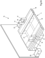
- the adjustment device 15 of the consignment warehouse is off 1 shown, with which the width of the carrier elements 4 are adapted to the width of the mail items 2 received in the transfer device 3 .
- the adjustment device 15 is integrated into the transfer device 3 in the shipment storage facility 1 that is shown and is preferred in this respect.
- the carrier elements 4 have recesses 16 through which the stops 17 of the adjustment device 15 reach and project upwards relative to the carrier element 4 . This is also not necessary if, for example, the stops 17 were provided laterally next to the carrier elements 4 .
- the carrier elements 4 have two carrier element sections 18,19. In principle, however, there could also be more carrier element sections.
- the carrier element sections 18, 19 can be pushed together and pulled apart again, with one carrier element section 18 being partially accommodated in the other carrier element section 19, which is preferred but not mandatory. By pushing the carrier element sections 18, 19 into one another, the width of the carrier element 4 is reduced overall.
- the carrier element 4 is pushed together by means of an electric motor drive 20 which, for example, comprises a spindle drive with a spindle 21 or can be designed as a linear drive.
- an electric motor drive 20 which, for example, comprises a spindle drive with a spindle 21 or can be designed as a linear drive.
- This information is processed by the control device 9 in order to assign the carrier element 4 to a storage position in the shelving system 8 that is wide enough to accommodate the carrier element 4 .
- the control device 9 ensures that the storage position is allocated enough space to accommodate the carrier element 4 and the corresponding shipment 2 therein.
- Distance or proximity sensors could also be attached to the stops 17 in order to end the pushing together of the carrier element 4 before the stops 17 come into contact with the mail items 2 .
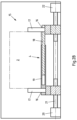
- FIG. 3A-B alternative support elements 23 and alternative shelving system 24 are shown.
- the support elements 23 have two support element sections 25, 26, of which a support element section 28 has two button elements 27 that protrude backwards parallel to the support element 23. These can be hung in a form-fitting manner in corresponding slots 28 of the holding elements 29 which are distributed along the holding elements 29 at regular intervals.
- the button elements 27 must then be lowered into the holding elements 29 and, in order to remove the carrier element 23, first moved upwards again before the carrier element 23 can be pulled horizontally out of the holding element 29. This prevents the carrier elements 23 from accidentally slipping out of the holding elements 29 , but it is accepted that the carrier elements 23 can only be arranged in a specific grid of the shelving system 24 . This is the case with the holding elements 12 in the form of continuous grooves as in the case of the shelving system 8 according to FIG Figures 1A-B not the case.
- the carrier elements 4 can be positioned steplessly next to one another in the groove-shaped holding elements 12 .
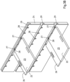
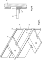
- FIGS. 4A-B alternative support elements 30 and alternative shelving systems 31 are shown.
- the carrier elements 30 have U-shaped retaining strips 32 on the the holding elements 33 of the associated shelving system 31, in the form of continuous ribs, can be attached.
- This configuration of support element 30 and shelf system 31 represents a compromise between the configurations according to FIG Figures 1A-B and 3A-B
- the support elements 30 can be fixed next to one another on a holding element 33 without taking into account a grid, the support elements 30 being simultaneously secured against accidentally slipping out horizontally.
- control system 34 as in the figure 5 shown by way of example, have holding elements 35 in the form of pivoting arms which are swung out into a use position in order to hold a support element and are swung into a non-use position when the holding elements 35 are not required for holding support elements.
Claims (14)
- Entrepôt d'expédition (1) pour la prise en charge, le stockage intermédiaire et la distribution séparément d'une multitude de colis (2) de dimensions différentes, avec un dispositif de transfert (3) pour la prise en charge séparée de colis (2) et pour le transfert des colis (2) à des éléments porteurs séparés (4, 23, 30), notamment des plateaux, des entrepôts d'expédition, avec un dispositif de détection (6) pour détecter les dimensions en hauteur des colis (2), avec un système d'étagères (8, 24, 31, 34) comportant des éléments de retenue (12, 29, 33, 35) agencés superposés dans le sens vertical et définissant des plans de retenue (13), les éléments de retenue (12, 29, 33, 35) et les éléments porteurs (4, 23, 30) étant conçus de manière correspondante de telle sorte que, d'une part, sur au moins deux plans de retenue (13) adjacents, deux éléments porteurs (4, 23, 30) portant chacun un colis (2) peuvent être maintenus superposés dans le sens vertical et en ce que, d'autre part, sur au moins un plan de retenue (13), un élément porteur (4, 23, 30) avec un colis (2), qui est plus haut que la distance verticale au plan de retenue (13) immédiatement supérieur, peut être retenu, au moins un dispositif de commande (9) étant prévu pour attribuer les éléments porteurs (4, 23, 30) portant les colis (2), superposés dans le sens vertical, à différents éléments de retenue (12, 29, 33, 35) et/ou positions de stockage en fonction des dimensions en hauteur détectées des colis (2) portés par les éléments porteurs (4, 23, 30), caractérisé en ce que l'on prévoit un dispositif d'adaptation (15) pour adapter une dimension en largeur et/ou en longueur des éléments porteurs (4, 23, 30) à au moins une dimension en largeur et/ou en longueur des colis correspondants (2).
- Entrepôt d'expédition selon la revendication 1, caractérisé en ce que la dimension en largeur et/ou en longueur des éléments porteurs (4, 23, 30) peuvent être réglées, l'une par rapport à l'autre, par l'extraction et/ou l'introduction de sections d'éléments porteurs (18, 19, 25, 26) et en ce que, de préférence, le dispositif d'adaptation (15) et/ou les éléments porteurs (4, 23, 30) et/ou le dispositif d'adaptation (15) présentent au moins une butée (17) en appui contre le colis correspondant (2) lors de l'introduction de sections d'éléments porteurs (18, 19, 25, 26) et de moyens d'arrêt (22) pour terminer l'introduction ultérieure des sections des éléments porteurs (18, 19, 25, 26).
- Entrepôt d'expédition selon la revendication 1 ou 2, caractérisé en ce que le dispositif de commande (9) est conçu pour attribuer des éléments porteurs (4, 23, 30) portant des colis (2) à des positions de stockage, notamment à un plan de retenue commun (13), côte à côte, en fonction de la dimension en largeur et/ou en longueur des éléments porteurs (4, 23, 30) et/ou des colis (2) et/ou en ce que le dispositif de commande est conçu pour exploiter plus efficacement l'espace de stockage en déplaçant au moins un élément porteur (4, 23, 30) portant un colis (2) d'une position de stockage à une autre position de stockage et/ou en ce que le dispositif de commande (9) est conçu pour associer les informations d'expédition, les dimensions en hauteur, la dimension en largeur et/ou la dimension en longueur des colis (2) aux éléments porteurs (4, 23, 30) associés aux colis (2) et/ou aux positions de stockage associées aux colis et/ou aux éléments porteurs (4, 23, 30).
- Entrepôt d'expédition selon l'une des revendications 1 à 3, caractérisé en ce que le dispositif de détection (6) présente un scanner de dimension pour détecter les dimensions en hauteur, la dimension en largeur et/ou la dimension en longueur des colis (2) et/ou en ce que le dispositif de détection (6) présente un scanner, notamment un lecteur de code-barres, un lecteur RFID et/ou un lecteur NFC, pour détecter les informations d'expédition, de préférence concernant le destinataire, l'utilisateur, un numéro de suivi, de préférence individuel, la dimension en hauteur, en largeur et/ou en longueur.
- Entrepôt d'expédition selon l'une des revendications 1 à 4, caractérisé en ce que l'on prévoit un dispositif de transport (11) pour le transport des éléments porteurs (4, 23, 30) portant des colis (2) du dispositif de transfert (3) à des positions de stockage et/ou inversement et/ou le dispositif de transport (11) présente un robot portique pour le réglage des éléments porteurs (4, 23, 30), au moins dans deux directions spatiales perpendiculaires entre elles, et en ce que, de préférence, le robot portique est conçu pour transférer les éléments porteurs (4, 23, 30) aux éléments de retenue (12, 29, 33, 35) et/ou pour enlever les éléments porteurs (4, 23, 30) des éléments de retenue (12, 29, 33, 35).
- Entrepôt d'expédition selon l'une des revendications 1 à 5, caractérisé en ce que les éléments de retenue (35) définissant les plans de retenue présentent des bras pivotants pour le pivotement vers l'extérieur, dans une position d'utilisation, et pour le pivotement vers l'intérieur, dans une position de non d'utilisation, et/ou en ce que les éléments de retenue définissant les plans de retenue peuvent être déplacés entre plusieurs positions d'utilisation et/ou entre au moins une position d'utilisation et au moins une position de non-utilisation et/ou en ce que les éléments de retenue définissant les plans de retenue peuvent être démontés.
- Entrepôt d'expédition selon l'une des revendications 1 à 6, caractérisé en ce que les éléments de retenue (12, 29, 33) définissant les plans de retenue (13) sont conçus par des logements, notamment sous forme de gorges, pour loger, notamment par complémentarité de forme, les éléments de retenue (4, 23, 30) portant des colis (2), et en ce que, de préférence, au moins un plan de retenue (13), de préférence tous les plans de retenue (13), sont définis par un seul logement continue et/ou une seule gorge continue.
- Entrepôt d'expédition selon l'une des revendications 1 à 7, caractérisé en ce que le dispositif de transfert (3) est conçu pour la distribution séparée de colis (2) stockés avec des éléments porteurs (4, 23, 30) dans des positions de stockage et/ou en ce qu'il comporte une unité de stockage d'éléments porteurs (14) pour l'entreposage intermédiaire d'éléments porteurs (4, 23, 30) non utilisés.
- Procédé pour l'exploitation d'un entrepôt d'expédition (1) pour la prise en charge, le stockage intermédiaire et la distribution séparément d'une multitude de colis (2) de dimensions différentes, de préférence en utilisant un entrepôt d'expédition selon l'une des revendications 1 à 8,- dans lequel les colis (2) sont pris en charge, séparément, par un dispositif de transfert (3) et transférés à des éléments porteurs (4, 23, 30) séparés, notamment à des plateaux,- dans lequel les dimensions en hauteur des colis (2) sont détectées à l'aide d'un dispositif de détection (6),- dans lequel les éléments porteurs (4, 23, 30) portant les colis (2) sont attribués, à l'aide d'un dispositif de commande (9), en fonction des dimensions en hauteur détectées, à des éléments de retenue d'un système d'étagères définissant des plans de retenue (13), prévus superposés dans le sens vertical, de telle sorte que, sur au moins certains plans de retenue, les éléments porteurs (4, 23, 30) avec un colis (2), qui est plus hauts que la distance verticale par rapport au plan de retenue (13) immédiatement supérieur, soient agencés, superposés dans le sens vertical, caractérisé en ce que- une dimension en largeur et/ou en longueur des éléments porteurs (4, 23, 30) dans un dispositif d'adaptation (15) est adaptée à une dimension en largeur et/ou en longueur des colis (2) associés.
- Procédé selon la revendication 9,- dans lequel la dimension en largeur et/ou en longueur des éléments porteurs (4, 23, 30) sont réglées, l'une par rapport à l'autre, par extraction et/ou introduction de sections d'éléments porteurs (18, 19, 25, 26) et- dans lequel, de préférence, les sections des éléments porteurs (18, 19, 25, 26) sont introduites jusqu'à ce qu'au moins une butée (17) du dispositif d'adaptation (15) et/ou des éléments porteurs (4, 23, 30) soit en appui contre le colis (2) correspondant et qu'un moyen d'arrêt (22) termine l'introduction ultérieure des sections des éléments porteurs (18, 19, 25, 26).
- Procédé selon la revendication 9 ou 10,- dans lequel les éléments porteurs (4, 23, 30) portant les colis (2) sont attribués côte à côte, en fonction de la dimension en largeur et/ou en longueur des éléments porteurs (4, 23, 30) et/ou des colis (2), par le dispositif de commande (9) à des positions de stockage, notamment à un niveau de retenue (13) commun et/ou- dans lequel au moins des éléments porteurs (4, 23, 30) portant les colis (2) individuels sont triés par le dispositif de commande (9) en fonction des positions de stockage respectives afin d'exploiter plus efficacement l'espace de stockage disponible et/ou- dans lequel les informations d'expédition, les dimensions en hauteur, la dimension en largeur et/ou la dimension en longueur des colis (2) sont attribuées par le dispositif de commande (9) aux éléments porteurs (4, 23, 30) associés aux colis (2) et/ou aux positions de stockage associées aux colis (2) et/ou aux éléments porteurs (4, 23, 30).
- Procédé selon l'une des revendications 9 à 11,- dans lequel les dimensions en hauteur, la dimension en largeur et/ou la dimension en longueur des colis (2) transférés à l'entrepôt d'expédition (1) sont détectées à l'aide d'un scanner de dimension d'un dispositif de détection et/ou- dans lequel les informations d'expédition concernant, de préférence, le destinataire, l'utilisateur et/ou un numéro de suivi, de préférence individuel, les dimensions en hauteur, la dimension en largeur et/ou la dimension en longueur des colis (2) transférés à l'entrepôt d'expédition (1) sont détectées à l'aide d'un scanner, notamment un lecteur de code-barres, un lecteur RFID et/ou un lecteur NFC, du dispositif de détection.
- Procédé selon l'une des revendications 9 à 12,- dans lequel les éléments porteurs (4, 23, 30) présentant les colis (2) sont transportés avec un dispositif de transport (11) du dispositif de transfert (3) vers des positions de stockage et/ou inversement et- dans lequel, de préférence, les éléments porteurs (4, 23, 30) sont déplacés par un robot portique du dispositif de transport (11) au moins dans deux directions spatiales perpendiculaires entre elles et/ou sont transférés aux éléments de retenue (12, 29, 33, 35) conformément à la position de stockage prédéterminée et/ou prélevés par les éléments de retenue (12, 29, 33, 35) correspondants pour la distribution des colis (2).
- Procédé selon l'une des revendications 9 à 13,- dans lequel les éléments porteurs (4, 23, 30) portant les colis (2) sont introduits, au moins par sections, dans les éléments de retenue (12, 29, 33, 35) définissant les plans de retenue (13) sous forme de logements, notamment sous forme de gorges, et, de préférence retenus par complémentarité de forme, et/ou- dans lequel les colis (2) stockés avec les éléments porteurs (4, 23, 30) dans des positions de stockage sont distribués séparément à l'aide du dispositif de transfert (3) et/ou- dans lequel les éléments porteurs (4, 23, 30) non utilisés sont entreposés, de manière intermédiaire, dans une unité de stockage d'éléments porteurs (14) jusqu'à leur réutilisation.
Applications Claiming Priority (1)
| Application Number | Priority Date | Filing Date | Title |
|---|---|---|---|
| DE102018100448.6A DE102018100448A1 (de) | 2018-01-10 | 2018-01-10 | Sendungslager und Verfahren zum Übernehmen, Zwischenlagern und Ausgeben von Sendungen |
Publications (3)
| Publication Number | Publication Date |
|---|---|
| EP3511268A1 EP3511268A1 (fr) | 2019-07-17 |
| EP3511268B1 true EP3511268B1 (fr) | 2023-08-09 |
| EP3511268C0 EP3511268C0 (fr) | 2023-08-09 |
Family
ID=65010676
Family Applications (1)
| Application Number | Title | Priority Date | Filing Date |
|---|---|---|---|
| EP19150969.4A Active EP3511268B1 (fr) | 2018-01-10 | 2019-01-09 | Stockage d'envois et procédé de réception, de stockage intermédiaire et de distribution d'envois |
Country Status (4)
| Country | Link |
|---|---|
| US (1) | US10974915B2 (fr) |
| EP (1) | EP3511268B1 (fr) |
| CN (1) | CN110015528B (fr) |
| DE (1) | DE102018100448A1 (fr) |
Families Citing this family (7)
| Publication number | Priority date | Publication date | Assignee | Title |
|---|---|---|---|---|
| US11167925B2 (en) | 2019-09-11 | 2021-11-09 | Ebay Inc. | Systems and methods for automatically reconfiguring a building structure |
| US20230031912A1 (en) * | 2019-12-24 | 2023-02-02 | Trakkit Pty Ltd | An automated mobile inventory system |
| CN111674817B (zh) * | 2020-06-12 | 2021-12-17 | 深圳市海柔创新科技有限公司 | 仓储机器人的控制方法、装置、设备及可读存储介质 |
| CN112884996A (zh) * | 2021-01-13 | 2021-06-01 | 李琳琳 | 一种采用门铃收快递的方法、系统及门铃 |
| DE102021102487A1 (de) * | 2021-02-03 | 2022-08-04 | Aixinno Limited | Verfahren zum Handhaben biologischer Zellkulturen |
| CN112896894B (zh) * | 2021-02-09 | 2022-10-21 | 深圳市海柔创新科技有限公司 | 货物运输方法、装置、流利货架、仓储系统及存储介质 |
| DE102021113522A1 (de) | 2021-05-26 | 2022-12-01 | BJK MUC UG (haftungsbeschränkt) | Lagereinrichtung und Verfahren zum Ein-, Aus und/oder Umlagern von Gegenständen, Verfahren, Steuer- und/oder Regeleinrichtung sowie Lagersystem |
Family Cites Families (15)
| Publication number | Priority date | Publication date | Assignee | Title |
|---|---|---|---|---|
| JPH02158501A (ja) * | 1988-12-08 | 1990-06-19 | Toshiba Corp | 自動格納倉庫 |
| US5072573A (en) * | 1990-01-12 | 1991-12-17 | Tisma Machine Corporation | Apparatus with adjustable width trays for automatic packaging machines |
| IT1237950B (it) * | 1990-01-15 | 1993-06-19 | Fata Automation | Magazzino automatico adattabile |
| DE29900899U1 (de) * | 1999-01-21 | 2000-06-29 | Kuka Schweissanlagen Gmbh | Lagersystem für ein Verteilzentrum von Waren |
| EP1273531A1 (fr) * | 2001-07-02 | 2003-01-08 | Crisplant A/S | Un systême de stockage pour stocker des articles à distribuer |
| DE10349469A1 (de) * | 2003-10-23 | 2005-06-02 | Fraunhofer-Gesellschaft zur Förderung der angewandten Forschung e.V. | Verfahren zur Handhabung und Lagerung von Stückgütern |
| US9321591B2 (en) * | 2009-04-10 | 2016-04-26 | Symbotic, LLC | Autonomous transports for storage and retrieval systems |
| WO2012017929A1 (fr) * | 2010-08-04 | 2012-02-09 | 塩島梱包株式会社 | Palette à dimensions variables |
| DE102010042617A1 (de) * | 2010-10-19 | 2012-04-19 | Hänel GmbH & Co. KG | Lagereinrichtung und Verfahren zum Einlagern |
| CN102092505A (zh) * | 2011-03-17 | 2011-06-15 | 芜湖安得物流股份有限公司 | 可伸缩组合托盘 |
| PL2502842T3 (pl) * | 2011-03-21 | 2016-08-31 | Traeab Saevsjoestroem Trae Ab | Regulowany system paletowy |
| JP2015042563A (ja) * | 2013-07-22 | 2015-03-05 | 塩島梱包株式会社 | 寸法可変パレット |
| EP2876614A1 (fr) * | 2013-11-25 | 2015-05-27 | Wincor Nixdorf International GmbH | Station de paquets entièrement automatique |
| CN104670626B (zh) * | 2015-03-09 | 2017-11-07 | 京东方科技集团股份有限公司 | 一种托盘 |
| ES2910248T3 (es) * | 2015-09-12 | 2022-05-12 | Cleveron As | Terminal de paquetería y un método para optimizar la capacidad de paquetes en dicha terminal |
-
2018
- 2018-01-10 DE DE102018100448.6A patent/DE102018100448A1/de active Pending
-
2019
- 2019-01-09 CN CN201910019421.1A patent/CN110015528B/zh active Active
- 2019-01-09 EP EP19150969.4A patent/EP3511268B1/fr active Active
- 2019-01-10 US US16/245,015 patent/US10974915B2/en active Active
Also Published As
| Publication number | Publication date |
|---|---|
| CN110015528A (zh) | 2019-07-16 |
| CN110015528B (zh) | 2021-02-12 |
| EP3511268C0 (fr) | 2023-08-09 |
| US10974915B2 (en) | 2021-04-13 |
| DE102018100448A1 (de) | 2019-07-11 |
| US20190210818A1 (en) | 2019-07-11 |
| EP3511268A1 (fr) | 2019-07-17 |
Similar Documents
| Publication | Publication Date | Title |
|---|---|---|
| EP3511268B1 (fr) | Stockage d'envois et procédé de réception, de stockage intermédiaire et de distribution d'envois | |
| EP3228496B1 (fr) | Véhicule de distribution et procédé de livraison d'envois dans différents endroits suivant un itinéraire de distribution | |
| EP3328759B1 (fr) | Procédé et système de livraison de marchandises dans des récipients de livraison | |
| DE60106989T2 (de) | Vorrichtung und Verfahren für automatisiertes Warenlager | |
| EP2421774B1 (fr) | Système de stockage et de préparation et procédé permettant de faire fonctionner ce dernier en mode de traitement par lots | |
| EP2297005B2 (fr) | Système de stockage et procédé pour le faire fonctionner | |
| DE4318341B4 (de) | Verfahren zur Lagerung von Apotheken-Artikeln und Vorrichtung zur Durchführung eines solchen Verfahrens | |
| AT516875B1 (de) | Verfahren zum Einlagern von Stückgütern in ein Lagerregal und Lagersystem | |
| EP2186754B1 (fr) | Installation de préparation et son procédé de fonctionnement avec un chariot de préparation | |
| EP2287092A1 (fr) | Système de commissionnement semi-automatique et/ou totalement automatique | |
| DE10225332A1 (de) | Einlagerungspuffer und Erfahren zum Einlagern von Stückgütern für ein automatisiertes Stückgutlager | |
| EP1620332B1 (fr) | Dispositif et procede d'exploitation d'un entrepot | |
| EP3509969B1 (fr) | Système de stockage automatisé servant au transport de supports de charge tournés dans la direction de déplacement | |
| EP1818283B1 (fr) | Procédé de stockage de marchandises au détail dans un entrepôt de marchandises au détail automatisé | |
| AT520860B1 (de) | Kommissioniersystem zum Lagern und Kommissionieren von Packeinheiten sowie Ladungsträger für die Packeinheiten | |
| EP2275363B1 (fr) | Procédé et dispositif de tri automatique de différents récipients vides réutilisables pour boissons | |
| EP0986508B1 (fr) | Systeme de preparation des commandes comportant une machine automatique a vitesse elevee et une unite de commande de rayonnages | |
| DE102013014334A1 (de) | Lagerautomat | |
| DE10016693B4 (de) | Platinen-Stapel- und Verteilanlage | |
| AT511598B1 (de) | Automatisiertes warenumschlaglager | |
| EP1035046B1 (fr) | Méthode pour faire fonctionner un magasin de stockage automatique | |
| DE4420357A1 (de) | Magazinier-System | |
| EP0198402A2 (fr) | Magasin avec stockage et déstockage automatiques des marchandises | |
| DE102009052345A1 (de) | Automatisierte Kommissioniervorrichtung und Verfahren zum automatisierten Kommissionieren von Büchern, Medien, Prospekten und ähnlichen Gegenständen | |
| DE3203757A1 (de) | Vorrichtung zum zwischenstapeln von gegenstaenden |
Legal Events
| Date | Code | Title | Description |
|---|---|---|---|
| PUAI | Public reference made under article 153(3) epc to a published international application that has entered the european phase |
Free format text: ORIGINAL CODE: 0009012 |
|
| STAA | Information on the status of an ep patent application or granted ep patent |
Free format text: STATUS: THE APPLICATION HAS BEEN PUBLISHED |
|
| AK | Designated contracting states |
Kind code of ref document: A1 Designated state(s): AL AT BE BG CH CY CZ DE DK EE ES FI FR GB GR HR HU IE IS IT LI LT LU LV MC MK MT NL NO PL PT RO RS SE SI SK SM TR |
|
| AX | Request for extension of the european patent |
Extension state: BA ME |
|
| STAA | Information on the status of an ep patent application or granted ep patent |
Free format text: STATUS: REQUEST FOR EXAMINATION WAS MADE |
|
| 17P | Request for examination filed |
Effective date: 20200117 |
|
| RBV | Designated contracting states (corrected) |
Designated state(s): AL AT BE BG CH CY CZ DE DK EE ES FI FR GB GR HR HU IE IS IT LI LT LU LV MC MK MT NL NO PL PT RO RS SE SI SK SM TR |
|
| STAA | Information on the status of an ep patent application or granted ep patent |
Free format text: STATUS: EXAMINATION IS IN PROGRESS |
|
| 17Q | First examination report despatched |
Effective date: 20220408 |
|
| GRAP | Despatch of communication of intention to grant a patent |
Free format text: ORIGINAL CODE: EPIDOSNIGR1 |
|
| STAA | Information on the status of an ep patent application or granted ep patent |
Free format text: STATUS: GRANT OF PATENT IS INTENDED |
|
| RIC1 | Information provided on ipc code assigned before grant |
Ipc: G07F 7/00 20060101ALI20230201BHEP Ipc: G06Q 10/08 20120101ALI20230201BHEP Ipc: G07F 17/12 20060101ALI20230201BHEP Ipc: B65G 1/04 20060101AFI20230201BHEP |
|
| INTG | Intention to grant announced |
Effective date: 20230227 |
|
| GRAS | Grant fee paid |
Free format text: ORIGINAL CODE: EPIDOSNIGR3 |
|
| GRAA | (expected) grant |
Free format text: ORIGINAL CODE: 0009210 |
|
| STAA | Information on the status of an ep patent application or granted ep patent |
Free format text: STATUS: THE PATENT HAS BEEN GRANTED |
|
| AK | Designated contracting states |
Kind code of ref document: B1 Designated state(s): AL AT BE BG CH CY CZ DE DK EE ES FI FR GB GR HR HU IE IS IT LI LT LU LV MC MK MT NL NO PL PT RO RS SE SI SK SM TR |
|
| REG | Reference to a national code |
Ref country code: GB Ref legal event code: FG4D Free format text: NOT ENGLISH |
|
| REG | Reference to a national code |
Ref country code: CH Ref legal event code: EP |
|
| REG | Reference to a national code |
Ref country code: DE Ref legal event code: R096 Ref document number: 502019008821 Country of ref document: DE |
|
| REG | Reference to a national code |
Ref country code: IE Ref legal event code: FG4D Free format text: LANGUAGE OF EP DOCUMENT: GERMAN |
|
| U01 | Request for unitary effect filed |
Effective date: 20230906 |
|
| U07 | Unitary effect registered |
Designated state(s): AT BE BG DE DK EE FI FR IT LT LU LV MT NL PT SE SI Effective date: 20230914 |
|
| PG25 | Lapsed in a contracting state [announced via postgrant information from national office to epo] |
Ref country code: GR Free format text: LAPSE BECAUSE OF FAILURE TO SUBMIT A TRANSLATION OF THE DESCRIPTION OR TO PAY THE FEE WITHIN THE PRESCRIBED TIME-LIMIT Effective date: 20231110 |
|
| PG25 | Lapsed in a contracting state [announced via postgrant information from national office to epo] |
Ref country code: IS Free format text: LAPSE BECAUSE OF FAILURE TO SUBMIT A TRANSLATION OF THE DESCRIPTION OR TO PAY THE FEE WITHIN THE PRESCRIBED TIME-LIMIT Effective date: 20231209 |
|
| PG25 | Lapsed in a contracting state [announced via postgrant information from national office to epo] |
Ref country code: RS Free format text: LAPSE BECAUSE OF FAILURE TO SUBMIT A TRANSLATION OF THE DESCRIPTION OR TO PAY THE FEE WITHIN THE PRESCRIBED TIME-LIMIT Effective date: 20230809 Ref country code: NO Free format text: LAPSE BECAUSE OF FAILURE TO SUBMIT A TRANSLATION OF THE DESCRIPTION OR TO PAY THE FEE WITHIN THE PRESCRIBED TIME-LIMIT Effective date: 20231109 Ref country code: IS Free format text: LAPSE BECAUSE OF FAILURE TO SUBMIT A TRANSLATION OF THE DESCRIPTION OR TO PAY THE FEE WITHIN THE PRESCRIBED TIME-LIMIT Effective date: 20231209 Ref country code: HR Free format text: LAPSE BECAUSE OF FAILURE TO SUBMIT A TRANSLATION OF THE DESCRIPTION OR TO PAY THE FEE WITHIN THE PRESCRIBED TIME-LIMIT Effective date: 20230809 Ref country code: GR Free format text: LAPSE BECAUSE OF FAILURE TO SUBMIT A TRANSLATION OF THE DESCRIPTION OR TO PAY THE FEE WITHIN THE PRESCRIBED TIME-LIMIT Effective date: 20231110 |
|
| U20 | Renewal fee paid [unitary effect] |
Year of fee payment: 6 Effective date: 20240123 |
|
| PG25 | Lapsed in a contracting state [announced via postgrant information from national office to epo] |
Ref country code: PL Free format text: LAPSE BECAUSE OF FAILURE TO SUBMIT A TRANSLATION OF THE DESCRIPTION OR TO PAY THE FEE WITHIN THE PRESCRIBED TIME-LIMIT Effective date: 20230809 |
|
| PG25 | Lapsed in a contracting state [announced via postgrant information from national office to epo] |
Ref country code: ES Free format text: LAPSE BECAUSE OF FAILURE TO SUBMIT A TRANSLATION OF THE DESCRIPTION OR TO PAY THE FEE WITHIN THE PRESCRIBED TIME-LIMIT Effective date: 20230809 |
|
| PG25 | Lapsed in a contracting state [announced via postgrant information from national office to epo] |
Ref country code: SM Free format text: LAPSE BECAUSE OF FAILURE TO SUBMIT A TRANSLATION OF THE DESCRIPTION OR TO PAY THE FEE WITHIN THE PRESCRIBED TIME-LIMIT Effective date: 20230809 Ref country code: RO Free format text: LAPSE BECAUSE OF FAILURE TO SUBMIT A TRANSLATION OF THE DESCRIPTION OR TO PAY THE FEE WITHIN THE PRESCRIBED TIME-LIMIT Effective date: 20230809 Ref country code: ES Free format text: LAPSE BECAUSE OF FAILURE TO SUBMIT A TRANSLATION OF THE DESCRIPTION OR TO PAY THE FEE WITHIN THE PRESCRIBED TIME-LIMIT Effective date: 20230809 Ref country code: CZ Free format text: LAPSE BECAUSE OF FAILURE TO SUBMIT A TRANSLATION OF THE DESCRIPTION OR TO PAY THE FEE WITHIN THE PRESCRIBED TIME-LIMIT Effective date: 20230809 Ref country code: SK Free format text: LAPSE BECAUSE OF FAILURE TO SUBMIT A TRANSLATION OF THE DESCRIPTION OR TO PAY THE FEE WITHIN THE PRESCRIBED TIME-LIMIT Effective date: 20230809 |
|
| PGFP | Annual fee paid to national office [announced via postgrant information from national office to epo] |
Ref country code: GB Payment date: 20240123 Year of fee payment: 6 |