EP3509782B1 - Werkzeugschaft mit kopfstützfläche mit zentraler aussparung, die mit elastisch verschiebbaren auflageabschnitten versehen ist - Google Patents
Werkzeugschaft mit kopfstützfläche mit zentraler aussparung, die mit elastisch verschiebbaren auflageabschnitten versehen ist Download PDFInfo
- Publication number
- EP3509782B1 EP3509782B1 EP17764910.0A EP17764910A EP3509782B1 EP 3509782 B1 EP3509782 B1 EP 3509782B1 EP 17764910 A EP17764910 A EP 17764910A EP 3509782 B1 EP3509782 B1 EP 3509782B1
- Authority
- EP
- European Patent Office
- Prior art keywords
- central recess
- rotation
- longitudinal axis
- abutment
- tool shank
- Prior art date
- Legal status (The legal status is an assumption and is not a legal conclusion. Google has not performed a legal analysis and makes no representation as to the accuracy of the status listed.)
- Active
Links
- 238000005520 cutting process Methods 0.000 claims description 42
- 230000000717 retained effect Effects 0.000 claims description 8
- 238000000034 method Methods 0.000 claims description 4
- 230000002093 peripheral effect Effects 0.000 description 4
- 230000005540 biological transmission Effects 0.000 description 3
- 238000005553 drilling Methods 0.000 description 2
- 229910001315 Tool steel Inorganic materials 0.000 description 1
- 230000004075 alteration Effects 0.000 description 1
- 229910052751 metal Inorganic materials 0.000 description 1
- 239000002184 metal Substances 0.000 description 1
- 238000012986 modification Methods 0.000 description 1
- 230000004048 modification Effects 0.000 description 1
- 238000003825 pressing Methods 0.000 description 1
- 238000005245 sintering Methods 0.000 description 1
- 230000007704 transition Effects 0.000 description 1
- UONOETXJSWQNOL-UHFFFAOYSA-N tungsten carbide Chemical compound [W+]#[C-] UONOETXJSWQNOL-UHFFFAOYSA-N 0.000 description 1
Images


Classifications
-
- B—PERFORMING OPERATIONS; TRANSPORTING
- B23—MACHINE TOOLS; METAL-WORKING NOT OTHERWISE PROVIDED FOR
- B23B—TURNING; BORING
- B23B51/00—Tools for drilling machines
- B23B51/02—Twist drills
-
- B—PERFORMING OPERATIONS; TRANSPORTING
- B23—MACHINE TOOLS; METAL-WORKING NOT OTHERWISE PROVIDED FOR
- B23B—TURNING; BORING
- B23B2231/00—Details of chucks, toolholder shanks or tool shanks
- B23B2231/02—Features of shanks of tools not relating to the operation performed by the tool
- B23B2231/0204—Connection of shanks to working elements of tools
-
- B—PERFORMING OPERATIONS; TRANSPORTING
- B23—MACHINE TOOLS; METAL-WORKING NOT OTHERWISE PROVIDED FOR
- B23B—TURNING; BORING
- B23B2251/00—Details of tools for drilling machines
- B23B2251/02—Connections between shanks and removable cutting heads
-
- B—PERFORMING OPERATIONS; TRANSPORTING
- B23—MACHINE TOOLS; METAL-WORKING NOT OTHERWISE PROVIDED FOR
- B23B—TURNING; BORING
- B23B2251/00—Details of tools for drilling machines
- B23B2251/40—Flutes, i.e. chip conveying grooves
-
- B—PERFORMING OPERATIONS; TRANSPORTING
- B23—MACHINE TOOLS; METAL-WORKING NOT OTHERWISE PROVIDED FOR
- B23B—TURNING; BORING
- B23B2251/00—Details of tools for drilling machines
- B23B2251/50—Drilling tools comprising cutting inserts
Definitions
- the present invention relates to a rotary cutting tool and a tool shank having a head receiving pocket with resiliently displaceable abutment portions, for use in metal cutting processes in general, and for drilling operations in particular.
- tool shanks having head receiving pockets with 'circumferentially open' central recesses and resiliently displaceable abutment portions.
- US 7,360,974 discloses a rotary cutting tool having a tool shank and a replaceable cutting insert.
- the tool shank includes two longitudinally extending chip flutes and a location opening at the tip of the shank which is open to the chip flutes.
- the location opening has a circular cross-section.
- the cutting insert includes a fastening pin having a slightly elliptical cross-section which is inserted into the location opening and rotated into a braced position.
- US 7,467,915 discloses a rotary cutting tool having a tool shank and a replaceable cutting head which is installed on and engages a head receiving pocket of the tool shank.
- the cutting head has a shank connection portion with a dovetail member.
- the head receiving pocket includes two generally symmetrical castellated wall sections projecting upwardly from a central floor portion.
- the castellated wall sections include internally facing frustoconical surfaces, and when the dovetail member is rotated into an interlocked position with respect to the head receiving pocket, the dovetail member engages the internally facing frustoconical surfaces.
- US 2009/116920 A1 discloses a tool shank according to the preamble of claim 1.
- a tool shank having a longitudinal axis of rotation establishing a forward-to-rearward direction and comprising: a head receiving pocket at a forward end, and a plurality of chip flutes extending in the rearward direction therefrom along the longitudinal axis of rotation,
- a rotary cutting tool comprising a tool shank of the sort described above, and a cutting head releasably mounted in the head receiving pocket thereof, the cutting head comprising: a cutting portion and a mounting portion,
- the present invention relates to a tool shank 20 having a longitudinal axis of rotation A1 establishing a forward direction D F to rearward direction D R .
- the tool shank 20 has a head receiving pocket 22 at a forward end 24, and a plurality of chip flutes 26 extending in the rearward direction D R therefrom along the longitudinal axis of rotation A1 .
- the plurality of chip flutes 26 may be formed in a cylindrical shank peripheral surface 28 of the tool shank 20.
- the tool shank 20 may have three chip flutes 26.
- the tool shank 20 may preferably be manufactured from tool steel.
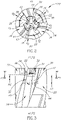
- the head receiving pocket 22 has a support surface 30 transverse to the longitudinal axis of rotation A1 .
- a central recess 32 is formed in the support surface 30 and extends in the rearward direction D R therefrom, along the longitudinal axis of rotation A1 .
- the support surface 30 may be radially spaced apart from the shank peripheral surface 28 of the tool shank 20 and located in a central area of the pocket 22, and thus may be considered to be a "central" support surface 30.
- the central recess 32 does not intersect any of the plurality of chip flutes 26.
- the head receiving pocket 22 may be devoid of a passage communicating the central recess 32 with any of the plurality of chip flutes 26 .
- the support surface 30 may be planar and perpendicular to the longitudinal axis of rotation A1.
- a plurality of drive members 34 may protrude forwardly from the support surface 30, and each drive member 34 may include a drive surface 36 facing in a rotation direction R about the longitudinal axis of rotation A1 .
- the central recess 32 may be non-circular, and therefore may have a non-circular cross-section.
- the central recess 32 may exhibit rotational symmetry about the longitudinal axis of rotation A1 .
- the central recess 32 may exhibit mirror symmetry about a second plane P2 containing the longitudinal axis of rotation A1 .
- the central recess 32 has a plurality of resiliently displaceable abutment portions 38 circumferentially alternating with and spaced apart by a plurality of intermediate portions 40.
- the plurality of abutment portions 38 may be resiliently displaceable in a radially outward direction Do.
- the plurality of abutment portions 38 may be equal in number to the plurality of intermediate portions 40.
- the plurality of abutment portions 38 may be equal in number to the plurality of chip flutes 26.
- each abutment portion 38 has a radially inward facing abutment surface 42
- each intermediate portion 40 has an intermediate surface 44 intersecting two circumferentially adjacent abutment surfaces 42.
- Each intermediate surface 44 extends radially outward of the two adjacent abutment surfaces 42.
- the head receiving pocket 22 has a 'circumferentially confined' central recess 32, which improves the resilience of the plurality of abutment portions 38 and extends the useful life of the tool shank 20.
- the plurality of intermediate surfaces 44 may extend along the entire longitudinal extent of the plurality of abutment surfaces 42.
- the plurality of intermediate surfaces 44 may extend to a first recess depth H1 rearward of the support surface 30 to a central recess floor 45, and the plurality of abutment surfaces 42 may extend to a second recess depth H2 rearward of the support surface 30 and be longitudinally spaced apart from the central recess floor 45.
- a ratio of the first recess depth H1 to the second recess depth H2 may have a range of between 1.3 and 2.5 (1.3 ⁇ H1/H2 ⁇ 2.5). This provides the plurality of abutment portions 38 with an optimum level of resilience in the region of the abutment surfaces 42.
- the plurality of intermediate surfaces 44 may intersect the support surface 30.
- each abutment portion 38 may include an abutment chamfer 46 between its abutment surface 42 and the support surface 30.
- the plurality of abutment surfaces 42 may diverge in the rearward direction D R .
- two transition edges 48 may be formed at the intersection of each intermediate surface 44 and its two circumferentially adjacent abutment surfaces 42.
- the entire central recess 32 (whose outline is indicated by the broken lines) may be hidden from view, with no portion of the abutment surfaces 42 and the intermediate surfaces 44 being visible.
- the central recess 32 can be considered to be a "sunken" central recess 32 which is formed in the support surface 30.
- each abutment surface 42 has a first circumferential angular extent E1 and each intermediate surface 44 has a second circumferential angular extent E2.
- the combined circumferential angular extent of the plurality of abutment surfaces 42 and the plurality of intermediate surfaces 44 may be equal to 360°.
- the second circumferential angular extent E2 may be greater than the first circumferential angular extent E1 .
- the imaginary first circle C1 may contact the plurality of abutment surfaces 42.
- the plurality of intermediate surfaces 44 may be located outside the imaginary first circle C1 .
- an imaginary second circle C2 coaxial with the longitudinal axis of rotation A1 is tangent to the plurality of chip flutes 26 at a plurality of first flute points N F 1 .
- a third plane P3 containing the longitudinal axis of rotation A1 and at least one of the first flute points N F 1 may intersect at least one of the abutment surfaces 42.
- the imaginary first circle C1 has a first diameter D1
- the imaginary second circle C2 has a second diameter D2
- first diameter D1 may be greater than half the second diameter D2.
- first diameter D1 of the imaginary first circle C1 is measured in the absence of radially outward forces Fo being applied to the plurality of abutment surfaces 42.
- the imaginary first circle C1 has a first loaded diameter D L 1 .
- the first diameter D1 may be less than the first loaded diameter D L 1 .
- a radial axis A2 is formed at the intersection of the first and third planes P1, P3.
- each first flute point N F 1 may be located a minimum first distance d1 from its adjacent abutment surface 42 along the radial axis A2.
- the minimum second distance d2 may be equal to or less than the minimum first distance d1 .
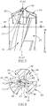
- the present invention further relates to a rotary cutting tool 52 comprising the tool shank 20 and a cutting head 54 releasably mounted in the head receiving pocket 22 of the tool shank 20.
- the cutting head 54 may preferably be manufactured by form pressing and sintering a cemented carbide, such as tungsten carbide, and may be coated or uncoated.
- the cutting head 54 has a cutting portion 56 and a mounting portion 58, and the mounting portion 58 has a base surface 60 and an engagement member 62 protruding therefrom along a head axis A3.
- the engagement member 62 may be located distal from the cutting portion 56.
- the engagement member 62 may be non-circular.
- the base surface 60 may make contact with the support surface 30, or a plurality of shoulder surfaces 63 offset therefrom.
- first diameter D1 of the imaginary first circle C1 is measured in a non-assembled position, in which the engagement member 62 is not resiliently retained in the central recess 32.
- the imaginary first circle C1 has a first assembly diameter D A 1 .
- the plurality of engagement surfaces 64 may make contact with the plurality of abutment surfaces 42 belonging to the central recess 32.
- the plurality of engagement surfaces 64 may diverge in the rearward direction D R , and the engagement member 62 may have a dovetail shape.
- each engagement surface 64 has a third circumferential angular extent E3.
- the second circumferential angular extent E2 may be greater than the third circumferential angular extent E3.
- an imaginary third circle C3 coaxial with the longitudinal axis of rotation A1 circumscribes the engagement member 62.
- the imaginary third circle C3 may contact the plurality of engagement surfaces 64.
- the plurality of joining surfaces 66 may be located inside the imaginary third circle C3.
- the plurality of engagement surfaces 64 may form a plurality of spaced apart engagement arcs 68 coincident with the imaginary third circle C3.
- the imaginary third circle C3 may have a third diameter D3 equal to the first assembly diameter D A 1 .
- the mounting portion 58 may have a plurality of circumferentially spaced apart side surfaces 70 extending away from the base surface 60 towards the cutting portion 56, with each side surface 70 including a torque transmission surface 72.
- each drive surface 36 may make contact with one of the torque transmission surfaces 72.
- each side surface 70 may include a flute extension surface 74, and each flute extension surface 74 may intersect a leading surface 76 of the cutting portion 56 to form a cutting edge 78.
- a plurality of head peripheral surfaces 80 may circumferentially alternate with the plurality of side surfaces 70, and each flute extension surface 74 may intersect one of the head peripheral surfaces 80 to form a leading edge 82.
- the present invention further relates to a method of assembling the rotary cutting tool 52, comprising the steps of:
- the engagement member 62 may be inserted into the central recess 32 until the base surface 60 makes contact with the support surface 30, or the plurality of shoulder surfaces 63.
- the cutting head 54 may be rotated about its head axis A3 in a direction opposite to the rotation direction R until each drive surface 36 makes contact with one of the torque transmission surfaces 72.
Landscapes
- Engineering & Computer Science (AREA)
- Mechanical Engineering (AREA)
- Milling Processes (AREA)
- Drilling Tools (AREA)
- Drilling And Exploitation, And Mining Machines And Methods (AREA)
Claims (14)
- Werkzeugschaft (20), der eine Drehungslängsachse (Al) aufweist, die eine Richtung von vorne nach hinten (DF, DR) festlegt, und der aufweist:eine Kopfaufnahmetasche (22) an einem vorderen Ende (24) und mehrere Spannuten (26), die sich in der Rückwärtsrichtung (DR) davon entlang der Drehungslängsachse (Al) erstrecken,wobei die Kopfaufnahmetasche (22) eine Haltefläche (30) quer zur Drehungslängsachse (Al) und eine mittlere Aussparung (32) aufweist,wobei:die mittlere Aussparung (32) in der Haltefläche (30) ausgebildet ist und sich davon in der Rückwärtsrichtung (DR) entlang der Drehungslängsachse (A1) erstreckt,die mittlere Aussparung (32) mehrere elastisch verschiebbare Auflageabschnitte (38) aufweist, die sich in Umfangsrichtung mit mehreren Zwischenabschnitten (40) abwechseln und durch diese beabstandet sind,jeder Auflageabschnitt (38) eine radial nach innen weisende Auflagefläche (42) aufweist, undjeder Zwischenabschnitt (40) eine Zwischenfläche (44) aufweist, die zwei in Umfangsrichtung benachbarte Auflageflächen (42) schneidet,dadurch gekennzeichnet, dass die mittlere Aussparung (32) keine der mehreren Spannuten (26) schneidet.
- Werkzeugschaft (20) nach Anspruch 1, wobei
in einem Querschnitt, der in einer ersten Ebene (P1) senkrecht zur Drehungslängsachse (A1) vorgenommen ist und durch die mittlere Aussparung (32) verläuft:jede Auflagefläche (42) eine erste Umfangswinkelausdehnung (E1) aufweist,jede Zwischenfläche (44) eine zweite Umfangswinkelausdehnung (E2) aufweist, unddie kombinierte Umfangswinkelausdehnung der mehreren Auflageflächen (42) und der mehreren Zwischenflächen (44) gleich 360° ist. - Werkzeugschaft (20) nach Anspruch 1 oder 2, wobei:
in einem Querschnitt, der in einer ersten Ebene (P1) senkrecht zur Drehungslängsachse (A1) vorgenommen ist und durch die mittlere Aussparung (32) verläuft:
ein imaginärer erster Kreis (C1), der koaxial zur Drehungslängsachse (A1) verläuft, die mittlere Aussparung (32) einbeschreibt. - Werkzeugschaft (20) nach Anspruch 3, wobei
im Querschnitt in der ersten Ebene (P1):ein imaginärer zweiter Kreis (C2), der koaxial zur Drehungslängsachse (A1) ist, die mehreren Spannuten (26) an mehreren ersten Nutpunkten (NF1) tangiert, undeine dritte Ebene (P3), die die Drehungslängsachse (A1) und mindestens einen der ersten Nutpunkte (NF1) enthält, mindestens eine der Auflageflächen (42) schneidet. - Werkzeugschaft (20) nach Anspruch 4, wobei:der imaginäre erste Kreis (C1) einen ersten Durchmesser (D1) aufweist,der imaginäre zweite Kreis (C2) einen zweiten Durchmesser (D2) aufweist, undder erste Durchmesser (D1) größer als die Hälfte des zweiten Durchmessers (D2) ist.
- Werkzeugschaft (20) nach Anspruch 4 oder 5, wobei:eine radiale Achse (A2) am Schnittpunkt der ersten und dritten Ebene (P1, P3) ausgebildet ist, undjeder erste Nutpunkt (NF1) in einem minimalen ersten Abstand (d1) von seiner benachbarten Auflagefläche (42) entlang der radialen Achse (A2) angeordnet ist.
- Werkzeugschaft (22) nach Anspruch 6, wobei
im Querschnitt in der ersten Ebene (P1):jede Spannut (26) einen zweiten Nutpunkt (NF2) aufweist, der vom ersten Nutpunkt (NF1) beabstandet ist,der zweite Nutpunkt (NF2) in einem minimalen zweiten Abstand (d2) von seiner benachbarten Zwischenfläche (44) angeordnet ist, undder minimale zweite Abstand (d2) gleich oder kleiner ist als der minimale erste Abstand (d1). - Werkzeugschaft (20) nach einem der Ansprüche 3 bis 7, wobei:
der imaginäre erste Kreis (Cl) die mehreren Auflageflächen (42) berührt. - Werkzeugschaft (20) nach einem der vorhergehenden Ansprüche, wobei:
die mehreren Auflageabschnitte (38) in einer radial nach außen gerichteten Richtung (Do) elastisch verschiebbar sind. - Drehschneidwerkzeug (52), das den Werkzeugschaft (20) nach einem der vorhergehenden Ansprüche und einen Schneidkopf (54) aufweist, der lösbar in der Kopfaufnahmetasche (22) angebracht ist,wobei der Schneidkopf (54) aufweist:einen Schneidabschnitt (56) und einen Montageabschnitt (58),wobei der Montageabschnitt (58) eine Basisfläche (60) und ein Eingriffselement (62) aufweist, das davon entlang einer Kopfachse (A3) vorsteht,wobei in einer zusammengebauten Position:die Basisfläche (60) der Haltefläche (30) gegenüberliegt,die Kopfachse (A3) mit der Drehungslängsachse (A1) zusammenfällt, unddas Eingriffselement (62) elastisch in der mittleren Aussparung (32) an den mehreren Auflageflächen (42) gehalten wird.
- Drehschneidwerkzeug (52) nach Anspruch 10, wobeiin einem Querschnitt, der in einer ersten Ebene (P1) senkrecht zur Drehungslängsachse (A1) aufgenommen ist und durch die mittlere Aussparung (32) verläuft:
ein imaginärer erster Kreis (C1) koaxial zur Drehungslängsachse (A1) die mittlere Aussparung (32) einbeschreibt, undwobei:in einer nicht montierten Position, in der das Eingriffselement (62) nicht elastisch in der mittleren Aussparung (32) gehalten wird, der imaginäre erste Kreis (C1) einen ersten Durchmesser (D1) aufweist,in der montierten Position der imaginäre erste Kreis (Cl) einen ersten Montagedurchmesser (DA1) aufweist, undder erste Durchmesser (D1) kleiner ist als der erste Montagedurchmesser (DA1). - Drehschneidwerkzeug (52) nach Anspruch 10 oder 11, wobei:das Eingriffselement (62) mehrere radial nach außen weisende Eingriffsflächen (64) aufweist, die sich in Umfangsrichtung mit mehreren Verbindungsflächen (66) abwechseln, unddie mehreren Eingriffsflächen (64) mit den mehreren Auflageflächen (42) in Kontakt kommen.
- Verfahren zum Zusammenbauen des Drehschneidwerkzeugs (52) nach einem der Ansprüche 10 bis 12,
wobei das Eingriffselement (62) mehrere radial nach außen weisende Eingriffsflächen (64) aufweist, die sich in Umfangsrichtung mit mehreren Verbindungsflächen (66) abwechseln,
das die Schritte aufweist:a) Ausrichten der Basisfläche (60), so dass sie der Haltefläche (30) gegenüberliegt;b) Ausrichten der Kopfachse (A3) mit der Drehungslängsachse (A1);c) drehendes Ausrichten der mehreren Eingriffsflächen (64) mit den mehreren Zwischenflächen (44);d) Einsetzen des Eingriffselements (62) in die mittlere Aussparung (32); unde) Drehen des Schneidkopfes (54) um seine Kopfachse (A3), bis die mehreren Eingriffsflächen (64) elastisch an den mehreren Auflageflächen (42) gehalten werden. - Verfahren nach Anspruch 13, wobei:
im Schritt d) das Eingriffselement (62) in die mittlere Aussparung (32) eingeführt wird, bis die Basisfläche (60) mit der Auflagefläche (30) oder mehreren davon abgesetzten Schulterflächen (63) in Kontakt kommt.
Applications Claiming Priority (2)
| Application Number | Priority Date | Filing Date | Title |
|---|---|---|---|
| US201662384401P | 2016-09-07 | 2016-09-07 | |
| PCT/IL2017/050875 WO2018047155A1 (en) | 2016-09-07 | 2017-08-08 | Tool shank with head support surface having central recess provided with resiliently displaceable abutment portions |
Publications (2)
| Publication Number | Publication Date |
|---|---|
| EP3509782A1 EP3509782A1 (de) | 2019-07-17 |
| EP3509782B1 true EP3509782B1 (de) | 2022-11-16 |
Family
ID=59846611
Family Applications (1)
| Application Number | Title | Priority Date | Filing Date |
|---|---|---|---|
| EP17764910.0A Active EP3509782B1 (de) | 2016-09-07 | 2017-08-08 | Werkzeugschaft mit kopfstützfläche mit zentraler aussparung, die mit elastisch verschiebbaren auflageabschnitten versehen ist |
Country Status (14)
| Country | Link |
|---|---|
| US (1) | US10173271B2 (de) |
| EP (1) | EP3509782B1 (de) |
| JP (1) | JP7123035B2 (de) |
| KR (1) | KR102360620B1 (de) |
| CN (1) | CN109689260B (de) |
| BR (1) | BR112019004259B1 (de) |
| CA (1) | CA3035322A1 (de) |
| ES (1) | ES2931428T3 (de) |
| IL (1) | IL264371B (de) |
| PL (1) | PL3509782T3 (de) |
| PT (1) | PT3509782T (de) |
| RU (1) | RU2734219C2 (de) |
| TW (1) | TWI736664B (de) |
| WO (1) | WO2018047155A1 (de) |
Families Citing this family (10)
| Publication number | Priority date | Publication date | Assignee | Title |
|---|---|---|---|---|
| US11235397B2 (en) | 2016-12-16 | 2022-02-01 | Kennametal Inc. | Side-activated modular drill |
| US11110521B2 (en) | 2018-03-07 | 2021-09-07 | Iscar, Ltd. | Rotary cutting head having a rigid mounting protuberance and rotary cutting tool |
| DE102019116160A1 (de) | 2018-06-20 | 2019-12-24 | Kennametal Inc. | Seitlich geschlossener modularer Bohrer mit federunterstütztem Auswurf |
| US11090736B2 (en) | 2018-12-10 | 2021-08-17 | Kennametal Inc. | Side-activated modular drill |
| US11059109B2 (en) * | 2018-12-31 | 2021-07-13 | Iscar, Ltd. | Cutting head having torque transmission surfaces on a mounting protuberance and rotary cutting tool having such cutting head |
| US11471952B2 (en) | 2020-03-19 | 2022-10-18 | Kennametal Inc. | Cutting tool having replaceable cutting head and method of securing a replaceable cutting head |
| US11453070B2 (en) | 2020-05-21 | 2022-09-27 | Iscar, Ltd. | Rotatable cutting head having torque transmission surfaces on a mounting protuberance and rotary cutting tool |
| US11951553B2 (en) | 2021-03-29 | 2024-04-09 | Iscar, Ltd. | Rotatable cutting head having tip portion with three radially extending cutting edges forming a rectilinear rotational profile |
| US11883888B2 (en) * | 2021-06-28 | 2024-01-30 | Kennametal Inc. | Modular drill with enhanced bump-off capability |
| US11819926B2 (en) | 2021-11-16 | 2023-11-21 | Iscar, Ltd | Cutting head having four cutting portions and two convex clamping surfaces, and rotary cutting tool |
Citations (1)
| Publication number | Priority date | Publication date | Assignee | Title |
|---|---|---|---|---|
| US20090116920A1 (en) * | 2007-11-05 | 2009-05-07 | Taegutec Ltd. | Rotary Cutting Tool |
Family Cites Families (26)
| Publication number | Priority date | Publication date | Assignee | Title |
|---|---|---|---|---|
| DE19543233A1 (de) | 1995-11-07 | 1997-05-15 | Johne & Co Praezisionswerkzeug | Bohrwerkzeug mit auswechselbarer Spitze |
| IL125766A (en) | 1998-08-13 | 2002-12-01 | Iscar Ltd | The barrel of a tool and a rotating cutting head for placing on it in the form of a self-lining |
| SE0103752L (sv) * | 2001-11-13 | 2003-05-14 | Sandvik Ab | Roterbart verktyg för spånavskiljande bearbetning jämte skärdel härtill |
| SE524063C2 (sv) * | 2002-01-29 | 2004-06-22 | Sandvik Ab | Verktygskoppling för roterande verktyg där kopplingens hondel har ett triangulärt tvärsnitt |
| DE10207257B4 (de) | 2002-02-21 | 2021-02-18 | Kennametal Inc. | Rundlaufschneidwerkzeug mit auswechselbarem Schneideinsatz |
| IL162147A (en) | 2004-05-24 | 2008-03-20 | Gil Hecht | Drill with interchangeable head |
| US7244081B2 (en) * | 2004-09-09 | 2007-07-17 | Ingersoll Cutting Tool Company | Drill adapter for drill having central and lateral cutting inserts |
| US7309196B2 (en) | 2004-10-05 | 2007-12-18 | Kennametal Inc. | Modular drill |
| US7467915B2 (en) | 2004-10-06 | 2008-12-23 | Kennametal Inc. | Modular drill |
| DE102006012382A1 (de) | 2006-03-17 | 2007-09-20 | Kennametal Inc. | Drehwerkzeug, insbesondere Bohrwerkzeug sowie Werkzeugkopf für ein Drehwerkzeug |
| IL181296A0 (en) | 2007-02-12 | 2007-07-04 | Iscar Ltd | Tool with releasably mounted self-clamping cutting head |
| IL181295A (en) * | 2007-02-12 | 2011-07-31 | Iscar Ltd | A cutting tool that includes a self-locking release bar head |
| KR20080000544A (ko) * | 2007-11-05 | 2008-01-02 | 대구텍 주식회사 | 회전 절삭 툴 |
| IL195804A (en) | 2008-12-09 | 2012-12-31 | Iscar Ltd | A cutting tool with a detachable cutting head that folds itself |
| US8864425B2 (en) * | 2009-02-04 | 2014-10-21 | Osg Corporation | Bevel head replaceable rotary tool, bevel head and tool body |
| SE533855C2 (sv) * | 2009-06-23 | 2011-02-08 | Sandvik Intellectual Property | Roterbart verktyg för spånavskiljande bearbetning samt löstopp och grundkropp härför |
| JP4850291B2 (ja) * | 2009-08-18 | 2012-01-11 | オーエスジー株式会社 | スローアウェイ式回転工具 |
| WO2011070652A1 (ja) * | 2009-12-08 | 2011-06-16 | オーエスジー株式会社 | スローアウェイ式回転工具 |
| IL210893A (en) * | 2011-01-26 | 2015-01-29 | Iscar Ltd | Cutting Tools |
| US8992141B2 (en) * | 2012-04-04 | 2015-03-31 | Iscar, Ltd. | Cutting head having resilient male coupling member for cutting tool and method of assembly thereof |
| US9028180B2 (en) | 2012-04-04 | 2015-05-12 | Iscar, Ltd. | Cutting tool and cutting head with a resilient coupling portion |
| DE102012212146B4 (de) * | 2012-07-11 | 2024-02-01 | Kennametal Inc. | Kupplungsstelle für ein modulares Rotationswerkzeug sowie Werkzeugkopf und Träger für ein solches modulares Rotationswerkzeug |
| US8882413B2 (en) * | 2012-11-26 | 2014-11-11 | Iscar, Ltd. | Cutting tool and cutting insert with a rearward resilience slit |
| US9468979B2 (en) | 2014-06-17 | 2016-10-18 | Iscar, Ltd. | Rotary cutting tool including cutting head having coupling pin with guiding and fastening recesses |
| CN204108418U (zh) * | 2014-09-27 | 2015-01-21 | 台州市优丰工具制造有限公司 | 锥柄麻花钻 |
| JP6428492B2 (ja) | 2015-06-04 | 2018-11-28 | 株式会社タンガロイ | 固定構造および切削工具 |
-
2017
- 2017-08-08 PL PL17764910.0T patent/PL3509782T3/pl unknown
- 2017-08-08 PT PT177649100T patent/PT3509782T/pt unknown
- 2017-08-08 CA CA3035322A patent/CA3035322A1/en active Pending
- 2017-08-08 WO PCT/IL2017/050875 patent/WO2018047155A1/en unknown
- 2017-08-08 KR KR1020197003161A patent/KR102360620B1/ko active IP Right Grant
- 2017-08-08 EP EP17764910.0A patent/EP3509782B1/de active Active
- 2017-08-08 CN CN201780054748.1A patent/CN109689260B/zh active Active
- 2017-08-08 BR BR112019004259-8A patent/BR112019004259B1/pt active IP Right Grant
- 2017-08-08 ES ES17764910T patent/ES2931428T3/es active Active
- 2017-08-08 JP JP2019508216A patent/JP7123035B2/ja active Active
- 2017-08-08 RU RU2019102160A patent/RU2734219C2/ru active
- 2017-08-09 US US15/672,353 patent/US10173271B2/en active Active
- 2017-08-28 TW TW106129188A patent/TWI736664B/zh active
-
2019
- 2019-01-21 IL IL264371A patent/IL264371B/en unknown
Patent Citations (1)
| Publication number | Priority date | Publication date | Assignee | Title |
|---|---|---|---|---|
| US20090116920A1 (en) * | 2007-11-05 | 2009-05-07 | Taegutec Ltd. | Rotary Cutting Tool |
Also Published As
| Publication number | Publication date |
|---|---|
| PT3509782T (pt) | 2023-01-20 |
| PL3509782T3 (pl) | 2023-04-11 |
| US10173271B2 (en) | 2019-01-08 |
| CN109689260A (zh) | 2019-04-26 |
| IL264371B (en) | 2022-01-01 |
| JP7123035B2 (ja) | 2022-08-22 |
| IL264371A (en) | 2019-02-28 |
| TW201811470A (zh) | 2018-04-01 |
| CA3035322A1 (en) | 2018-03-15 |
| BR112019004259A2 (pt) | 2019-06-04 |
| RU2019102160A3 (de) | 2020-10-08 |
| ES2931428T3 (es) | 2022-12-29 |
| EP3509782A1 (de) | 2019-07-17 |
| KR102360620B1 (ko) | 2022-02-09 |
| TWI736664B (zh) | 2021-08-21 |
| KR20190046776A (ko) | 2019-05-07 |
| BR112019004259B1 (pt) | 2022-05-31 |
| RU2019102160A (ru) | 2020-10-08 |
| CN109689260B (zh) | 2020-08-18 |
| RU2734219C2 (ru) | 2020-10-13 |
| US20180065191A1 (en) | 2018-03-08 |
| WO2018047155A1 (en) | 2018-03-15 |
| JP2019526460A (ja) | 2019-09-19 |
Similar Documents
| Publication | Publication Date | Title |
|---|---|---|
| EP3509782B1 (de) | Werkzeugschaft mit kopfstützfläche mit zentraler aussparung, die mit elastisch verschiebbaren auflageabschnitten versehen ist | |
| EP1107844B1 (de) | Schneidkopf / werkzeughalter kupplung | |
| EP1753573B1 (de) | Bohrer mit freigebbar montiertem schneidkopf | |
| US5816753A (en) | Port cutting tool with multiple function inserts | |
| CN111386166B (zh) | 用于高速进给的铣削和钻削的具有锥形腰部的双面可转位刀片 | |
| US11110521B2 (en) | Rotary cutting head having a rigid mounting protuberance and rotary cutting tool | |
| US11059109B2 (en) | Cutting head having torque transmission surfaces on a mounting protuberance and rotary cutting tool having such cutting head | |
| JP2007136563A (ja) | インサート式ドリル | |
| RU2773882C2 (ru) | Вращающаяся режущая головка, имеющая жесткий установочный выступ, и вращающийся режущий инструмент | |
| US11453070B2 (en) | Rotatable cutting head having torque transmission surfaces on a mounting protuberance and rotary cutting tool | |
| US11819926B2 (en) | Cutting head having four cutting portions and two convex clamping surfaces, and rotary cutting tool | |
| JP2020163497A (ja) | 刃先交換式ドリル、切削インサート、およびドリル本体 |
Legal Events
| Date | Code | Title | Description |
|---|---|---|---|
| STAA | Information on the status of an ep patent application or granted ep patent |
Free format text: STATUS: UNKNOWN |
|
| STAA | Information on the status of an ep patent application or granted ep patent |
Free format text: STATUS: THE INTERNATIONAL PUBLICATION HAS BEEN MADE |
|
| PUAI | Public reference made under article 153(3) epc to a published international application that has entered the european phase |
Free format text: ORIGINAL CODE: 0009012 |
|
| STAA | Information on the status of an ep patent application or granted ep patent |
Free format text: STATUS: REQUEST FOR EXAMINATION WAS MADE |
|
| 17P | Request for examination filed |
Effective date: 20190325 |
|
| AK | Designated contracting states |
Kind code of ref document: A1 Designated state(s): AL AT BE BG CH CY CZ DE DK EE ES FI FR GB GR HR HU IE IS IT LI LT LU LV MC MK MT NL NO PL PT RO RS SE SI SK SM TR |
|
| AX | Request for extension of the european patent |
Extension state: BA ME |
|
| DAV | Request for validation of the european patent (deleted) | ||
| DAX | Request for extension of the european patent (deleted) | ||
| STAA | Information on the status of an ep patent application or granted ep patent |
Free format text: STATUS: EXAMINATION IS IN PROGRESS |
|
| 17Q | First examination report despatched |
Effective date: 20200414 |
|
| STAA | Information on the status of an ep patent application or granted ep patent |
Free format text: STATUS: EXAMINATION IS IN PROGRESS |
|
| GRAP | Despatch of communication of intention to grant a patent |
Free format text: ORIGINAL CODE: EPIDOSNIGR1 |
|
| STAA | Information on the status of an ep patent application or granted ep patent |
Free format text: STATUS: GRANT OF PATENT IS INTENDED |
|
| INTG | Intention to grant announced |
Effective date: 20220607 |
|
| GRAS | Grant fee paid |
Free format text: ORIGINAL CODE: EPIDOSNIGR3 |
|
| GRAA | (expected) grant |
Free format text: ORIGINAL CODE: 0009210 |
|
| STAA | Information on the status of an ep patent application or granted ep patent |
Free format text: STATUS: THE PATENT HAS BEEN GRANTED |
|
| AK | Designated contracting states |
Kind code of ref document: B1 Designated state(s): AL AT BE BG CH CY CZ DE DK EE ES FI FR GB GR HR HU IE IS IT LI LT LU LV MC MK MT NL NO PL PT RO RS SE SI SK SM TR |
|
| REG | Reference to a national code |
Ref country code: GB Ref legal event code: FG4D |
|
| REG | Reference to a national code |
Ref country code: CH Ref legal event code: EP |
|
| REG | Reference to a national code |
Ref country code: IE Ref legal event code: FG4D |
|
| REG | Reference to a national code |
Ref country code: DE Ref legal event code: R096 Ref document number: 602017063752 Country of ref document: DE |
|
| REG | Reference to a national code |
Ref country code: AT Ref legal event code: REF Ref document number: 1531481 Country of ref document: AT Kind code of ref document: T Effective date: 20221215 |
|
| REG | Reference to a national code |
Ref country code: ES Ref legal event code: FG2A Ref document number: 2931428 Country of ref document: ES Kind code of ref document: T3 Effective date: 20221229 |
|
| REG | Reference to a national code |
Ref country code: PT Ref legal event code: SC4A Ref document number: 3509782 Country of ref document: PT Date of ref document: 20230120 Kind code of ref document: T Free format text: AVAILABILITY OF NATIONAL TRANSLATION Effective date: 20230116 |
|
| REG | Reference to a national code |
Ref country code: SE Ref legal event code: TRGR |
|
| REG | Reference to a national code |
Ref country code: LT Ref legal event code: MG9D |
|
| REG | Reference to a national code |
Ref country code: NL Ref legal event code: MP Effective date: 20221116 |
|
| PG25 | Lapsed in a contracting state [announced via postgrant information from national office to epo] |
Ref country code: NO Free format text: LAPSE BECAUSE OF FAILURE TO SUBMIT A TRANSLATION OF THE DESCRIPTION OR TO PAY THE FEE WITHIN THE PRESCRIBED TIME-LIMIT Effective date: 20230216 Ref country code: LT Free format text: LAPSE BECAUSE OF FAILURE TO SUBMIT A TRANSLATION OF THE DESCRIPTION OR TO PAY THE FEE WITHIN THE PRESCRIBED TIME-LIMIT Effective date: 20221116 Ref country code: FI Free format text: LAPSE BECAUSE OF FAILURE TO SUBMIT A TRANSLATION OF THE DESCRIPTION OR TO PAY THE FEE WITHIN THE PRESCRIBED TIME-LIMIT Effective date: 20221116 |
|
| PG25 | Lapsed in a contracting state [announced via postgrant information from national office to epo] |
Ref country code: RS Free format text: LAPSE BECAUSE OF FAILURE TO SUBMIT A TRANSLATION OF THE DESCRIPTION OR TO PAY THE FEE WITHIN THE PRESCRIBED TIME-LIMIT Effective date: 20221116 Ref country code: LV Free format text: LAPSE BECAUSE OF FAILURE TO SUBMIT A TRANSLATION OF THE DESCRIPTION OR TO PAY THE FEE WITHIN THE PRESCRIBED TIME-LIMIT Effective date: 20221116 Ref country code: IS Free format text: LAPSE BECAUSE OF FAILURE TO SUBMIT A TRANSLATION OF THE DESCRIPTION OR TO PAY THE FEE WITHIN THE PRESCRIBED TIME-LIMIT Effective date: 20230316 Ref country code: HR Free format text: LAPSE BECAUSE OF FAILURE TO SUBMIT A TRANSLATION OF THE DESCRIPTION OR TO PAY THE FEE WITHIN THE PRESCRIBED TIME-LIMIT Effective date: 20221116 Ref country code: GR Free format text: LAPSE BECAUSE OF FAILURE TO SUBMIT A TRANSLATION OF THE DESCRIPTION OR TO PAY THE FEE WITHIN THE PRESCRIBED TIME-LIMIT Effective date: 20230217 |
|
| P01 | Opt-out of the competence of the unified patent court (upc) registered |
Effective date: 20230426 |
|
| PG25 | Lapsed in a contracting state [announced via postgrant information from national office to epo] |
Ref country code: NL Free format text: LAPSE BECAUSE OF FAILURE TO SUBMIT A TRANSLATION OF THE DESCRIPTION OR TO PAY THE FEE WITHIN THE PRESCRIBED TIME-LIMIT Effective date: 20221116 |
|
| PG25 | Lapsed in a contracting state [announced via postgrant information from national office to epo] |
Ref country code: SM Free format text: LAPSE BECAUSE OF FAILURE TO SUBMIT A TRANSLATION OF THE DESCRIPTION OR TO PAY THE FEE WITHIN THE PRESCRIBED TIME-LIMIT Effective date: 20221116 Ref country code: RO Free format text: LAPSE BECAUSE OF FAILURE TO SUBMIT A TRANSLATION OF THE DESCRIPTION OR TO PAY THE FEE WITHIN THE PRESCRIBED TIME-LIMIT Effective date: 20221116 Ref country code: EE Free format text: LAPSE BECAUSE OF FAILURE TO SUBMIT A TRANSLATION OF THE DESCRIPTION OR TO PAY THE FEE WITHIN THE PRESCRIBED TIME-LIMIT Effective date: 20221116 Ref country code: DK Free format text: LAPSE BECAUSE OF FAILURE TO SUBMIT A TRANSLATION OF THE DESCRIPTION OR TO PAY THE FEE WITHIN THE PRESCRIBED TIME-LIMIT Effective date: 20221116 |
|
| REG | Reference to a national code |
Ref country code: DE Ref legal event code: R097 Ref document number: 602017063752 Country of ref document: DE |
|
| PG25 | Lapsed in a contracting state [announced via postgrant information from national office to epo] |
Ref country code: SK Free format text: LAPSE BECAUSE OF FAILURE TO SUBMIT A TRANSLATION OF THE DESCRIPTION OR TO PAY THE FEE WITHIN THE PRESCRIBED TIME-LIMIT Effective date: 20221116 Ref country code: AL Free format text: LAPSE BECAUSE OF FAILURE TO SUBMIT A TRANSLATION OF THE DESCRIPTION OR TO PAY THE FEE WITHIN THE PRESCRIBED TIME-LIMIT Effective date: 20221116 |
|
| REG | Reference to a national code |
Ref country code: AT Ref legal event code: UEP Ref document number: 1531481 Country of ref document: AT Kind code of ref document: T Effective date: 20221116 |
|
| PLBE | No opposition filed within time limit |
Free format text: ORIGINAL CODE: 0009261 |
|
| STAA | Information on the status of an ep patent application or granted ep patent |
Free format text: STATUS: NO OPPOSITION FILED WITHIN TIME LIMIT |
|
| 26N | No opposition filed |
Effective date: 20230817 |
|
| PGFP | Annual fee paid to national office [announced via postgrant information from national office to epo] |
Ref country code: IT Payment date: 20230718 Year of fee payment: 7 Ref country code: GB Payment date: 20230705 Year of fee payment: 7 Ref country code: AT Payment date: 20230706 Year of fee payment: 7 |
|
| PG25 | Lapsed in a contracting state [announced via postgrant information from national office to epo] |
Ref country code: SI Free format text: LAPSE BECAUSE OF FAILURE TO SUBMIT A TRANSLATION OF THE DESCRIPTION OR TO PAY THE FEE WITHIN THE PRESCRIBED TIME-LIMIT Effective date: 20221116 |
|
| PGFP | Annual fee paid to national office [announced via postgrant information from national office to epo] |
Ref country code: SE Payment date: 20230718 Year of fee payment: 7 Ref country code: FR Payment date: 20230706 Year of fee payment: 7 Ref country code: DE Payment date: 20230705 Year of fee payment: 7 |
|
| PGFP | Annual fee paid to national office [announced via postgrant information from national office to epo] |
Ref country code: ES Payment date: 20230930 Year of fee payment: 7 |
|
| PG25 | Lapsed in a contracting state [announced via postgrant information from national office to epo] |
Ref country code: MC Free format text: LAPSE BECAUSE OF FAILURE TO SUBMIT A TRANSLATION OF THE DESCRIPTION OR TO PAY THE FEE WITHIN THE PRESCRIBED TIME-LIMIT Effective date: 20221116 |
|
| REG | Reference to a national code |
Ref country code: CH Ref legal event code: PL |
|
| PG25 | Lapsed in a contracting state [announced via postgrant information from national office to epo] |
Ref country code: MC Free format text: LAPSE BECAUSE OF FAILURE TO SUBMIT A TRANSLATION OF THE DESCRIPTION OR TO PAY THE FEE WITHIN THE PRESCRIBED TIME-LIMIT Effective date: 20221116 |
|
| PG25 | Lapsed in a contracting state [announced via postgrant information from national office to epo] |
Ref country code: LU Free format text: LAPSE BECAUSE OF NON-PAYMENT OF DUE FEES Effective date: 20230808 |
|
| PG25 | Lapsed in a contracting state [announced via postgrant information from national office to epo] |
Ref country code: LU Free format text: LAPSE BECAUSE OF NON-PAYMENT OF DUE FEES Effective date: 20230808 Ref country code: CH Free format text: LAPSE BECAUSE OF NON-PAYMENT OF DUE FEES Effective date: 20230831 |
|
| REG | Reference to a national code |
Ref country code: BE Ref legal event code: MM Effective date: 20230831 |
|
| REG | Reference to a national code |
Ref country code: IE Ref legal event code: MM4A |
|
| PG25 | Lapsed in a contracting state [announced via postgrant information from national office to epo] |
Ref country code: IE Free format text: LAPSE BECAUSE OF NON-PAYMENT OF DUE FEES Effective date: 20230808 |
|
| PGFP | Annual fee paid to national office [announced via postgrant information from national office to epo] |
Ref country code: CZ Payment date: 20240620 Year of fee payment: 8 |
|
| PG25 | Lapsed in a contracting state [announced via postgrant information from national office to epo] |
Ref country code: IE Free format text: LAPSE BECAUSE OF NON-PAYMENT OF DUE FEES Effective date: 20230808 |
|
| PGFP | Annual fee paid to national office [announced via postgrant information from national office to epo] |
Ref country code: PL Payment date: 20240606 Year of fee payment: 8 Ref country code: PT Payment date: 20240605 Year of fee payment: 8 |
|
| PG25 | Lapsed in a contracting state [announced via postgrant information from national office to epo] |
Ref country code: BE Free format text: LAPSE BECAUSE OF NON-PAYMENT OF DUE FEES Effective date: 20230831 |
|
| PGFP | Annual fee paid to national office [announced via postgrant information from national office to epo] |
Ref country code: TR Payment date: 20240614 Year of fee payment: 8 |