EP3508308B1 - Dispositif de percussion hydraulique - Google Patents
Dispositif de percussion hydraulique Download PDFInfo
- Publication number
- EP3508308B1 EP3508308B1 EP17846183.6A EP17846183A EP3508308B1 EP 3508308 B1 EP3508308 B1 EP 3508308B1 EP 17846183 A EP17846183 A EP 17846183A EP 3508308 B1 EP3508308 B1 EP 3508308B1
- Authority
- EP
- European Patent Office
- Prior art keywords
- valve
- piston
- chamber
- switching
- low pressure
- Prior art date
- Legal status (The legal status is an assumption and is not a legal conclusion. Google has not performed a legal analysis and makes no representation as to the accuracy of the status listed.)
- Active
Links
- 230000007246 mechanism Effects 0.000 claims description 32
- 238000004904 shortening Methods 0.000 claims description 12
- 230000002093 peripheral effect Effects 0.000 claims description 7
- 239000003921 oil Substances 0.000 description 44
- 238000004891 communication Methods 0.000 description 27
- 238000007789 sealing Methods 0.000 description 10
- 230000035939 shock Effects 0.000 description 9
- 230000003111 delayed effect Effects 0.000 description 7
- 238000010586 diagram Methods 0.000 description 7
- 230000000694 effects Effects 0.000 description 7
- 230000010349 pulsation Effects 0.000 description 7
- 239000000470 constituent Substances 0.000 description 6
- 238000000034 method Methods 0.000 description 6
- 238000009825 accumulation Methods 0.000 description 4
- 230000009471 action Effects 0.000 description 4
- 238000007599 discharging Methods 0.000 description 4
- 230000008569 process Effects 0.000 description 4
- 230000001902 propagating effect Effects 0.000 description 4
- 230000003139 buffering effect Effects 0.000 description 3
- 230000008859 change Effects 0.000 description 2
- 230000004048 modification Effects 0.000 description 2
- 238000012986 modification Methods 0.000 description 2
- 239000007787 solid Substances 0.000 description 2
- 230000007704 transition Effects 0.000 description 2
- 230000004075 alteration Effects 0.000 description 1
- 230000007812 deficiency Effects 0.000 description 1
- 238000005516 engineering process Methods 0.000 description 1
- 239000010720 hydraulic oil Substances 0.000 description 1
- 239000000463 material Substances 0.000 description 1
- 230000000149 penetrating effect Effects 0.000 description 1
- 239000011435 rock Substances 0.000 description 1
Images


Classifications
-
- B—PERFORMING OPERATIONS; TRANSPORTING
- B25—HAND TOOLS; PORTABLE POWER-DRIVEN TOOLS; MANIPULATORS
- B25D—PERCUSSIVE TOOLS
- B25D9/00—Portable percussive tools with fluid-pressure drive, i.e. driven directly by fluids, e.g. having several percussive tool bits operated simultaneously
- B25D9/14—Control devices for the reciprocating piston
- B25D9/26—Control devices for adjusting the stroke of the piston or the force or frequency of impact thereof
-
- B—PERFORMING OPERATIONS; TRANSPORTING
- B25—HAND TOOLS; PORTABLE POWER-DRIVEN TOOLS; MANIPULATORS
- B25D—PERCUSSIVE TOOLS
- B25D9/00—Portable percussive tools with fluid-pressure drive, i.e. driven directly by fluids, e.g. having several percussive tool bits operated simultaneously
- B25D9/14—Control devices for the reciprocating piston
- B25D9/145—Control devices for the reciprocating piston for hydraulically actuated hammers having an accumulator
-
- B—PERFORMING OPERATIONS; TRANSPORTING
- B25—HAND TOOLS; PORTABLE POWER-DRIVEN TOOLS; MANIPULATORS
- B25D—PERCUSSIVE TOOLS
- B25D9/00—Portable percussive tools with fluid-pressure drive, i.e. driven directly by fluids, e.g. having several percussive tool bits operated simultaneously
- B25D9/14—Control devices for the reciprocating piston
- B25D9/16—Valve arrangements therefor
- B25D9/18—Valve arrangements therefor involving a piston-type slide valve
-
- B—PERFORMING OPERATIONS; TRANSPORTING
- B25—HAND TOOLS; PORTABLE POWER-DRIVEN TOOLS; MANIPULATORS
- B25D—PERCUSSIVE TOOLS
- B25D9/00—Portable percussive tools with fluid-pressure drive, i.e. driven directly by fluids, e.g. having several percussive tool bits operated simultaneously
- B25D9/14—Control devices for the reciprocating piston
- B25D9/16—Valve arrangements therefor
- B25D9/20—Valve arrangements therefor involving a tubular-type slide valve
-
- B—PERFORMING OPERATIONS; TRANSPORTING
- B25—HAND TOOLS; PORTABLE POWER-DRIVEN TOOLS; MANIPULATORS
- B25D—PERCUSSIVE TOOLS
- B25D2209/00—Details of portable percussive tools with fluid-pressure drive, i.e. driven directly by fluids, e.g. having several percussive tool bits operated simultaneously
- B25D2209/002—Pressure accumulators
-
- B—PERFORMING OPERATIONS; TRANSPORTING
- B25—HAND TOOLS; PORTABLE POWER-DRIVEN TOOLS; MANIPULATORS
- B25D—PERCUSSIVE TOOLS
- B25D2209/00—Details of portable percussive tools with fluid-pressure drive, i.e. driven directly by fluids, e.g. having several percussive tool bits operated simultaneously
- B25D2209/007—Details of portable percussive tools with fluid-pressure drive, i.e. driven directly by fluids, e.g. having several percussive tool bits operated simultaneously having a tubular-slide valve, which is not coaxial with the piston
-
- B—PERFORMING OPERATIONS; TRANSPORTING
- B25—HAND TOOLS; PORTABLE POWER-DRIVEN TOOLS; MANIPULATORS
- B25D—PERCUSSIVE TOOLS
- B25D2222/00—Materials of the tool or the workpiece
- B25D2222/72—Stone, rock or concrete
-
- B—PERFORMING OPERATIONS; TRANSPORTING
- B25—HAND TOOLS; PORTABLE POWER-DRIVEN TOOLS; MANIPULATORS
- B25D—PERCUSSIVE TOOLS
- B25D2250/00—General details of portable percussive tools; Components used in portable percussive tools
- B25D2250/125—Hydraulic tool components
Definitions
- the present invention relates to a hydraulic striking device, such as a rock drill and a breaker.
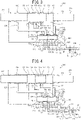
- FIG. 9 A hydraulic striking device described in PTL 1 will be described with reference to FIG. 9 as appropriate.
- the upper side of the axis illustrates a state of the piston or the valve when the piston is in a phase of turning from advancement to retraction
- the lower side of the axis illustrates a state of the piston or the valve when the piston is in a phase of turning from retraction to advancement.
- the hydraulic striking device includes a cylinder 500 and a piston 522, as illustrated in FIG. 9 .
- the piston 522 is a solid cylinder body and has piston large-diameter portions 523 and 524 substantially in the middle thereof.
- a piston medium-diameter portion 525 is disposed, and, in the rear of the piston large-diameter portion 524, a piston small-diameter portion 526 is disposed.
- annular valve switching groove 527 is formed.
- Outer diameter of the piston medium-diameter portion 525 is set larger than outer diameter of the piston small-diameter portion 526.
- This configuration causes the piston 522 to have a larger pressure receiving area in a piston rear chamber 502, to be described later, that is, a diameter difference between the piston large-diameter portion 524 and the piston small-diameter portion 526, than a pressure receiving area in a piston front chamber 501, to be described later, that is, a diameter difference between the piston large-diameter portion 523 and the piston medium-diameter portion 525.
- the piston 522 being slidably fitted in the inside of a cylinder 500 causes the piston front chamber 501 and the piston rear chamber 502 to be respectively defined inside the cylinder 500.
- the piston front chamber 501 is constantly connected to a high pressure circuit 513 via a piston front chamber passage 516.
- the piston rear chamber 502 is configured to be communicable with either the high pressure circuit 513 or a low pressure circuit 519 alternately through switching between advancement and retraction of the switching valve mechanism 540.
- a high pressure accumulator 536 and a low pressure accumulator 537 are disposed, respectively.
- the switching valve mechanism 540 includes, inside the cylinder 500, a valve chamber 506 formed in a non-concentric manner with the piston 522 and a valve 528 slidably fitted in the valve chamber 506.
- the valve chamber 506 has a valve front chamber 508, a valve main chamber 507, and a valve rear chamber 509 in sequence from the front to the rear.
- a piston rear chamber high pressure port 510, a piston rear chamber switching port 511, and a piston rear chamber low pressure port 512 are disposed separated from each other at predetermined intervals in sequence from the front to the rear.
- the valve 528 is a solid cylinder body and has valve large-diameter portions 529 and 530 substantially in the middle thereof.
- a valve medium-diameter portion 531 is disposed, and, in the rear of the valve large-diameter portion 530, a valve small-diameter portion 532 is disposed.
- a valve retraction restricting portion 533 that restricts the valve 528 from moving rearward is disposed.
- An annular piston rear chamber high pressure switching groove 534 and a piston rear chamber low pressure switching groove 535 are disposed between the valve large-diameter portions 529 and 530 and between the valve large-diameter portion 530 and the valve retraction restricting portion 533, respectively.
- valve large-diameter portions 529 and 530, the valve medium-diameter portion 531, and the valve small-diameter portion 532 are configured to be slidably fitted in the valve main chamber 507, the valve front chamber 508, and the valve rear chamber 509, respectively.
- Outer diameter of the valve medium-diameter portion 531 is set larger than outer diameter of the valve small-diameter portion 532. Therefore, pressure receiving area of the valve medium-diameter portion 531 side is configured to be larger than pressure receiving area of the valve small-diameter portion 532 side.
- a piston advancement control port (short stroke) 503a, a piston advancement control port 503, a piston retraction control port 504, and an oil discharge port 505 are disposed separated from each other at predetermined intervals from the front to the rear.
- the high pressure circuit 513 is connected to the piston rear chamber high pressure port 510 via a high pressure passage 514.
- the high pressure circuit 513 is connected to the piston front chamber 501 via the piston front chamber passage 516, which branches off from the high pressure passage 514, and therewith connected to the valve rear chamber 509 via a valve rear chamber passage 517, which branches off from the high pressure passage 514.
- valve control passage 518 To the valve front chamber 508, one end of a valve control passage 518 is connected, and the other end of the valve control passage 518 splits into a valve front chamber high pressure passage (short stroke) 518a, a valve front chamber high pressure passage 518b, and a valve front chamber low pressure passage 518c.
- the valve front chamber high pressure passage (short stroke) 518a is connected to the piston advancement control port (short stroke) 503a.
- valve front chamber high pressure passage 518b and the valve front chamber low pressure passage 518c are connected to the piston advancement control port 503 and the piston retraction control port 504, respectively.
- the piston rear chamber 502 is connected to the piston rear chamber switching port 511 via a piston rear chamber passage 515.
- the oil discharge port 505 is connected to the low pressure circuit 519 via a valve low pressure passage 520.
- the piston rear chamber low pressure port 512 is connected to the low pressure circuit 519 via a piston low pressure passage 521.
- the piston advancement control port (short stroke) 503a, the piston advancement control port 503, the valve front chamber high pressure passage (short stroke) 518a, and the valve front chamber high pressure passage 518b constitute a known stroke switching mechanism, and operation of a variable throttle disposed in the valve front chamber high pressure passage (short stroke) 518a enables a piston stroke to be adjusted steplessly from a short stroke (the variable throttle is in a full-open state) to a normal stroke (the variable throttle is in a full-close state).
- the piston 522 constantly is biased rearward because the piston front chamber 501 is constantly connected to high pressure.
- the piston 522 advances due to a pressure receiving area difference, and, when the piston rear chamber 502 is connected to low pressure through operation of the valve 528, the piston 522 retracts.
- the valve 528 is constantly biased forward because the valve rear chamber 509 is constantly connected to high pressure.
- the valve control passage 518 comes into communication with the valve front chamber 508 and the valve front chamber 508 is thereby connected to high pressure, the valve 528 retracts due to a pressure receiving area difference, and, when the valve control passage 518 comes into communication with the oil discharge port 505 and the valve front chamber 508 is thereby connected to low pressure, the valve 528 advances.
- a hydraulic striking device disclosing all features of the preamble of appended claim 1 is known from WO 2015/115105 A1 .
- a hydraulic striking device of this type is sometimes required to adjust striking power.
- Measures for adjusting striking power are considered to include a measure of disposing a pressure adjustment valve and reducing pressure of pressurized oil supplied to the hydraulic striking device and a measure of, by operating the stroke switching mechanism and shortening a stroke, reducing piston velocity at the time of strikes.
- the measure of disposing the pressure adjustment valve has a problem in that controllability is low, and the measure of using the stroke switching mechanism has a problem in that operability is low.
- the present invention has been made focusing on such problems, and a problem to be solved by the present invention is to provide a hydraulic striking device the striking characteristics of which can be easily changed.
- a hydraulic striking device including: a cylinder; a piston slidably fitted in an inside of the cylinder; a piston front chamber and a piston rear chamber defined between an outer peripheral surface of the piston and an inner peripheral surface of the cylinder and arranged separated from each other in axially front and rear directions; and a switching valve mechanism configured to switch the piston front chamber and the piston rear chamber into a high pressure state and a low pressure state in an interchanging manner, the piston being advanced and retracted in the cylinder to strike a rod for striking, wherein the switching valve mechanism includes a valve chamber formed in the cylinder in a non-concentric manner with the piston, a valve slidably fitted in the valve chamber and to which a high/low pressure switching portion for switching the piston front chamber and the piston rear chamber into a high pressure state and a low pressure state in an interchanging manner is formed, a valve biasing portion configured to constantly bias the valve forward, and a valve control portion configured
- time required for high/low pressure switching operation at the time of advancement and retraction of the piston in association with advancement of the valve in the forward operation mode is shortened, time required for high/low pressure switching operation at the time of advancement and retraction of the piston in association with advancement of the valve in the reverse operation mode is relatively extended.
- time required for switching from a low pressure state to a high pressure state in the forward operation mode becomes shorter than that in the reverse operation mode, which causes a piston retraction stroke in the forward operation mode to be shortened and the piston retraction stroke in the reverse operation mode to be relatively extended. Therefore, selection of the forward operation mode by means of the operation switching valve causes a stroke to be set at a short stroke and selection of the reverse operation mode causes a stroke to be set at a long stroke.
- the conventional stroke adjustment mechanism described above is a mechanism in which a stroke is adjusted by adjusting a degree of opening of the variable throttle disposed to the cylinder main body and is not suitable for a use in which a long stroke and a short stroke are switched in accordance with work details.
- the hydraulic striking device enables the operation switching valve to be disposed on the carriage main body side, no modification is necessary to the guide shell and related portions thereof.
- the shortening portion be a difference between an opening width of a port that is closed by the valve at the time of advancement of the valve and an opening width of a port that is closed by the valve at the time of retraction of the valve.
- Such a configuration makes it unnecessary to dispose an actuator separately because the shortening portion is the difference between the opening width of the port that is closed by the valve at the time of advancement of the valve and the opening width of the port that is closed by the valve at the time of retraction of the valve, and is suitable for achieving a stroke switching mechanism by use of a simple configuration.
- valve control portion include a delaying portion including a throttle configured to provide no restriction when pressurized oil is supplied and adjust a flow rate when pressurized oil is discharged.
- Such a configuration enables a piston stroke to be extended in the reverse operation mode because a delaying portion including the throttle configured to provide no restriction when pressurized oil is supplied and adjust a flow rate when pressurized oil is discharged is disposed to the valve control portion.
- a delaying portion including the throttle configured to provide no restriction when pressurized oil is supplied and adjust a flow rate when pressurized oil is discharged is disposed to the valve control portion.
- the hydraulic striking device include a high pressure accumulator disposed to the reverse operation circuit and a low pressure accumulator disposed to the forward operation circuit.
- Such a configuration is suitable because a high pressure accumulator and a low pressure accumulator are disposed to the reverse operation circuit and the forward operation circuit, respectively, and the high pressure accumulator and the low pressure accumulator are thereby arranged on the high pressure circuit side and the low pressure circuit side, respectively, in a connection state of the reverse operation mode, which is used by a regular work, that is, a state in which the reverse operation circuit and the forward operation circuit are connected to the high pressure circuit and the low pressure circuit, respectively.
- the hydraulic striking device include pairs of a high pressure accumulator and a low pressure accumulator respectively disposed to the reverse operation circuit and the forward operation circuit and that each of the pairs of the high pressure accumulator and the low pressure accumulator be disposed side by side in such a way that the high pressure accumulator is disposed on the switching valve mechanism side.
- Such a configuration is suitable because pairs of a high pressure accumulator and a low pressure accumulator are disposed to each of the reverse operation circuit and the forward operation circuit side by side in such a way that the high pressure accumulators are disposed on the switching valve mechanism side and the accumulators thereby work normally in both connection states, the reverse operation mode and the forward operation mode.
- a forward operation mode refers to a mode in which advancing and retracting movements of a piston and advancing and retracting movements of a valve operate in the same phase
- a reverse operation mode refers to a mode in which advancing and retracting movements of a piston and advancing and retracting movements of a valve operate in opposite phases.
- the reverse operation mode is often employed in the expectation that operating advancing and retracting movements of a piston and advancing and retracting movements of a valve in opposite phases causes reaction forces to offset each other, and a description will be made herein assuming the reverse operation mode to be a regular operation mode.
- the hydraulic striking device of the first embodiment includes a cylinder 100 and a piston 200 that is slidably fitted in the inside of the cylinder 100 in such a way as to be slidably movable along the axial direction.
- the piston 200 has a large-diameter portion (front) 201 and a large-diameter portion (rear) 202 in an axially middle portion and small-diameter portions 203 and 204 that are formed in front and rear of the large-diameter portions 201 and 202.
- an annular valve switching groove 205 is formed.
- the piston 200 being disposed slidably fitted in the cylinder 100 causes a piston front chamber 110 and a piston rear chamber 111 to be defined separated from each other in the axially front and rear directions, respectively, between the outer peripheral surface of the piston 200 and the inner peripheral surface of the cylinder 100.
- a switching valve mechanism 210 is disposed that switches communication of the piston front chamber 110 and the piston rear chamber 111 with a high pressure circuit 103 and a low pressure circuit 104 in an interchanging manner and supplies and discharges hydraulic oil so that advancing and retracting movements of the piston 200 are repeated.
- the switching valve mechanism 210 includes, inside the cylinder 100, a valve chamber 130 formed in a non-concentric manner with the piston 200 and a valve (spool) 300 slidably fitted in the valve chamber 130.
- the valve chamber 130 has a valve chamber small-diameter portion 132, a valve chamber large-diameter portion 131, and a valve chamber medium-diameter portion 133 formed in sequence from the front to the rear.
- a valve control chamber 137, a piston front chamber forward operation port 135, a piston reverse operation port 134, and a piston rear chamber forward operation port 136 are disposed separated from each other at predetermined intervals from the front to the rear.
- the base end side (carriage main body side) of the high pressure circuit 103 and the base end side of the low pressure circuit 104 are connected to a pump P and a tank T, respectively.
- the tip end side (cylinder 100 side) of the high pressure circuit 103 is connected to either a reverse operation circuit 101 or a forward operation circuit 102 via an operation switching valve 105 in a switchable manner.
- a high pressure accumulator 400 and a low pressure accumulator 401 are disposed, respectively.
- a piston front chamber passage 120 is connected that communicates the piston front chamber 110 with either the reverse operation circuit 101 or the forward operation circuit 102 through switching between advancement and retraction of the valve 300.
- a piston rear chamber passage 121 is connected that communicates the piston rear chamber 111 with either the reverse operation circuit 101 or the forward operation circuit 102 through switching between advancement and retraction of the valve 300.
- a piston retraction control port 113 Between the piston front chamber 110 and the piston rear chamber 111, a piston retraction control port 113, a valve control port 114, and piston advancement control ports 112 are disposed separated from each other at predetermined intervals from the front to the rear. With regard to the piston advancement control ports 112, opening portions for a normal stroke and a short stroke are disposed at two positions.
- a piston advancement control port 112a on the piston front chamber 110 side is a port that is for the short stroke and is provided with a variable throttle 127.
- a description will be made herein under the assumption that the normal stroke is set, that is, with the variable throttle 127 set at a full close state, the piston advancement control port 112 on the piston rear chamber 111 side works.
- valve 300 is a hollow cylindrically shaped valve body that has an axially penetrating valve hollow passage 311.
- the upper side of the axis illustrates a state in which the piston retraction control port 113 comes into communication while the piston 200 is advancing when the reverse operation circuit 101 is connected to the high pressure circuit 103 and the valve 300 thereby starts to move rearward ( FIG. 6B , to be described later) or a state in which the piston advancement control port 112 comes into communication while the piston 200 is retracting when the forward operation circuit 102 is connected to the high pressure circuit 103 and the valve 300 thereby starts to move rearward ( FIG. 7D , to be described later).
- the lower side of the axis illustrates a state in which the piston advancement control port 112 comes into communication while the piston 200 is retracting when the reverse operation circuit 101 is connected to the high pressure circuit 103 and the valve 300 thereby starts to move forward ( FIG. 6D , to be described later) or a state in which the piston retraction control port 113 comes into communication while the piston 200 is advancing when the forward operation circuit 102 is connected to the high pressure circuit 103 and the valve 300 thereby starts to move forward ( FIG. 7B , to be described later).
- the valve 300 has, on the outer peripheral surface, valve large-diameter portions 301, 302, and 303, a valve small-diameter portion 304 that is disposed in front of the valve large-diameter portion 301, and a valve medium-diameter portion 305 that is disposed in the rear of the valve large-diameter portion 303.
- an annular piston front chamber switching groove 306 is disposed between the valve large-diameter portions 301 and 302 .
- an annular piston rear chamber switching groove 307 is disposed between the valve large-diameter portions 302 and 303.
- these piston front chamber switching groove 306 and piston rear chamber switching groove 307 correspond to the "high/low pressure switching portion" described in Solution to Problem described above.
- the switching valve mechanism 210 is configured in such a way that the valve large-diameter portions 301, 302, and 303, the valve small-diameter portion 304, and the valve medium-diameter portion 305 are slidably fitted in the valve chamber large-diameter portion 131, the valve chamber small-diameter portion 132, and the valve chamber medium-diameter portion 133, respectively.
- the front end face and the rear end face of the valve 300 are a valve front end face 308 and a valve rear end face 309, respectively.
- a valve stepped face (front) 310 and a valve stepped face (rear) 312 are formed, respectively.
- valve main body reverse operation passages 313 that penetrate the valve large-diameter portion 302 in radial directions are disposed in such a way as to communicate with the valve hollow passage 311.
- a difference between the pressure receiving areas S2 and S1 corresponds to the "reverse operation biasing portion", described in Solution to Problem described above, that operates when the reverse operation circuit is connected to the high pressure circuit
- the pressure receiving area S4 corresponds to the "forward operation biasing portion", described in Solution to Problem described above, that operates when the forward operation circuit is connected to the high pressure circuit.
- the "reverse operation biasing portion” and the “forward operation biasing portion” correspond to the "valve biasing portion” described in Solution to Problem described above.
- the pressure receiving area S3 corresponds to the "valve control portion", described in Solution to Problem described above, that, when pressurized oil is supplied, moves the valve rearward against biasing force of the valve biasing portion.
- a sidewall on the front side of the piston reverse operation port 134, a sidewall on the rear side of the piston reverse operation port 134, a sidewall on the rear side of the piston front chamber forward operation port 135, a sidewall on the front side of the piston rear chamber forward operation port 136, a sidewall on the front side of the piston front chamber switching groove 306, a sidewall on the rear side of the piston front chamber switching groove 306, a sidewall on the front side of the piston rear chamber switching groove 307, and a sidewall on the rear side of the piston rear chamber switching groove 307 are denoted by reference numerals 134a, 134b, 135b, 136a, 306a, 306b, 307a, and 307b, respectively, relations among opening widths and sealing lengths of ports that the valve 300 and the valve chamber 130 cooperatively form are expressed as follows.
- the reverse operation circuit 101 and the forward operation circuit 102 are connected to the piston reverse operation port 134 and both the piston front chamber forward operation port 135 and the piston rear chamber forward operation port 136, respectively.
- One end and the other end of the piston front chamber passage 120 are connected to the piston front chamber 110 and an intermediate portion between the piston reverse operation port 134 and the piston front chamber forward operation port 135 of the valve chamber large-diameter portion 131, respectively.
- One end and the other end of the piston rear chamber passage 121 are connected to the piston rear chamber 111 and an intermediate portion between the piston reverse operation port 134 and the piston rear chamber forward operation port 136 of the valve chamber large-diameter portion 131, respectively.
- a valve reverse operation passage 123, a valve forward operation passage 125, and a valve control passage 126 connect between the piston retraction control port 113 and the front side end face of the valve chamber 130, between the piston advancement control port 112 and the piston rear chamber forward operation port 136, and between the valve control port 114 and the valve control chamber 137, respectively. Therefore, pressure in the valve hollow passage 311 is constantly high in the reverse operation mode and constantly low in the forward operation mode.
- the valve reverse operation passage 123 may directly connect between the piston retraction control port 113 and the piston reverse operation port 134 or may directly connect between the piston retraction control port 113 and the reverse operation circuit 101.
- the valve forward operation passage 125 may directly connect between the piston advancement control port 112 and the piston front chamber forward operation port 135 or may directly connect between the piston advancement control port 112 and the forward operation circuit 102.
- valve control passage 126 connecting between the valve control port 114 and the valve control chamber 137 in the first embodiment is altered into a valve control passage 126' by disposing a variable throttle 128 and a check valve 129 to the valve control passage 126.
- the check valve 129 is disposed in such a way as to allow pressurized oil to flow from the valve control port 114 side into the valve control chamber 137 and restrict pressurized oil from flowing out from the valve control chamber 137 side to the valve control port 114.
- the configuration made up of the variable throttle 128 and the check valve 129 corresponds to the "delaying portion" described in Solution to Problem described above.
- the delaying portion serves as a means for extending time required for high/low pressure switching operation in the piston front and rear chambers in association with retraction of the valve to be longer than time required for high/low pressure switching operation in the piston front and rear chambers in association with advancement of the valve. Therefore, the second embodiment includes both the "shortening portion" and the "delaying portion".
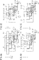
- a hydraulic striking device of a third embodiment of the present invention will be described with reference to FIG. 4 .
- a difference from the first embodiment is that, to a reverse operation circuit 101, a high pressure accumulator 400 and a low pressure accumulator 402 are disposed side by side in such a way that the high pressure accumulator 400 is disposed on the switching valve mechanism 210 side and, therewith, to a forward operation circuit 102, a high pressure accumulator 403 and a low pressure accumulator 401 are disposed side by side in such a way that the high pressure accumulator 403 is disposed on the switching valve mechanism 210 side.
- a hydraulic striking device of a fourth embodiment of the present invention will be described with reference to FIG. 5 .
- a difference from the first embodiment is that a high pressure accumulator 400 and a low pressure accumulator 401 are omitted, a back head 410 is disposed in the rear of a cylinder 100, and a space inside the back head 410 into which a piston 200 is inserted is formed into a gas chamber 411 that is filled with a gas.
- FIGS. 6A to 6D and 7A to 7D passages that are in a high pressure state and passages that are in a low pressure state are illustrated by "dark shading” and "bright shading", respectively.
- the operation switching valve 105 has been switched to the reverse operation mode, that is, a position at which the reverse operation circuit 101 and the high pressure circuit 103 are connected to each other (a position at which the forward operation circuit 102 and the low pressure circuit 104 are connected to each other).
- the piston reverse operation port 134 comes into communication with the piston rear chamber passage 121, which causes pressure in the piston rear chamber 111 to become high.
- the piston front chamber forward operation port 135 comes into communication with the piston front chamber passage 120, which causes pressure in the piston front chamber 110 to become low. This operation causes the piston 200 to advance.
- valve chamber 130 is constantly connected to the reverse operation circuit 101 via the valve main body reverse operation passages 313, which causes pressure at both the valve front end face 308 and the valve rear end face 309 to be kept high. Since high pressure works on both the valve front end face 308 and the valve rear end face 309, the valve 300 is held at the advanced position from Formula 3 described above (see FIG. 6A ).
- the piston 200 advances, communication between the valve control port 114 and the piston advancement control port 112 is cut off, and, instead thereof, the valve control port 114 comes into communication with the piston retraction control port 113.
- This operation causes high pressure oil from the valve reverse operation passage 123 to be supplied to the valve control chamber 137 via the valve control passage 126'. Since, at this time, the pressurized oil passes the check valve 129 in the valve control passage 126', flow of the pressurized oil is not adjusted by the variable throttle 128.
- valve control chamber 137 When pressure in the valve control chamber 137 becomes high, the high pressure works on the valve stepped face 310, which causes the valve 300 to start to retract from Formula 4 described above (see FIG. 6B ). At this time, the time required for high/low pressure switching operation in the piston front chamber 110 and the piston rear chamber 111 in association with retraction of the valve 300 is in proportion to Ln from Formula 6 described above.
- the piston 200 reaches an impact point when striking efficiency is maximum (between FIGS. 6B and 6C ), and, at the impact point, the tip of the piston 200 strikes the rear end of a rod for striking (not illustrated). This operation causes a shock wave produced by the strike to propagate to a bit or the like at the tip of the rod via the rod and to be used as energy for crushing bedrock or the like.
- valve 300 completes switching to a retracted position thereof.
- the piston reverse operation port 134 comes into communication with the piston front chamber passage 120, which causes pressure in the piston front chamber 110 to become high.
- the piston rear chamber forward operation port 136 comes into communication with the piston rear chamber passage 121, which causes pressure in the piston rear chamber 111 to become low. This operation causes the piston 200 to turn to retraction.
- pressure in the valve control chamber 137 is kept high, the valve 300 is held at the retracted position (see FIG. 6C ).
- valve control port 114 comes into communication with the piston advancement control port 112.
- This operation causes the valve control chamber 137 to be connected to the low pressure circuit 104 via the valve control passage 126' and the valve forward operation passage 125.
- pressure in the valve control chamber 137 becomes low, the valve 300 starts to advance from Formula 3 described above.
- the time required for high/low pressure switching operation in the piston front chamber 110 and the piston rear chamber 111 in association with advancement of the valve 300 is in proportion to Lr from Formula 7 described above. Since, in the valve control passage 126', pressurized oil passes the variable throttle 128 blocked by the check valve 129, a flow rate in the valve control passage 126' is adjusted and the inside of the valve control passage 126' transitions from a high pressure state to a low pressure state through a medium pressure state (the passage is illustrated by "dashed lines") (see FIG. 6D ). The valve 300 is switched to the advanced position again, and the striking cycle described above is repeated.
- the time required for high/low pressure switching operation in the piston front chamber 110 and the piston rear chamber 111 in association with retraction of the valve 300 in FIG. 6B is reduced to be shorter than the time required for high/low pressure switching operation in the piston front chamber 110 and the piston rear chamber 111 in association with advancement of the valve 300 in FIG. 6D from Formula 8 described above. Further, since, in FIG. 6D , flow velocity of pressurized oil in the valve control passage 126' is adjusted by the variable throttle 128, advancing movement of the valve 300 is delayed.
- the operation switching valve 105 has been switched to the forward operation mode, that is, a position at which the forward operation circuit 102 and the high pressure circuit 103 are connected to each other (a position at which the reverse operation circuit 101 and the low pressure circuit 104 are connected to each other) .
- the valve 300 in the switching valve mechanism 210 is switched to a retracted position
- the piston rear chamber forward operation port 136 comes into communication with the piston rear chamber passage 125, which causes pressure in the piston rear chamber 111 to become high.
- the piston front chamber forward operation port 135 comes into communication with the piston front chamber passage 120, which causes pressure in the piston front chamber 110 to become low. This operation causes the piston 200 to advance.
- valve chamber 130 is constantly connected to the reverse operation circuit 101 via the valve main body reverse operation passages 313 and pressure at both the valve front end face 308 and the valve rear end face 309 is thereby kept low, the valve 300 is held at the retracted position from Formula 5 described above because high pressure works on both the valve stepped face (front) 310 and the valve stepped face 312 (see FIG. 7A ).
- the piston 200 advances, the communication between the valve control port 114 and the piston advancement control port 112 is cut off, and, instead thereof, the valve control port 114 comes into communication with the piston retraction control port 113.
- This operation causes high pressure oil in the valve control chamber 137 to flow out to the valve reverse operation circuit 123 via the valve control passage 126'.
- the time required for high/low pressure switching operation in the piston front chamber 110 and the piston rear chamber 111 in association with advancement of the valve 300 is in proportion to Lr from Formula 7 described above. Since, in the valve control passage 126' , pressurized oil passes the variable throttle 128 blocked by the check valve 129, a flow rate in the valve control passage 126' is adjusted and the inside of the valve control passage 126' transitions from a high pressure state to a low pressure state through a medium pressure state. When pressure in the valve control chamber 137 becomes low, high pressure works on only the valve stepped face 312, which causes the valve 300 to start to advance (see FIG. 7B ).
- the piston 200 reaches an impact point increasing striking efficiency (between FIGS. 7B and 7C ), and, at the impact point, the tip of the piston 200 strikes the rear-end of the rod for striking (not illustrated). This operation causes a shock wave produced by the strike to propagate to a bit or the like at the tip of the rod via the rod and to be used as energy for crushing bedrock or the like.
- the piston front chamber forward operation port 135 comes into communication with the piston front chamber passage 120, which causes pressure in the piston front chamber 110 to become high.
- the piston reverse operation port 134 comes into communication with the piston rear chamber passage 121, which causes pressure in the piston rear chamber 111 to become low.
- This operation causes the piston 200 to turn to retraction. While pressure in the valve control chamber 137 is kept low, the valve 300 is held at the advanced position. Although the valve 300 completes movement to the advanced position thereof slightly later than a point of time at which the piston 200 reaches the impact point as will be described later, the timing difference has little influence on striking power because the piston 200 has already started retracting movement due to rebound after the strike on the rod ( FIG. 7C ) .
- valve control port 114 comes into communication with the piston advancement control port 112.
- This operation causes the valve control chamber 137 to be connected to the forward operation circuit 102 via the valve control passage 126' and the valve forward operation passage 125.
- pressure in the valve control chamber 137 becomes high, the valve 300 starts to retract from Formula 5 described above.
- the time required for high/low pressure switching operation in the piston front chamber 110 and the piston rear chamber 111 in association with retraction of the valve 300 is in proportion to Ln from Formula 6 described above. Since the pressurized oil passes the check valve 129 in the valve control passage 126', flow of the pressurized oil is not adjusted by the variable throttle 128 (see FIG. 7D ). The valve 300 is switched to the advanced position again, and the striking cycle described above is repeated.
- the time required for high/low pressure switching operation in the piston front chamber 110 and the piston rear chamber 111 in association with retraction of the valve 300 in FIG. 7D is reduced to be shorter than the time required for high/low pressure switching operation in the piston front chamber 110 and the piston rear chamber 111 in association with advancement of the valve 300 in FIG. 7B from Formula 8 described above. Further, in FIG. 7B , since flow velocity of pressurized oil in the valve control passage 126' is adjusted by the variable throttle 128, advancing movement of the valve 300 is delayed.
- the valve 300 is held at the advanced position in the reverse operation mode ( FIG. 6A ) and the retracted position in the forward operation mode ( FIG. 7A ), and there is no difference in the advancing movement of the piston 200 between both modes.
- the valve 300 turns to retraction in the reverse operation mode ( FIG. 6B ) and turns to advancement in the forward operation mode ( FIG. 7B ).
- the time required for high/low pressure switching operation in the piston front chamber 110 and the piston rear chamber 111 in association with retraction of the valve is reduced to be shorter than the time required for high/low pressure switching operation in the piston front chamber 110 and the piston rear chamber 111 in association with advancement of the valve. Since, as described afore, general hydraulic striking devices employ the reverse operation mode, switching timing of the valve 300 in the reverse operation mode is set as a regular timing in this phase, which means that switching timing of the valve 300 in the forward operation mode is relatively delayed.
- the switching timing of the valve 300 when the piston 200 turns from advancement to retraction is delayed from the regular timing with respect to the reverse operation mode (during a process from FIG. 6B to FIG. 6C ), the delay does not have a large influence on striking characteristics because the piston 200 turns to retraction due to rebound after the piston 200 has reached the impact point and struck the rod.
- the valve 300 turns to advancement in the reverse operation mode ( FIG. 6B ) and turns to retraction in the forward operation mode ( FIG. 7B ).
- the time required for high/low pressure switching operation in the piston front chamber 110 and the piston rear chamber 111 in association with retraction of the valve is reduced to be shorter than the time required for high/low pressure switching operation in the piston front chamber 110 and the piston rear chamber 111 in association with advancement of the valve. Therefore, a switching timing of the valve 300 in the forward operation mode is shifted to an earlier point of time than a switching timing of the valve 300 in the reverse operation mode, as a result of which a retraction completion position, that is, a back dead point, of the piston 200 moves forward and the piston stroke is thereby shortened.
- disposing the "shortening portion" to the switching valve mechanism 210 enables a stroke to be shortened in the forward operation mode when compared with the reverse operation mode. Therefore, it is possible to perform regular work by use of the reverse operation mode and perform work requiring light strikes using low striking power by switching to the forward operation mode by means of the operation switching valve 105.
- the first embodiment includes only the "shortening portion" described above.
- the valve 300 is held at the advanced position in the reverse operation mode ( FIG. 6A ) and the retracted position in the forward operation mode ( FIG. 7A ), and there is no difference in the advancing movement of the piston 200 between both modes.
- variable throttle 128 Since, although the variable throttle 128 does not work in the reverse operation mode ( FIG. 6B ), velocity at which high pressure oil flows out from the valve control chamber 137 is adjusted by the variable throttle 128 in the forward operation mode ( FIG. 7B ), switching timing of the valve 300 in the forward operation mode is delayed.
- the switching timing of the valve 300 when the piston 200 turns from advancement to retraction is delayed from the regular timing with respect to the reverse operation mode (during a process from FIG. 6B to FIG. 6C ), the delay does not have a large influence on striking characteristics because the piston 200 turns to retraction due to rebound after the piston 200 has reached an impact point and struck the rod.
- disposing the "delaying portion" to the switching valve mechanism 210 enables a stroke to be extended in the reverse operation mode when compared with the forward operation mode.
- the amount of extension in a stroke can be controlled by the amount of adjustment of the variable throttle 128.
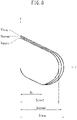
- disposing the shortening portion and the delaying portion enables the piston stroke to, in the forward operation mode, be set at a short stroke (Sshort in FIG. 8 ) and, in the reverse operation mode, to be set at a stroke that can be changed within a range from a normal stroke (Snormal in FIG. 8 ) to a long stroke (Slong in FIG. 8 ) .
- the abscissa S and the ordinate V represent the piston stroke and the piston velocity, respectively
- Vlong, Vnormal, and Vshort represent velocities at the time of strikes when in operation along the short stroke Sshort, the normal stroke Snormal, and the long stroke Slong, respectively
- S 0 represents a maximum velocity when the piston retracts from an impact point.
- the high pressure accumulator 400 and the low pressure accumulator 401 are arranged in the reverse operation circuit 101 and the forward operation circuit 102, respectively, in the first embodiment. While the high pressure accumulator 400 and the low pressure accumulator 401 use common constituent components, such as a pressure container and a diaphragm, setting values of pressure of a sealed gas are set at a high pressure and a low pressure for the high pressure accumulator 400 and the low pressure accumulator 401, respectively.
- the high pressure accumulator 400 absorbs shock and pulsation propagating through high pressure oil by accumulating the high pressure oil and, when the amount of oil becomes insufficient in the circuit, makes up the insufficiency in supply of the pressurized oil by discharging the accumulated pressurized oil.
- the low pressure accumulator 401 absorbs shock and pulsation propagating through low pressure oil by accumulating the low pressure oil.
- the forward operation mode when the forward operation mode is selected by switching the operation switching valve 105, pressure in the high pressure accumulator 400 and pressure in the low pressure accumulator 401 become low and high, respectively and, in particular, the low pressure accumulator 401, which is caused to accumulate high pressure oil, may have a lack of performance.
- the forward operation mode causes the piston stroke to be shortened to a short stroke, shock and pulsation in the passages become relatively moderate. Therefore, there is no significant inconvenience in use of the low pressure accumulator 401.
- the third embodiment since a pair of the high pressure accumulator 400 and the low pressure accumulator 402 and a pair of the high pressure accumulator 403 and the low pressure accumulator 401 are disposed to the reverse operation circuit 101 and the forward operation circuit 102 side by side in such a way that the high pressure accumulators 400 and 403 are disposed on the switching valve mechanism 210 side, respectively, it becomes possible for the high pressure accumulators and the low pressure accumulators to achieve the original performance even when either the reverse operation mode or the forward operation mode is selected.
- Operational effects of accumulators used in a hydraulic striking device of this type include a "buffering action” for preventing equipment from being damaged by absorbing shock and pulsation propagating through pressurized oil in a circuit and an "energy accumulation action” for accumulating pressurized oil when the amount of oil in the circuit is excessive with respect to the amount of discharge from a pump and discharging accumulated pressurized oil when the amount of oil is insufficient.
- the accumulators converts kinetic energy of the piston 200 into striking energy by using pressurized oil as a medium and accumulating and discharging the pressurized oil.
- the fourth embodiment instead of converting kinetic energy of the piston 200 into striking energy by using pressurized oil as a medium, converts kinetic energy at the time of retraction of the piston 200 into striking energy by directly accumulating and discharging the kinetic energy in the gas chamber 411 of the back head 410.
- a basic concept of the present invention is to change striking characteristics by switching the high pressure circuit 103 and the low pressure circuit 104 in an interchanging manner.
- the high pressure accumulator 400 and the low pressure accumulator 401 are disposed to the high pressure circuit 103 and the low pressure circuit 104, respectively and there may occur a case where the respective accumulators cannot achieve the original performance thereof due to the circuit switching, the energy accumulation action by the back head 410 is suitable for the present invention because the circuit switching does not affect the energy accumulation action by the back head 410.
- the back head 410 as an alternative means to an accumulator, can buffer such shock and pulsation to some extent, effect of the buffering action by the back head 410 is limited when compared with an accumulator. For this reason, it is preferable to employ the fourth embodiment for a small-size hydraulic striking mechanism in which shock and pulsation in the pressurized oil in the circuit is relatively small.
- the fourth embodiment is preferable because omission of accumulators enables a hydraulic striking device to be miniaturized and the configuration thereof to be simplified.
- opening widths (sealing lengths) between the valve and the ports are used as a measure for creating a time difference between a valve advancing movement and a valve retracting movement
- opening widths (sealing lengths) between the valve and the ports are used as a measure for creating a time difference between a valve advancing movement and a valve retracting movement
- the first embodiment and the fourth embodiment may be embodied at the same time, that is, accumulators may be respectively disposed to the high pressure circuit and the low pressure circuit and, in conjunction therewith, a back head equipped with a gas chamber is disposed to a rear portion of the cylinder.
Landscapes
- Engineering & Computer Science (AREA)
- Physics & Mathematics (AREA)
- Fluid Mechanics (AREA)
- Mechanical Engineering (AREA)
- Automation & Control Theory (AREA)
- Percussive Tools And Related Accessories (AREA)
- Fluid-Pressure Circuits (AREA)
- Electrophonic Musical Instruments (AREA)
Claims (5)
- Dispositif de percussion hydraulique comprenant : un vérin (100) ; un piston (200) monté coulissant à l'intérieur du vérin (100) ; une chambre avant de piston (110) et une chambre arrière de piston (111) définies entre une surface périphérique extérieure du piston (200) et une surface périphérique intérieure du vérin (100) et agencées séparées l'une de l'autre dans des directions axiales avant et arrière ; et un mécanisme de soupape de commutation (210) configuré pour commuter la chambre avant de piston (110) et la chambre arrière de piston (111) vers un état haute pression et un état basse pression d'une manière interchangeable, le piston (200) étant avancé et rétracté dans le vérin (100) pour percuter une tige de percussion, dans lequelle mécanisme de soupape de commutation (210) comprend une chambre de soupape (130) formée dans le vérin (100) d'une manière non concentrique avec le piston (200), une soupape (300) montée coulissante dans la chambre de soupape (130) et pour laquelle une partie de commutation haute/basse pression pour commuter la chambre avant de piston (110) et la chambre arrière de piston (111) vers un état haute pression et un état basse pression d'une manière interchangeable est formée, une partie de sollicitation de soupape configurée pour solliciter constamment la soupape (300) vers l'avant, et une partie de commande de soupape (137) configurée pour, lorsqu'une huile sous pression est fournie, déplacer la soupape (300) vers l'arrière contre une force de sollicitation par la partie de sollicitation de soupape,un circuit de fonctionnement inverse (101) et un circuit de fonctionnement direct (102) sont reliés au mécanisme de soupape de commutation (210), etla partie de sollicitation de soupape comprend une partie de sollicitation de fonctionnement inverse (123) configurée pour fonctionner lorsque le circuit de fonctionnement inverse (102) est relié au circuit haute pression (103) et une partie de sollicitation de fonctionnement direct (125) configurée pour fonctionner lorsque le circuit de fonctionnement direct (102) est relié au circuit haute pression (103),caractérisé en ce que les états de liaison du circuit de fonctionnement inverse (101) et du circuit de fonctionnement direct (102) à un circuit haute pression (103) et à un circuit basse pression (104) sont interchangeables au moyen d'une soupape de commutation de fonctionnement (105),le dispositif de percussion hydraulique est configuré, par le fonctionnement de la soupape de commutation de fonctionnement (105), de manière à pouvoir être sélectionné entre un mode de fonctionnement inverse dans lequel la soupape (300) et le piston (200) sont actionnés dans des phases opposées et un mode de fonctionnement direct dans lequel la soupape (300) et le piston (200) sont actionnés dans la même phase, etune partie de raccourcissement est disposée sur la partie de commutation haute/basse pression, pour réduire le temps requis pour une opération de commutation haute/basse pression dans la chambre avant de piston (110) et la chambre arrière de piston (111) en association avec la rétraction de la soupape (300) pour être plus court que le temps requis pour une opération de commutation haute/basse pression dans la chambre avant de piston (110) et la chambre arrière de piston (111) en association avec l'avancement de la soupape (300).
- Dispositif de percussion hydraulique selon la revendication 1, dans lequel la partie de raccourcissement est une différence entre une largeur d'ouverture d'un orifice qui est fermé par la soupape (300) au moment de l'avancement de la soupape (300) et une largeur d'ouverture d'un orifice qui est fermé par la soupape (300) au moment de rétraction de la soupape (300).
- Dispositif de percussion hydraulique selon la revendication 1 ou 2, dans lequel la partie de commande de soupape (137) comprend une partie de retard comprenant un étranglement configuré pour ne fournir aucune restriction lorsqu'une huile sous pression est fournie et pour régler un débit lorsqu'une huile sous pression est déchargée.
- Dispositif de percussion hydraulique selon l'une quelconque des revendications 1 à 3, comprenant un accumulateur haute pression (400, 403) disposé sur le circuit de fonctionnement inverse et un accumulateur basse pression (401, 402) disposé sur le circuit de fonctionnement direct.
- Dispositif de percussion hydraulique selon l'une quelconque des revendications 1 à 3 comprenant des paires d'un accumulateur haute pression (400, 403) et d'un accumulateur basse pression (401, 402) disposés respectivement sur le circuit de fonctionnement inverse (101) et le circuit de fonctionnement direct (102), dans lequel
chacune des paires de l'accumulateur haute pression (400, 403) et de l'accumulateur basse pression (401, 402) est disposée côte à côte de sorte que l'accumulateur haute pression (400, 403) soit disposé sur le côté de mécanisme de soupape de commutation (210).
Applications Claiming Priority (2)
| Application Number | Priority Date | Filing Date | Title |
|---|---|---|---|
| JP2016168995 | 2016-08-31 | ||
| PCT/JP2017/029752 WO2018043175A1 (fr) | 2016-08-31 | 2017-08-21 | Dispositif de percussion hydraulique |
Publications (3)
| Publication Number | Publication Date |
|---|---|
| EP3508308A1 EP3508308A1 (fr) | 2019-07-10 |
| EP3508308A4 EP3508308A4 (fr) | 2019-09-04 |
| EP3508308B1 true EP3508308B1 (fr) | 2022-08-17 |
Family
ID=61301633
Family Applications (1)
| Application Number | Title | Priority Date | Filing Date |
|---|---|---|---|
| EP17846183.6A Active EP3508308B1 (fr) | 2016-08-31 | 2017-08-21 | Dispositif de percussion hydraulique |
Country Status (7)
| Country | Link |
|---|---|
| US (1) | US11084155B2 (fr) |
| EP (1) | EP3508308B1 (fr) |
| JP (1) | JP6588651B2 (fr) |
| KR (1) | KR102163473B1 (fr) |
| CN (1) | CN109641347B (fr) |
| ES (1) | ES2927066T3 (fr) |
| WO (1) | WO2018043175A1 (fr) |
Families Citing this family (2)
| Publication number | Priority date | Publication date | Assignee | Title |
|---|---|---|---|---|
| WO2018043175A1 (fr) * | 2016-08-31 | 2018-03-08 | 古河ロックドリル株式会社 | Dispositif de percussion hydraulique |
| JP7359584B2 (ja) * | 2019-07-23 | 2023-10-11 | 古河ロックドリル株式会社 | 液圧式打撃装置 |
Family Cites Families (40)
| Publication number | Priority date | Publication date | Assignee | Title |
|---|---|---|---|---|
| GB171944A (en) * | 1921-04-20 | 1921-12-01 | George Henry Turton Rayner | Improvements in or relating to valve apparatus for rock drills and like fluid pressure operated tools |
| DE1703061C3 (de) * | 1968-03-27 | 1974-02-14 | Fried. Krupp Gmbh, 4300 Essen | Hydraulisch betriebener Schubkolbenmotor |
| JPS4912785B1 (fr) | 1969-11-19 | 1974-03-27 | ||
| US3759335A (en) * | 1971-12-30 | 1973-09-18 | Bell Lab Inc | Mole hammer-cycle control |
| US4006783A (en) * | 1975-03-17 | 1977-02-08 | Linden-Alimak Ab | Hydraulic operated rock drilling apparatus |
| JPS51111401A (en) * | 1975-03-26 | 1976-10-01 | Linden Alimak Ab | Device for drilling rock |
| US4314612A (en) * | 1978-07-20 | 1982-02-09 | Battelle Development Corporation | Hydraulic linear impact tool |
| DE3443542A1 (de) * | 1984-11-29 | 1986-06-05 | Fried. Krupp Gmbh, 4300 Essen | Hydraulische schlagvorrichtung |
| WO1987003925A1 (fr) * | 1985-12-23 | 1987-07-02 | Spetsialnoe Konstruktorskoe Bjuro Gidroimpulsnoi T | Dispositif de percussion |
| FR2618092B1 (fr) * | 1987-07-17 | 1989-11-10 | Montabert Ets | Distributeur hydraulique pour appareil a percussions mu par un fluide incompressible sous pression |
| DE3913866A1 (de) * | 1989-04-27 | 1990-10-31 | Krupp Maschinentechnik | Hydraulisches schlagwerk |
| JPH02298477A (ja) * | 1989-05-10 | 1990-12-10 | Mazda Motor Corp | 打撃工具 |
| FR2647870B1 (fr) * | 1989-06-06 | 1991-09-06 | Eimco Secoma | Appareil de percussion hydraulique avec dispositif d'amortissement des ondes de choc en retour |
| DE4027021A1 (de) * | 1990-08-27 | 1992-03-05 | Krupp Maschinentechnik | Hydraulisch betriebene schlagdrehbohrvorrichtung, insbesondere zum ankerlochbohren |
| SE470408C (sv) * | 1992-07-07 | 1997-08-04 | Atlas Copco Rock Drills Ab | Slagverk |
| ATE202963T1 (de) * | 1994-02-19 | 2001-07-15 | Klemm Guenter | Hydraulischer schlaghammer |
| AT407280B (de) | 1995-04-27 | 2001-02-26 | Boehler Pneumatik Internat Gmb | Einrichtung zum verstellen des hubes von fluidgesteuerten schlageinrichtungen |
| FI104961B (fi) * | 1996-07-19 | 2000-05-15 | Sandvik Tamrock Oy | Painenestekäyttöinen iskuvasara |
| JP3817617B2 (ja) * | 1999-05-10 | 2006-09-06 | 新日本製鐵株式会社 | さく孔装置 |
| FI20010976A (fi) * | 2001-05-09 | 2002-11-10 | Sandvik Tamrock Oy | Menetelmä iskulaitteen työkierron ohjaamiseksi ja iskulaite |
| JP3967182B2 (ja) * | 2002-04-17 | 2007-08-29 | 古河機械金属株式会社 | 液圧式打撃装置のストローク調整機構 |
| JP4488694B2 (ja) * | 2003-06-25 | 2010-06-23 | 甲南電機株式会社 | 液圧式打撃装置 |
| JP2005177899A (ja) * | 2003-12-17 | 2005-07-07 | Konan Electric Co Ltd | 液圧式打撃装置 |
| SE528745C2 (sv) * | 2005-06-22 | 2007-02-06 | Atlas Copco Rock Drills Ab | Ventilanordning för slagverk och slagverk för bergborrmaskin |
| SE529615C2 (sv) * | 2006-02-20 | 2007-10-09 | Atlas Copco Rock Drills Ab | Slagverk och bergborrmaskin samt förfarande för att styra slagkolvens slaglängd |
| JP4912785B2 (ja) | 2006-08-03 | 2012-04-11 | 古河ロックドリル株式会社 | 液圧式打撃装置 |
| SE530524C2 (sv) * | 2006-09-13 | 2008-07-01 | Atlas Copco Rock Drills Ab | Slagverk, bergborrmaskin inkluderande ett dylikt slagverk och förfarande för styrning av ett slagverk |
| SE530885C2 (sv) * | 2007-02-23 | 2008-10-07 | Atlas Copco Rock Drills Ab | Förfarande vid slagverk, slagverk och bergborrmaskin |
| FI123634B (fi) * | 2007-10-05 | 2013-08-30 | Sandvik Mining & Constr Oy | Kallionrikkomislaite, suojaventtiili sekä menetelmä kallionrikkomislaitteen käyttämiseksi |
| AU2011301130A1 (en) * | 2010-09-10 | 2013-03-07 | Rockdrill Services Australia Pty Ltd | Improved rock drill |
| FR2983760B1 (fr) * | 2011-12-09 | 2014-08-15 | Montabert Roger | Procede de commutation de la course de frappe d'un piston de frappe d’un appareil a percussions |
| KR102069042B1 (ko) * | 2013-12-18 | 2020-02-11 | 니폰 뉴매틱 고교 가부시키가이샤 | 충격구동 공구 |
| EP3928927A1 (fr) * | 2014-01-30 | 2021-12-29 | Furukawa Rock Drill Co., Ltd. | Dispositif de percussion hydraulique |
| WO2015115106A1 (fr) * | 2014-01-31 | 2015-08-06 | 古河ロックドリル株式会社 | Dispositif de martelage hydraulique |
| US9701003B2 (en) * | 2014-05-23 | 2017-07-11 | Caterpillar Inc. | Hydraulic hammer having delayed automatic shutoff |
| DE102014108849B9 (de) * | 2014-06-25 | 2022-12-22 | Construction Tools Gmbh | Drucküberwachungsvorrichtung |
| FR3027543B1 (fr) * | 2014-10-28 | 2016-12-23 | Montabert Roger | Appareil a percussions |
| US20160199969A1 (en) * | 2015-01-12 | 2016-07-14 | Caterpillar Inc. | Hydraulic hammer having variable stroke control |
| FR3044572B1 (fr) * | 2015-12-02 | 2017-12-29 | Montabert Roger | Dispositif brise roches |
| WO2018043175A1 (fr) * | 2016-08-31 | 2018-03-08 | 古河ロックドリル株式会社 | Dispositif de percussion hydraulique |
-
2017
- 2017-08-21 WO PCT/JP2017/029752 patent/WO2018043175A1/fr unknown
- 2017-08-21 CN CN201780052007.XA patent/CN109641347B/zh active Active
- 2017-08-21 JP JP2018537137A patent/JP6588651B2/ja active Active
- 2017-08-21 KR KR1020197005780A patent/KR102163473B1/ko active IP Right Grant
- 2017-08-21 ES ES17846183T patent/ES2927066T3/es active Active
- 2017-08-21 US US16/329,160 patent/US11084155B2/en active Active
- 2017-08-21 EP EP17846183.6A patent/EP3508308B1/fr active Active
Also Published As
| Publication number | Publication date |
|---|---|
| ES2927066T3 (es) | 2022-11-02 |
| JPWO2018043175A1 (ja) | 2019-02-21 |
| EP3508308A4 (fr) | 2019-09-04 |
| EP3508308A1 (fr) | 2019-07-10 |
| US20190224835A1 (en) | 2019-07-25 |
| KR20190034290A (ko) | 2019-04-01 |
| CN109641347A (zh) | 2019-04-16 |
| CN109641347B (zh) | 2021-08-31 |
| JP6588651B2 (ja) | 2019-10-09 |
| KR102163473B1 (ko) | 2020-10-08 |
| WO2018043175A1 (fr) | 2018-03-08 |
| US11084155B2 (en) | 2021-08-10 |
Similar Documents
| Publication | Publication Date | Title |
|---|---|---|
| EP3100829B1 (fr) | Dispositif de martelage hydraulique | |
| EP3508308B1 (fr) | Dispositif de percussion hydraulique | |
| KR102033235B1 (ko) | 액압식 타격장치 | |
| EP3659752B1 (fr) | Dispositif de percussion hydraulique | |
| JP6792034B2 (ja) | 油圧打撃装置 | |
| EP2718064B1 (fr) | Appareil de percussion et de concassage de roches et méthode de contrôle du dispositif de percussion | |
| JP4912785B2 (ja) | 液圧式打撃装置 | |
| JP4488694B2 (ja) | 液圧式打撃装置 | |
| JP6495672B2 (ja) | 液圧式打撃装置、並びにバルブタイミングの切換方法およびバルブポートの設定方法 | |
| JP6470058B2 (ja) | 液圧式打撃装置 | |
| JPS6362355B2 (fr) | ||
| JP6757682B2 (ja) | 液圧式打撃装置 | |
| JPH06328371A (ja) | 流体作動衝撃ハンマー | |
| JPH05190B2 (fr) | ||
| JPS63180482A (ja) | 液圧式打撃装置の空打切換機構 |
Legal Events
| Date | Code | Title | Description |
|---|---|---|---|
| STAA | Information on the status of an ep patent application or granted ep patent |
Free format text: STATUS: THE INTERNATIONAL PUBLICATION HAS BEEN MADE |
|
| PUAI | Public reference made under article 153(3) epc to a published international application that has entered the european phase |
Free format text: ORIGINAL CODE: 0009012 |
|
| STAA | Information on the status of an ep patent application or granted ep patent |
Free format text: STATUS: REQUEST FOR EXAMINATION WAS MADE |
|
| 17P | Request for examination filed |
Effective date: 20190228 |
|
| AK | Designated contracting states |
Kind code of ref document: A1 Designated state(s): AL AT BE BG CH CY CZ DE DK EE ES FI FR GB GR HR HU IE IS IT LI LT LU LV MC MK MT NL NO PL PT RO RS SE SI SK SM TR |
|
| AX | Request for extension of the european patent |
Extension state: BA ME |
|
| REG | Reference to a national code |
Ref country code: DE Ref legal event code: R079 Ref document number: 602017060828 Country of ref document: DE Free format text: PREVIOUS MAIN CLASS: B25D0009260000 Ipc: B25D0009180000 |
|
| A4 | Supplementary search report drawn up and despatched |
Effective date: 20190802 |
|
| RIC1 | Information provided on ipc code assigned before grant |
Ipc: B25D 9/18 20060101AFI20190729BHEP Ipc: B25D 9/26 20060101ALI20190729BHEP Ipc: B25D 9/14 20060101ALI20190729BHEP Ipc: B25D 9/20 20060101ALI20190729BHEP |
|
| DAV | Request for validation of the european patent (deleted) | ||
| DAX | Request for extension of the european patent (deleted) | ||
| GRAP | Despatch of communication of intention to grant a patent |
Free format text: ORIGINAL CODE: EPIDOSNIGR1 |
|
| STAA | Information on the status of an ep patent application or granted ep patent |
Free format text: STATUS: GRANT OF PATENT IS INTENDED |
|
| INTG | Intention to grant announced |
Effective date: 20220318 |
|
| GRAS | Grant fee paid |
Free format text: ORIGINAL CODE: EPIDOSNIGR3 |
|
| RAP3 | Party data changed (applicant data changed or rights of an application transferred) |
Owner name: FURUKAWA ROCK DRILL CO., LTD. |
|
| GRAA | (expected) grant |
Free format text: ORIGINAL CODE: 0009210 |
|
| STAA | Information on the status of an ep patent application or granted ep patent |
Free format text: STATUS: THE PATENT HAS BEEN GRANTED |
|
| AK | Designated contracting states |
Kind code of ref document: B1 Designated state(s): AL AT BE BG CH CY CZ DE DK EE ES FI FR GB GR HR HU IE IS IT LI LT LU LV MC MK MT NL NO PL PT RO RS SE SI SK SM TR |
|
| REG | Reference to a national code |
Ref country code: CH Ref legal event code: EP |
|
| REG | Reference to a national code |
Ref country code: DE Ref legal event code: R096 Ref document number: 602017060828 Country of ref document: DE |
|
| REG | Reference to a national code |
Ref country code: IE Ref legal event code: FG4D |
|
| REG | Reference to a national code |
Ref country code: AT Ref legal event code: REF Ref document number: 1511870 Country of ref document: AT Kind code of ref document: T Effective date: 20220915 |
|
| REG | Reference to a national code |
Ref country code: ES Ref legal event code: FG2A Ref document number: 2927066 Country of ref document: ES Kind code of ref document: T3 Effective date: 20221102 |
|
| REG | Reference to a national code |
Ref country code: SE Ref legal event code: TRGR |
|
| REG | Reference to a national code |
Ref country code: NL Ref legal event code: MP Effective date: 20220817 |
|
| REG | Reference to a national code |
Ref country code: LT Ref legal event code: MG9D |
|
| PG25 | Lapsed in a contracting state [announced via postgrant information from national office to epo] |
Ref country code: RS Free format text: LAPSE BECAUSE OF FAILURE TO SUBMIT A TRANSLATION OF THE DESCRIPTION OR TO PAY THE FEE WITHIN THE PRESCRIBED TIME-LIMIT Effective date: 20220817 Ref country code: PT Free format text: LAPSE BECAUSE OF FAILURE TO SUBMIT A TRANSLATION OF THE DESCRIPTION OR TO PAY THE FEE WITHIN THE PRESCRIBED TIME-LIMIT Effective date: 20221219 Ref country code: NO Free format text: LAPSE BECAUSE OF FAILURE TO SUBMIT A TRANSLATION OF THE DESCRIPTION OR TO PAY THE FEE WITHIN THE PRESCRIBED TIME-LIMIT Effective date: 20221117 Ref country code: NL Free format text: LAPSE BECAUSE OF FAILURE TO SUBMIT A TRANSLATION OF THE DESCRIPTION OR TO PAY THE FEE WITHIN THE PRESCRIBED TIME-LIMIT Effective date: 20220817 Ref country code: LV Free format text: LAPSE BECAUSE OF FAILURE TO SUBMIT A TRANSLATION OF THE DESCRIPTION OR TO PAY THE FEE WITHIN THE PRESCRIBED TIME-LIMIT Effective date: 20220817 Ref country code: LT Free format text: LAPSE BECAUSE OF FAILURE TO SUBMIT A TRANSLATION OF THE DESCRIPTION OR TO PAY THE FEE WITHIN THE PRESCRIBED TIME-LIMIT Effective date: 20220817 |
|
| REG | Reference to a national code |
Ref country code: AT Ref legal event code: MK05 Ref document number: 1511870 Country of ref document: AT Kind code of ref document: T Effective date: 20220817 |
|
| PG25 | Lapsed in a contracting state [announced via postgrant information from national office to epo] |
Ref country code: PL Free format text: LAPSE BECAUSE OF FAILURE TO SUBMIT A TRANSLATION OF THE DESCRIPTION OR TO PAY THE FEE WITHIN THE PRESCRIBED TIME-LIMIT Effective date: 20220817 Ref country code: IS Free format text: LAPSE BECAUSE OF FAILURE TO SUBMIT A TRANSLATION OF THE DESCRIPTION OR TO PAY THE FEE WITHIN THE PRESCRIBED TIME-LIMIT Effective date: 20221217 Ref country code: HR Free format text: LAPSE BECAUSE OF FAILURE TO SUBMIT A TRANSLATION OF THE DESCRIPTION OR TO PAY THE FEE WITHIN THE PRESCRIBED TIME-LIMIT Effective date: 20220817 Ref country code: GR Free format text: LAPSE BECAUSE OF FAILURE TO SUBMIT A TRANSLATION OF THE DESCRIPTION OR TO PAY THE FEE WITHIN THE PRESCRIBED TIME-LIMIT Effective date: 20221118 |
|
| REG | Reference to a national code |
Ref country code: CH Ref legal event code: PL |
|
| PG25 | Lapsed in a contracting state [announced via postgrant information from national office to epo] |
Ref country code: SM Free format text: LAPSE BECAUSE OF FAILURE TO SUBMIT A TRANSLATION OF THE DESCRIPTION OR TO PAY THE FEE WITHIN THE PRESCRIBED TIME-LIMIT Effective date: 20220817 Ref country code: RO Free format text: LAPSE BECAUSE OF FAILURE TO SUBMIT A TRANSLATION OF THE DESCRIPTION OR TO PAY THE FEE WITHIN THE PRESCRIBED TIME-LIMIT Effective date: 20220817 Ref country code: LU Free format text: LAPSE BECAUSE OF NON-PAYMENT OF DUE FEES Effective date: 20220821 Ref country code: LI Free format text: LAPSE BECAUSE OF NON-PAYMENT OF DUE FEES Effective date: 20220831 Ref country code: DK Free format text: LAPSE BECAUSE OF FAILURE TO SUBMIT A TRANSLATION OF THE DESCRIPTION OR TO PAY THE FEE WITHIN THE PRESCRIBED TIME-LIMIT Effective date: 20220817 Ref country code: CZ Free format text: LAPSE BECAUSE OF FAILURE TO SUBMIT A TRANSLATION OF THE DESCRIPTION OR TO PAY THE FEE WITHIN THE PRESCRIBED TIME-LIMIT Effective date: 20220817 Ref country code: CH Free format text: LAPSE BECAUSE OF NON-PAYMENT OF DUE FEES Effective date: 20220831 Ref country code: AT Free format text: LAPSE BECAUSE OF FAILURE TO SUBMIT A TRANSLATION OF THE DESCRIPTION OR TO PAY THE FEE WITHIN THE PRESCRIBED TIME-LIMIT Effective date: 20220817 |
|
| REG | Reference to a national code |
Ref country code: BE Ref legal event code: MM Effective date: 20220831 |
|
| REG | Reference to a national code |
Ref country code: DE Ref legal event code: R097 Ref document number: 602017060828 Country of ref document: DE |
|
| PG25 | Lapsed in a contracting state [announced via postgrant information from national office to epo] |
Ref country code: SK Free format text: LAPSE BECAUSE OF FAILURE TO SUBMIT A TRANSLATION OF THE DESCRIPTION OR TO PAY THE FEE WITHIN THE PRESCRIBED TIME-LIMIT Effective date: 20220817 Ref country code: MC Free format text: LAPSE BECAUSE OF FAILURE TO SUBMIT A TRANSLATION OF THE DESCRIPTION OR TO PAY THE FEE WITHIN THE PRESCRIBED TIME-LIMIT Effective date: 20220817 Ref country code: EE Free format text: LAPSE BECAUSE OF FAILURE TO SUBMIT A TRANSLATION OF THE DESCRIPTION OR TO PAY THE FEE WITHIN THE PRESCRIBED TIME-LIMIT Effective date: 20220817 |
|
| P01 | Opt-out of the competence of the unified patent court (upc) registered |
Effective date: 20230515 |
|
| PLBE | No opposition filed within time limit |
Free format text: ORIGINAL CODE: 0009261 |
|
| STAA | Information on the status of an ep patent application or granted ep patent |
Free format text: STATUS: NO OPPOSITION FILED WITHIN TIME LIMIT |
|
| PG25 | Lapsed in a contracting state [announced via postgrant information from national office to epo] |
Ref country code: AL Free format text: LAPSE BECAUSE OF FAILURE TO SUBMIT A TRANSLATION OF THE DESCRIPTION OR TO PAY THE FEE WITHIN THE PRESCRIBED TIME-LIMIT Effective date: 20220817 |
|
| 26N | No opposition filed |
Effective date: 20230519 |
|
| GBPC | Gb: european patent ceased through non-payment of renewal fee |
Effective date: 20221117 |
|
| PG25 | Lapsed in a contracting state [announced via postgrant information from national office to epo] |
Ref country code: IE Free format text: LAPSE BECAUSE OF NON-PAYMENT OF DUE FEES Effective date: 20220821 |
|
| PG25 | Lapsed in a contracting state [announced via postgrant information from national office to epo] |
Ref country code: SI Free format text: LAPSE BECAUSE OF FAILURE TO SUBMIT A TRANSLATION OF THE DESCRIPTION OR TO PAY THE FEE WITHIN THE PRESCRIBED TIME-LIMIT Effective date: 20220817 |
|
| PG25 | Lapsed in a contracting state [announced via postgrant information from national office to epo] |
Ref country code: BE Free format text: LAPSE BECAUSE OF NON-PAYMENT OF DUE FEES Effective date: 20220831 |
|
| PG25 | Lapsed in a contracting state [announced via postgrant information from national office to epo] |
Ref country code: GB Free format text: LAPSE BECAUSE OF NON-PAYMENT OF DUE FEES Effective date: 20221117 |
|
| PGFP | Annual fee paid to national office [announced via postgrant information from national office to epo] |
Ref country code: IT Payment date: 20230711 Year of fee payment: 7 Ref country code: FI Payment date: 20230816 Year of fee payment: 7 Ref country code: ES Payment date: 20230901 Year of fee payment: 7 |
|
| PGFP | Annual fee paid to national office [announced via postgrant information from national office to epo] |
Ref country code: SE Payment date: 20230630 Year of fee payment: 7 Ref country code: FR Payment date: 20230703 Year of fee payment: 7 Ref country code: DE Payment date: 20230627 Year of fee payment: 7 |
|
| PG25 | Lapsed in a contracting state [announced via postgrant information from national office to epo] |
Ref country code: HU Free format text: LAPSE BECAUSE OF FAILURE TO SUBMIT A TRANSLATION OF THE DESCRIPTION OR TO PAY THE FEE WITHIN THE PRESCRIBED TIME-LIMIT; INVALID AB INITIO Effective date: 20170821 |
|
| PG25 | Lapsed in a contracting state [announced via postgrant information from national office to epo] |
Ref country code: CY Free format text: LAPSE BECAUSE OF FAILURE TO SUBMIT A TRANSLATION OF THE DESCRIPTION OR TO PAY THE FEE WITHIN THE PRESCRIBED TIME-LIMIT Effective date: 20220817 |
|
| PG25 | Lapsed in a contracting state [announced via postgrant information from national office to epo] |
Ref country code: MK Free format text: LAPSE BECAUSE OF FAILURE TO SUBMIT A TRANSLATION OF THE DESCRIPTION OR TO PAY THE FEE WITHIN THE PRESCRIBED TIME-LIMIT Effective date: 20220817 |
|
| PG25 | Lapsed in a contracting state [announced via postgrant information from national office to epo] |
Ref country code: TR Free format text: LAPSE BECAUSE OF FAILURE TO SUBMIT A TRANSLATION OF THE DESCRIPTION OR TO PAY THE FEE WITHIN THE PRESCRIBED TIME-LIMIT Effective date: 20220817 |
|
| PG25 | Lapsed in a contracting state [announced via postgrant information from national office to epo] |
Ref country code: BG Free format text: LAPSE BECAUSE OF FAILURE TO SUBMIT A TRANSLATION OF THE DESCRIPTION OR TO PAY THE FEE WITHIN THE PRESCRIBED TIME-LIMIT Effective date: 20220817 |