EP3506979B1 - Dispositif d'électrode pour surveiller l'activité cérébrale chez un sujet - Google Patents
Dispositif d'électrode pour surveiller l'activité cérébrale chez un sujet Download PDFInfo
- Publication number
- EP3506979B1 EP3506979B1 EP17844694.4A EP17844694A EP3506979B1 EP 3506979 B1 EP3506979 B1 EP 3506979B1 EP 17844694 A EP17844694 A EP 17844694A EP 3506979 B1 EP3506979 B1 EP 3506979B1
- Authority
- EP
- European Patent Office
- Prior art keywords
- implantable body
- electrode
- electrodes
- reinforcement device
- electrode device
- Prior art date
- Legal status (The legal status is an assumption and is not a legal conclusion. Google has not performed a legal analysis and makes no representation as to the accuracy of the status listed.)
- Active
Links
- 238000012544 monitoring process Methods 0.000 title claims description 10
- 230000007177 brain activity Effects 0.000 title claims description 7
- 230000002787 reinforcement Effects 0.000 claims description 84
- 239000013536 elastomeric material Substances 0.000 claims description 26
- 210000004556 brain Anatomy 0.000 claims description 9
- 210000003128 head Anatomy 0.000 claims description 8
- 210000004761 scalp Anatomy 0.000 claims description 6
- 239000004020 conductor Substances 0.000 claims description 5
- 239000000835 fiber Substances 0.000 claims description 5
- 230000001419 dependent effect Effects 0.000 claims 1
- 238000012545 processing Methods 0.000 description 26
- 238000000034 method Methods 0.000 description 15
- 210000001519 tissue Anatomy 0.000 description 15
- 238000002513 implantation Methods 0.000 description 13
- 210000003625 skull Anatomy 0.000 description 12
- 230000000694 effects Effects 0.000 description 9
- 206010010904 Convulsion Diseases 0.000 description 8
- BASFCYQUMIYNBI-UHFFFAOYSA-N platinum Chemical compound [Pt] BASFCYQUMIYNBI-UHFFFAOYSA-N 0.000 description 7
- 230000008569 process Effects 0.000 description 7
- 230000001037 epileptic effect Effects 0.000 description 6
- 239000000463 material Substances 0.000 description 6
- 230000007246 mechanism Effects 0.000 description 5
- 238000004458 analytical method Methods 0.000 description 4
- 208000014674 injury Diseases 0.000 description 4
- 238000003780 insertion Methods 0.000 description 4
- 230000037431 insertion Effects 0.000 description 4
- 210000000653 nervous system Anatomy 0.000 description 4
- 238000003860 storage Methods 0.000 description 4
- 230000008733 trauma Effects 0.000 description 4
- 238000005452 bending Methods 0.000 description 3
- 238000004590 computer program Methods 0.000 description 3
- 206010015037 epilepsy Diseases 0.000 description 3
- 238000007917 intracranial administration Methods 0.000 description 3
- 230000000926 neurological effect Effects 0.000 description 3
- 241001465754 Metazoa Species 0.000 description 2
- 238000013500 data storage Methods 0.000 description 2
- 239000007943 implant Substances 0.000 description 2
- 238000004519 manufacturing process Methods 0.000 description 2
- 238000012986 modification Methods 0.000 description 2
- 230000004048 modification Effects 0.000 description 2
- 230000001537 neural effect Effects 0.000 description 2
- 229910052697 platinum Inorganic materials 0.000 description 2
- 230000004936 stimulating effect Effects 0.000 description 2
- 230000000638 stimulation Effects 0.000 description 2
- 238000005728 strengthening Methods 0.000 description 2
- 238000010146 3D printing Methods 0.000 description 1
- 208000014644 Brain disease Diseases 0.000 description 1
- 241001631457 Cannula Species 0.000 description 1
- 241000700201 Galea Species 0.000 description 1
- RTAQQCXQSZGOHL-UHFFFAOYSA-N Titanium Chemical compound [Ti] RTAQQCXQSZGOHL-UHFFFAOYSA-N 0.000 description 1
- 229920010741 Ultra High Molecular Weight Polyethylene (UHMWPE) Polymers 0.000 description 1
- 239000004699 Ultra-high molecular weight polyethylene Substances 0.000 description 1
- 230000000712 assembly Effects 0.000 description 1
- 238000000429 assembly Methods 0.000 description 1
- 230000008901 benefit Effects 0.000 description 1
- 239000002775 capsule Substances 0.000 description 1
- 239000000919 ceramic Substances 0.000 description 1
- 230000001055 chewing effect Effects 0.000 description 1
- 238000004891 communication Methods 0.000 description 1
- 238000011217 control strategy Methods 0.000 description 1
- 238000005520 cutting process Methods 0.000 description 1
- 238000007405 data analysis Methods 0.000 description 1
- 238000013461 design Methods 0.000 description 1
- 210000002249 digestive system Anatomy 0.000 description 1
- 239000013013 elastic material Substances 0.000 description 1
- 210000001613 integumentary system Anatomy 0.000 description 1
- 239000004761 kevlar Substances 0.000 description 1
- 210000004324 lymphatic system Anatomy 0.000 description 1
- 229920002529 medical grade silicone Polymers 0.000 description 1
- 229910052751 metal Inorganic materials 0.000 description 1
- 239000002184 metal Substances 0.000 description 1
- 210000003205 muscle Anatomy 0.000 description 1
- 230000008904 neural response Effects 0.000 description 1
- 239000012811 non-conductive material Substances 0.000 description 1
- 239000004033 plastic Substances 0.000 description 1
- 229920003023 plastic Polymers 0.000 description 1
- 229920001296 polysiloxane Polymers 0.000 description 1
- 230000000306 recurrent effect Effects 0.000 description 1
- 230000009467 reduction Effects 0.000 description 1
- 210000004994 reproductive system Anatomy 0.000 description 1
- 210000002345 respiratory system Anatomy 0.000 description 1
- 238000007493 shaping process Methods 0.000 description 1
- 230000006641 stabilisation Effects 0.000 description 1
- 229910000811 surgical stainless steel Inorganic materials 0.000 description 1
- 239000003826 tablet Substances 0.000 description 1
- MHSKRLJMQQNJNC-UHFFFAOYSA-N terephthalamide Chemical compound NC(=O)C1=CC=C(C(N)=O)C=C1 MHSKRLJMQQNJNC-UHFFFAOYSA-N 0.000 description 1
- 239000010936 titanium Substances 0.000 description 1
- 229910052719 titanium Inorganic materials 0.000 description 1
- 229920000785 ultra high molecular weight polyethylene Polymers 0.000 description 1
- 230000002485 urinary effect Effects 0.000 description 1
Images


Classifications
-
- A—HUMAN NECESSITIES
- A61—MEDICAL OR VETERINARY SCIENCE; HYGIENE
- A61B—DIAGNOSIS; SURGERY; IDENTIFICATION
- A61B5/00—Measuring for diagnostic purposes; Identification of persons
- A61B5/68—Arrangements of detecting, measuring or recording means, e.g. sensors, in relation to patient
- A61B5/6846—Arrangements of detecting, measuring or recording means, e.g. sensors, in relation to patient specially adapted to be brought in contact with an internal body part, i.e. invasive
-
- A—HUMAN NECESSITIES
- A61—MEDICAL OR VETERINARY SCIENCE; HYGIENE
- A61B—DIAGNOSIS; SURGERY; IDENTIFICATION
- A61B5/00—Measuring for diagnostic purposes; Identification of persons
- A61B5/24—Detecting, measuring or recording bioelectric or biomagnetic signals of the body or parts thereof
-
- A—HUMAN NECESSITIES
- A61—MEDICAL OR VETERINARY SCIENCE; HYGIENE
- A61B—DIAGNOSIS; SURGERY; IDENTIFICATION
- A61B5/00—Measuring for diagnostic purposes; Identification of persons
- A61B5/24—Detecting, measuring or recording bioelectric or biomagnetic signals of the body or parts thereof
- A61B5/316—Modalities, i.e. specific diagnostic methods
- A61B5/369—Electroencephalography [EEG]
-
- A—HUMAN NECESSITIES
- A61—MEDICAL OR VETERINARY SCIENCE; HYGIENE
- A61B—DIAGNOSIS; SURGERY; IDENTIFICATION
- A61B5/00—Measuring for diagnostic purposes; Identification of persons
- A61B5/40—Detecting, measuring or recording for evaluating the nervous system
- A61B5/4076—Diagnosing or monitoring particular conditions of the nervous system
- A61B5/4094—Diagnosing or monitoring seizure diseases, e.g. epilepsy
-
- A—HUMAN NECESSITIES
- A61—MEDICAL OR VETERINARY SCIENCE; HYGIENE
- A61B—DIAGNOSIS; SURGERY; IDENTIFICATION
- A61B5/00—Measuring for diagnostic purposes; Identification of persons
- A61B5/68—Arrangements of detecting, measuring or recording means, e.g. sensors, in relation to patient
- A61B5/6846—Arrangements of detecting, measuring or recording means, e.g. sensors, in relation to patient specially adapted to be brought in contact with an internal body part, i.e. invasive
- A61B5/6867—Arrangements of detecting, measuring or recording means, e.g. sensors, in relation to patient specially adapted to be brought in contact with an internal body part, i.e. invasive specially adapted to be attached or implanted in a specific body part
- A61B5/6868—Brain
-
- A—HUMAN NECESSITIES
- A61—MEDICAL OR VETERINARY SCIENCE; HYGIENE
- A61B—DIAGNOSIS; SURGERY; IDENTIFICATION
- A61B5/00—Measuring for diagnostic purposes; Identification of persons
- A61B5/68—Arrangements of detecting, measuring or recording means, e.g. sensors, in relation to patient
- A61B5/6846—Arrangements of detecting, measuring or recording means, e.g. sensors, in relation to patient specially adapted to be brought in contact with an internal body part, i.e. invasive
- A61B5/6879—Means for maintaining contact with the body
- A61B5/6882—Anchoring means
-
- A—HUMAN NECESSITIES
- A61—MEDICAL OR VETERINARY SCIENCE; HYGIENE
- A61N—ELECTROTHERAPY; MAGNETOTHERAPY; RADIATION THERAPY; ULTRASOUND THERAPY
- A61N1/00—Electrotherapy; Circuits therefor
- A61N1/02—Details
- A61N1/04—Electrodes
- A61N1/05—Electrodes for implantation or insertion into the body, e.g. heart electrode
- A61N1/0504—Subcutaneous electrodes
-
- A—HUMAN NECESSITIES
- A61—MEDICAL OR VETERINARY SCIENCE; HYGIENE
- A61N—ELECTROTHERAPY; MAGNETOTHERAPY; RADIATION THERAPY; ULTRASOUND THERAPY
- A61N1/00—Electrotherapy; Circuits therefor
- A61N1/02—Details
- A61N1/04—Electrodes
- A61N1/05—Electrodes for implantation or insertion into the body, e.g. heart electrode
- A61N1/0526—Head electrodes
- A61N1/0529—Electrodes for brain stimulation
-
- A—HUMAN NECESSITIES
- A61—MEDICAL OR VETERINARY SCIENCE; HYGIENE
- A61N—ELECTROTHERAPY; MAGNETOTHERAPY; RADIATION THERAPY; ULTRASOUND THERAPY
- A61N1/00—Electrotherapy; Circuits therefor
- A61N1/02—Details
- A61N1/04—Electrodes
- A61N1/05—Electrodes for implantation or insertion into the body, e.g. heart electrode
- A61N1/0551—Spinal or peripheral nerve electrodes
- A61N1/0553—Paddle shaped electrodes, e.g. for laminotomy
-
- A—HUMAN NECESSITIES
- A61—MEDICAL OR VETERINARY SCIENCE; HYGIENE
- A61N—ELECTROTHERAPY; MAGNETOTHERAPY; RADIATION THERAPY; ULTRASOUND THERAPY
- A61N1/00—Electrotherapy; Circuits therefor
- A61N1/02—Details
- A61N1/04—Electrodes
- A61N1/05—Electrodes for implantation or insertion into the body, e.g. heart electrode
- A61N1/0551—Spinal or peripheral nerve electrodes
- A61N1/0558—Anchoring or fixation means therefor
-
- A—HUMAN NECESSITIES
- A61—MEDICAL OR VETERINARY SCIENCE; HYGIENE
- A61N—ELECTROTHERAPY; MAGNETOTHERAPY; RADIATION THERAPY; ULTRASOUND THERAPY
- A61N1/00—Electrotherapy; Circuits therefor
- A61N1/18—Applying electric currents by contact electrodes
- A61N1/32—Applying electric currents by contact electrodes alternating or intermittent currents
- A61N1/36—Applying electric currents by contact electrodes alternating or intermittent currents for stimulation
- A61N1/3605—Implantable neurostimulators for stimulating central or peripheral nerve system
- A61N1/36057—Implantable neurostimulators for stimulating central or peripheral nerve system adapted for stimulating afferent nerves
-
- A—HUMAN NECESSITIES
- A61—MEDICAL OR VETERINARY SCIENCE; HYGIENE
- A61N—ELECTROTHERAPY; MAGNETOTHERAPY; RADIATION THERAPY; ULTRASOUND THERAPY
- A61N1/00—Electrotherapy; Circuits therefor
- A61N1/18—Applying electric currents by contact electrodes
- A61N1/32—Applying electric currents by contact electrodes alternating or intermittent currents
- A61N1/36—Applying electric currents by contact electrodes alternating or intermittent currents for stimulation
- A61N1/372—Arrangements in connection with the implantation of stimulators
- A61N1/375—Constructional arrangements, e.g. casings
- A61N1/37514—Brain implants
-
- A—HUMAN NECESSITIES
- A61—MEDICAL OR VETERINARY SCIENCE; HYGIENE
- A61B—DIAGNOSIS; SURGERY; IDENTIFICATION
- A61B2562/00—Details of sensors; Constructional details of sensor housings or probes; Accessories for sensors
- A61B2562/02—Details of sensors specially adapted for in-vivo measurements
- A61B2562/0209—Special features of electrodes classified in A61B5/24, A61B5/25, A61B5/283, A61B5/291, A61B5/296, A61B5/053
-
- A—HUMAN NECESSITIES
- A61—MEDICAL OR VETERINARY SCIENCE; HYGIENE
- A61B—DIAGNOSIS; SURGERY; IDENTIFICATION
- A61B2562/00—Details of sensors; Constructional details of sensor housings or probes; Accessories for sensors
- A61B2562/04—Arrangements of multiple sensors of the same type
- A61B2562/043—Arrangements of multiple sensors of the same type in a linear array
-
- A—HUMAN NECESSITIES
- A61—MEDICAL OR VETERINARY SCIENCE; HYGIENE
- A61N—ELECTROTHERAPY; MAGNETOTHERAPY; RADIATION THERAPY; ULTRASOUND THERAPY
- A61N1/00—Electrotherapy; Circuits therefor
- A61N1/18—Applying electric currents by contact electrodes
- A61N1/32—Applying electric currents by contact electrodes alternating or intermittent currents
- A61N1/36—Applying electric currents by contact electrodes alternating or intermittent currents for stimulation
- A61N1/3605—Implantable neurostimulators for stimulating central or peripheral nerve system
- A61N1/3606—Implantable neurostimulators for stimulating central or peripheral nerve system adapted for a particular treatment
- A61N1/36064—Epilepsy
Definitions
- the present disclosure relates to electrode devices to monitor and/or stimulate activity in a subject, including electrode devices for monitoring brain activity such as epileptic events.
- Epilepsy is considered the world's most common serious brain disorder, with an estimated 50 million sufferers worldwide and 2.4 million new cases occurring each year.
- Epilepsy is a condition of the brain characterized by epileptic seizures that vary from brief and barely detectable seizures to more conspicuous seizures in which a sufferer vigorously shakes. Epileptic seizures are unprovoked, recurrent and due to unexplained causes.
- EEG recordings typically performed using EEG electrodes attached to the outer surface of the scalp or via surgically implanted intracranial EEG electrodes.
- US 7,209,787B discloses a neurological control system for modulating activity of any component or structure comprising the entirety or portion of the nervous system, or any structure interfaced thereto, generally referred to herein as a "nervous system component.”
- the neurological control system generates neural modulation signals delivered to a nervous system component through one or more intracranial (IC) stimulating electrodes in accordance with treatment parameters.
- IC intracranial
- treatment parameters may be derived from a neural response to previously delivered neural modulation signals sensed by one or more sensors, each configured to sense a particular characteristic indicative of a neurological or psychiatric condition.
- US 2010/137928 A1 discloses further electrode devices.
- Embodiments of the present disclosure relate to the monitoring and/or stimulation of electrical activity in body tissue of a subject using an electrode device comprising a plurality of electrodes, one or more of which electrodes are implanted in the subject.
- Certain embodiments relate, for example, to electrode devices that are implanted in a head of a subject to monitor brain activity such as epileptic brain activity.
- electrode devices according to the present disclosure may be for implanting in a variety of different locations of the body where monitoring and/or stimulation of electrical activity is desired, including in or on one or more parts of the human or animal digestive system, respiratory system, urinary system, reproductive system, encrodine system, cardivacular system, lymphatic system, integumentary system and the nervous system.
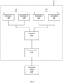
- an electrode device 100 comprising an elongate, implantable body 110 and a plurality of electrodes 120 positioned along the implantable body 110 in the length direction of the implantable body 110.
- a processing unit 130 is provided for processing electrical signals that can be sent to and/or received from the electrodes 120.
- An electrical amplifier 140 e.g., a pre-amp
- the electrical amplifier 140' may be integrated into the processing unit 130' of the electrode device 100', instead of being positioned in the implantable body 110'.
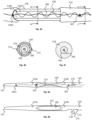
- Fig. 3a which shows a cross-section of a portion of the electrode device 100 adjacent one of the electrodes 120
- the electrodes 120 are electrically connected, e.g., to the amplifier 140 and processing unit 130, by an electrical connection 150 that extends through the implantable body 110.
- a reinforcement device 160 is also provided in the electrode device 100, which reinforcement device 160 extends through the implantable body 110 and limits the degree by which the length of the implantable body 110 can extend under tension.
- four electrodes 120 are provided that are spaced along the implantable body 110 between the amplifier 140 and a distal tip 111 of the implantable body 110.
- the distal tip 111 of the implantable body 110 is tapered.
- the four electrodes 120 are configured into two electrical pairs 121, 122 of electrodes, the two most distal electrodes 120 providing a first pair of electrodes 121 and the two most proximal electrodes 120 providing a second pair of electrodes 122.
- the electrodes 120 of the first pair 121 are spaced from each other at a distance x of about 40 to 60mm, e.g., about 50 mm (measured from centre-to-centre of the electrodes 120) and the electrodes 120 of the second pair 122 are also spaced from each other at a distance x of about 40 to 60mm, e.g., about 50 mm (measured from centre-to-centre of the electrodes 120).
- the first and second electrode pairs 121, 122 are spaced from each other at a distance y of about 30 to 50 mm, e.g., about 40 mm (measured from centre-to-centre of the electrodes of the two pairs that are adjacent each other).
- the amplifier 140 may comprise a battery and may amplify electrical signals sent between the electrodes 120 and the processing unit 130.
- the processing unit 130 may comprise a transceiver, an analogue to digital converter, and a processor to process data relating to electrical signals received from or transmitted to the electrodes 120.
- the processing unit 130 may include a memory to store the processed data.
- the processing unit 130 may be similar to a processing unit of a type commonly used with cochlear implants although other configurations are possible.
- the amplifier 140 e.g. when it is in line with the electrodes 120, may be made a medical grade titanium with ceramic feed through assemblies, for example.
- the data processed and stored by the processing unit 130 may be raw EEG data, for example.
- the EEG data may be transmitted wirelessly, or via a wire, to an external computing device 190 for analysing the data.
- the computing device 190 may analyse raw EEG signals to determine if a target event has occurred. Data regarding the event may be generated by the computing device 190 on the basis of the analysis.
- the computing device 190 may analyse brain activity signals to determine if a target event such as an epileptic event has occurred and data regarding the epileptic event may be generated by the computing device 190 on the basis of the analysis.
- the computing device 190 By carrying out data analysis externally to the electrode device 100, using the computing device 190, for example, there may be a reduction in power consumption within the electrode device 100, enabling the electrode device 100 to retain a smaller geometrical form. Moreover, the computing device 190 may have significantly higher processing power than would be possible with any processor included in the electrode device 100. The computing device 190 may run software that continuously records electrical data received from the electrode device 100.
- the processing unit 130 and/or computing device 190 can comprise a digital signal processor (DSP) and/or other components and/or software modules to carry out signal processing.
- DSP digital signal processor
- any processer that is used may comprise a number of control or processing modules for controlling one or more features of the present disclosure and may also include one or more storage elements, for storing desired data, e.g., raw or processed EEG data.
- the modules and storage elements can be implemented using one or more processing devices and one or more data storage units, which modules and/or storage devices may be at one location or distributed across multiple locations and interconnected by one or more communication links.
- Processing devices used in conjunction with the electrode device may include microprocessors, desktop computers, laptop computers, tablets, smartphones, personal digital assistants and other types of devices, including devices manufactured specifically for the purpose of carrying out methods according to the present disclosure.
- processing modules can be implemented by a computer program or program code comprising program instructions.
- the computer program instructions can include source code, object code, machine code or any other stored data that is operable to cause the processor to perform the steps described.
- the computer program can be written in any form of programming language, including compiled or interpreted languages and can be deployed in any form, including as a stand-alone program or as a module, component, subroutine or other unit suitable for use in a computing environment.
- the data storage device(s) may include suitable computer readable media such as volatile (e.g., RAM) and/or non-volatile (e.g., ROM, disk) memory or otherwise.
- the implantable body 110 has a round, e.g., substantially circular or ovate, cross-sectional profile.
- each of the electrodes 120 has a round, e.g., substantially circular or ovate, cross sectional profile.
- Each of the electrodes 120 extend circumferentially, completely around a portion of the implantable body 110.
- the electrodes 120 may be considered to have a 360 degree functionality.
- the round cross-sectional configuration can also provide for easier insertion of the implantable portions of the electrode device 100 to the target location and with less risk of damaging body tissue.
- the implantable body 110 can be used with insertion cannulas or sleeves and may have no sharp edges that might otherwise cause trauma to tissue.
- the implantable body 110 is formed of an elastomeric material such as medical grade silicone.
- Each electrode 120 comprises an annular portion of conductive material that extends circumferentially around a portion of the implantable body 110. More specifically, each electrode 120 comprises a hollow cylinder of conductive material that extends circumferentially around a portion of the implantable body 110 and, in particular, a portion of the elastomeric material of the implantable body 110.
- the electrodes 120 may be considered 'ring' electrodes.
- electrodes may be provided that do not extend completely around the circumference of a portion of the elastomeric material of the implantable body.
- one or more electrodes 410 are designed to extend part way around, and more particularly about three-quarters of the way around, the circumference of a portion of the elastomeric material of the implantable body 110'.
- one or more electrodes 420 are designed to extend part way around, and more particularly about half of the way around, the circumference of a portion of the elastomeric material of the implantable body 110".
- Figs. 16a to 16c in one embodiment, one or more electrodes 410 are designed to extend part way around, and more particularly about three-quarters of the way around, the circumference of a portion of the elastomeric material of the implantable body 110'.
- one or more electrodes 420 are designed to extend part way around, and more particularly about half of the way around, the circumference of a portion of the elastomeric material of the implantable body 110". In the embodiments of
- the electrodes 410, 420 are part-cylinders of conductive material, a quarter or half circumferential section of the cylinder being absent.
- the fabrication process for the electrode device may be simplified. It can allow elastomeric material and/or other features of the electrode device to be extended through the side of electrode without having to be fed through an end of the electrode for example.
- straps 112 are provided in this embodiment that extend across an outer surface of each electrode 120.
- two straps 112 are located on substantially opposite sides of each electrode 120 in a direction perpendicular to the direction of elongation of the implantable body 110.
- the straps 112 are connected between sections 113a, 113b of the implantable body 110 that are located on opposite sides of the electrodes 120 in the direction of elongation of implantable body, which sections 113a, 113b are referred to hereinafter as side sections.
- the straps 112 can prevent the side sections 113a, 113b from pulling or breaking away from the electrodes 120 when the implantable body 110 is placed under tension and/or is bent.
- the straps 112 are formed of the same elastomeric material as the side sections 113a, 113b.
- the straps 112 are integrally formed with the side sections 113a, 113b. From their connection points with the side sections 113a, 113b, the straps 112 decrease in width towards a central part of the each electrode 120, minimising the degree to which the straps 112 cover the surfaces of the electrodes 120 and ensuring that there remains a relatively large amount of electrode surface that is exposed around the circumference of the electrodes 120 to make electrical contact with adjacent body tissue.
- at least 75% of the outer electrode surface, at least 80%, at least 85% or at least 90% of the outer electrode surface may be exposed for electrical contact with tissue, for example.
- a different number of straps 112 may be employed, e.g., one, three, four or more straps 112. Where a greater number straps 112 are employed, the width of each strap 112 may be reduced.
- the straps 112 may be distributed evenly around the circumference of each electrode 120 or distributed in an uneven manner. Nevertheless, in some embodiments, the straps 112 may be omitted, ensuring that all of the outer electrode surface is exposed for electrical contact with tissue, around a circumference of the electrode 120.
- an electrode 430 is provided that has been modified to include portions of reduced diameter 431 at opposite ends of the electrode 430 in the direction of elongation of the electrode device.
- the reduced diameter is achieved by providing a reduced thickness to the wall of the cylinder that forms the electrode 430, although additionally or alternatively the reduced diameter portions may be formed through bending or shaping of conductive material forming the electrode or otherwise.
- the reduced diameter portions are configured to lie under, e.g. remain fully embedded in, the elastomeric material of the implantable body 110"'.
- Elastomeric material can extend both over the reduced diameter portions 431 and under the reduced diameter portions 431, trapping these portions of the electrodes within the implantable body and strengthening the engagement with the implantable body.
- Similar reduced diameter portions 411, 421 can be provided with electrodes that are formed as part-cylinders, e.g., as per the electrodes 410, 420 illustrated in Figs. 16a to 17c.
- one or more apertures 433 may be provided at the reduced diameter portions 431, or indeed any other portions of the electrodes that are directly connected to the elastomeric material.
- apertures 433 e.g. holes and/or slots, etc.
- elastomeric material may flow through the apertures 433, locking the electrodes 430 to the implantable body.
- Similar apertures may be introduced to the electrodes of other embodiments, such as those illustrated in Figs. 16 to 17c.
- the implantable body 110 is formed of an elastomeric material such as silicone.
- the elastomeric material allows the implantable body 110 to bend, flex and stretch such that the implantable body 110 can readily contort as it is routed to a target implantation position and can readily conform to the shape of the body tissue at the target implantation position.
- the use of elastomeric material also ensures that any risk of trauma to the subject is reduced during implantation or during subsequent use.
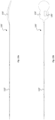
- the electrical connection 150 to the electrodes 120 comprises relatively fragile platinum wire conductive elements.
- the electrical connection 150 is provided with wave-like shape and, more specifically, a helical shape in this embodiment, although other non-linear shapes may be used.
- the helical shape, for example, of the electrical connection 150 enables the electrical connection 150 to stretch, flex and bend in conjunction with the implantable body. Bending, flexing and/or stretching of the implantable body 110 typically occurs during implantation of the implantable body in a subject and upon any removal of the implantable body 110 from the subject after use.
- a reinforcement device 160 is also provided in the electrode device 100, which reinforcement device 160 extends through the implantable body 110 and is provided to limit the degree by which the length of the implantable body 110 can extend under tension.
- the reinforcement device 160 can take the bulk of the strain placed on the electrode device 110 when the electrode device 100 is placed under tension.
- the reinforcement device 160 is provided in this embodiment by a fibre (e.g., strand, filament, cord or string) of material that is flexible and which has a high tensile strength.
- a fibre of ultra-high-molecular-weight polyethylene (UHMwPE), e.g., Dyneema TM is provided as the reinforcement device 160 in the present embodiment.
- the reinforcement device 160 extends through the implantable body 110 in the length direction of the implantable body 110 and is generally directly encased by the elastomeric material of the implantable body 110.
- the reinforcement device 160 may comprise a variety of different materials in addition to or as an alternative to UHMwPE.
- the reinforcement device may comprise other plastics and/or non-conductive material such as a poly-paraphenylene terephthalamide, e.g., Kevlar TM .
- a metal fibre or surgical steel may be used.
- the reinforcement device 160 Similar to the electrical connection 150, the reinforcement device 160 also has a wave-like shape and, more specifically, a helical shape in this embodiment, although other non-linear shapes may be used.
- the helical shape of the reinforcement device 160 is different from the helical shape of the electrical connection 150. For example, as evident from Figs. 3a to 3c , the helical shape of the reinforcement device 160 has a smaller diameter than the helical shape of the electrical connection 150. Moreover, the helical shape of the reinforcement device 160 has a greater pitch than the helical shape of the electrical connection 150.
- the elastomeric material of the implantable body will stretch, which in turns causes straightening of the helical shapes of both the electrical connection 150 and the reinforcement device 160, as evident from a comparison of Figs. 5a and 5b .
- the electrical connection 150 and the reinforcement device straighten 160 their lengths can be considered to increase in the direction of elongation of the implantable body 110.
- the lengths of each of the electrical connection 150 and the reinforcement device 160, in the direction of elongation of the implantable body 110 are extendible when the implantable body 110 is placed under tension.
- the maximum length of extension of the reinforcement device 160 is shorter than the maximum length of extension of the electrical connection 150. Therefore, when the implantable body 110 is placed under tension, the reinforcement device 160 will reach its maximum length of extension before the electrical connection 150 reaches its maximum length of extension (again as illustrated in Figs. 5a and 5b ). Indeed, the reinforcement device 160 can make it substantially impossible for the electrical connection 150 to reach its maximum length of extension.
- the reinforcement device 160 can reduce the likelihood that the electrical connection 150 will be damaged when the implantable body 110 is placed under tension. In contrast to the electrical connection 150, when the reinforcement device 160 reaches its maximum length of extension, its high tensile strength allows it to bear a significant amount of strain placed on the electrode device 100, preventing damage to the electrical connection 150 and other components of the electrode device 100.
- the implantable body 110 can be prone to damage or breakage when it is placed under tension.
- the elastomeric material of the implantable body 110 has a theoretical maximum length of extension in its direction of elongation when placed under tension, the maximum length of extension being the point at which the elastomeric material reaches its elastic limit.
- the maximum length of extension of the reinforcement device 160 is also shorter than the maximum length of extension of the implantable body 110.
- the reinforcement device 160 can make it substantially impossible for the implantable body 110 to reach its maximum length of extension. Since elastomeric material of the implantable body 110 can be relatively fragile and prone to breaking, particularly when placed under tension, and particularly when it reaches its elastic limit, the reinforcement device 160 can reduce the likelihood that the implantable body 110 will be damaged when it is placed under tension.
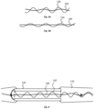
- the helical shapes of the reinforcement device 160 and the electrical connection 150 are provided in a concentric arrangement. Due to its smaller diameter, the reinforcement device 160 can locate radially inside of the electrical connection 150. In view of this positioning, the reinforcement device provides a form of strengthening core to the implantable body 110.
- the concentric arrangement can provide for increased strength and robustness while offering optimal surgical handling properties, with relatively low distortion of the implantable body 110 when placed under tension.
- the reinforcement device 160 is directly encased by the elastomeric material of the implantable body 110.
- the helically-shaped reinforcement device 160 therefore avoids contact with material other than the elastomeric material in this embodiment.
- the helically shaped reinforcement device is not entwined or intertwined with other strands or fibres, for example (e.g., as opposed to strands of a rope), ensuring that there is a substantial amount of give possible in relation to its helical shape.
- the helical shape can move to a straightened configuration under tension as a result, for example.
- the arrangement of the reinforcement device 160 is such that, when the implantable body 110 is placed under tension, the length of the reinforcement device 160 is extendible by about 20% of its length when the implantable body 110 is not under tension. Nevertheless, in embodiments of the present disclosure, a reinforcement device 160 may be used that is extendible by at least 5%, at least 10%, at least 15%, at least 20% or at least 25% or otherwise, of the length of the reinforcement device when the implantable body is not under tension.
- the maximum length of extension of the reinforcement device in the direction of elongation of the implantable body may be about 5%, about 10%, about 15%, about 20% or about 25% or otherwise of its length when the implantable body is not under tension.
- the reinforcement device 160 has a relatively uniform helical configuration along its length.
- the shape of the reinforcement device can be varied along its length.
- the reinforcement device can be straighter (e.g., by having a helical shape with smaller radius and/or greater pitch) adjacent the electrodes 120 in comparison to at other portions of the implantable body 110.
- stretching of the implantable body 110 may be reduced adjacent the electrodes 120, where there could otherwise be a greater risk of the electrodes 120 dislocating from the implantable body 110.
- This enhanced strain relief adjacent the electrodes 120 can be provided while still maintaining the ability of the reinforcement device 160, and therefore implantable body 110, to stretch to a desirable degree at other portions of the implantable body 110.
- the electrical connection 150 in this embodiment comprises relatively fragile platinum wire conductive elements. At least 4 platinum wires are provided in the electrical connection 150 to each connect to a respective one of the four electrodes 120. The wires are twisted together and electrically insulated from each other. Connection of a platinum wire of the electrical connection 150 to the most distal of the electrodes is illustrated in Fig. 3a . As can be seen, the wire is connected to an inner surface 1210 of the electrode 120, adjacent a distal end of the electrode 120, albeit other connection arrangements can be used.
- the reinforcement device 160 extends through the hollow centre of each of the electrodes 120.
- the reinforcement device 160 extends at least from the distal most electrode 120, and optionally from a region adjacent the distal tip 111 of the implantable body 110, to a position adjacent the amplifier 140.
- the reinforcement device 160 may also extend between the amplifier 140 and the processing unit 130.
- the reinforcement device 160 may extend from the distal tip 111 and/or the distal most electrode 120 of the implantable body 110 to the processing unit 130.
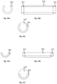
- a series of knots 161 are formed in the reinforcement device 160 along the length of the reinforcement device 160.
- a knot 161a can be formed at least at the distal end of the reinforcement device 160, adjacent the distal tip 111 of the implantable body 110, and/or knots 161 can be formed adjacent one or both sides of each electrode 120.
- the knots may alone provide resistance to movement of the reinforcement device 160 relative to the elastic material of the implantable body and/or may be used to fix (tie) the reinforcement device 160 to other features of the device 100.
- the reinforcement device 160 is fixed, via a knot 161b, to each electrode 120.
- the electrode 120 comprises an extension portion 1220 around which knots 161 of the reinforcement device 160 can be tied.
- the extension portion 1220 can include a loop or arm of material that extends across an open end of the hollow cylinder forming the electrode 120.
- Another example of a loop or arm, providing an extension portion 432 of an electrode 430 to which a reinforcement device 1600 is tied using a knot 1601, or is otherwise connected, is provided in the embodiment illustrated in Figs. 18a to 18c .
- Figs. 18a to 18c is another example of a loop or arm, providing an extension portion 432 of an electrode 430 to which a reinforcement device 1600 is tied using a knot 1601, or is otherwise connected, is provided in the embodiment illustrated in Figs. 18a to 18c .
- a conduit or eye 442 may be located within an electrode 440, e.g. within the hollow cylinder of the electrode 440, to which a the reinforcement device 1610 is tied, or is otherwise connected.
- a knot 1611 may be formed on one or both sides of the conduit or eye 442 to prevent relative axial movement between the reinforcement device 1610 and the electrode 440.
- the extension portion 432 or the conduit or eye 442 can be utilised with other embodiments of the electrodes, e.g. including those having a part-cylindrical shape as illustrated in Figs. 16a to 17c, for example.
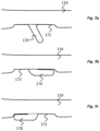
- the electrode device 100 comprises at least one anchor 170, and in this embodiment of plurality of anchors 170.
- the plurality of anchors 170 are positioned along a length of the implantable body 110, each adjacent a respective one of the electrodes 120.
- Each anchor 170 is configured to project radially outwardly from the implantable body 110 and specifically, in this embodiment, at an angle towards a proximal end of the implantable body 110.
- Each anchor 170 is in the form of a flattened appendage or fin with a rounded tip 171.
- the anchors 170 are designed to provide stabilisation to the electrode device 100 when it is in the implantation position.
- each anchor 170 When implanted, a tissue capsule can form around each anchor 170, securing the anchor 170 and therefore the implantable body 110 into place.
- the anchors 170 are between about 0.5 mm and 2 mm in length, e.g., about 1 mm or 1.5 mm in length.
- each anchor 170 is compressible.
- the anchors 170 are compressible (e.g., foldable) to reduce the degree by which the anchors 170 projects radially outwardly from the implantable body 110.
- a recess 172 is provided in a surface of the implantable body 110 adjacent each anchor 170.
- the anchor is compressible into the recess 172.
- the anchors 170 project from a bottom surface of the respective recess 172 and the recess extends on both proximal and distal sides of the anchor 170.
- the anchors 170 can be compressed into the respective recesses in either a proximal or distal direction, as illustrated in Figs. 7b and 7c .
- This has the advantage of allowing the anchors 170 to automatically move into a storage position in the recess 172 when pulled across a tissue surface or a surface of a implantation tool such as delivery device, in either of a proximal and a distal direction.
- the electrode device 100 of the present embodiment is configured for use in monitoring electrical activity in the brain and particularly for monitoring electrical activity relating to epileptic events in the brain.
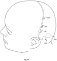
- the electrode device 100 is configured to be implanted at least partially in a subgaleal space between the scalp and the cranium. At least the electrodes 120 and adjacent portions of the implantable body 110 are located in the subgaleal space.
- FIG. 8 An illustration of the implantation location of the electrodes 120 is provided in Fig. 8 .
- the electrodes 120 locate in particular in a pocket between the galea aponeurotica and the pericranium.
- Fig. 9 when implanted, the first and second electrode pairs 121, 122 are located on respective sides of the midline 310 of the head 300 of the subject in a substantially symmetrical arrangement. The first and second electrode pairs 121, 122 therefore locate over the right and left hemispheres 306a, 306b of the brain, respectively.
- the first electrode pair 121 can be used to monitor electrical activity at right hemisphere 306a of the brain and the second electrode pair 121 can be used to monitor electrical activity at the left hemisphere of the brain 306b, or vice-versa.
- Independent electrical activity data may be recorded for each of the right and left hemispheres, e.g., for diagnostic purposes.
- the implantable body 110 of the electrode device is implanted in a medial-lateral direction over the cranium of the subject's head 180.
- the electrode pairs 121, 122 are positioned away from the subject's eyes and chewing muscles to avoid introduction of signal artifacts from these locations.
- a method of implanting the electrode device 100 according to an embodiment of the present disclosure is described further below with reference to Figs. 12a to 12d.
- the method employs a delivery device 200, as illustrated in Figs. 10a, 10b and 11 .
- the delivery device 200 can create a subgaleal pocket in which the electrode device 100 locates, and can assist with channelling of the electrode device 100 to this implantation location, i.e. into the subgaleal pocket. Slight modifications may be made to the method and associated delivery device when the electrode device is for use at other locations of the human or animal body.
- the delivery device 200 which may also be considered a "trocar", for example, comprises a cannula 210 that has a length sufficient to reach over the subject's skull between a first incision 301 that is located posteriorly of the temple on one side of the subject's head and a second incision 302 that is located posteriorly of the ear on the other side of the subject's head.
- the locations of the first and second incisions 301, 302 are illustrated in Figs. 12a and 12b , respectively, and the purpose of the incisions 301, 302 is described in more detail below.
- the delivery device 200 comprises a handle 220 that can be gripped by the surgeon to manipulate movement of the cannula 210 through the first incision 301 and over the subject's skull.
- the handle 220 is ergonomically shaped for comfort and is formed from two hollow shells that are fixed together, e.g., using screws.
- the handle design may be particularly suited for forming using 3D printing.
- the delivery device 200 also comprises a releasable inner member, and in this embodiment an inner filament 230, that extends through a central channel of the cannula 210 and has a distal tip 231 that is exposed at a distal end opening 211 of the cannula 210.
- the distal tip 231 of the filament 200 is pointed to provide a leading end of the delivery device 200 that can navigate or tunnel through, and open up a pocket between, tissue layers.
- the distal tip 231 is located distally of the distal end opening 211 of the cannula 210.
- the filament 230 extends from the distal end opening 211 of the cannula 210 to a location inside the handle 220.
- the cannula 210 comprises flexible material that is pre-curved in an S-shape.
- the pre-curved shape is designed to assist in tunnelling of the cannula 210 almost 150 to 180 degrees around the skull, while avoiding the need to make more than two incisions and to use multiple tunnelling trajectories, for example.
- the curvature of the cannula 210 may approximately match a curvature of the skull, for example.
- the cannula 210 has different flexibility properties along its length. In this embodiment, the different flexibility is provided by modifying the thicknesses of the walls of the cannula 210.
- a distal portion 210a of the cannula 210 is more flexible than a proximal portion 210b.
- the flexibility of the cannula 210 increases towards its distal end opening 211, e.g., progressively or discretely.
- the changing flexibility again assists in tunnelling of the cannula 210 around the skull.
- the more-flexible distal portion 210a can allow a surgeon to manually bend that portion 210a during tunnelling and can reduce this risk of any trauma that may be caused to body tissue as it progresses between tissue layers.
- the less-flexible proximal portion 210b can provide greater stiffness to the cannula to withstand forces applied to the cannula as it is pushed into position; the proximal portion 201b may be much less likely to buckle due to its relatively high wall thickness, for example.
- the distal tip 231 of the filament 230 is asymmetrically shaped, with a flatter surface at the side of the delivery device 200 that is configured to face the skull and a more angled surface at the side of the delivery device 200 that is configured to face away from the skull.
- the use of the asymmetrically shaped tip 231 can also assist with tunnelling of the cannula 210 around the skull and can again reduce the risk of any trauma that may be caused to body tissue as it progresses between tissue layers.
- the filament 230 is releasably locked into position in the cannula 210 using a locking mechanism 240 at the handle 220 of the delivery device 200.
- the locking mechanism includes an abutment 241 configured to engage one side of the filament 230 and a cam 242 configured to engage a second, opposite side of the filament 230.
- the cam 242 is rotatable in a first direction to increase an engagement force applied to the filament 230 between the cam 242 and the abutment 241, and is rotatable in a second, opposite direction to release the engagement force applied to the filament 230 between the cam 242 and the abutment 241.
- the locking mechanism 240 also includes a button 243 operable by a surgeon at a surface of the handle 220.
- the button 243 is connected to the abutment 241 and slidable in a distal-proximal direction of the delivery device 200 to cause rotation of the cam 242 in the first and second directions, as desired to lock and release locking of the filament 230.
- the button 243 is slidable in a proximal direction to lock the filament 230 and in a distal direction to release locking of the filament 230.
- the locking mechanism is designed such that, on releasing of the locking of the filament 230, the distal dip 231 of the filament is automatically moved forward (distally), away from the distal end 211 opening of the cannula 210.
- the distal tip 231 may be moved about 5 mm forward. By moving forward, the distal tip 231 of the filament 230 may be more easily engaged by the surgeon for removal from the cannula 210.
- the surgeon uses a scalpel or other cutting device to create the first and second incisions 301, 302 on the opposite sides of the subject's head 300.
- the incisions 301, 302 are made at least as deep as pericranial layer (pericranium) of the scalp that is illustrated in Fig. 8 .
- Adjacent the second incision 302, the surgeon also opens a posterior pocket 303 in the scalp for receiving at least the processing unit 140 of the electrode device 100 when the electrode device 100 is fully implanted.
- the pocket 303 may be formed using a blunt blade or other suitable tool.
- the leading end 231 of the delivery device 200 is introduced through the first incision 301 and into the subgaleal space.
- the delivery device 200 is pushed through the subgaleal space, in a direction indicated by the arrow 304, over the top of the subject's skull, generally in a medial-lateral direction.
- the delivery device 200 is pushed such that it continues to travel, in a direction indicated by the arrow 305 until it reaches the second incision 302 on the opposite side of the subject's head 300.
- the delivery device 200 is ultimately moved to a location where its leading end, and more specifically the pointed distal tip 231 of the filament 230, along with the distal end opening 211 of the cannula 210, is exposed from the second incision 302, as illustrated in Fig. 13a .
- the surgeon grips the distal tip 231 of the filament 230, using his/her fingers or a gripping tool, and pulls the filament 230 completely out of the cannula 210, as illustrated in Fig. 13b . This leaves the central channel of the cannula 210 empty and the distal end opening 211 of the cannula 210 uncovered.
- the distal tip 111 of the electrode device 100 is then inserted through the distal end opening 211 of the cannula 210 and into the central channel of the cannula 210.
- the cannula 210 remains substantially stationary with respect to the subject's skull, while the electrode device 100 is fed along the central channel of the cannula 210 and therefore over the subject's skull.
- the plurality of anchors 170 that are positioned along a length of the implantable body 110 of the electrode device 100 are forced into a compressed (folded) state, generally as indicated in Fig. 7b , ensuring that the anchors 170 do not obstruct the insertion process.
- All of the electrode device 100 is fed into the cannula 210, except primarily for the processing unit 130, which is too large to extend through the cannula 210.
- the processing unit 130 of the electrode device 100 At the end of the insertion process, when the processing unit 130 of the electrode device 100 reaches a position adjacent the distal end opening 211 of the cannula 210, the processing unit 130 is tucked into the posterior pocket 303.
- the delivery device 200 can then be fully withdrawn from the first incision 301 as illustrated in Fig. 13d .
- the electrode device 100 remains substantially stationary with respect to the subject's skull, at the desired implantation location, with the anchors returning to their radially-projected configurations as illustrated in Fig. 7a .
- the first and second incisions 301, 302 can then be closed, e.g., by suturing, leaving the electrode device 100 implanted under the scalp in a position generally as illustrated in Fig. 14 .
- the surgeon can re-open the second incision 302, or make a further incision adjacent the second incision 302.
- the processing unit 140 can be removed from the pocket 303 and then the implantable body 110 pulled out of the incision.
- the implantable body 100 may stretch and flex, but the degree to which stretching takes place can be controlled by the reinforcement device 160 in a manner as discussed above, preventing damage to the electrode device 100.
- the plurality of anchors 170 that are positioned along a length of the implantable body 110 are again forced into a compressed (folded) state, generally as indicated in Fig. 7c , ensuring that the anchors 170 do not obstruct the removal process.
- the electrode devices according to embodiments of the present disclosure may be adapted for use in monitoring and/or stimulating brain activity that is not related to epileptic events and/or does not rely on the obtaining of EEG signals.
- the present embodiments are, therefore, to be considered in all respects as illustrative and not restrictive.
Claims (15)
- Dispositif à électrodes (100) pour surveiller l'activité cérébrale, le dispositif à électrodes (100) pouvant être implanté dans la tête d'un sujet entre le cuir chevelu et le crâne du sujet et comprenant :un corps allongé implantable en matériau élastomère (110),une pluralité d'électrodes (120) positionnées le long d'une longueur du corps implantable ;une connexion électrique (150) comprenant un ou plusieurs éléments conducteurs s'étendant à travers le corps en matériau élastomère et se connectant électriquement aux électrodes (120), la connexion électrique (150) ayant une forme hélicoïdale ; etun dispositif de renforcement (160) s'étendant à travers et directement enveloppé par le corps en matériau élastomère (110) et situé radialement à l'intérieur de la forme hélicoïdale de la connexion électronique (150), le dispositif de renforcement (160) ayant une forme hélicoïdale ou ondulée ;dans lequel la longueur du corps implantable (110) est extensible en plaçant le corps implantable (110) sous tension, le dispositif de renforcement (160) limitant le degré auquel la longueur du corps implantable (110) peut s'étendre sous tension.
- Dispositif à électrodes (100) selon la revendication 1, dans lequel, dans la direction d'allongement du corps implantable (110), la longueur du dispositif de renforcement (160) est extensible lorsque le corps implantable (110) est mis sous tension ; et, lorsque le corps implantable (110) est mis sous tension, le dispositif de renforcement (160) a une longueur d'extension maximale et la connexion électrique (150) a une longueur d'extension maximale, la longueur d'extension maximale du dispositif de renforcement (160) étant plus courte qu'une longueur maximale d'extension de la connexion électrique (150).
- Dispositif à électrodes (100) selon l'une quelconque des revendications précédentes, dans lequel, dans la direction d'allongement du corps implantable (110), lorsque le corps implantable (110) est mis sous tension, des parties du dispositif de renforcement (160) qui sont adjacentes aux électrodes (120) sont configurées pour s'étendre moins que des parties du dispositif de renforcement (160) qui sont plus espacées des électrodes (120).
- Dispositif à électrodes (100) selon l'une quelconque des revendications précédentes, dans lequel la mise sous tension du corps implantable (110) provoque le redressement de la forme hélicoïdale ou ondulée du dispositif de renforcement (160) et l'extension de la longueur du dispositif de renforcement (160).
- Dispositif à électrodes (100) selon la revendication 4, lorsqu'elle dépend de la revendication 3, dans lequel le dispositif de renforcement (160) est plus droit au niveau des parties adjacentes aux électrodes (120) qu'au niveau des parties espacées des électrodes (120).
- Dispositif à électrodes (100) selon la revendication 4 ou 5, dans lequel le dispositif de renforcement (160) est configuré pour atteindre une longueur d'extension maximale lorsque la forme hélicoïdale ou ondulée du dispositif de renforcement (160) est complètement redressée.
- Dispositif à électrodes (100) selon l'une quelconque des revendications précédentes, dans lequel le dispositif de renforcement (160) et la connexion électrique (150) ont chacun une forme hélicoïdale.
- Dispositif à électrodes (100) selon la revendication 7, dans lequel les formes hélicoïdales du dispositif de renforcement (160) et de la connexion électrique (150) sont concentriques.
- Dispositif à électrodes (100) selon la revendication 7 ou 8, dans lequella forme hélicoïdale du dispositif de renforcement (160) a un diamètre inférieur à la forme hélicoïdale de la connexion électrique (150) ; et/oula forme hélicoïdale du dispositif de renforcement (160) a un pas supérieur au pas de la forme hélicoïdale de la connexion électrique (150).
- Dispositif à électrodes (100) selon l'une quelconque des revendications précédentes, dans lequel le dispositif de renforcement (160) est une fibre et la surface extérieure de la fibre est directement enveloppée par le matériau élastomère du corps implantable (110).
- Dispositif à électrodes (100) selon l'une quelconque des revendications précédentes, dans lequel le dispositif de renforcement (160) est lié à au moins l'une des électrodes (120).
- Dispositif à électrodes (100) selon l'une quelconque des revendications précédentes, dans lequel au moins l'une des électrodes (120) comprend une partie annulaire de matériau conducteur qui s'étend circonférentiellement autour d'une partie du corps implantable (110) ; et dans lequel le dispositif de renforcement (160) s'étend à travers l'au moins une électrode.
- Dispositif à électrodes (100) selon l'une quelconque des revendications précédentes, comprenant au moins un ancrage (170) positionné le long d'une longueur du corps implantable (110), dans lequel l'au moins un ancrage (170) fait saillie radialement vers l'extérieur à partir du corps implantable (110) et à un angle vers une extrémité proximale du corps implantable (110) ; et dans lequel un évidement (172) est prévu dans une surface du corps implantable (110) adjacent à l'au moins un ancrage (170), l'ancrage (170) étant compressible dans l'évidement (172).
- Dispositif à électrodes (100) selon l'une quelconque des revendications précédentes, dans lequel l'au moins une électrode (120) comprend une première paire d'électrodes (121) adaptées pour se situer sur l'un des hémisphères droit et gauche d'un cerveau, et une seconde paire d'électrodes (122) adaptées pour se positionner sur l'autre des hémisphères droit et gauche du cerveau.
- Dispositif à électrodes (100) selon l'une quelconque des revendications précédentes, dans lequel le corps implantable (110) du dispositif à électrodes (100) est configuré pour être implanté dans un espace sous-galéal.
Applications Claiming Priority (2)
| Application Number | Priority Date | Filing Date | Title |
|---|---|---|---|
| AU2016903501A AU2016903501A0 (en) | 2016-09-01 | Electrode device for monitoring and/or stimulating activity in a subject | |
| PCT/AU2017/050939 WO2018039732A1 (fr) | 2016-09-01 | 2017-09-01 | Dispositif d'électrode pour surveiller et/ou stimuler l'activité chez un sujet |
Publications (3)
| Publication Number | Publication Date |
|---|---|
| EP3506979A1 EP3506979A1 (fr) | 2019-07-10 |
| EP3506979A4 EP3506979A4 (fr) | 2019-10-09 |
| EP3506979B1 true EP3506979B1 (fr) | 2023-04-12 |
Family
ID=61299812
Family Applications (1)
| Application Number | Title | Priority Date | Filing Date |
|---|---|---|---|
| EP17844694.4A Active EP3506979B1 (fr) | 2016-09-01 | 2017-09-01 | Dispositif d'électrode pour surveiller l'activité cérébrale chez un sujet |
Country Status (6)
| Country | Link |
|---|---|
| US (2) | US10568574B2 (fr) |
| EP (1) | EP3506979B1 (fr) |
| JP (1) | JP7274412B2 (fr) |
| CN (1) | CN109789304B (fr) |
| DK (1) | DK3506979T3 (fr) |
| WO (1) | WO2018039732A1 (fr) |
Families Citing this family (6)
| Publication number | Priority date | Publication date | Assignee | Title |
|---|---|---|---|---|
| WO2020086473A1 (fr) * | 2018-10-22 | 2020-04-30 | Ice Neurosystems, Inc. | Systèmes et procédés d'optimisation de la fonction d'insertion et d'enregistrement au chevet du patient de réseaux d'électrodes sous-aponévrotiques pour la surveillance cérébrale hémisphérique à court terme |
| FR3092245A1 (fr) * | 2019-02-05 | 2020-08-07 | Université De Bordeaux | Système implantable comprenant un dispositif de remplissage, système et procédé associés |
| CN110545720A (zh) * | 2019-07-17 | 2019-12-06 | 诺尔医疗(深圳)有限公司 | 一种抗弯折的颅内电极制作方法、颅内深部电极以及脑电图仪 |
| US11147978B2 (en) | 2019-10-30 | 2021-10-19 | Wyss Center For Bio And Neuro Engineering | Feedthrough protective cover |
| CN111729191B (zh) * | 2020-06-10 | 2023-09-26 | 北京品驰医疗设备有限公司 | 一种小型动物迷走神经刺激系统及其制作方法 |
| WO2022256385A1 (fr) * | 2021-06-01 | 2022-12-08 | EPIC Neuro, Inc. | Procédé et dispositif de stimulation d'électrothérapie corticale transcrânienne sous-cutanée |
Family Cites Families (53)
| Publication number | Priority date | Publication date | Assignee | Title |
|---|---|---|---|---|
| US5231996A (en) * | 1992-01-28 | 1993-08-03 | Medtronic, Inc. | Removable endocardial lead |
| US5466252A (en) * | 1992-10-02 | 1995-11-14 | W. L. Gore & Associates, Inc. | Implantable lead |
| US6030382A (en) * | 1994-08-08 | 2000-02-29 | Ep Technologies, Inc. | Flexible tissue ablatin elements for making long lesions |
| JPH09140802A (ja) * | 1995-11-21 | 1997-06-03 | Nippon Zeon Co Ltd | 電極カテーテル |
| US6285910B1 (en) * | 1997-04-21 | 2001-09-04 | Medtronic, Inc. | Medical electrical lead |
| US6785576B2 (en) * | 1997-04-21 | 2004-08-31 | Medtronic, Inc. | Medical electrical lead |
| US6256541B1 (en) * | 1998-04-17 | 2001-07-03 | Cardiac Pacemakers, Inc. | Endocardial lead having defibrillation and sensing electrodes with septal anchoring |
| US7209787B2 (en) | 1998-08-05 | 2007-04-24 | Bioneuronics Corporation | Apparatus and method for closed-loop intracranial stimulation for optimal control of neurological disease |
| US6678548B1 (en) | 2000-10-20 | 2004-01-13 | The Trustees Of The University Of Pennsylvania | Unified probabilistic framework for predicting and detecting seizure onsets in the brain and multitherapeutic device |
| US7089059B1 (en) | 2000-11-03 | 2006-08-08 | Pless Benjamin D | Predicting susceptibility to neurological dysfunction based on measured neural electrophysiology |
| EP1370322B1 (fr) * | 2001-03-08 | 2005-11-09 | Medtronic, Inc. | Lead with adjustable angular and spatial relationships between electrodes |
| US6810285B2 (en) | 2001-06-28 | 2004-10-26 | Neuropace, Inc. | Seizure sensing and detection using an implantable device |
| US7136695B2 (en) | 2001-10-12 | 2006-11-14 | Pless Benjamin D | Patient-specific template development for neurological event detection |
| EP1562674A4 (fr) | 2002-10-15 | 2008-10-08 | Medtronic Inc | Commande de therapie de traitement lors du demarrage et lors du fonctionnement d'un systeme de dispositif medical |
| US7668591B2 (en) | 2003-09-18 | 2010-02-23 | Cardiac Pacemakers, Inc. | Automatic activation of medical processes |
| US7761170B2 (en) * | 2004-10-21 | 2010-07-20 | Medtronic, Inc. | Implantable medical lead with axially oriented coiled wire conductors |
| US8190251B2 (en) | 2006-03-24 | 2012-05-29 | Medtronic, Inc. | Method and apparatus for the treatment of movement disorders |
| US20070282411A1 (en) * | 2006-03-31 | 2007-12-06 | Brian Franz | Compliant electrical stimulation leads and methods of fabrication |
| US7764989B2 (en) | 2006-04-21 | 2010-07-27 | Medtronic, Inc. | Method and apparatus for detection of nervous system disorders |
| US7761146B2 (en) | 2006-04-21 | 2010-07-20 | Medtronic, Inc. | Method and apparatus for detection of nervous system disorders |
| US8073545B2 (en) | 2006-07-21 | 2011-12-06 | Neuropace, Inc. | Treatment and warning of recurring therapy and other events using an implantable device |
| US7894890B2 (en) | 2007-02-09 | 2011-02-22 | Neuropace, Inc. | Devices and methods for monitoring physiological information relating to sleep with an implantable device |
| US9788750B2 (en) | 2007-04-30 | 2017-10-17 | Medtronic, Inc. | Seizure prediction |
| GB0800615D0 (en) | 2008-01-14 | 2008-02-20 | Hypo Safe As | Implantable electronic device |
| US20090281409A1 (en) * | 2008-05-06 | 2009-11-12 | Jeryle Walter | Reinforced medical device |
| US8428733B2 (en) | 2008-10-16 | 2013-04-23 | Medtronic, Inc. | Stimulation electrode selection |
| US8364281B2 (en) * | 2008-11-07 | 2013-01-29 | W. L. Gore & Associates, Inc. | Implantable lead |
| JP5554349B2 (ja) * | 2009-02-06 | 2014-07-23 | メド−エル エレクトロメディジニシェ ゲラテ ゲーエムベーハー | 可変機械的調節配線を有する埋め込み型電極 |
| WO2011000034A1 (fr) | 2009-06-30 | 2011-01-06 | The Bionic Ear Institute | Méthodes de neutralisation d'attaques |
| WO2011022773A1 (fr) | 2009-08-26 | 2011-03-03 | The Bionic Ear Institute | Appareil pour stimuler et/ou surveiller une activité dans un tissu |
| JP5677440B2 (ja) | 2009-09-25 | 2015-02-25 | ニューロントリックス・ソリューションズ・エルエルシーNeuronetrix Solutions, LLC | リジッド‐フレックス回路を備えた電極システム |
| EP2483974B1 (fr) * | 2009-10-01 | 2016-06-29 | T&W Engineering A/S | Dispositif de surveillance portable avec aide auditive et dispositif de surveillance d'électroencéphalogramme |
| US8914115B2 (en) | 2009-12-03 | 2014-12-16 | Medtronic, Inc. | Selecting therapy cycle parameters based on monitored brain signal |
| EP2587994B1 (fr) * | 2010-06-30 | 2016-08-31 | MED-EL Elektromedizinische Geräte GmbH | Electrode d'implant auditif à noyau hélicoïdal |
| WO2012039654A1 (fr) * | 2010-09-20 | 2012-03-29 | St. Jude Medical Ab | Dérivation médicale implantable compatible avec une imagerie par résonance magnétique (irm) |
| US8515556B2 (en) * | 2010-10-29 | 2013-08-20 | Medtronic, Inc. | Reinforced silicone insulation for implantable medical electrical leads |
| WO2012065215A1 (fr) | 2010-11-16 | 2012-05-24 | The Bionics Institute Of Australia | Stimulation électrique pour supprimer la survenue de crises d'épilepsie |
| ES2689151T3 (es) | 2011-02-09 | 2018-11-08 | The Charles Stark Draper Laboratory, Inc | Sistema de electroencefalografía implantable e inalámbrico |
| US9409008B2 (en) * | 2011-04-22 | 2016-08-09 | Medtronic, Inc. | Cable configurations for a medical device |
| US8812098B2 (en) | 2011-04-28 | 2014-08-19 | Medtronic, Inc. | Seizure probability metrics |
| AU2012279403B2 (en) * | 2011-07-07 | 2015-05-28 | Cardiac Pacemakers, Inc. | Insulation and stability features for an implantable medical device lead |
| US8886336B2 (en) * | 2011-11-29 | 2014-11-11 | Cardiac Pacemakers, Inc. | Implantable medical leads having oscillating cable conductor lumens |
| US8792999B2 (en) * | 2012-01-25 | 2014-07-29 | Cochlear Limited | Implantable tissue stimulating electrode assembly |
| EP2866879A4 (fr) | 2012-06-25 | 2015-08-12 | Univ Melbourne | Générateur de stimuli, appareil neuroprothétique, et méthode de stimulation |
| WO2014032096A1 (fr) | 2012-08-29 | 2014-03-06 | The Bionics Institute Of Australia | Procédés et appareils électriques et appareils pour le positionnement et l'implantation de composants associés |
| US20140081362A1 (en) * | 2012-09-15 | 2014-03-20 | Steve Wicklund | Implantable Medical Stimulator Lead With A Deployable Array Element And Method Of Use |
| WO2014116912A1 (fr) * | 2013-01-25 | 2014-07-31 | Med-El Elektromedizinische Geraete Gmbh | Protection contre les chocs pour conducteur électrique implantable |
| WO2014117208A1 (fr) | 2013-01-29 | 2014-08-07 | National Ict Australia Limited | Stimulation neuroprothétique |
| AU2014346382A1 (en) | 2013-11-11 | 2016-06-16 | Mars, Incorporated | Processes for preparing a carbohydrate extract comprising mannoheptulose and compositions comprising same |
| JP6322402B2 (ja) * | 2013-12-06 | 2018-05-09 | 株式会社グッドマン | ガイディングカテーテル |
| US10434316B2 (en) * | 2014-09-08 | 2019-10-08 | Newpace Ltd. | Flexible rechargeable implantable subcutaneous medical device structure and method of assembly |
| US9724521B2 (en) | 2015-04-09 | 2017-08-08 | Medtronic, Inc. | Frequency based therapy generation |
| AU2017313453B2 (en) | 2016-08-18 | 2022-07-21 | Paul S. D'URSO | Wearable medical device and systems derived therefrom |
-
2017
- 2017-09-01 WO PCT/AU2017/050939 patent/WO2018039732A1/fr unknown
- 2017-09-01 DK DK17844694.4T patent/DK3506979T3/da active
- 2017-09-01 JP JP2019511870A patent/JP7274412B2/ja active Active
- 2017-09-01 EP EP17844694.4A patent/EP3506979B1/fr active Active
- 2017-09-01 CN CN201780058229.2A patent/CN109789304B/zh active Active
-
2018
- 2018-09-06 US US16/124,148 patent/US10568574B2/en active Active
-
2020
- 2020-02-21 US US16/797,315 patent/US20200187861A1/en active Pending
Also Published As
| Publication number | Publication date |
|---|---|
| DK3506979T3 (da) | 2023-04-24 |
| US10568574B2 (en) | 2020-02-25 |
| CN109789304A (zh) | 2019-05-21 |
| EP3506979A1 (fr) | 2019-07-10 |
| US20190008403A1 (en) | 2019-01-10 |
| WO2018039732A1 (fr) | 2018-03-08 |
| CN109789304B (zh) | 2023-06-13 |
| EP3506979A4 (fr) | 2019-10-09 |
| JP7274412B2 (ja) | 2023-05-16 |
| US20200187861A1 (en) | 2020-06-18 |
| JP2019531789A (ja) | 2019-11-07 |
Similar Documents
| Publication | Publication Date | Title |
|---|---|---|
| EP3506979B1 (fr) | Dispositif d'électrode pour surveiller l'activité cérébrale chez un sujet | |
| US8886338B2 (en) | Multi-durometer reinforced suture sleeve | |
| US10166386B2 (en) | Implantable electrode assembly | |
| US8954162B2 (en) | Medical device implantation | |
| US8892217B2 (en) | Implantable medical lead with proximal retrieval wire | |
| JP6026674B2 (ja) | 刺激カフ及び埋め込み器具 | |
| EP2903685B1 (fr) | Électrode à manchon à ouverture par pincement | |
| US20150352352A1 (en) | Flex safe suture sleeve | |
| US10933232B2 (en) | Electrical apparatus and methods and apparatus for positioning and implanting components thereof | |
| US11458301B2 (en) | Fixation device for medical device retention | |
| EP3295907B1 (fr) | Protection contre les chocs pour fil électrique implantable | |
| WO2019195707A1 (fr) | Implant crânien pour fixation de dispositif dans des trous de fraise | |
| US20090281409A1 (en) | Reinforced medical device | |
| US11904161B2 (en) | Deployable electrode array lead assembly for implantable electrical stimulation | |
| CN110141224A (zh) | 脑电图监测防护装置 | |
| WO2022169699A1 (fr) | Dispositifs médicaux implantables au moins partiellement formés à partir d'un matériau thermodurcissable | |
| WO2019197684A1 (fr) | Dispositif d'ancrage de fil | |
| JP5797062B2 (ja) | 電極留置システム | |
| US8818525B2 (en) | Lead having thin distal end portion | |
| JP2012029884A (ja) | 電極組立体 |
Legal Events
| Date | Code | Title | Description |
|---|---|---|---|
| STAA | Information on the status of an ep patent application or granted ep patent |
Free format text: STATUS: THE INTERNATIONAL PUBLICATION HAS BEEN MADE |
|
| PUAI | Public reference made under article 153(3) epc to a published international application that has entered the european phase |
Free format text: ORIGINAL CODE: 0009012 |
|
| STAA | Information on the status of an ep patent application or granted ep patent |
Free format text: STATUS: REQUEST FOR EXAMINATION WAS MADE |
|
| 17P | Request for examination filed |
Effective date: 20190327 |
|
| AK | Designated contracting states |
Kind code of ref document: A1 Designated state(s): AL AT BE BG CH CY CZ DE DK EE ES FI FR GB GR HR HU IE IS IT LI LT LU LV MC MK MT NL NO PL PT RO RS SE SI SK SM TR |
|
| AX | Request for extension of the european patent |
Extension state: BA ME |
|
| A4 | Supplementary search report drawn up and despatched |
Effective date: 20190911 |
|
| RIC1 | Information provided on ipc code assigned before grant |
Ipc: A61N 1/36 20060101ALI20190905BHEP Ipc: A61N 1/05 20060101AFI20190905BHEP Ipc: H01B 5/04 20060101ALI20190905BHEP |
|
| DAV | Request for validation of the european patent (deleted) | ||
| DAX | Request for extension of the european patent (deleted) | ||
| RAP1 | Party data changed (applicant data changed or rights of an application transferred) |
Owner name: EPI-MINDER PTY LTD |
|
| GRAP | Despatch of communication of intention to grant a patent |
Free format text: ORIGINAL CODE: EPIDOSNIGR1 |
|
| STAA | Information on the status of an ep patent application or granted ep patent |
Free format text: STATUS: GRANT OF PATENT IS INTENDED |
|
| RIC1 | Information provided on ipc code assigned before grant |
Ipc: A61N 1/36 20060101ALI20220930BHEP Ipc: H01B 5/04 20060101ALI20220930BHEP Ipc: A61N 1/05 20060101AFI20220930BHEP |
|
| INTG | Intention to grant announced |
Effective date: 20221019 |
|
| RIN1 | Information on inventor provided before grant (corrected) |
Inventor name: LAI, ALAN Inventor name: MAXIM, CHUA VANESSA Inventor name: BURNS, OWEN Inventor name: COOK, MARK JAMES Inventor name: WILLIAMS, CHRISTOPHER EDWARD |
|
| GRAS | Grant fee paid |
Free format text: ORIGINAL CODE: EPIDOSNIGR3 |
|
| GRAA | (expected) grant |
Free format text: ORIGINAL CODE: 0009210 |
|
| STAA | Information on the status of an ep patent application or granted ep patent |
Free format text: STATUS: THE PATENT HAS BEEN GRANTED |
|
| AK | Designated contracting states |
Kind code of ref document: B1 Designated state(s): AL AT BE BG CH CY CZ DE DK EE ES FI FR GB GR HR HU IE IS IT LI LT LU LV MC MK MT NL NO PL PT RO RS SE SI SK SM TR |
|
| REG | Reference to a national code |
Ref country code: GB Ref legal event code: FG4D |
|
| REG | Reference to a national code |
Ref country code: CH Ref legal event code: EP |
|
| REG | Reference to a national code |
Ref country code: DE Ref legal event code: R096 Ref document number: 602017067715 Country of ref document: DE |
|
| REG | Reference to a national code |
Ref country code: DK Ref legal event code: T3 Effective date: 20230421 |
|
| REG | Reference to a national code |
Ref country code: IE Ref legal event code: FG4D |
|
| REG | Reference to a national code |
Ref country code: AT Ref legal event code: REF Ref document number: 1559452 Country of ref document: AT Kind code of ref document: T Effective date: 20230515 |
|
| P01 | Opt-out of the competence of the unified patent court (upc) registered |
Effective date: 20230519 |
|
| PGFP | Annual fee paid to national office [announced via postgrant information from national office to epo] |
Ref country code: IT Payment date: 20230621 Year of fee payment: 7 Ref country code: FR Payment date: 20230614 Year of fee payment: 7 |
|
| REG | Reference to a national code |
Ref country code: LT Ref legal event code: MG9D |
|
| REG | Reference to a national code |
Ref country code: NL Ref legal event code: MP Effective date: 20230412 |
|
| REG | Reference to a national code |
Ref country code: AT Ref legal event code: MK05 Ref document number: 1559452 Country of ref document: AT Kind code of ref document: T Effective date: 20230412 |
|
| PG25 | Lapsed in a contracting state [announced via postgrant information from national office to epo] |
Ref country code: NL Free format text: LAPSE BECAUSE OF FAILURE TO SUBMIT A TRANSLATION OF THE DESCRIPTION OR TO PAY THE FEE WITHIN THE PRESCRIBED TIME-LIMIT Effective date: 20230412 |
|
| PG25 | Lapsed in a contracting state [announced via postgrant information from national office to epo] |
Ref country code: SE Free format text: LAPSE BECAUSE OF FAILURE TO SUBMIT A TRANSLATION OF THE DESCRIPTION OR TO PAY THE FEE WITHIN THE PRESCRIBED TIME-LIMIT Effective date: 20230412 Ref country code: PT Free format text: LAPSE BECAUSE OF FAILURE TO SUBMIT A TRANSLATION OF THE DESCRIPTION OR TO PAY THE FEE WITHIN THE PRESCRIBED TIME-LIMIT Effective date: 20230814 Ref country code: NO Free format text: LAPSE BECAUSE OF FAILURE TO SUBMIT A TRANSLATION OF THE DESCRIPTION OR TO PAY THE FEE WITHIN THE PRESCRIBED TIME-LIMIT Effective date: 20230712 Ref country code: ES Free format text: LAPSE BECAUSE OF FAILURE TO SUBMIT A TRANSLATION OF THE DESCRIPTION OR TO PAY THE FEE WITHIN THE PRESCRIBED TIME-LIMIT Effective date: 20230412 Ref country code: AT Free format text: LAPSE BECAUSE OF FAILURE TO SUBMIT A TRANSLATION OF THE DESCRIPTION OR TO PAY THE FEE WITHIN THE PRESCRIBED TIME-LIMIT Effective date: 20230412 |
|
| PGFP | Annual fee paid to national office [announced via postgrant information from national office to epo] |
Ref country code: GB Payment date: 20230703 Year of fee payment: 7 |
|
| PG25 | Lapsed in a contracting state [announced via postgrant information from national office to epo] |
Ref country code: RS Free format text: LAPSE BECAUSE OF FAILURE TO SUBMIT A TRANSLATION OF THE DESCRIPTION OR TO PAY THE FEE WITHIN THE PRESCRIBED TIME-LIMIT Effective date: 20230412 Ref country code: PL Free format text: LAPSE BECAUSE OF FAILURE TO SUBMIT A TRANSLATION OF THE DESCRIPTION OR TO PAY THE FEE WITHIN THE PRESCRIBED TIME-LIMIT Effective date: 20230412 Ref country code: LV Free format text: LAPSE BECAUSE OF FAILURE TO SUBMIT A TRANSLATION OF THE DESCRIPTION OR TO PAY THE FEE WITHIN THE PRESCRIBED TIME-LIMIT Effective date: 20230412 Ref country code: LT Free format text: LAPSE BECAUSE OF FAILURE TO SUBMIT A TRANSLATION OF THE DESCRIPTION OR TO PAY THE FEE WITHIN THE PRESCRIBED TIME-LIMIT Effective date: 20230412 Ref country code: IS Free format text: LAPSE BECAUSE OF FAILURE TO SUBMIT A TRANSLATION OF THE DESCRIPTION OR TO PAY THE FEE WITHIN THE PRESCRIBED TIME-LIMIT Effective date: 20230812 Ref country code: HR Free format text: LAPSE BECAUSE OF FAILURE TO SUBMIT A TRANSLATION OF THE DESCRIPTION OR TO PAY THE FEE WITHIN THE PRESCRIBED TIME-LIMIT Effective date: 20230412 Ref country code: GR Free format text: LAPSE BECAUSE OF FAILURE TO SUBMIT A TRANSLATION OF THE DESCRIPTION OR TO PAY THE FEE WITHIN THE PRESCRIBED TIME-LIMIT Effective date: 20230713 Ref country code: AL Free format text: LAPSE BECAUSE OF FAILURE TO SUBMIT A TRANSLATION OF THE DESCRIPTION OR TO PAY THE FEE WITHIN THE PRESCRIBED TIME-LIMIT Effective date: 20230412 |
|
| PGFP | Annual fee paid to national office [announced via postgrant information from national office to epo] |
Ref country code: DK Payment date: 20230706 Year of fee payment: 7 Ref country code: DE Payment date: 20230621 Year of fee payment: 7 |
|
| PG25 | Lapsed in a contracting state [announced via postgrant information from national office to epo] |
Ref country code: FI Free format text: LAPSE BECAUSE OF FAILURE TO SUBMIT A TRANSLATION OF THE DESCRIPTION OR TO PAY THE FEE WITHIN THE PRESCRIBED TIME-LIMIT Effective date: 20230412 |
|
| REG | Reference to a national code |
Ref country code: DE Ref legal event code: R097 Ref document number: 602017067715 Country of ref document: DE |
|
| PG25 | Lapsed in a contracting state [announced via postgrant information from national office to epo] |
Ref country code: SK Free format text: LAPSE BECAUSE OF FAILURE TO SUBMIT A TRANSLATION OF THE DESCRIPTION OR TO PAY THE FEE WITHIN THE PRESCRIBED TIME-LIMIT Effective date: 20230412 |
|
| PG25 | Lapsed in a contracting state [announced via postgrant information from national office to epo] |
Ref country code: SM Free format text: LAPSE BECAUSE OF FAILURE TO SUBMIT A TRANSLATION OF THE DESCRIPTION OR TO PAY THE FEE WITHIN THE PRESCRIBED TIME-LIMIT Effective date: 20230412 Ref country code: SK Free format text: LAPSE BECAUSE OF FAILURE TO SUBMIT A TRANSLATION OF THE DESCRIPTION OR TO PAY THE FEE WITHIN THE PRESCRIBED TIME-LIMIT Effective date: 20230412 Ref country code: RO Free format text: LAPSE BECAUSE OF FAILURE TO SUBMIT A TRANSLATION OF THE DESCRIPTION OR TO PAY THE FEE WITHIN THE PRESCRIBED TIME-LIMIT Effective date: 20230412 Ref country code: EE Free format text: LAPSE BECAUSE OF FAILURE TO SUBMIT A TRANSLATION OF THE DESCRIPTION OR TO PAY THE FEE WITHIN THE PRESCRIBED TIME-LIMIT Effective date: 20230412 Ref country code: CZ Free format text: LAPSE BECAUSE OF FAILURE TO SUBMIT A TRANSLATION OF THE DESCRIPTION OR TO PAY THE FEE WITHIN THE PRESCRIBED TIME-LIMIT Effective date: 20230412 |
|
| PLBE | No opposition filed within time limit |
Free format text: ORIGINAL CODE: 0009261 |
|
| STAA | Information on the status of an ep patent application or granted ep patent |
Free format text: STATUS: NO OPPOSITION FILED WITHIN TIME LIMIT |
|
| 26N | No opposition filed |
Effective date: 20240115 |