EP3506039B2 - Arbeitsbereichsbestimmungssystem für eine autonom fahrendes arbeitsmaschine, autonom fahrende arbeitsmaschine und arbeitsbereichsbestimmungsprogramm - Google Patents
Arbeitsbereichsbestimmungssystem für eine autonom fahrendes arbeitsmaschine, autonom fahrende arbeitsmaschine und arbeitsbereichsbestimmungsprogramm Download PDFInfo
- Publication number
- EP3506039B2 EP3506039B2 EP18206747.0A EP18206747A EP3506039B2 EP 3506039 B2 EP3506039 B2 EP 3506039B2 EP 18206747 A EP18206747 A EP 18206747A EP 3506039 B2 EP3506039 B2 EP 3506039B2
- Authority
- EP
- European Patent Office
- Prior art keywords
- work area
- autonomous traveling
- grass
- cut grass
- position information
- Prior art date
- Legal status (The legal status is an assumption and is not a legal conclusion. Google has not performed a legal analysis and makes no representation as to the accuracy of the status listed.)
- Active
Links
Images
Classifications
-
- G—PHYSICS
- G05—CONTROLLING; REGULATING
- G05D—SYSTEMS FOR CONTROLLING OR REGULATING NON-ELECTRIC VARIABLES
- G05D1/00—Control of position, course, altitude or attitude of land, water, air or space vehicles, e.g. using automatic pilots
- G05D1/02—Control of position or course in two dimensions
- G05D1/021—Control of position or course in two dimensions specially adapted to land vehicles
- G05D1/0212—Control of position or course in two dimensions specially adapted to land vehicles with means for defining a desired trajectory
- G05D1/0219—Control of position or course in two dimensions specially adapted to land vehicles with means for defining a desired trajectory ensuring the processing of the whole working surface
-
- A—HUMAN NECESSITIES
- A01—AGRICULTURE; FORESTRY; ANIMAL HUSBANDRY; HUNTING; TRAPPING; FISHING
- A01D—HARVESTING; MOWING
- A01D34/00—Mowers; Mowing apparatus of harvesters
- A01D34/006—Control or measuring arrangements
- A01D34/008—Control or measuring arrangements for automated or remotely controlled operation
-
- A—HUMAN NECESSITIES
- A01—AGRICULTURE; FORESTRY; ANIMAL HUSBANDRY; HUNTING; TRAPPING; FISHING
- A01D—HARVESTING; MOWING
- A01D34/00—Mowers; Mowing apparatus of harvesters
- A01D34/01—Mowers; Mowing apparatus of harvesters characterised by features relating to the type of cutting apparatus
- A01D34/412—Mowers; Mowing apparatus of harvesters characterised by features relating to the type of cutting apparatus having rotating cutters
- A01D34/63—Mowers; Mowing apparatus of harvesters characterised by features relating to the type of cutting apparatus having rotating cutters having cutters rotating about a vertical axis
- A01D34/64—Mowers; Mowing apparatus of harvesters characterised by features relating to the type of cutting apparatus having rotating cutters having cutters rotating about a vertical axis mounted on a vehicle, e.g. a tractor, or drawn by an animal or a vehicle
- A01D34/66—Mowers; Mowing apparatus of harvesters characterised by features relating to the type of cutting apparatus having rotating cutters having cutters rotating about a vertical axis mounted on a vehicle, e.g. a tractor, or drawn by an animal or a vehicle with two or more cutters
-
- A—HUMAN NECESSITIES
- A01—AGRICULTURE; FORESTRY; ANIMAL HUSBANDRY; HUNTING; TRAPPING; FISHING
- A01D—HARVESTING; MOWING
- A01D34/00—Mowers; Mowing apparatus of harvesters
- A01D34/01—Mowers; Mowing apparatus of harvesters characterised by features relating to the type of cutting apparatus
- A01D34/412—Mowers; Mowing apparatus of harvesters characterised by features relating to the type of cutting apparatus having rotating cutters
- A01D34/63—Mowers; Mowing apparatus of harvesters characterised by features relating to the type of cutting apparatus having rotating cutters having cutters rotating about a vertical axis
- A01D34/71—Mowers; Mowing apparatus of harvesters characterised by features relating to the type of cutting apparatus having rotating cutters having cutters rotating about a vertical axis with means for discharging mown material
-
- G—PHYSICS
- G05—CONTROLLING; REGULATING
- G05D—SYSTEMS FOR CONTROLLING OR REGULATING NON-ELECTRIC VARIABLES
- G05D1/00—Control of position, course, altitude or attitude of land, water, air or space vehicles, e.g. using automatic pilots
- G05D1/0011—Control of position, course, altitude or attitude of land, water, air or space vehicles, e.g. using automatic pilots associated with a remote control arrangement
- G05D1/0044—Control of position, course, altitude or attitude of land, water, air or space vehicles, e.g. using automatic pilots associated with a remote control arrangement by providing the operator with a computer generated representation of the environment of the vehicle, e.g. virtual reality, maps
-
- G—PHYSICS
- G05—CONTROLLING; REGULATING
- G05D—SYSTEMS FOR CONTROLLING OR REGULATING NON-ELECTRIC VARIABLES
- G05D1/00—Control of position, course, altitude or attitude of land, water, air or space vehicles, e.g. using automatic pilots
- G05D1/02—Control of position or course in two dimensions
- G05D1/021—Control of position or course in two dimensions specially adapted to land vehicles
- G05D1/0276—Control of position or course in two dimensions specially adapted to land vehicles using signals provided by a source external to the vehicle
- G05D1/0278—Control of position or course in two dimensions specially adapted to land vehicles using signals provided by a source external to the vehicle using satellite positioning signals, e.g. GPS
-
- A—HUMAN NECESSITIES
- A01—AGRICULTURE; FORESTRY; ANIMAL HUSBANDRY; HUNTING; TRAPPING; FISHING
- A01D—HARVESTING; MOWING
- A01D2101/00—Lawn-mowers
-
- G—PHYSICS
- G05—CONTROLLING; REGULATING
- G05D—SYSTEMS FOR CONTROLLING OR REGULATING NON-ELECTRIC VARIABLES
- G05D1/00—Control of position, course, altitude or attitude of land, water, air or space vehicles, e.g. using automatic pilots
- G05D1/02—Control of position or course in two dimensions
- G05D1/021—Control of position or course in two dimensions specially adapted to land vehicles
- G05D1/0212—Control of position or course in two dimensions specially adapted to land vehicles with means for defining a desired trajectory
- G05D1/0225—Control of position or course in two dimensions specially adapted to land vehicles with means for defining a desired trajectory involving docking at a fixed facility, e.g. base station or loading bay
Definitions
- This disclosure relates to a work area determination system for an autonomous traveling work machine, the autonomous traveling work machine and a work area determination program.
- Patent Document 2 proposes a method which installs a boundary informing means such as a fence, wireless communication, light, etc. With these methods, it is possible to cause the autonomous traveling work machine to recognize an area where the work is to be effected.
- WO 2017/204052 A1 discloses an autonomous traveling system for autonomously running a work vehicle within a pre-registered registration area.
- US 2003/144774 A1 discloses a kit for converting a conventional lawnmower to a robotic lawnmower, comprising an electronic control system board attached to the lawnmower, and a detachable operator panel provided on the electronic control system board.
- a work area determination system for an autonomous traveling grass mower according to the invention is defined in claim 1.
- An autonomous traveling grass mower according to the invention is defined in claim 5.
- a work area determination method for an autonomous traveling grass mower according to the invention is defined in claim 6.
- a work area where a work is be effected by an autonomous traveling grass mower can be determined without pre-installment of any boundary informing means. So, it is possible to reduce the trouble and cost required for introduction of the autonomous traveling grass mower.
- the operation terminal further includes a terminal position information recording section for recording the terminal position information and a recording control section for controlling execution and stopping of recording of the terminal position information; and the work area determination section is configured to determine the work area based on history of the terminal position information recorded in the terminal position information recording section.
- the work area can be determined based on the terminal position information of the operation terminal. So, it is easy to cause an actual state of the field to be reflected in the determination of the work area.
- the operation terminal further includes a displaying section for displaying a map of an area including the work area, the work area determined by the work area determination section being displayed in a manner superimposed with the map in the displaying section; and a work area correction section is provided for correcting the work area based on a user's operation on the work area displayed in the displaying section.
- the work area can be corrected based on the map displayed in the displaying section, intuitive operation is made possible. Further, the work area can be corrected with the actual state of the work area being reflected therein.
- the operation terminal is detachably attachable to the autonomous traveling grass mower.
- the constitutional components mounted on the operation terminal such as the positioning device can be used not only at time of determination of the work area, but also at time of driving of the autonomous traveling grass mower. So, omission of some components is made possible.
- the operation terminal when the operation terminal is attached, transmits the terminal position information as the self machine position information to the autonomous traveling grass mower.
- the self machine position information of the autonomous traveling grass mower can be acquired with using the positioning device included in the operation terminal.
- the operation terminal is configured to set the work area in association with a movement of a user holding the operation terminal set under a state in which recording of the terminal position information is to be executed by the positioning device in an outer edge of a range where a work is to be effected in field.
- the work area can be determined by the intuitive and simple method involving only the user's movement in the outer edge of the work area with the user holding the operation terminal.
- a work area of an autonomous traveling grass mower can be determined easily, and maintenance of grass (lawn) in a garden, a park, a sports field, etc. can be automatized.
- the autonomous traveling gras mower includes a cut grass discharging outlet and is configured to control discharging cut grass clippings in such a manner that cut grass clippings are discharged when the cut grass discharging outlet is oriented toward the work area.
- cut grass clippings can be discharged only to a permissible area.
- a first embodiment of a work area determination system for an autonomous traveling work machine and the autonomous traveling work machine both relating to the present invention there will be explained an example in which the work area determination system for an autonomous traveling work machine relating to the invention is applied to a work area determination system 2 for an autonomous traveling grass mower 1 as an example of the autonomous traveling work machine.
- a global positioning system will be referred to as "GPS system”.
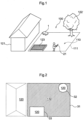
- a work area 110 in which the autonomous traveling work machine 1 is to effect a grass cutting work is to be determined.
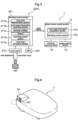
- the autonomous traveling grass mower 1 includes a grass mower control section 11, a traveling machine body 12 and a grass cutting section 13 and includes also an operation terminal 21 detachably attached thereto.
- the grass mower control section 11 includes a work area information acquisition section 11a and a traveling control section 11b.
- the autonomous traveling grass mower 1 is capable of wireless communication with the operation terminal 21, so that the above devices can be remotely controlled via the operation terminal 21.
- the operation terminal 21 constitutes the work area determination system 2 and includes a terminal control section 211, a touch panel 212 operable as a "displaying section", and a GPS 213 as a "positioning device".
- the terminal control section 211 includes a work area determination section 211a, a work area information outputting section 211b, a terminal position information recording section 211c, a recording control section 211d and a work area correction section 211e.
- the GPS 213 functions as a positioning device for acquiring terminal acquired information indicative of a position of the operation terminal 21 and functions also as a positioning device for acquiring self machine position information indicative of a self machine position of the autonomous traveling grass mower 1 when the operation terminal 21 is attached to the autonomous traveling grass mower 1.
- the touch panel 212 functions as a displaying section and functions also as an inputting means for a user.
- the field 100 includes, as "excluded areas” 120, a house 121, a tree 122, and a flower bed 123, which need to be excluded from the work area 110.
- the operation terminal 21 is employed as an example of the work area determination system 2 for setting the work area 110 in such field 100 and controlling the autonomous traveling grass mower 1.
- the recording control section 211d causes the terminal position information recording section 211c to start acquisition of the terminal position information by the GPS 213, so that the terminal position information recording section 211c will record such terminal position information sequentially. Then, the user, as holding the operation terminal 21 set to the state for the sequential recording of the terminal position information, will move with using desired moving means such as a UV, etc. or on foot along a boundary 111 on the inner/outer side of the work area 111.
- the user After encircling movement once all around the boundary 111, the user will operate the touch panel 212 to instruct end of the work area input operation to the recording control section 211d, whereby the recording control section 211d will cause the terminal positon information recording section 211c to end the inputting of the work area.
- the touch panel 212 Upon completion of the work area input, the touch panel 212 will show thereon a prerecorded map which illustrates a schematic of the field 100.
- the terminal control section 211 causes drawing of a first closed curve 31 on the map of the field 100.
- the work area determination section 211a will automatically recognize the inside of this first closed curve drawn based on the boundary 111 as the work area 110.
- the work area determination section 211a will recognize the outside of this first closed curve 31 as the excluded area 120.
- the user will walk around the outer circumferences of the tree 122 and the flower bed 123 respectively to cause the operation terminal 21 to record the terminal position information.
- closed curves drawn based on the terminal position information sequentially recorded in the course of round encircling traveling around the tree 122 and the flower bed 123 will be drawn on the map of the field 100.
- a second closed curve 32 representing the tree 122 and a third closed curve 33 representing the flower bed 123 will be drawn, upon which the work area determination section 211a will automatically incorporate the insides of the second closed curve 32 and the third closed curve 33 to the excluded area 120.
- the position, the shape and the size of the respective closed curve can be changed by operating the touch panel 212.
- This operation method can be finger tracing of the closed curve displayed on the touch panel 212, for instance.
- the work area correction section 122e will correct the contour or the position of the work area 110 obtained by the work area determination section 211a.
- the work area determination section 211a After completion of the setting of the work area 110, the work area determination section 211a automatically determines a traveling route of the autonomous traveling grass mower 1 and the work area information outputting section 211b transmits this work area and the traveling route to the work area information acquisition section 11a of the autonomous traveling grass mower 1. Thereafter, the user will instruct, by using the operation terminal 21, starting of a grass cutting work to the autonomous traveling grass mower 1 and also will attach the operation terminal 21 to the autonomous traveling grass mower 1. Then, the traveling control section 11b will cause the traveling machine body 12 to travel to guide the autonomous traveling grass mower 1 on the traveling route, based on the self machine position information acquired with use of the GPS 213. While traveling on the traveling route, the autonomous traveling grass mower 1 will effect a grass cutting work with controlling the grass cutting section 13. After completion of the grass cutting work in the entire work field 110, the autonomous traveling grass mower 1 will return to a charging device and stop operation and start power charging.
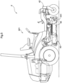
- An autonomous traveling grass mower 1' relating to the present invention includes a cut grass discharging outlet 14.
- This cut grass discharging outlet 14 is opened to the right side relative to the forward traveling direction of the autonomous traveling grass mower 1', so that cut grass clippings produced from a work can be discharged to the right side relative to the forward traveling direction of the autonomous traveling grass mower 1'.
- the cut grass discharging outlet 14 can be opened/closed with a shutter 141.
- a cut grass discharging area (not shown) can be set.
- the method of this setting of the cut grass discharging area can be made based on recording of the terminal position information by walking, similarly to the setting method of the exclusion area 120 (see Fig. 2 ) or can be made based on displaying on the touch panel 212.
- the work area determination section 211a (see Fig. 2 ) will automatically set a traveling route of the autonomous traveling grass mower 1'.
- the traveling route will be set such that cut grass clippings discharged from the cut grass discharging outlet 14 may be discharged toward the cut grass discharging area.
- the traveling route will be set such that the right lateral face of the autonomous traveling grass mower 1' will face the cut grass discharging area.
- the orientation of the cut grass discharging outlet 14 will be judged based on the self machine position information and the forward traveling direction of the autonomous traveling grass mower 1' and discharge of cut grass clippings can be controlled in such a manner that cut grass clipping will be discharged only when the cut grass discharging outlet 14 is oriented toward the cut grass discharging area.
- such grass discharging area can be the work area 110 (see Fig. 1 ).
- the cut grass discharging outlet 14 faces a position where cut grass clippings should not be discharged, e.g. the house 121 (see Fig. 1 ), the flower bed 123 (see Fig. 1 ), etc.
- the autonomous traveling grass mower 1' will be controlled so as to temporarily stop discharging of cut grass clippings by shutting the shutter 141.
- the autonomous traveling grass mower 1' is equipped with the cut grass discharging outlet 14, it is possible to carry out a discharging type grass cutting work in which a grass cutting work is carried out with discharging cut grass clippings produced thereby being discharged simultaneously. Further, the setting for effecting discharging of cut grass clippings associated with the discharging type grass cutting work toward an appropriate position can be made easily. In the discharging type work, cut grass clippings are discharged immediately. So, this discharging type work is advantageous in the respect of possibility of reduction of power loss, over the mulching type work in which cut grass clippings will be left as they are.
- the autonomous traveling grass mower 1 acquires self machine position information with using the GPS 213 (see Fig. 3 ) of the operation terminal 21 attached thereto.
- the invention is not limited to such arrangement; instead, the autonomous traveling work machine can include a positioning device which is provided separately of the operation terminal.
- the operation terminal 21 may include at least the touch panel 212, the GPS 213, the terminal position information recording section 211c and the recording control section 211d and transmit acquired terminal position information to the autonomous traveling grass mower or to any other device, so that the settings and correction of the work area 110 etc. may be effected in the autonomous traveling grass mower or to any other device.
- the autonomous traveling grass mower for which the work area is to be determined by the inventive work area determination system can be a vehicle on which a worker can ride.
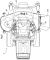
- a riding type grass mower 4 is shown in Fig. 5 and 6 .
- This riding type grass mower 4 includes a traveling machine body 42, a grass cutting section 43 and a cut grass discharging outlet 44.
- the traveling machine body 42 includes a cockpit 421 in which a worker can ride and carry out maneuvering by manual operations.
- the cockpit 421 can accommodate the work area determination system 2 (see always Fig. 3 in the following discussion) and the riding type grass mower 4 can be autonomously controlled by the work area determination system 2 as well.
- the cut grass discharging outlet 44 includes a shutter 441 capable of opening/closing this outlet by pivoting about an axis provided substantially parallel with the forward traveling direction of the traveling machine body 42. Opening/closing of the shutter 441 can be controlled by the work area determination system 2 or by a manual operation, whereby discharging of cut grass clippings and stopping of discharging can be switched over.
- the work area determination system 2 is constituted of hardware.
- at least a portion of the work area determination system 2 may be constituted of a program executable by a computer.
Landscapes
- Engineering & Computer Science (AREA)
- Radar, Positioning & Navigation (AREA)
- Remote Sensing (AREA)
- Life Sciences & Earth Sciences (AREA)
- Environmental Sciences (AREA)
- Physics & Mathematics (AREA)
- Aviation & Aerospace Engineering (AREA)
- General Physics & Mathematics (AREA)
- Automation & Control Theory (AREA)
- General Engineering & Computer Science (AREA)
- Harvester Elements (AREA)
- Guiding Agricultural Machines (AREA)
- Control Of Position, Course, Altitude, Or Attitude Of Moving Bodies (AREA)
Claims (6)
- Arbeitsbereich-Bestimmungssystem (2) für einen autonomen fahrenden Rasenmäher (1'), der basierend auf Selbstmaschinen-Positionsinformationen, die indikativ für eine Selbstmaschinen-Position des autonomen fahrenden Rasenmähers (1') sind, autonom gesteuert wird, das Arbeitsbereich-Bestimmungssystem (2) umfassend ein Bedienterminal (21) umfasst, das in der Lage ist, einen Arbeitsbereich (110) zu bestimmen;
wobei- das Bedienterminal (21) eine Terminalpositionierungsvorrichtung (213) zum Erfassen von Terminalpositionsinformationen, die indikativ für eine Position des Bedienterminals (21) sind, einen Arbeitsbereich-Bestimmungsabschnitt (211a), der konfiguriert ist, um den Arbeitsbereich (110) basierend auf den Terminalpositionsinformationen zu bestimmen, und einen Arbeitsbereich-Informationsausgabeabschnitt (211b) zum Ausgeben von Arbeitsbereich-Informationen, die Informationen sind, die sich auf den bestimmten Arbeitsbereich (110) beziehen, beinhaltet,- das Bedienterminal (21) abnehmbar an dem autonomen fahrenden Rasenmäher (1') angebracht ist,- das Bedienterminal (21) konfiguriert ist, um den Arbeitsbereich (110) in Assoziierung mit einer Bewegung eines Benutzers einstellt, der das Bedienterminal (21) in einem Zustand hält, in dem ein Aufzeichnen der Terminalpositionsinformationen durch die Terminalpositionierungsvorrichtung (213) an einem äußeren Rand eines Bereichs ausgeführt werden soll, in dem eine Arbeit im Feld durchgeführt werden soll;das Arbeitsbereich-Bestimmungssystem (2) dadurch gekennzeichnet ist, dass der autonome fahrende Rasenmäher einen Schnittgras-Ausgabeauslass (14) beinhaltet, wobei der Schnittgras-Ausgabeauslass (14) mit einem Verschluss (141) zur rechten Seite in Bezug auf eine Vorwärtsfahrtrichtung des autonomen fahrenden Rasenmähers (1') geschlossen und geöffnet wird, sodass von einer Arbeit erzeugte Schnittgrasreste zu der rechten Seite in Bezug auf die Vorwärtsfahrtrichtung des autonomen fahrenden Rasenmähers (1') ausgegeben werden können;
wobei- die Ausrichtung des Schnittgras-Ausgabeauslasses (14) basierend auf den Selbstmaschinen-Positionsinformationen und die Vorwärtsfahrtrichtung des autonomen fahrenden Rasenmähers (1') beurteilt wird; und- eine Ausgabe von Schnittgrasesten auf eine Weise gesteuert wird, dass Schnittgrasreste nur dann ausgegeben werden, wenn der Schnittgras-Ausgabeauslass (14) auf einen Schnittgras-Ausgabebereich ausgerichtet ist; wobei die Ausgabe vorübergehend durch Schließen des Verschlusses angehalten wird, wenn der Schnittgras-Ausgabeauslass (14) auf eine Position ausgerichtet ist, in der keine Schnittgrasreste ausgegeben werden sollen. - Arbeitsbereich-Bestimmungssystem (2) nach Anspruch 1, wobei:
das Bedienterminal (21) ferner einen Terminalposition-Informationsaufzeichnungsabschnitt (211c) zum Aufzeichnen der Terminalpositionsinformationen und einen Aufzeichnungssteuerungsabschnitt (211d) zum Steuern einer Ausführung und eines Anhaltens einer Aufzeichnung der Terminalpositionsinformationen beinhaltet; und der Arbeitsbereich-Bestimmungsabschnitt (211a) konfiguriert ist, um den Arbeitsbereich (110) basierend auf dem Verlauf der Terminalpositionsinformationen, die in dem Terminalposition-Informationsaufzeichnungsabschnitt (211c) aufgezeichnet sind, zu bestimmen. - Arbeitsbereich-Bestimmungssystem (2) nach Anspruch 1 oder 2, wobei:das Bedienterminal (21) ferner einen Anzeigeabschnitt (212) zum Anzeigen einer Karte eines Bereichs einschließlich des Arbeitsbereichs (110) beinhaltet, wobei der Arbeitsbereich (110), der durch den Arbeitsbereich-Bestimmungsabschnitt (211a) bestimmt wird, auf eine Weise angezeigt wird, die der Karte in dem Anzeigeabschnitt (212) überlagert ist; undein Arbeitsbereich-Korrekturabschnitt (211e) zum Korrigieren des Arbeitsbereichs (110) basierend auf einer Benutzeroperation auf dem in dem Anzeigeabschnitt (212) angezeigten Arbeitsbereich bereitgestellt ist.
- Arbeitsbereich-Bestimmungssystem nach einem der Ansprüche 1 bis 3, wobei, wenn das Bedienterminal (21) angebracht ist, das Bedienterminal (21) die Terminalpositionsinformationen als die Arbeitsmaschinenpositionsinformationen an den autonomen fahrenden Rasenmäher (1) überträgt.
- Autonomer fahrender Rasenmäher (1') umfassend:einen fahrenden Maschinenkörper (42);eine Arbeitsmaschinen-Positionierungsvorrichtung zum Erfassen von Selbstmaschinenpositionsinformationen, die indikativ für die Selbstmaschinenposition sind;einen Arbeitsbereich-Informationserfassungsabschnitt (11a) zum Erfassen von Arbeitsbereichsinformationen, die indikativ für einen Arbeitsbereich (110) sind; undeinen Fahrsteuerungsabschnitt (11b) zum Steuern eines Fahrens des autonomen fahrenden Rasenmäherkörpers basierend auf den Selbstmaschinenpositionsinformationen und den Arbeitsbereich-Informationen, sodass der autonome fahrende Rasenmäherkörper (12; 42) innerhalb des Arbeitsbereichs (110) fahren kann;wobei der Arbeitsbereich-Informationserfassungsabschnitt (11a) konfiguriert ist, um die Arbeitsbereich-Informationen von einem Bedienterminal (21) eines Arbeitsbereich-Bestimmungssystems (2) nach einem der Ansprüche 1 bis 4 zu erfassen;der autonome fahrende Rasenmäher dadurch gekennzeichnet ist, dass er einen Schnittgras-Ausgabeauslass (14) aufweist, der mit einem Verschluss (141) zu der rechten Seite in Bezug auf eine Vorwärtsfahrtrichtung des autonomen fahrenden Rasenmähers (1') geschlossen und geöffnet wird, sodass von einer Arbeit erzeugte Schnittgrasreste zu der rechten Seite in Bezug auf eine Vorwärtsfahrtrichtung des autonomen fahrenden Rasenmähers (1') ausgegeben werden können;wobei- die Ausrichtung des Schnittgras-Ausgabeauslasses (14) basierend auf den Selbstmaschinen-Positionsinformationen und die Vorwärtsfahrtrichtung des autonomen fahrenden Rasenmähers (1') beurteilt wird; und- eine Ausgabe von Schnittgrasesten auf eine Weise gesteuert wird, dass Schnittgrasreste nur dann ausgegeben werden, wenn der Schnittgras-Ausgabeauslass (14) auf einen Schnittgras-Ausgabebereich ausgerichtet ist;wobei die Ausgabe vorübergehend durch Schließen des Verschlusses angehalten wird, wenn der Schnittgras-Ausgabeauslass (14) auf eine Position ausgerichtet ist, in der keine Schnittgrasreste ausgegeben werden sollen.
- Arbeitsbereich-Bestimmungsverfahren für einen autonomen fahrenden Rasenmäher (1'), der basierend auf einer Selbstmaschinenposition, die indikativ für eine Position des autonomen fahrenden Rasenmähers (1') ist, autonom gesteuert wird, das Arbeitsbereich-Bestimmungsverfahren umfassend folgende computerausführbare Funktionen:eine Positionierungsfunktion zum Erfassen von Terminalpositionsinformationen, die indikativ für eine Position eines Bedienterminals (21) sind, das abnehmbar an dem autonomen fahrenden Rasenmäher (1') anbringbar ist und das dieses Arbeitsbereich-Bestimmungsprogramm darin speichert;eine Arbeitsbereich-Bestimmungsfunktion zum Bestimmen eines Arbeitsbereichs (110) basierend auf den Terminalpositionsinformationen;eine Arbeitsbereich-Informationsausgabefunktion zum Ausgeben von Arbeitsbereichsinformationen, die Informationen über den bestimmten Arbeitsbereich (110) sind, wobei der Arbeitsbereich in Assoziation mit einer Bewegung eines Benutzers festgelegt wird, der das Bedienterminal hält, das in einem Zustand festgelegt wird, in dem die Aufzeichnung der Terminalpositionsinformationen an einem äußeren Rand eines Bereichs ausgeführt werden soll, in dem eine Arbeit im Feld durchgeführt werden soll; undeine Steuerungsfunktion zum Steuern des Öffnens und des Schließens eines Verschlusses eines Schnittgras-Ausgabeauslasses (14), der an dem autonomen fahrenden Rasenmäher bereitgestellt ist;wobei- der Schnittgras-Ausgabeauslass (14) mit dem Verschluss zu der rechten Seite in Bezug auf eine Vorwärtsfahrtrichtung des autonomen fahrenden Rasenmähers (1') geschlossen und geöffnet wird, sodass von einer Arbeit erzeugte Schnittgrasreste zu der rechten Seite in Bezug auf die Vorwärtsfahrtrichtung des autonomen fahrenden Rasenmähers (1') ausgegeben werden können;- die Ausrichtung des Schnittgras-Ausgabeauslasses (14) basierend auf den Selbstmaschinen-Positionsinformationen und die Vorwärtsfahrtrichtung des autonomen fahrenden Rasenmähers (1') beurteilt wird; undeine Ausgabe von Schnittgrasesten auf eine Weise gesteuert wird, dass Schnittgrasreste nur dann ausgegeben werden, wenn der Schnittgras-Ausgabeauslass (14) auf einen Schnittgras-Ausgabebereich ausgerichtet ist;wobei die Ausgabe vorübergehend durch Schließen des Verschlusses angehalten wird, wenn der Schnittgras-Ausgabeauslass (14) auf eine Position ausgerichtet ist, in der keine Schnittgrasreste ausgegeben werden sollen.
Applications Claiming Priority (1)
| Application Number | Priority Date | Filing Date | Title |
|---|---|---|---|
| JP2017252061A JP6877330B2 (ja) | 2017-12-27 | 2017-12-27 | 自律走行型作業機のための作業領域決定システム、自律走行型作業機、および、作業領域決定プログラム |
Publications (3)
| Publication Number | Publication Date |
|---|---|
| EP3506039A1 EP3506039A1 (de) | 2019-07-03 |
| EP3506039B1 EP3506039B1 (de) | 2022-05-25 |
| EP3506039B2 true EP3506039B2 (de) | 2025-03-12 |
Family
ID=64362348
Family Applications (1)
| Application Number | Title | Priority Date | Filing Date |
|---|---|---|---|
| EP18206747.0A Active EP3506039B2 (de) | 2017-12-27 | 2018-11-16 | Arbeitsbereichsbestimmungssystem für eine autonom fahrendes arbeitsmaschine, autonom fahrende arbeitsmaschine und arbeitsbereichsbestimmungsprogramm |
Country Status (3)
| Country | Link |
|---|---|
| US (1) | US11119495B2 (de) |
| EP (1) | EP3506039B2 (de) |
| JP (1) | JP6877330B2 (de) |
Families Citing this family (11)
| Publication number | Priority date | Publication date | Assignee | Title |
|---|---|---|---|---|
| US11234365B2 (en) * | 2017-10-31 | 2022-02-01 | Clark Equipment Company | Baffles for mower deck |
| US11182694B2 (en) * | 2018-02-02 | 2021-11-23 | Samsung Electronics Co., Ltd. | Data path for GPU machine learning training with key value SSD |
| US10872302B2 (en) * | 2018-12-13 | 2020-12-22 | Caterpillar Inc. | Automatically determining construction worksite operational zones based on received construction equipment telemetry data |
| JP7288417B2 (ja) * | 2020-03-31 | 2023-06-07 | 本田技研工業株式会社 | 自律作業システム、自律作業設定方法、およびプログラム |
| EP4142464B1 (de) * | 2020-04-27 | 2024-11-13 | iRobot Corporation | Verfahren zur überwachung von autonomen roboterrasenmähern |
| DE102020211960A1 (de) * | 2020-09-24 | 2022-03-24 | Ford Global Technologies, Llc | Kartierung eines befahrbaren Bereiches |
| CN114375676B (zh) * | 2020-10-16 | 2023-04-21 | 南京泉峰科技有限公司 | 自移动设备及其控制方法和自移动工作系统 |
| US20230090730A1 (en) * | 2021-09-17 | 2023-03-23 | Scythe Robotics, Inc. | Mower components |
| TWI808048B (zh) * | 2023-01-19 | 2023-07-01 | 優式機器人股份有限公司 | 邊界定位裝置 |
| JP2025145951A (ja) * | 2024-03-22 | 2025-10-03 | 井関農機株式会社 | 作業車両 |
| CN118633417A (zh) * | 2024-06-25 | 2024-09-13 | 深圳库犸科技有限公司 | 基于集草功能的控制方法及相关装置 |
Citations (23)
| Publication number | Priority date | Publication date | Assignee | Title |
|---|---|---|---|---|
| US20030144774A1 (en) † | 2002-01-29 | 2003-07-31 | Trissel Ronald L. | Kit and method for converting conventional lawnmower to a robotic lawnmower |
| GB2517572A (en) † | 2013-06-28 | 2015-02-25 | Bosch Gmbh Robert | Method for a working region acquisition of at least one working region of an autonomous service robot |
| EP2946650A1 (de) † | 2014-05-19 | 2015-11-25 | Outils Wolf (Société par Actions Simplifiée) | Verfahren zur verwendung eines roboters zur bodenbehandlung, und entsprechendes system |
| US20160026185A1 (en) † | 2013-03-15 | 2016-01-28 | Mtd Products Inc | Autonomous mobile work system comprising a variable reflectivity base station |
| US20160091898A1 (en) † | 2014-09-26 | 2016-03-31 | Steven R. Booher | Intelligent Control Apparatus, System, and Method of Use |
| US20160165795A1 (en) † | 2014-12-15 | 2016-06-16 | Irobot Corporation | Robot lawnmower mapping |
| US20170168501A1 (en) † | 2014-02-06 | 2017-06-15 | Yanmar Co., Ltd. | Method for Setting Travel Path of Autonomous Travel Work Vehicle |
| WO2017154715A1 (ja) † | 2016-03-09 | 2017-09-14 | ヤンマー株式会社 | 作業車両および走行領域特定装置 |
| JP2017167838A (ja) † | 2016-03-16 | 2017-09-21 | ヤンマー株式会社 | 経路生成装置 |
| WO2017167207A1 (zh) † | 2016-03-29 | 2017-10-05 | 苏州宝时得电动工具有限公司 | 自动工作系统及其工作区域的地图建立方法 |
| WO2017177978A1 (zh) † | 2016-04-15 | 2017-10-19 | 苏州宝时得电动工具有限公司 | 自动工作系统、移动设备及其控制方法 |
| WO2018055922A1 (ja) † | 2016-09-26 | 2018-03-29 | ヤンマー株式会社 | 経路生成システム |
| WO2018086612A1 (zh) † | 2016-11-11 | 2018-05-17 | 苏州宝时得电动工具有限公司 | 自动工作系统及其控制方法 |
| WO2018108179A1 (zh) † | 2016-12-15 | 2018-06-21 | 苏州宝时得电动工具有限公司 | 自移动设备及其定位故障报警方法和自动工作系统 |
| WO2018108178A1 (zh) † | 2016-12-15 | 2018-06-21 | 苏州宝时得电动工具有限公司 | 自移动设备的回归方法、自移动设备、存储介质和服务器 |
| WO2018139024A1 (ja) † | 2017-01-27 | 2018-08-02 | ヤンマー株式会社 | 経路生成システム、及びそれによって生成された経路に沿って作業車両を走行させる自律走行システム |
| WO2018153599A1 (de) † | 2017-02-24 | 2018-08-30 | Robert Bosch Gmbh | Verfahren zu einer erfassung zumindest eines arbeitsbereichs eines autonomen arbeitsgeräts |
| WO2018224678A1 (de) † | 2017-06-09 | 2018-12-13 | Andreas Stihl Ag & Co. Kg | Grünflächenbearbeitungssystem, verfahren zum erfassen mindestens eines abschnitts eines begrenzungsrands einer zu bearbeitenden fläche und verfahren zum betreiben eines autonomen mobilen grünflächenbearbeitungsroboters |
| EP3491906A1 (de) † | 2017-11-30 | 2019-06-05 | LG Electronics Inc. | Mobiler roboter und verfahren zur steuerung davon |
| EP3495910A1 (de) † | 2017-11-30 | 2019-06-12 | LG Electronics Inc. | Mobiler roboter und verfahren zur steuerung davon |
| WO2019185930A1 (en) † | 2018-03-30 | 2019-10-03 | Positec Power Tools (Suzhou) Co., Ltd | Self-moving device, working system, automatic scheduling method and method for calculating area |
| EP3603370A1 (de) † | 2018-08-03 | 2020-02-05 | Lg Electronics Inc. | Beweglicher roboter, verfahren zur steuerung eines beweglichen roboters und bewegliches robotersystem |
| WO2020030066A1 (zh) † | 2018-08-08 | 2020-02-13 | 苏州宝时得电动工具有限公司 | 自移动设备、自动工作系统及其控制方法 |
Family Cites Families (19)
| Publication number | Priority date | Publication date | Assignee | Title |
|---|---|---|---|---|
| JPS59179527U (ja) * | 1983-05-20 | 1984-11-30 | 株式会社クボタ | モ−アの刈草案内装置 |
| US6101794A (en) * | 1998-06-03 | 2000-08-15 | Terracare Products Company, Inc. | Mower |
| JP5626773B2 (ja) * | 2010-06-22 | 2014-11-19 | ヤンマー株式会社 | 電動草刈機 |
| JP2013122675A (ja) * | 2011-12-09 | 2013-06-20 | Yanmar Co Ltd | 電動作業車両 |
| JP5836151B2 (ja) | 2012-02-10 | 2015-12-24 | 本田技研工業株式会社 | 無人走行作業車用エリアワイヤの配置構造およびその制御装置 |
| EP2639128B1 (de) * | 2012-03-13 | 2023-09-06 | Kanzaki Kokyukoki Mfg. Co., Ltd. | Nutzfahrzeug |
| KR101410981B1 (ko) * | 2012-11-26 | 2014-06-23 | 조선대학교산학협력단 | 자율 작업형 잔디깎기 장치 |
| JP6240384B2 (ja) | 2012-11-29 | 2017-11-29 | ヤンマー株式会社 | 自律走行作業システム |
| JP6021717B2 (ja) * | 2013-03-29 | 2016-11-09 | 株式会社クボタ | 作業管理支援装置及び作業管理システム |
| JP2016010382A (ja) | 2014-06-30 | 2016-01-21 | 日立工機株式会社 | 自走式草刈機 |
| JP6253567B2 (ja) * | 2014-11-17 | 2017-12-27 | ヤンマー株式会社 | 作業車両の移動システム |
| US9750186B2 (en) * | 2015-01-13 | 2017-09-05 | The Toro Company | Walk-behind mower including debris container |
| US10034421B2 (en) | 2015-07-24 | 2018-07-31 | Irobot Corporation | Controlling robotic lawnmowers |
| JP2017091246A (ja) * | 2015-11-11 | 2017-05-25 | 有限会社曽田農機設計事務所 | 刈取ロボット及びそれを用いた自動刈取システム |
| WO2017159801A1 (ja) | 2016-03-18 | 2017-09-21 | ヤンマー株式会社 | 自律走行システム |
| JP6571567B2 (ja) * | 2016-03-18 | 2019-09-04 | ヤンマー株式会社 | 作業車両用経路生成システム |
| JP6727645B2 (ja) * | 2016-05-24 | 2020-07-22 | 小橋工業株式会社 | 作業機操作プログラム |
| JP6694328B2 (ja) | 2016-05-27 | 2020-05-13 | ヤンマー株式会社 | 自律走行システム |
| JP2019004793A (ja) * | 2017-06-26 | 2019-01-17 | 株式会社クボタ | 作業車 |
-
2017
- 2017-12-27 JP JP2017252061A patent/JP6877330B2/ja active Active
-
2018
- 2018-11-13 US US16/188,371 patent/US11119495B2/en active Active
- 2018-11-16 EP EP18206747.0A patent/EP3506039B2/de active Active
Patent Citations (26)
| Publication number | Priority date | Publication date | Assignee | Title |
|---|---|---|---|---|
| US20030144774A1 (en) † | 2002-01-29 | 2003-07-31 | Trissel Ronald L. | Kit and method for converting conventional lawnmower to a robotic lawnmower |
| US20160026185A1 (en) † | 2013-03-15 | 2016-01-28 | Mtd Products Inc | Autonomous mobile work system comprising a variable reflectivity base station |
| GB2517572A (en) † | 2013-06-28 | 2015-02-25 | Bosch Gmbh Robert | Method for a working region acquisition of at least one working region of an autonomous service robot |
| US20170168501A1 (en) † | 2014-02-06 | 2017-06-15 | Yanmar Co., Ltd. | Method for Setting Travel Path of Autonomous Travel Work Vehicle |
| EP2946650A1 (de) † | 2014-05-19 | 2015-11-25 | Outils Wolf (Société par Actions Simplifiée) | Verfahren zur verwendung eines roboters zur bodenbehandlung, und entsprechendes system |
| US20160091898A1 (en) † | 2014-09-26 | 2016-03-31 | Steven R. Booher | Intelligent Control Apparatus, System, and Method of Use |
| US20160165795A1 (en) † | 2014-12-15 | 2016-06-16 | Irobot Corporation | Robot lawnmower mapping |
| EP3427562A1 (de) † | 2016-03-09 | 2019-01-16 | Yanmar Co., Ltd. | Nutzfahrzeug und reiseregionspezifizierungsvorrichtung |
| WO2017154715A1 (ja) † | 2016-03-09 | 2017-09-14 | ヤンマー株式会社 | 作業車両および走行領域特定装置 |
| JP2017167838A (ja) † | 2016-03-16 | 2017-09-21 | ヤンマー株式会社 | 経路生成装置 |
| WO2017167207A1 (zh) † | 2016-03-29 | 2017-10-05 | 苏州宝时得电动工具有限公司 | 自动工作系统及其工作区域的地图建立方法 |
| EP3444694A1 (de) † | 2016-04-15 | 2019-02-20 | Positec Power Tools (Suzhou) Co., Ltd | Automatisches arbeitssystem, mobile vorrichtung und steuerungsverfahren dafür |
| WO2017177978A1 (zh) † | 2016-04-15 | 2017-10-19 | 苏州宝时得电动工具有限公司 | 自动工作系统、移动设备及其控制方法 |
| WO2018055922A1 (ja) † | 2016-09-26 | 2018-03-29 | ヤンマー株式会社 | 経路生成システム |
| WO2018086612A1 (zh) † | 2016-11-11 | 2018-05-17 | 苏州宝时得电动工具有限公司 | 自动工作系统及其控制方法 |
| WO2018108179A1 (zh) † | 2016-12-15 | 2018-06-21 | 苏州宝时得电动工具有限公司 | 自移动设备及其定位故障报警方法和自动工作系统 |
| WO2018108178A1 (zh) † | 2016-12-15 | 2018-06-21 | 苏州宝时得电动工具有限公司 | 自移动设备的回归方法、自移动设备、存储介质和服务器 |
| EP3557359A1 (de) † | 2016-12-15 | 2019-10-23 | Positec Power Tools (Suzhou) Co., Ltd | Wendeverfahren für selbstbewegende vorrichtung, selbstbewegende vorrichtung, speichermedium und server |
| WO2018139024A1 (ja) † | 2017-01-27 | 2018-08-02 | ヤンマー株式会社 | 経路生成システム、及びそれによって生成された経路に沿って作業車両を走行させる自律走行システム |
| WO2018153599A1 (de) † | 2017-02-24 | 2018-08-30 | Robert Bosch Gmbh | Verfahren zu einer erfassung zumindest eines arbeitsbereichs eines autonomen arbeitsgeräts |
| WO2018224678A1 (de) † | 2017-06-09 | 2018-12-13 | Andreas Stihl Ag & Co. Kg | Grünflächenbearbeitungssystem, verfahren zum erfassen mindestens eines abschnitts eines begrenzungsrands einer zu bearbeitenden fläche und verfahren zum betreiben eines autonomen mobilen grünflächenbearbeitungsroboters |
| EP3491906A1 (de) † | 2017-11-30 | 2019-06-05 | LG Electronics Inc. | Mobiler roboter und verfahren zur steuerung davon |
| EP3495910A1 (de) † | 2017-11-30 | 2019-06-12 | LG Electronics Inc. | Mobiler roboter und verfahren zur steuerung davon |
| WO2019185930A1 (en) † | 2018-03-30 | 2019-10-03 | Positec Power Tools (Suzhou) Co., Ltd | Self-moving device, working system, automatic scheduling method and method for calculating area |
| EP3603370A1 (de) † | 2018-08-03 | 2020-02-05 | Lg Electronics Inc. | Beweglicher roboter, verfahren zur steuerung eines beweglichen roboters und bewegliches robotersystem |
| WO2020030066A1 (zh) † | 2018-08-08 | 2020-02-13 | 苏州宝时得电动工具有限公司 | 自移动设备、自动工作系统及其控制方法 |
Also Published As
| Publication number | Publication date |
|---|---|
| JP6877330B2 (ja) | 2021-05-26 |
| US20190196483A1 (en) | 2019-06-27 |
| US11119495B2 (en) | 2021-09-14 |
| EP3506039A1 (de) | 2019-07-03 |
| EP3506039B1 (de) | 2022-05-25 |
| JP2019115313A (ja) | 2019-07-18 |
Similar Documents
| Publication | Publication Date | Title |
|---|---|---|
| EP3506039B2 (de) | Arbeitsbereichsbestimmungssystem für eine autonom fahrendes arbeitsmaschine, autonom fahrende arbeitsmaschine und arbeitsbereichsbestimmungsprogramm | |
| CN107613751B (zh) | 作业车辆支援系统 | |
| US10197407B2 (en) | Method and robot system for autonomous control of a vehicle | |
| EP3613270B1 (de) | Intelligenter mäher auf basis von lidar-kartenerstellung | |
| JP6749448B2 (ja) | 作業車支援システム | |
| EP4068943B1 (de) | Roboter-arbeitswerkzeug, system und verfahren zu dessen betrieb | |
| JP6929190B2 (ja) | 自律走行型作業機のための作業領域決定システム | |
| EP3330824A1 (de) | Verfahren und robotersystem für unabhängige fahrzeugsteuerung | |
| KR102869496B1 (ko) | 자동 주행 제어 시스템, 자동 주행 제어 프로그램, 자동 주행 제어 프로그램을 기록한 기록 매체, 자동 주행 제어 방법, 제어 장치, 제어 프로그램, 제어 프로그램을 기록한 기록 매체, 제어 방법 | |
| KR101202399B1 (ko) | 농업용 잔디 예초 모우어 로봇 및 그의 주행 안내방법 | |
| US11582903B1 (en) | Vision based guidance system and method for lawn mowing devices | |
| JP7009983B2 (ja) | 農作業支援システム | |
| CN106873581A (zh) | 自主工作器具 | |
| EP4075229B1 (de) | Verbesserte installation für ein robotisches arbeitswerkzeug | |
| US11632901B2 (en) | Autonomous travel work machine | |
| JP2023079152A (ja) | 経路生成方法、経路生成システム、及び経路生成プログラム | |
| JP7403397B2 (ja) | 農作業機 | |
| EP4472396A1 (de) | Verbesserter betrieb für ein robotisches arbeitswerkzeugsystem | |
| JP2021193514A (ja) | 作業車両の制御システム | |
| JPH05284806A (ja) | 無人芝刈機の走行制御方法 | |
| JP2022095324A (ja) | 作業車両 | |
| JP2022010873A (ja) | 作業車両の制御システム | |
| EP4473821A1 (de) | Verbesserte navigation für ein robotisches rasenmähersystem | |
| JP2022010872A (ja) | 作業車両の制御システム | |
| US12481285B2 (en) | Definition of boundary for a robotic work tool |
Legal Events
| Date | Code | Title | Description |
|---|---|---|---|
| PUAI | Public reference made under article 153(3) epc to a published international application that has entered the european phase |
Free format text: ORIGINAL CODE: 0009012 |
|
| STAA | Information on the status of an ep patent application or granted ep patent |
Free format text: STATUS: REQUEST FOR EXAMINATION WAS MADE |
|
| 17P | Request for examination filed |
Effective date: 20181116 |
|
| AK | Designated contracting states |
Kind code of ref document: A1 Designated state(s): AL AT BE BG CH CY CZ DE DK EE ES FI FR GB GR HR HU IE IS IT LI LT LU LV MC MK MT NL NO PL PT RO RS SE SI SK SM TR |
|
| AX | Request for extension of the european patent |
Extension state: BA ME |
|
| STAA | Information on the status of an ep patent application or granted ep patent |
Free format text: STATUS: EXAMINATION IS IN PROGRESS |
|
| 17Q | First examination report despatched |
Effective date: 20210208 |
|
| GRAP | Despatch of communication of intention to grant a patent |
Free format text: ORIGINAL CODE: EPIDOSNIGR1 |
|
| STAA | Information on the status of an ep patent application or granted ep patent |
Free format text: STATUS: GRANT OF PATENT IS INTENDED |
|
| INTG | Intention to grant announced |
Effective date: 20211221 |
|
| GRAS | Grant fee paid |
Free format text: ORIGINAL CODE: EPIDOSNIGR3 |
|
| GRAA | (expected) grant |
Free format text: ORIGINAL CODE: 0009210 |
|
| STAA | Information on the status of an ep patent application or granted ep patent |
Free format text: STATUS: THE PATENT HAS BEEN GRANTED |
|
| AK | Designated contracting states |
Kind code of ref document: B1 Designated state(s): AL AT BE BG CH CY CZ DE DK EE ES FI FR GB GR HR HU IE IS IT LI LT LU LV MC MK MT NL NO PL PT RO RS SE SI SK SM TR |
|
| REG | Reference to a national code |
Ref country code: GB Ref legal event code: FG4D |
|
| REG | Reference to a national code |
Ref country code: CH Ref legal event code: EP |
|
| REG | Reference to a national code |
Ref country code: AT Ref legal event code: REF Ref document number: 1494508 Country of ref document: AT Kind code of ref document: T Effective date: 20220615 Ref country code: DE Ref legal event code: R096 Ref document number: 602018035938 Country of ref document: DE |
|
| REG | Reference to a national code |
Ref country code: IE Ref legal event code: FG4D |
|
| REG | Reference to a national code |
Ref country code: LT Ref legal event code: MG9D |
|
| REG | Reference to a national code |
Ref country code: NL Ref legal event code: MP Effective date: 20220525 |
|
| REG | Reference to a national code |
Ref country code: AT Ref legal event code: MK05 Ref document number: 1494508 Country of ref document: AT Kind code of ref document: T Effective date: 20220525 |
|
| PG25 | Lapsed in a contracting state [announced via postgrant information from national office to epo] |
Ref country code: SE Free format text: LAPSE BECAUSE OF FAILURE TO SUBMIT A TRANSLATION OF THE DESCRIPTION OR TO PAY THE FEE WITHIN THE PRESCRIBED TIME-LIMIT Effective date: 20220525 Ref country code: PT Free format text: LAPSE BECAUSE OF FAILURE TO SUBMIT A TRANSLATION OF THE DESCRIPTION OR TO PAY THE FEE WITHIN THE PRESCRIBED TIME-LIMIT Effective date: 20220926 Ref country code: NO Free format text: LAPSE BECAUSE OF FAILURE TO SUBMIT A TRANSLATION OF THE DESCRIPTION OR TO PAY THE FEE WITHIN THE PRESCRIBED TIME-LIMIT Effective date: 20220825 Ref country code: NL Free format text: LAPSE BECAUSE OF FAILURE TO SUBMIT A TRANSLATION OF THE DESCRIPTION OR TO PAY THE FEE WITHIN THE PRESCRIBED TIME-LIMIT Effective date: 20220525 Ref country code: LT Free format text: LAPSE BECAUSE OF FAILURE TO SUBMIT A TRANSLATION OF THE DESCRIPTION OR TO PAY THE FEE WITHIN THE PRESCRIBED TIME-LIMIT Effective date: 20220525 Ref country code: HR Free format text: LAPSE BECAUSE OF FAILURE TO SUBMIT A TRANSLATION OF THE DESCRIPTION OR TO PAY THE FEE WITHIN THE PRESCRIBED TIME-LIMIT Effective date: 20220525 Ref country code: GR Free format text: LAPSE BECAUSE OF FAILURE TO SUBMIT A TRANSLATION OF THE DESCRIPTION OR TO PAY THE FEE WITHIN THE PRESCRIBED TIME-LIMIT Effective date: 20220826 Ref country code: FI Free format text: LAPSE BECAUSE OF FAILURE TO SUBMIT A TRANSLATION OF THE DESCRIPTION OR TO PAY THE FEE WITHIN THE PRESCRIBED TIME-LIMIT Effective date: 20220525 Ref country code: ES Free format text: LAPSE BECAUSE OF FAILURE TO SUBMIT A TRANSLATION OF THE DESCRIPTION OR TO PAY THE FEE WITHIN THE PRESCRIBED TIME-LIMIT Effective date: 20220525 Ref country code: BG Free format text: LAPSE BECAUSE OF FAILURE TO SUBMIT A TRANSLATION OF THE DESCRIPTION OR TO PAY THE FEE WITHIN THE PRESCRIBED TIME-LIMIT Effective date: 20220825 Ref country code: AT Free format text: LAPSE BECAUSE OF FAILURE TO SUBMIT A TRANSLATION OF THE DESCRIPTION OR TO PAY THE FEE WITHIN THE PRESCRIBED TIME-LIMIT Effective date: 20220525 |
|
| PG25 | Lapsed in a contracting state [announced via postgrant information from national office to epo] |
Ref country code: RS Free format text: LAPSE BECAUSE OF FAILURE TO SUBMIT A TRANSLATION OF THE DESCRIPTION OR TO PAY THE FEE WITHIN THE PRESCRIBED TIME-LIMIT Effective date: 20220525 Ref country code: PL Free format text: LAPSE BECAUSE OF FAILURE TO SUBMIT A TRANSLATION OF THE DESCRIPTION OR TO PAY THE FEE WITHIN THE PRESCRIBED TIME-LIMIT Effective date: 20220525 Ref country code: LV Free format text: LAPSE BECAUSE OF FAILURE TO SUBMIT A TRANSLATION OF THE DESCRIPTION OR TO PAY THE FEE WITHIN THE PRESCRIBED TIME-LIMIT Effective date: 20220525 Ref country code: IS Free format text: LAPSE BECAUSE OF FAILURE TO SUBMIT A TRANSLATION OF THE DESCRIPTION OR TO PAY THE FEE WITHIN THE PRESCRIBED TIME-LIMIT Effective date: 20220925 |
|
| PG25 | Lapsed in a contracting state [announced via postgrant information from national office to epo] |
Ref country code: SM Free format text: LAPSE BECAUSE OF FAILURE TO SUBMIT A TRANSLATION OF THE DESCRIPTION OR TO PAY THE FEE WITHIN THE PRESCRIBED TIME-LIMIT Effective date: 20220525 Ref country code: SK Free format text: LAPSE BECAUSE OF FAILURE TO SUBMIT A TRANSLATION OF THE DESCRIPTION OR TO PAY THE FEE WITHIN THE PRESCRIBED TIME-LIMIT Effective date: 20220525 Ref country code: RO Free format text: LAPSE BECAUSE OF FAILURE TO SUBMIT A TRANSLATION OF THE DESCRIPTION OR TO PAY THE FEE WITHIN THE PRESCRIBED TIME-LIMIT Effective date: 20220525 Ref country code: EE Free format text: LAPSE BECAUSE OF FAILURE TO SUBMIT A TRANSLATION OF THE DESCRIPTION OR TO PAY THE FEE WITHIN THE PRESCRIBED TIME-LIMIT Effective date: 20220525 Ref country code: DK Free format text: LAPSE BECAUSE OF FAILURE TO SUBMIT A TRANSLATION OF THE DESCRIPTION OR TO PAY THE FEE WITHIN THE PRESCRIBED TIME-LIMIT Effective date: 20220525 Ref country code: CZ Free format text: LAPSE BECAUSE OF FAILURE TO SUBMIT A TRANSLATION OF THE DESCRIPTION OR TO PAY THE FEE WITHIN THE PRESCRIBED TIME-LIMIT Effective date: 20220525 |
|
| REG | Reference to a national code |
Ref country code: DE Ref legal event code: R026 Ref document number: 602018035938 Country of ref document: DE |
|
| PLBI | Opposition filed |
Free format text: ORIGINAL CODE: 0009260 |
|
| PG25 | Lapsed in a contracting state [announced via postgrant information from national office to epo] |
Ref country code: AL Free format text: LAPSE BECAUSE OF FAILURE TO SUBMIT A TRANSLATION OF THE DESCRIPTION OR TO PAY THE FEE WITHIN THE PRESCRIBED TIME-LIMIT Effective date: 20220525 |
|
| 26 | Opposition filed |
Opponent name: KILBURN & STRODE LLP Effective date: 20230223 |
|
| PLAX | Notice of opposition and request to file observation + time limit sent |
Free format text: ORIGINAL CODE: EPIDOSNOBS2 |
|
| PG25 | Lapsed in a contracting state [announced via postgrant information from national office to epo] |
Ref country code: SI Free format text: LAPSE BECAUSE OF FAILURE TO SUBMIT A TRANSLATION OF THE DESCRIPTION OR TO PAY THE FEE WITHIN THE PRESCRIBED TIME-LIMIT Effective date: 20220525 |
|
| REG | Reference to a national code |
Ref country code: DE Ref legal event code: R119 Ref document number: 602018035938 Country of ref document: DE |
|
| PG25 | Lapsed in a contracting state [announced via postgrant information from national office to epo] |
Ref country code: MC Free format text: LAPSE BECAUSE OF FAILURE TO SUBMIT A TRANSLATION OF THE DESCRIPTION OR TO PAY THE FEE WITHIN THE PRESCRIBED TIME-LIMIT Effective date: 20220525 |
|
| REG | Reference to a national code |
Ref country code: CH Ref legal event code: PL |
|
| GBPC | Gb: european patent ceased through non-payment of renewal fee |
Effective date: 20221116 |
|
| REG | Reference to a national code |
Ref country code: BE Ref legal event code: MM Effective date: 20221130 |
|
| PG25 | Lapsed in a contracting state [announced via postgrant information from national office to epo] |
Ref country code: LI Free format text: LAPSE BECAUSE OF NON-PAYMENT OF DUE FEES Effective date: 20221130 Ref country code: CH Free format text: LAPSE BECAUSE OF NON-PAYMENT OF DUE FEES Effective date: 20221130 |
|
| PG25 | Lapsed in a contracting state [announced via postgrant information from national office to epo] |
Ref country code: LU Free format text: LAPSE BECAUSE OF NON-PAYMENT OF DUE FEES Effective date: 20221116 |
|
| PLBB | Reply of patent proprietor to notice(s) of opposition received |
Free format text: ORIGINAL CODE: EPIDOSNOBS3 |
|
| PG25 | Lapsed in a contracting state [announced via postgrant information from national office to epo] |
Ref country code: IE Free format text: LAPSE BECAUSE OF NON-PAYMENT OF DUE FEES Effective date: 20221116 Ref country code: GB Free format text: LAPSE BECAUSE OF NON-PAYMENT OF DUE FEES Effective date: 20221116 Ref country code: DE Free format text: LAPSE BECAUSE OF NON-PAYMENT OF DUE FEES Effective date: 20230601 |
|
| PG25 | Lapsed in a contracting state [announced via postgrant information from national office to epo] |
Ref country code: BE Free format text: LAPSE BECAUSE OF NON-PAYMENT OF DUE FEES Effective date: 20221130 |
|
| PG25 | Lapsed in a contracting state [announced via postgrant information from national office to epo] |
Ref country code: IT Free format text: LAPSE BECAUSE OF FAILURE TO SUBMIT A TRANSLATION OF THE DESCRIPTION OR TO PAY THE FEE WITHIN THE PRESCRIBED TIME-LIMIT Effective date: 20220525 |
|
| PG25 | Lapsed in a contracting state [announced via postgrant information from national office to epo] |
Ref country code: HU Free format text: LAPSE BECAUSE OF FAILURE TO SUBMIT A TRANSLATION OF THE DESCRIPTION OR TO PAY THE FEE WITHIN THE PRESCRIBED TIME-LIMIT; INVALID AB INITIO Effective date: 20181116 |
|
| PG25 | Lapsed in a contracting state [announced via postgrant information from national office to epo] |
Ref country code: CY Free format text: LAPSE BECAUSE OF FAILURE TO SUBMIT A TRANSLATION OF THE DESCRIPTION OR TO PAY THE FEE WITHIN THE PRESCRIBED TIME-LIMIT Effective date: 20220525 |
|
| PG25 | Lapsed in a contracting state [announced via postgrant information from national office to epo] |
Ref country code: MK Free format text: LAPSE BECAUSE OF FAILURE TO SUBMIT A TRANSLATION OF THE DESCRIPTION OR TO PAY THE FEE WITHIN THE PRESCRIBED TIME-LIMIT Effective date: 20220525 |
|
| PG25 | Lapsed in a contracting state [announced via postgrant information from national office to epo] |
Ref country code: MT Free format text: LAPSE BECAUSE OF FAILURE TO SUBMIT A TRANSLATION OF THE DESCRIPTION OR TO PAY THE FEE WITHIN THE PRESCRIBED TIME-LIMIT Effective date: 20220525 |
|
| PG25 | Lapsed in a contracting state [announced via postgrant information from national office to epo] |
Ref country code: BG Free format text: LAPSE BECAUSE OF FAILURE TO SUBMIT A TRANSLATION OF THE DESCRIPTION OR TO PAY THE FEE WITHIN THE PRESCRIBED TIME-LIMIT Effective date: 20220525 |
|
| PG25 | Lapsed in a contracting state [announced via postgrant information from national office to epo] |
Ref country code: BG Free format text: LAPSE BECAUSE OF FAILURE TO SUBMIT A TRANSLATION OF THE DESCRIPTION OR TO PAY THE FEE WITHIN THE PRESCRIBED TIME-LIMIT Effective date: 20220525 |
|
| PUAH | Patent maintained in amended form |
Free format text: ORIGINAL CODE: 0009272 |
|
| STAA | Information on the status of an ep patent application or granted ep patent |
Free format text: STATUS: PATENT MAINTAINED AS AMENDED |
|
| 27A | Patent maintained in amended form |
Effective date: 20250312 |
|
| AK | Designated contracting states |
Kind code of ref document: B2 Designated state(s): AL AT BE BG CH CY CZ DE DK EE ES FI FR GB GR HR HU IE IS IT LI LT LU LV MC MK MT NL NO PL PT RO RS SE SI SK SM TR |
|
| REG | Reference to a national code |
Ref country code: DE Ref legal event code: R102 Ref document number: 602018035938 Country of ref document: DE |
|
| PGFP | Annual fee paid to national office [announced via postgrant information from national office to epo] |
Ref country code: FR Payment date: 20250930 Year of fee payment: 8 |
|
| PG25 | Lapsed in a contracting state [announced via postgrant information from national office to epo] |
Ref country code: TR Free format text: LAPSE BECAUSE OF FAILURE TO SUBMIT A TRANSLATION OF THE DESCRIPTION OR TO PAY THE FEE WITHIN THE PRESCRIBED TIME-LIMIT Effective date: 20220525 |