EP3505681B1 - Silofahrzeug und arbeitszug - Google Patents
Silofahrzeug und arbeitszug Download PDFInfo
- Publication number
- EP3505681B1 EP3505681B1 EP18213633.3A EP18213633A EP3505681B1 EP 3505681 B1 EP3505681 B1 EP 3505681B1 EP 18213633 A EP18213633 A EP 18213633A EP 3505681 B1 EP3505681 B1 EP 3505681B1
- Authority
- EP
- European Patent Office
- Prior art keywords
- conveying
- dry
- binding agent
- storage container
- accordance
- Prior art date
- Legal status (The legal status is an assumption and is not a legal conclusion. Google has not performed a legal analysis and makes no representation as to the accuracy of the status listed.)
- Active
Links
Images


Classifications
-
- B—PERFORMING OPERATIONS; TRANSPORTING
- B60—VEHICLES IN GENERAL
- B60P—VEHICLES ADAPTED FOR LOAD TRANSPORTATION OR TO TRANSPORT, TO CARRY, OR TO COMPRISE SPECIAL LOADS OR OBJECTS
- B60P3/00—Vehicles adapted to transport, to carry or to comprise special loads or objects
- B60P3/22—Tank vehicles
- B60P3/224—Tank vehicles comprising auxiliary devices, e.g. for unloading or level indicating
- B60P3/2245—Adaptations for loading or unloading
-
- B—PERFORMING OPERATIONS; TRANSPORTING
- B65—CONVEYING; PACKING; STORING; HANDLING THIN OR FILAMENTARY MATERIAL
- B65G—TRANSPORT OR STORAGE DEVICES, e.g. CONVEYORS FOR LOADING OR TIPPING, SHOP CONVEYOR SYSTEMS OR PNEUMATIC TUBE CONVEYORS
- B65G53/00—Conveying materials in bulk through troughs, pipes or tubes by floating the materials or by flow of gas, liquid or foam
- B65G53/34—Details
- B65G53/40—Feeding or discharging devices
- B65G53/50—Pneumatic devices
-
- E—FIXED CONSTRUCTIONS
- E01—CONSTRUCTION OF ROADS, RAILWAYS, OR BRIDGES
- E01C—CONSTRUCTION OF, OR SURFACES FOR, ROADS, SPORTS GROUNDS, OR THE LIKE; MACHINES OR AUXILIARY TOOLS FOR CONSTRUCTION OR REPAIR
- E01C19/00—Machines, tools or auxiliary devices for preparing or distributing paving materials, for working the placed materials, or for forming, consolidating, or finishing the paving
- E01C19/12—Machines, tools or auxiliary devices for preparing or distributing paving materials, for working the placed materials, or for forming, consolidating, or finishing the paving for distributing granular or liquid materials
-
- E—FIXED CONSTRUCTIONS
- E01—CONSTRUCTION OF ROADS, RAILWAYS, OR BRIDGES
- E01C—CONSTRUCTION OF, OR SURFACES FOR, ROADS, SPORTS GROUNDS, OR THE LIKE; MACHINES OR AUXILIARY TOOLS FOR CONSTRUCTION OR REPAIR
- E01C19/00—Machines, tools or auxiliary devices for preparing or distributing paving materials, for working the placed materials, or for forming, consolidating, or finishing the paving
- E01C19/12—Machines, tools or auxiliary devices for preparing or distributing paving materials, for working the placed materials, or for forming, consolidating, or finishing the paving for distributing granular or liquid materials
- E01C19/20—Apparatus for distributing, e.g. spreading, granular or pulverulent materials, e.g. sand, gravel, salt, dry binders
- E01C19/201—Apparatus for distributing, e.g. spreading, granular or pulverulent materials, e.g. sand, gravel, salt, dry binders with driven loosening, discharging or spreading parts, e.g. power-driven, drive derived from road-wheels
- E01C19/202—Apparatus for distributing, e.g. spreading, granular or pulverulent materials, e.g. sand, gravel, salt, dry binders with driven loosening, discharging or spreading parts, e.g. power-driven, drive derived from road-wheels solely rotating, e.g. discharging and spreading drums
- E01C19/2025—Throwers with substantially horizontal axis, e.g. drums or brushes rotated to fling the material at the surface
-
- E—FIXED CONSTRUCTIONS
- E01—CONSTRUCTION OF ROADS, RAILWAYS, OR BRIDGES
- E01C—CONSTRUCTION OF, OR SURFACES FOR, ROADS, SPORTS GROUNDS, OR THE LIKE; MACHINES OR AUXILIARY TOOLS FOR CONSTRUCTION OR REPAIR
- E01C19/00—Machines, tools or auxiliary devices for preparing or distributing paving materials, for working the placed materials, or for forming, consolidating, or finishing the paving
- E01C19/12—Machines, tools or auxiliary devices for preparing or distributing paving materials, for working the placed materials, or for forming, consolidating, or finishing the paving for distributing granular or liquid materials
- E01C19/20—Apparatus for distributing, e.g. spreading, granular or pulverulent materials, e.g. sand, gravel, salt, dry binders
- E01C19/205—Apparatus for distributing, e.g. spreading, granular or pulverulent materials, e.g. sand, gravel, salt, dry binders the material being spread by means of a gaseous current
-
- E—FIXED CONSTRUCTIONS
- E01—CONSTRUCTION OF ROADS, RAILWAYS, OR BRIDGES
- E01C—CONSTRUCTION OF, OR SURFACES FOR, ROADS, SPORTS GROUNDS, OR THE LIKE; MACHINES OR AUXILIARY TOOLS FOR CONSTRUCTION OR REPAIR
- E01C21/00—Apparatus or processes for surface soil stabilisation for road building or like purposes, e.g. mixing local aggregate with binder
-
- E—FIXED CONSTRUCTIONS
- E02—HYDRAULIC ENGINEERING; FOUNDATIONS; SOIL SHIFTING
- E02D—FOUNDATIONS; EXCAVATIONS; EMBANKMENTS; UNDERGROUND OR UNDERWATER STRUCTURES
- E02D3/00—Improving or preserving soil or rock, e.g. preserving permafrost soil
- E02D3/12—Consolidating by placing solidifying or pore-filling substances in the soil
-
- E—FIXED CONSTRUCTIONS
- E02—HYDRAULIC ENGINEERING; FOUNDATIONS; SOIL SHIFTING
- E02D—FOUNDATIONS; EXCAVATIONS; EMBANKMENTS; UNDERGROUND OR UNDERWATER STRUCTURES
- E02D3/00—Improving or preserving soil or rock, e.g. preserving permafrost soil
- E02D3/12—Consolidating by placing solidifying or pore-filling substances in the soil
- E02D3/126—Consolidating by placing solidifying or pore-filling substances in the soil and mixing by rotating blades
-
- B—PERFORMING OPERATIONS; TRANSPORTING
- B60—VEHICLES IN GENERAL
- B60P—VEHICLES ADAPTED FOR LOAD TRANSPORTATION OR TO TRANSPORT, TO CARRY, OR TO COMPRISE SPECIAL LOADS OR OBJECTS
- B60P1/00—Vehicles predominantly for transporting loads and modified to facilitate loading, consolidating the load, or unloading
- B60P1/56—Vehicles predominantly for transporting loads and modified to facilitate loading, consolidating the load, or unloading the load-transporting element having bottom discharging openings
-
- E—FIXED CONSTRUCTIONS
- E01—CONSTRUCTION OF ROADS, RAILWAYS, OR BRIDGES
- E01C—CONSTRUCTION OF, OR SURFACES FOR, ROADS, SPORTS GROUNDS, OR THE LIKE; MACHINES OR AUXILIARY TOOLS FOR CONSTRUCTION OR REPAIR
- E01C19/00—Machines, tools or auxiliary devices for preparing or distributing paving materials, for working the placed materials, or for forming, consolidating, or finishing the paving
- E01C19/12—Machines, tools or auxiliary devices for preparing or distributing paving materials, for working the placed materials, or for forming, consolidating, or finishing the paving for distributing granular or liquid materials
- E01C19/20—Apparatus for distributing, e.g. spreading, granular or pulverulent materials, e.g. sand, gravel, salt, dry binders
- E01C2019/2055—Details not otherwise provided for
- E01C2019/2065—Sensing the quantity of the material actually being distributed
Definitions
- the invention relates to a silo vehicle for providing binding agents for soil stabilization for a spreading device according to the preamble of independent claim 1.
- the invention also relates to a work train for working soils with a self-propelled soil working machine and a silo vehicle.
- soils can be improved or solidified.
- the binding agent is introduced into the soil, in particular to increase its load-bearing capacity. Soil stabilization occurs particularly when building roads or railways, as well as when building industrial areas.
- Binder spreaders are known for applying binding agents. Such vehicles have a large container for holding binding agent. The binding agent is applied in such a way that the gritting vehicle drives ahead of the stabilizer or recycler. An upper layer of a surface to be fastened is milled off by the stabilizer or recycler, for example with the help of a milling / mixing roller, and the milled material is mixed with further material, if necessary, and then applied again. The binder applied by the binder spreader upstream of the stabilizer or recycler is also taken up. A disadvantage of such preceding binding agent spreaders is that the binding agent can be blown away. This increases the costs due to the increased material requirements and leads to dust pollution for the workers and residents.
- stabilizers and recyclers which have a binder control.
- Such a stabilizer or recycler with an integrated binder spreader is, for example, off DE 10 2009 008 884 known. This makes it possible to apply the binding agent, for example, directly in front of the milling / mixing rotor, so that the binding agent is taken up directly by the milling / mixing rotor. There is no risk of being blown away.
- such stabilizers or recyclers with an integrated binder container have the disadvantage that such a binder container has a small filling volume and therefore has to be filled regularly. Such a binder container is filled by a silo vehicle.
- Binder is fed from the silo vehicle to the binder container of the stabilizer or recycler at regular intervals. Feeding takes place pneumatically, for example. For this purpose, the binding agent container of the silo vehicle is put under pressure for filling. Filling the container of the stabilizer or recycler while driving is only possible to a limited extent.
- a work train consisting of a silo vehicle and a milling vehicle is known.
- the milling vehicle has a storage container for a bulk material, such as a binding agent. This has a small volume and is therefore permanently filled by the silo vehicle.
- the silo vehicle is constructed in such a way that the entire binder container of the silo vehicle does not have to be pressurized. Rather, a mechanical transport device is arranged in the binding agent container of the silo vehicle, which transports the bulk material, for example by means of a screw conveyor, into a chamber. The bulk material is then pneumatically conveyed from the chamber via a transport line to the storage container of the milling vehicle.
- the disadvantage here is that the pneumatic conveying causes the binding agent to be whirled up in the binding agent container of the silo vehicle. This can lead to an uneven supply of binding agent to the storage container of the milling vehicle.
- increased dust generation occurs inside the silo vehicle. This leads to higher loads on the filter systems and can also cause malfunctions in sensors, especially level sensors arranged inside the silo vehicle.
- the object of the invention is to create a silo vehicle for providing binding agent for soil stabilization for a spreading device, with which a reliable binding agent supply is possible, as well as creating a corresponding work train.
- the object is achieved according to the invention by a silo vehicle according to claim 1 and a work train for processing soils such as roads, railways, industrial areas, etc. with a soil cultivation machine and a work train according to claim 11.
- a binder container of a soil cultivation machine such as a stabilizer or recycler, for example, is filled in particular DE 10 2009 008 884 described.
- the silo vehicle according to the invention for providing binding agent for soil stabilization in a spreading device has a storage container for the binding agent.
- a mechanical conveying device is connected to the storage container.
- the binding agent is conveyed from the storage container into an intermediate chamber.
- a pneumatic conveying device is connected to the intermediate chamber.
- the binding agent is conveyed to the spreading device, the spreading device in particular having a storage container or intermediate buffer.
- the spreading device is in particular provided directly on a soil cultivating machine.
- a pressure relief device is connected to the mechanical conveying device.
- the pressure relief device essentially prevents compressed air from penetrating into an area of the storage container of the silo vehicle in which it is swirled up of the binding agent in the storage container of the silo vehicle would impair reliable conveyance.
- the pressure relief device can be a valve connected to the mechanical delivery device. If necessary, the pressure generated in the mechanical conveying device can be reduced or compressed air discharged via the valve. The corresponding compressed air can be discharged directly into the environment, it being preferred that a filter device is provided in order to prevent the escape of binding agent. In particular when a filter device is provided, it is not absolutely necessary to additionally provide a valve. A corresponding outlet opening in the mechanical conveying device through which compressed air can escape is sufficient.
- the mechanical conveying device is, for example, a gravity conveyor.
- the binding agent can be conveyed on the basis of its own weight, with the binding agent being conveyed, for example, also being supported by a screw conveyor or the like.
- the mechanical conveying device has a conveying chamber.
- a conveying device can be designed in accordance with a sluice.
- An opening to the storage container can be opened and closed via corresponding slides and a connection between the delivery chamber and the intermediate chamber can be opened and closed via further slides.
- the delivery chamber can thus first be filled with binding agent by opening the corresponding slide from the storage container, the slide then being closed before the slide closing the opening to the intermediate chamber is opened.
- the delivery chamber is then connected according to the invention to the pressure relief device so that the pressure in the delivery chamber can be reduced before the lock is reconnected to the storage container for filling with binding agent by actuating the corresponding slide.
- the mechanical conveying device is a cellular wheel conveyor.
- This has in particular a plurality of conveying chambers arranged around an axis of rotation.
- the binding agent arrives under gravity or with the aid of another conveying device.
- the corresponding conveying chamber is then rotated further by the cellular wheel conveyor until the binding agent located in the corresponding chamber reaches the intermediate chamber due to gravity.
- it is particularly possible to continuously convey binding agent from several conveying chambers arranged around an axis of rotation. Compressed air reaches a delivery chamber connected to the intermediate chamber, or the pressure in this delivery chamber increases.
- the pressure relief device is used to reduce the pressure in this delivery chamber.
- the connection between the corresponding conveying chamber and the intermediate chamber is interrupted when the cellular wheel conveyor continues to rotate. The pressure is relieved in this position.
- the pressure relief device is arranged in an area in which a conveying chamber passing through this area is connected neither to the storage container nor to the intermediate chamber.
- the pressure relief device is connected to the storage container via a vent line.
- the pressure relief device can only be formed by connecting the mechanical delivery device to the storage container via a vent line. If necessary, in the vent line can also be provided with a valve.
- the ventilation line is preferably connected to an area of the storage container in which either no turbulence of binding agent occurs or these are not disruptive due to the introduction of air. The introduction of the compressed air into the storage container takes place preferably in an upper and / or an area of the storage container remote from the mechanical conveying device.
- the storage container preferably has an overpressure outlet.
- This preferably has a filter device in order to avoid the escape of binding agent.
- the vent line of the pressure relief device is, in particular, directly connected to the overpressure outlet. This avoids the occurrence of turbulence in the storage container.
- the pneumatic conveying device has a compressed air source, in particular a compressor.
- the compressor is connected to the intermediate chamber either directly or via a pressure line.
- the storage container of the silo vehicle is connected to several mechanical conveying devices. If necessary, several separate intermediate chambers are preferably provided, each intermediate chamber possibly being connected to a separate mechanical conveying device. In particular, each mechanical conveyor device has a separate pressure relief device.
- intermediate chambers are preferably arranged in series with respect to the pneumatic conveyance.
- the binding agent is thus first conveyed, for example, from a first intermediate chamber into a second intermediate chamber and then from this to the spreading device.
- a plurality of intermediate chambers can also be arranged parallel to one another.
- the silo vehicle also has a pneumatic bypass line bypassing the at least one intermediate chamber.
- the bypass line can also, if necessary, bridge only one intermediate chamber.
- several bypass lines are also possible, each of which bridges one or more intermediate chambers.
- bypass line that bridges several intermediate chambers and is then connected to a line that connects two adjacent intermediate chambers is also possible.
- the one or more bypass lines can preferably be partially or completely switched off or regulated, so that a division of the amount of compressed air that is passed through the at least one intermediate chamber or through the at least one bypass line is possible.
- different bypass lines and / or branches of the bypass lines can each be provided with separately controllable valves.
- the invention relates to a work train for processing soils, which are, for example, roads, railways, industrial areas or the like.
- the work train has an in particular self-propelled soil cultivation machine such as a stabilizer or recycler.
- the soil cultivation machine has a milling / mixing rotor in a rotor housing.
- the soil cultivation machine has a spreading device for applying binding agent.
- the spreading device is connected to the silo vehicle, so that binding agent can be supplied from the silo vehicle to the spreading device, in particular during operation.
- the silo vehicle is designed as described above and preferably further developed.
- the spreading device preferably has a buffer container for binding agent, the buffer container then being connected to the silo vehicle or the at least one intermediate chamber via the conveying line.
- the maximum conveying flow of the binding agent in the conveying line is preferably at least 400 kg / min and in particular at least 550 kg / min.
- the delivery rate can be adapted in particular to the requirements or consumption.
- the filling of the buffer container is preferably controlled starting from the soil cultivating machine. This can be done, for example, by means of appropriate level sensors in the buffer container.
- the buffer tank can be filled permanently or intermittently.
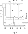
- the silo vehicle has a storage container 10 for binding agent.
- the storage container 10 has two openings 14 on an underside 12, which in the illustrated embodiment are each connected to a mechanical conveyor 18 via a funnel element 16, the conveyor 18 being a cellular wheel conveyor in the illustrated embodiment.
- the cellular wheel conveyors 18 are each connected to an intermediate chamber 20.
- binding agent passes through the openings 14 into the funnel elements 16. This takes place in particular by gravity, with a mechanical conveying device such as a screw conveyor or the like possibly additionally being provided in the storage container, for example around the binding agent from one of the opening 14 to transport the remote end of the storage container 10 to the opening 14.
- the binding agent slides through the funnel devices 16 into an upper conveying chamber, which is in position 24 ( Fig. 2 ) of the rotary feeder 18 is located.
- the bucket wheel conveyor 18 rotates about an axis 22 in FIG Fig. 2 in the direction of arrow 25.
- the binding agent reaches the intermediate chamber 20 due to gravity.
- the two conveying chambers in positions 32 and 34 which adjoin the conveying chamber in position 24 in the direction of rotation 25 are empty.
- the conveying chambers in positions 26 and 28 are already filled with binding agent and are emptied into the intermediate chamber 20 one after the other as the rotation continues in the direction of arrow 25 of the cell conveyor 18.
- compressed air is introduced into the intermediate chambers 20 by means of a conveying device, which in the illustrated embodiment is a compressor 36.
- the pressure in the intermediate chambers 20 is therefore higher than that of the surroundings.
- compressed air reaches the first intermediate chamber 20 in the conveying direction. Since the first intermediate chamber 20 in the conveying direction is connected via a connecting line 46 to the second intermediate chamber 20 in the conveying direction, there is also increased pressure in this.
- the corresponding compressed air also reaches the delivery chamber of the cellular wheel conveyor 18, which is in position 30. There is thus an increased pressure in the chamber in position 32.
- the pressure which is also initially increased in the chamber in position 34, is discharged via a pressure relief device.
- the pressure relief device comprises at least one channel or line 40 which is connected to an area of the mechanical conveying device 18 in that the emptied conveying chamber, for example in the area of position 34, is not connected to the intermediate chamber 20 or to the storage container 10.
- a valve 41 in particular a check valve, can be provided in the line 40, in particular in the area in which the line 40 is connected to the cellular wheel conveyor 18.
- the pressure relief device 40, 41 is therefore connected to the storage container 10, so that any binding agent present in the line 40 is conveyed back into the storage container 10.
- the storage container 10 has an overpressure outlet 44 connected to a filter 42.
- the line 40 is connected to the storage container 10 in an upper region thereof.
- first intermediate chamber 20 For conveying the binding agent to the spreading device or a buffer container 52 ( Fig. 3 ) of the spreading device, air under pressure is supplied to the first intermediate chamber 20 in the conveying direction with the aid of the compressor 36 via the pressure line 38.
- the first intermediate chamber 20 is connected via the connecting line 46 to the second intermediate chamber 20 in the flow direction, so that binding agent is conveyed from the first intermediate chamber 20 through the connecting line 46 into the second intermediate chamber 20.
- the second intermediate chamber 20 in the flow direction is connected to the spreading device or the buffer container 52 of the spreading device via a conveying line 48.
- a bypass line 50 bridging the two intermediate chambers 20 is connected to the pressure line 38 in the flow direction upstream of the first intermediate chamber 20 and which is connected to the delivery line 48 after the second intermediate chamber 20 in the flow direction.
- the bypass line 50 is connected to the connecting line 46 via a branch line 51.
- a particularly controllable valve can be arranged, for example, in the bypass line 50 and / or in the branch line.
- the pneumatic conveying device thus comprises a compressed air source, which in the illustrated embodiment is a Compressor 36 acts and lines.
- the pneumatic conveying device can have the lines 46, 50, 51 and 48.
- the pneumatic conveying device is subjected to pressure from a pressure source, in the exemplary embodiment the compressor 36.
- a pressure source in the exemplary embodiment the compressor 36.
- the conveying chambers are connected to the intermediate container 20 and thus to the pneumatic conveying device, which has excess pressure in relation to the surroundings, in an air-permeable manner.
- the air pressure in the conveying chambers in positions 30 and 32 is also higher than that of the surroundings. In the conveying chamber in position 30 there is increased air pressure due to the currently existing air-permeable connection to the pneumatic conveying device.
- the pressure relief device 40, 41 is provided on the mechanical conveying device 18 in the position 34.
- Silo vehicle 54 shown is via the conveyor line 48 with the in Figure 3 soil cultivating machine 56 shown.
- the soil working machine 56 has the buffer container 52, which is connected to the conveying line 48 and serves for the intermediate buffering of binding agent.
- a scattering device 58 is connected to the buffer container 52. Binder is scattered via the scattering device 58 onto a surface 60 of a ground to be milled, such as a road surface. The surface 60 is then removed with the aid of a milling and mixing rotor 62.
- Such a soil cultivating machine with a buffer container 52 is shown in, for example DE 10 2009 008 884 described.
Landscapes
- Engineering & Computer Science (AREA)
- Structural Engineering (AREA)
- Civil Engineering (AREA)
- Life Sciences & Earth Sciences (AREA)
- Architecture (AREA)
- General Life Sciences & Earth Sciences (AREA)
- Environmental & Geological Engineering (AREA)
- Soil Sciences (AREA)
- Agronomy & Crop Science (AREA)
- Mining & Mineral Resources (AREA)
- Paleontology (AREA)
- General Engineering & Computer Science (AREA)
- Mechanical Engineering (AREA)
- Health & Medical Sciences (AREA)
- Public Health (AREA)
- Transportation (AREA)
- Filling Or Emptying Of Bunkers, Hoppers, And Tanks (AREA)
- Air Transport Of Granular Materials (AREA)
Description
- Die Erfindung betrifft ein Silofahrzeug zur Bereitstellung von Bindemitteln zur Bodenstabilisierung für eine Streueinrichtung gemäß dem Oberbegriff des unabhängigen Anspruchs 1.
- Ferner betrifft die Erfindung einen Arbeitszug zur Bearbeitung von Böden mit einer selbstfahrenden Bodenbearbeitungsmaschine sowie einem Silofahrzeug.
- Mit Hilfe von insbesondere pulverförmigem Bindemittel, wie bspw. Kalk oder Zement, kann ein Verbessern bzw. Verfestigen von Böden erfolgen. Hierzu wird das Bindemittel in den Boden eingebracht, um insbesondere dessen Tragfähigkeit zu erhöhen. Eine Bodenstabilisierung erfolgt insbesondere beim Bau von Straßen oder Schienenwegen, sowie beim Bau von Industrieflächen.
- Zum Ausbringen von Bindemittel, sind Bindemittelstreuer bekannt. Derartige Fahrzeuge weisen einen großen Behälter zur Aufnahme von Bindemittel auf. Das Ausbringen von Bindemittel erfolgt derart, dass das Streufahrzeug dem Stabilisierer oder Recycler vorausfährt. Durch den Stabilisierer oder Recycler wird beispielsweise mit Hilfe einer Fräs-/Mischwalze eine obere Schicht einer zu befestigenden Fläche abgefräst, das abgefräste Material wird ggf. mit weiterem Material vermischt und wieder ausgebracht. Das von dem Bindemittelstreuer vor dem Stabilisierer oder Recycler ausgebrachte Bindemittel wird hierbei mit aufgenommen. Nachteilig bei derartigen vorausfahrenden Bindemittelstreuern ist, dass das Bindemittel verweht werden kann. Dies erhöht die Kosten auf Grund des erhöhten Materialbedarfs und führt zu Staubbelastungen für die Arbeiter und Anwohner.
- Ferner sind Stabilisierer und Recycler bekannt, die einen Bindemittelsteuer aufweisen. Ein derartiger Stabilisierer oder Recycler mit integriertem Bindemittelstreuer ist bspw. aus
DE 10 2009 008 884 bekannt. Hierdurch ist es möglich, das Bindemittel bspw. unmittelbar vor dem Fräs-/Mischrotor auszubringen, sodass das Bindemittel unmittelbar von dem Fräs-/Mischrotor aufgenommen wird. Hierbei besteht die Gefahr des Verwehens nicht. Andererseits weisen derartige Stabilisierer oder Recycler mit integriertem Bindemittelbehälter den Nachteil auf, dass ein derartiger Bindemittelbehälter ein geringes Füllvolumen aufweist und daher regelmäßig befüllt werden muss. Das Befüllen eines derartigen Bindemittelbehälters erfolgt durch ein Silofahrzeug. Aus dem Silofahrzeug wird in regelmäßigen Abständen Bindemittel dem Bindemittelbehälter des Stabilisierers oder Recyclers zugeführt. Das Zuführen erfolgt bspw. pneumatisch. Hierzu wird der Bindemittelbehälter des Silofahrzeugs zur Befüllung unter Druck gesetzt. Ein Befüllen des Behälters des Stabilisierers oder Recyclers während der Fahrt ist nur eingeschränkt möglich. - Aus
DE 20 2008 012 104 ist ein Arbeitszug, bestehend aus einem Silofahrzeug und einem Fräsfahrzeug bekannt. Das Fräsfahrzeug weist einen Vorratsbehälter für ein Schüttgut, wie ein Bindemittel auf. Dieser weist ein kleines Volumen auf und wird insofern permanent von dem Silofahrzeug befüllt. Das Silofahrzeug ist hierbei derart aufgebaut, dass nicht der gesamte Bindemittelbehälter des Silofahrzeugs unter Druck gesetzt werden muss. Vielmehr ist in dem Bindemittelbehälter des Silofahrzeugs eine mechanische Transporteinrichtung angeordnet, die das Schüttgut bspw. Mittels einer Förderschnecke in eine Kammer fördert. Aus der Kammer wird das Schüttgut sodann pneumatisch über eine Transportleitung zu dem Vorratsbehälter des Fräsfahrzeugs gefördert. Nachteilig ist hierbei allerdings, dass durch die pneumatische Förderung ein Aufwirbeln des Bindemittels auch in dem Bindemittelbehälter des Silofahrzeugs erfolgt. Dies kann zu einer ungleichmäßigen Zuführung an Bindemittel zu dem Vorratsbehälter des Fräsfahrzeugs führen. Ferner besteht der Nachteil, dass innerhalb des Silofahrzeugs eine erhöhte Staubentwicklung entsteht. Dies führt zu höheren Belastungen der Filteranlagen und kann ferner auch Störungen bei Sensoren, insbesondere innerhalb des Silofahrzeugs angeordneter Füllstandssensoren, hervorrufen. - Aus
DE 29 39 648 ist ein Silofahrzeug mit den Merkmalen des Oberbegriffs des Anspruchs 1 bekannt. - Aufgabe der Erfindung ist es, ein Silofahrzeug zur Bereitstellung von Bindemittel zur Bodenstabilisierung für eine Streueinrichtung zu schaffen, mit der eine zuverlässige Bindemittelzufuhr möglich ist sowie einen entsprechenden Arbeitszug zu schaffen.
- Die Lösung der Aufgabe erfolgt erfindungsgemäß durch ein Silofahrzeug gemäß Anspruch 1 sowie einen Arbeitszug zur Bearbeitung von Böden, wie Straßen, Schienenwegen, Industrieflächen etc. mit einer Bodenbearbeitungsmaschine und einem Arbeitszug nach Anspruch 11.
- Mit Hilfe des Silofahrzeugs erfolgt insbesondere ein Befüllen eines Bindemittelbehälters einer Bodenbearbeitungsmaschine wie eines Stabilisierers oder Recyclers, wie beispielsweise in
DE 10 2009 008 884 beschrieben. Das erfindungsgemäße Silofahrzeug zur Bereitstellung von Bindemittel zur Bodenstabilisierung bei einer Streueinrichtung weist einen Vorratsbehälter für das Bindemittel auf. Mit dem Vorratsbehälter ist eine mechanische Fördereinrichtung verbunden. Mit Hilfe der Fördereinrichtung erfolgt ein Fördern des Bindemittels aus dem Vorratsbehälter in eine Zwischenkammer. Mit der Zwischenkammer ist eine pneumatische Fördereinrichtung verbunden. Mit Hilfe der pneumatischen Fördereinrichtung wird das Bindemittel zu der Streueinrichtung gefördert, wobei die Streueinrichtung insbesondere einen Vorratsbehälter, bzw. Zwischenpuffer aufweist. Die Streueinrichtung ist insbesondere unmittelbar an einer Bodenbearbeitungsmaschine vorgesehen. Erfindungsgemäß ist mit der mechanischen Fördereinrichtung eine Druckentlastungseinrichtung verbunden. Durch die Druckentlastungseinrichtung ist im Wesentlichen ein Eindringen von Druckluft in einen Bereich des Vorratsbehälters des Silofahrzeugs vermieden, in dem ein Aufwirbeln des Bindemittels in dem Vorratsbehälter des Silofahrzeugs eine zuverlässige Förderung beeinträchtigen würde. - Bei der Druckentlastungseinrichtung kann es sich um ein mit der mechanischen Fördereinrichtung verbundenes Ventil handeln. Über das Ventil kann ggf. in der mechanischen Fördereinrichtung entstehender Druck reduziert, bzw. Druckluft abgeführt werden. Die entsprechende Druckluft kann unmittelbar in die Umgebung abgeführt werden, wobei es bevorzugt ist, dass eine Filtereinrichtung vorgesehen ist, um ein Austreten von Bindemittel zu vermeiden. Insbesondere beim Vorsehen einer Filtereinrichtung ist es nicht unbedingt erforderlich zusätzlich ein Ventil vorzusehen. Eine entsprechende Auslassöffnung in der mechanischen Fördereinrichtung durch die Druckluft entweichen kann, ist ausreichend.
- Bei der mechanischen Fördereinrichtung handelt es sich bspw. um einen Schwerkraftförderer. Hierbei kann insbesondere ein Fördern des Bindemittels aufgrund des Eigengewichts erfolgen, wobei das Fördern des Bindemittels bspw. auch durch einen Schneckenförderer oder dergleichen unterstützt werden kann.
- Um ein Aufwirbeln von Streumittel durch Eindringen der Druckluft in den Vorratsbehälter des Silofahrzeugs in einem Aufwirbelungen hervorrufenden Bereich, wie insbesondere in dem Bereich der Abfuhr des Streumittels zu vermeiden, ist es besonders bevorzugt, dass die mechanische Fördereinrichtung eine Förderkammer aufweist. Hierbei kann bspw. eine Fördereinrichtung entsprechend einer Schleuse ausgebildet sein. So kann über entsprechende Schieber eine Öffnung zu dem Vorratsbehälter geöffnet und geschlossen werden und über weitere Schieber kann eine Verbindung zwischen der Förderkammer und der Zwischenkammer geöffnet und geschlossen werden. Entsprechend einer Schleuse kann die Förderkammer somit zunächst durch Öffnen des entsprechenden Schiebers aus dem Vorratsbehälter mit Bindemittel befüllt werden, wobei die Schieber sodann geschlossen wird bevor der die Öffnung zur Zwischenkammer verschließende Schieber geöffnet wird. Hierdurch dringt aus der Zwischenkammer stets nur Druck in die Förderkammer ein. Die Förderkammer ist sodann erfindungsgemäß mit der Druckentlastungseinrichtung verbunden, sodass der Druck in der Förderkammer reduziert werden kann, bevor durch das Betätigen des entsprechenden Schiebers die Schleuse wieder mit dem Vorratsbehälter zum Befüllen mit Bindemittel verbunden wird.
- In besonders bevorzugter Ausführungsform handelt es sich bei der mechanischen Fördereinrichtung um einen Zellenradförderer. Dieser weist insbesondere mehrere, um eine Drehachse angeordnete Förderkammern auf. In eine in Richtung des Vorratsbehälters, offene Förderkammer gelangt Bindemittel unter Schwerkraft oder mit Hilfe einer weiteren Fördereinrichtung. Die entsprechende Förderkammer wird sodann durch den Zellenradbeförderer weitergedreht bis das sich in der entsprechenden Kammer befindliche Bindemittel aus dieser, aufgrund der Schwerkraft, in die Zwischenkammer gelangt. Mit Hilfe eines Zellenradförderers ist es insbesondere möglich ein kontinuierliches Fördern von Bindemittel von mehreren um eine Drehachse angeordneten Förderkammern zu realisieren. In eine mit der Zwischenkammer verbundene Förderkammer gelangt Druckluft, bzw. der Druck in dieser Förderkammer erhöht sich. Bevor diese Förderkammer wieder mit dem Vorratsbehälter verbunden wird, erfolgt mit Hilfe der Druckentlastungseinrichtung eine Druckreduzierung in dieser Förderkammer. Hierzu wird beim Weiterdrehen des Zellenradförderers die Verbindung der entsprechenden Förderkammer mit der Zwischenkammer unterbrochen. In dieser Lage erfolgt die Druckentlastung.
- Unabhängig von der Art der verwendeten Fördereinrichtung ist es daher besonders bevorzugt, dass die Druckentlastungseinrichtung in einem Bereich angeordnet ist, in dem eine diesen Bereich passierende Förderkammer, weder mit dem Vorratsbehälter noch mit der Zwischenkammer verbunden ist.
- Erfindungsgemäß ist die Druckentlastungseinrichtung über eine Entlüftungsleitung mit dem Vorratsbehälter verbunden. Die Druckentlastungseinrichtung kann lediglich durch die Verbindung der mechanischen Fördereinrichtung über eine Entlüftungsleitung mit dem Vorratsbehälter ausgebildet sein. Ggf. kann in der Entlüftungsleitung zusätzlich ein Ventil vorgesehen sein. Vorzugsweise ist die Entlüftungsleitung mit einem Bereich des Vorratsbehältnisses verbunden indem durch Einleiten von Luft entweder keine Aufwirbelungen von Bindemittel auftreten oder diese nicht störend sind. Das Einleiten der Druckluft in den Vorratsbehälter erfolgt vorzugsweise in einem oberen und/oder einem von der mechanischen Fördereinrichtung entfernten Bereich des Vorratsbehälters.
- Vorzugsweise weist der Vorratsbehälter einen Überdruckauslass auf. Dieser weist vorzugsweise eine Filtereinrichtung auf, um ein Austreten von Bindemittel zu vermeiden. In bevorzugter Weiterbildung ist die Entlüftungsleitung der Druckentlastungseinrichtung mit dem Überdruckauslass, insbesondere unmittelbar verbunden. Hierdurch ist ein Auftreten von Verwirbelungen in dem Vorratsbehälter vermieden.
- Zum Fördern des Bindemittels aus der Zwischenkammer zu der Streueinrichtung, ist es bevorzugt, dass die pneumatische Fördereinrichtung eine Druckluftquelle, insbesondere einen Kompressor aufweist. Der Kompressor ist entweder unmittelbar oder über eine Druckleitung mit der Zwischenkammer verbunden. Das Verwenden eines Kompressors als pneumatische Fördereinrichtung, hat einerseits den Vorteil, dass hierdurch eine schnellere Förderung des Bindemittels aus der Zwischenkammer zu der Streueinrichtung realisiert werden kann und andererseits ein derartiger Kompressor üblicherweise bei Silofahrzeugen insbesondere zur Reinigung vorhanden ist.
- Bei einer weiteren bevorzugten Ausführungsform ist der Vorratsbehälter des Silofahrzeugs mit mehreren mechanischen Fördereinrichtungen verbunden. Vorzugsweise sind ggf. mehrere separate Zwischenkammern vorgesehen, wobei ggf. jede Zwischenkammer mit einer gesonderten mechanischen Fördereinrichtung verbunden ist. Insbesondere weist jede mechanische Fördereinrichtung eine separate Druckentlastungseinrichtung auf.
- Beim Vorsehen mehrerer Zwischenkammern sind diese vorzugsweise bezüglich der pneumatischen Beförderung in Reihe angeordnet. Das Bindemittel wird somit in bevorzugter Ausführungsform bspw. von einer ersten Zwischenkammer zunächst in eine zweite Zwischenkammer gefördert und sodann von dieser zur Streueinrichtung. Ferner ist auch ein zueinander paralleles Anordnen mehrerer Zwischenkammern möglich.
- Bei einer bevorzugten Weiterbildung der Erfindung weist das Silofahrzeug ferner eine die mindestens eine Zwischenkammer umgehende pneumatische Bypassleitung auf. Diese zweigt einerseits insbesondere von der Druckleitung, d.h. der Leitung zwischen der Druckluftquelle und der Zwischenkammer ab und ist andererseits mit der Förderleitung, d.h. der von der mindestens einen Zwischenkammer zur Streueinrichtung führenden Leitung verbunden. Hierdurch ist es möglich in der Förderleitung einen höheren Druckluftstrom, bzw. höheren Druck zu erzeugen und somit ein sicheres Zuführen eines Bindemittels zu der Streueinrichtung zu gewährleisten. Auch kann die Bypassleitung beim Vorsehen mehrerer Zwischenkammern ggf. nur eine Zwischenkammer überbrücken. Ferner sind auch mehrere Bypassleitungen möglich, die jeweils eine oder mehrere Zwischenkammern überbrücken. Auch Abzweigungen in einer mehrere Zwischenkammern überbrückende Bypassleitung, die sodann mit einer Leitung verbunden ist, die zwei benachbarte Zwischenkammern verbindet, ist möglich. Die eine oder mehreren Bypassleitungen können vorzugsweise teilweise oder ganz abschaltbar, bzw. regelbar sein, sodass so eine Aufteilung der Menge an Druckluft möglich ist, die durch die mindestens eine Zwischenkammer bzw. durch die mindestens eine Bypassleitung geleitet wird. Selbstverständlich können unterschiedliche Bypassleitungen und/oder Abzweigungen der Bypassleitungen jeweils mit gesondert regelbaren Ventilen versehen sein.
- Desweiteren betrifft die Erfindung einen Arbeitszug zur Bearbeitung von Böden, bei denen es sich bspw. um Straßen, Schienenwege, Industrieflächen oder dergleichen handelt. Der Arbeitszug weist eine insbesondere selbstfahrende Bodenbearbeitungsmaschine wie ein Stabilisierer oder Recycler auf. Die Bodenbearbeitungsmaschine weist in einem Rotorgehäuse einen Fräs-/Mischrotor auf. Ferner weist die Bodenbearbeitungsmaschine eine Streueinrichtung zum Ausbringen von Bindemittel auf. Die Streueinrichtung ist mit dem Silofahrzeug verbunden, sodass von dem Silofahrzeug der Streueinrichtung Bindemittel, insbesondere während des Betriebs, zugeführt werden kann. Das Silofahrzeug ist hierbei wie vorstehend beschrieben ausgebildet und vorzugsweise vorteilhaft weitergebildet. Vorzugsweise weist die Streueinrichtung einen Pufferbehälter für Bindemittel auf, wobei sodann der Pufferbehälter über die Förderleitung mit dem Silofahrzeug, bzw. der mindestens einen Zwischenkammer verbunden ist. Der maximale Förderstrom des Bindemittels in der Förderleitung, die mit dem Pufferbehälter der Bodenbearbeitungsmaschine verbunden ist, beträgt vorzugsweise wenigstens 400 kg/min und insbesondere wenigstens 550 kg/min. Die Fördermenge ist insbesondere an die Anforderungen bzw. den Verbrauch anpassbar.
- Eine Steuerung der Befüllung des Pufferbehälters erfolgt vorzugsweise ausgehend von der Bodenbearbeitungsmaschine. Dies kann beispielsweise durch entsprechende Füllstandssensoren in dem Pufferbehälter erfolgen. Die Befüllung des Pufferbehälters kann hierbei permanent oder intermittierend erfolgen.
- Nachfolgend wird die Erfindung anhand einer bevorzugten Ausführungsform unter Bezugnahme auf die anliegenden Zeichnungen näher erläutert.
- Es zeigen:
- Fig. 1:
- eine schematische Rückansicht eines Silofahrzeugs,
- Fig. 2:
- eine schematische Schnittansicht entlang der Linie II-II in
Fig.1 und - Fig. 3
- eine schematische Seitenansicht einer Bodenbearbeitungsmaschine.
- Das Silofahrzeug weist einen Vorratsbehälter 10 für Bindemittel auf. Der Vorratsbehälter 10 weist an einer Unterseite 12 zwei Öffnungen 14 auf, die im dargestellten Ausführungsbeispiel jeweils über ein Trichterelement 16 mit jeweils einer mechanischen Fördereinrichtung 18 verbunden sind, wobei es sich im dargestellten Ausführungsbeispiel bei der Fördereinrichtungen 18 um Zellenradförderer handelt. Die Zellenradförderer 18 sind jeweils mit einer Zwischenkammer 20 verbunden.
- Aus dem Vorratsbehälter 10 gelangt Bindemittel durch die Öffnungen 14 in die Trichterelemente 16. Dies erfolgt insbesondere durch Schwerkraft, wobei ggf. zusätzlich in dem Vorratsbehälter eine mechanische Fördereinrichtung, wie ein Schneckenförderer oder dergleichen vorgesehen sein kann, beispielsweise um das Bindemittel von einem von der Öffnung 14 ferngelegenen Ende des Vorratsbehälters 10 zu der Öffnung 14 zu transportieren. Das Bindemittel rutscht durch die Trichtereinrichtungen 16 in eine obere Förderkammer, die sich in der Position 24 (
Fig. 2 ) des Zellenradförderers 18 befindet. Der Zellenradförderer 18 rotiert um eine Achse 22 inFig. 2 in Richtung des Pfeils 25. Hierdurch werden nach der Kammer in Position 24 die gerade mit Bindemittel befüllt wird, die Kammern in den Positionen 34 und 32 mit Bindemittel gefüllt. Aus der Förderkammer in Position 30, die der Förderkammer in Position 24 gegenüberliegend angeordnet ist, gelangt das Bindemittel aufgrund der Schwerkraft in die Zwischenkammer 20. Die sich in Rotationsrichtung 25 an die Förderkammer in Position 24 anschließenden beiden Förderkammern in den Positionen 32 und 34, sind leer. Die Förderkammern in den Positionen 26 und 28 sind bereits mit Bindemittel befüllt und werden bei fortschreitender Rotation in Richtung des Pfeils 25 des Zellenförderers 18 nacheinander in die Zwischenkammer 20 entleert. - Für die pneumatische Förderung des Bindemittels wird mittels einer Fördereinrichtung, bei der es sich im dargestellten Ausführungsbeispiel um einen Kompressor 36 handelt, Druckluft in die Zwischenkammern 20 eingebracht. In den Zwischenkammern 20 herrscht somit ein gegenüber der Umgebung erhöhter Druck. Über die mit dem Kompressor 36 verbundene Druckleitung 38 gelangt Druckluft in die in Förderrichtung erste Zwischenkammer 20. Da die in Förderrichtung erste Zwischenkammer 20 über eine Verbindungsleitung 46 mit der in Förderrichtung zweiten Zwischenkammer 20 verbunden ist, herrscht auch in dieser erhöhter Druck. Die entsprechende Druckluft gelangt auch in die Förderkammer des Zellenradförderers 18, die sich in der Position 30 befindet. In der Kammer in Position 32 herrscht somit ein erhöhter Druck. Der auch in der Kammer in Position 34 zunächst erhöhte Druck wird über eine Druckentlastungseinrichtung abgeführt. Die Druckentlastungseinrichtung umfasst im dargestellten Ausführungsbeispiel zumindest einen Kanal oder eine Leitung 40, die mit einem Bereich der mechanischen Fördereinrichtung 18 verbunden ist, indem die entleerte Förderkammer, beispielsweise im Bereich der Position 34 weder mit der Zwischenkammer 20 noch mit dem Vorratsbehälter 10 verbunden ist. Ggf. kann in der Leitung 40 insbesondere in dem Bereich in dem die Leitung 40 mit dem Zellenradförderers 18 verbunden ist, ein Ventil 41 insbesondere ein Rückschlagventil vorgesehen sein.
- Da ggf. in der Kammer in Position 34 noch Reste an Bindemittel vorhanden sein können, können diese in die Druckentlastungseinrichtung 40, 41 gelangen. Die Druckentlastungseinrichtung 40, 41 ist daher mit dem Vorratsbehälter 10 verbunden, sodass ggf. in der Leitung 40 vorhandenes Bindemittel zurück in den Vorratsbehälter 10 gefördert wird. Um das Entstehen von Überdruck in dem Vorratsbehälter 10 zu vermeiden, weist der Vorratsbehälter 10 einen mit einem Filter 42 verbundenen Überdruckauslass 44 auf. Um ein Verwirbeln von Bindemitteln in dem Vorratsbehälter 10 zu vermeiden, ist die Leitung 40 in einem oberen Bereich des Vorratsbehälters 10 mit diesem verbunden.
- Zum Fördern des Bindemittels zu der Streueinrichtung, bzw. einem Pufferbehälter 52 (
Fig. 3 ) der Streueinrichtung, wird mit Hilfe des Kompressors 36 über die Druckleitung 38 unter Druck stehende Luft der in Förderrichtung ersten Zwischenkammer 20 zugeführt. Die erste Zwischenkammer 20 ist über die Verbindungsleitung 46 mit der in Strömungsrichtung zweiten Zwischenkammer 20 verbunden, sodass Bindemittel aus der ersten Zwischenkammer 20 durch die Verbindungsleitung 46 in die zweite Zwischenkammer 20 gefördert wird. Die in Strömungsrichtung zweite Zwischenkammer 20 ist über eine Förderleitung 48 mit der Streueinrichtung, bzw. dem Pufferbehälter 52 der Streueinrichtung verbunden. - Ferner ist in Strömungsrichtung vor der ersten Zwischenkammer 20 mit der Druckleitung 38 eine die beiden Zwischenkammern 20 überbrückende Bypassleitung 50 verbunden, die in Strömungsrichtung nach der zweiten Zwischenkammer 20 mit der Förderleitung 48 verbunden ist. Über eine Abzweigleitung 51 ist die Bypassleitung 50 mit der Verbindungsleitung 46 verbunden. Zur Regelung der Aufteilung der Druckluft kann beispielsweise in der Bypassleitung 50 und /oder in der Abzweigleitung ein insbesondere regelbares Ventil angeordnet sein.
- Je nach Ausgestaltung umfasst die pneumatische Fördereinrichtung somit eine Druckluftquelle, bei der es sich im dargestellten Ausführungsbeispiel um einen Kompressor 36 handelt und Leitungen. Neben der Druckluftleitung 38 kann die pneumatische Fördereinrichtung die Leitungen 46, 50, 51 und 48 aufweisen.
- Zur Förderung des Bindemittels wird die pneumatische Fördereinrichtung mit Druck aus einer Druckquelle, im Ausführungsbeispiel dem Kompressor 36 beaufschlagt. Dies führt zu einem gegenüber der Umgebung erhöhten Druck in der Fördereinrichtung. Zur Übergabe des Bindemittels von den Förderkammern in den Zwischenbehälter 20 werden die Förderkammern luftdurchlässig mit dem Zwischenbehälter 20 und damit der gegenüber der Umgebung Überdruck aufweisenden pneumatischen Fördereinrichtung verbunden. Somit herrscht im dargestellten Ausführungsbeispiel in den Förderkammern in Position 30 und 32 ebenfalls gegenüber der Umgebung erhöhter Luftdruck. In der Förderkammer in Position 30 herrscht erhöhter Luftdruck aufgrund der aktuell vorhandenen luftdurchlässigen Verbindung zur pneumatischen Fördereinrichtung. In der Förderkammer in Position 32 wurde der Druck erhöht als diese zur Bindemittelabgabe luftdurchlässig mit der Zwischenkammer 20 verbunden war. Bei fortschreitender Rotation der Zellenradschleuse 18 wurde diese luftdurchlässige Verbindung unterbrochen, der vorhandene Druck kann jedoch nicht abgebaut werden. In der Position 34 befindet ist an der mechanischen Fördereinrichtung 18 erfindungsgemäß die Druckentlastungseinrichtung 40, 41 vorgesehen.
- Das in
Figur 2 dargestellte Silofahrzeug 54 ist über die Förderleitung 48 mit der inFigur 3 dargestellten Bodenbearbeitungsmaschine 56 verbunden. Die Bodenbearbeitungsmaschine 56 weist den Pufferbehälter 52 auf, der mit der Förderleitung 48 verbunden ist und zum Zwischenpuffern von Bindemittel dient. Mit dem Pufferbehälter 52 ist eine nicht näher dargestellte Streueinrichtung 58 verbunden. Über die Streueinrichtung 58 wird Bindemittel auf eine Oberfläche 60 eines abzufräsenden Bodens, wie einer Straßenoberfläche, gestreut. Die Oberfläche 60 wird sodann mit Hilfe eines Fräs- und Mischrotors 62 abgetragen. Eine derartige Bodenbearbeitungsmaschine mit Pufferbehälter 52 ist beispielsweise inDE 10 2009 008 884 beschrieben.
Claims (12)
- Silofahrzeug (54) zur Bereitstellung von Bindemitteln zur Bodenstabilisierung für eine Streueinrichtung, mit
einem Vorratsbehälter (10) für Bindemittel,
einer Zwischenkammer (20),
einer mit dem Vorratsbehälter (10) verbundenen mechanischen Fördereinrichtung (18) zum Fördern von Bindemitteln aus dem Vorratsbehälter (10) in die Zwischenkammer (20),
einer mit der Zwischenkammer (20) verbundenen pneumatischen Fördereinrichtung (36) zum Fördern des Bindemittels zu der Streueinrichtung und
einer Druckentlastungseinrichtung (40, 41) die mit der mechanischen Fördereinrichtung (18) verbunden ist,
dadurch gekennzeichnet, dass
eine Entlüftungsleitung der Druckentlastungseinrichtung (40, 41) mit dem Vorratsbehälter (10) verbunden ist. - Silofahrzeug (54) nach Anspruch 1, dadurch gekennzeichnet, dass die mechanische Fördereinrichtung (18) als Schwerkraftförderer ausgebildet ist.
- Silofahrzeug (54) nach Anspruch 1 oder 2, dadurch gekennzeichnet, dass die mechanische Fördereinrichtung (18) Förderkammern (24, 26, 28, 30, 32, 34) aufweist und vorzugsweise als Zellenradförderer ausgebildet ist.
- Silofahrzeug (54) nach Anspruch 3, dadurch gekennzeichnet, dass die Druckentlastungseinrichtung (40, 41) in einem Bereich mit der mechanischen Fördereinrichtung (18) verbunden ist, in dem eine diesen Bereich passierende Förderkammer (34) weder mit dem Vorratsbehälter (10) noch mit der Zwischenkammer (20) verbunden ist.
- Silofahrzeug (54) nach Ansprüchen 1 bis 4, dadurch gekennzeichnet, dass der Vorratsbehälter (10) einen Überdruckauslass (44) mit Filtereinrichtung (42) aufweist.
- Silofahrzeug (54) nach Anspruch 5, dadurch gekennzeichnet,
dass die Druckentlastungseinrichtung, insbesondere über eine Leitung (40) mit dem Überdruckauslass (44) verbunden ist. - Silofahrzeug (54) nach Ansprüchen 1 bis 6, dadurch gekennzeichnet, dass die pneumatische Fördereinrichtung (36) einen Kompressor aufweist, der insbesondere über eine Druckleitung (38) mit der Zwischenkammer (20) verbunden ist.
- Silofahrzeug (54) nach Ansprüchen 1 bis 7, dadurch gekennzeichnet, dass der Vorratsbehälter (10) mit mindestens zwei mechanischen Fördereinrichtungen (18) verbunden ist.
- Silofahrzeug (54) nach Anspruch 8, dadurch gekennzeichnet, dass jede mechanische Fördereinrichtung (18) mit einer separaten Zwischenkammer (20) verbunden ist, wobei die Zwischenkammern (20) vorzugsweise bezüglich der pneumatischen Fördereinrichtung in Reihe angeordnet sind.
- Silofahrzeug (54) nach Ansprüchen 1 bis 9, dadurch gekennzeichnet, dass eine, die mindestens eine Zwischenkammer (20) umgehende pneumatische Bypassleitung (50) vorgesehen ist, die mit einer Förderleitung (48) zum Zuführen des Bindemittels zu der Streueinrichtung verbunden ist.
- Arbeitszug zur Bearbeitung von Böden, mit
einer selbstfahrenden Bodenbearbeitungsmaschine mit einem in einem Rotorgehäuse angeordneten Fräs-/Mischrotor und einer Streueinrichtung zum Ausbringen von Bindemittel und
einem Silofahrzeug (54) nach einem der Ansprüche 1 bis 10 zum Zuführen von Bindemitteln zur Streueinrichtung. - Arbeitszug nach Anspruch 11, dadurch gekennzeichnet, dass die Streueinrichtung einen Pufferbehälter für Bindemittel aufweist, der mit der Förderleitung (48) des Silofahrzeugs verbunden ist.
Applications Claiming Priority (1)
| Application Number | Priority Date | Filing Date | Title |
|---|---|---|---|
| DE102017223698.1A DE102017223698A1 (de) | 2017-12-22 | 2017-12-22 | Silofahrzeug, Fördersystem für ein Silofahrzeug sowie Arbeitszug |
Publications (3)
| Publication Number | Publication Date |
|---|---|
| EP3505681A2 EP3505681A2 (de) | 2019-07-03 |
| EP3505681A3 EP3505681A3 (de) | 2019-09-25 |
| EP3505681B1 true EP3505681B1 (de) | 2021-05-26 |
Family
ID=64745937
Family Applications (1)
| Application Number | Title | Priority Date | Filing Date |
|---|---|---|---|
| EP18213633.3A Active EP3505681B1 (de) | 2017-12-22 | 2018-12-18 | Silofahrzeug und arbeitszug |
Country Status (4)
| Country | Link |
|---|---|
| US (2) | US10619322B2 (de) |
| EP (1) | EP3505681B1 (de) |
| CN (2) | CN109958031B (de) |
| DE (1) | DE102017223698A1 (de) |
Families Citing this family (3)
| Publication number | Priority date | Publication date | Assignee | Title |
|---|---|---|---|---|
| DE102017223698A1 (de) * | 2017-12-22 | 2019-06-27 | Wirtgen Gmbh | Silofahrzeug, Fördersystem für ein Silofahrzeug sowie Arbeitszug |
| DE102019115196A1 (de) | 2019-06-05 | 2020-12-10 | Wirtgen Gmbh | Silofahrzeug, Fördersystem für ein Silofahrzeug, Arbeitszug sowie Verfahren zum Fördern von Bindemittel für einen Arbeitszug |
| CN110700047B (zh) * | 2019-11-05 | 2024-12-10 | 达刚控股集团股份有限公司 | 一种粉料撒布车上装 |
Family Cites Families (8)
| Publication number | Priority date | Publication date | Assignee | Title |
|---|---|---|---|---|
| DE2939648C2 (de) * | 1979-09-29 | 1986-06-26 | Spitzer Silo-Fahrzeugwerk GmbH & Co KG, 6957 Elztal | Fahrzeug zum Transport und zum Entleeren eines Schüttgutcontainers |
| DE3910617A1 (de) * | 1989-04-01 | 1990-10-04 | Hoechst Ag | Zellenradschleuse |
| DE202008012104U1 (de) | 2008-09-12 | 2010-02-11 | Bomag Gmbh | Arbeitszug mit einer Fräsvorrichtung |
| DE102009008884A1 (de) | 2009-02-14 | 2010-08-26 | Wirtgen Gmbh | Stabilisierer oder Recycler |
| AT509953B1 (de) | 2010-05-21 | 2012-06-15 | Kwb Kraft Und Waerme Aus Biomasse Gmbh | Zellenradschleuse |
| DE102012021421A1 (de) * | 2012-10-30 | 2014-04-30 | Bomag Gmbh | Arbeitszug mit einer fahrbaren Siloeinheit für Schüttgut und einem Fräsfahrzeug zum Einbringen von Schüttgut in den Bodenuntergrund, Fräsfahrzeug und Verfahren zum Überladen von Schüttgut von der fahrbaren Siloeinheit zum Fräsfahrzeug |
| US20170355534A1 (en) * | 2016-06-13 | 2017-12-14 | Baker Hughes Incorporated | Dry bulk pneumatic metering assembly and method |
| DE102017223698A1 (de) * | 2017-12-22 | 2019-06-27 | Wirtgen Gmbh | Silofahrzeug, Fördersystem für ein Silofahrzeug sowie Arbeitszug |
-
2017
- 2017-12-22 DE DE102017223698.1A patent/DE102017223698A1/de not_active Ceased
-
2018
- 2018-12-18 EP EP18213633.3A patent/EP3505681B1/de active Active
- 2018-12-18 US US16/223,164 patent/US10619322B2/en active Active
- 2018-12-20 CN CN201811564789.8A patent/CN109958031B/zh active Active
- 2018-12-20 CN CN201822147786.6U patent/CN209798483U/zh active Active
-
2020
- 2020-04-08 US US16/843,716 patent/US11098460B2/en active Active
Non-Patent Citations (1)
| Title |
|---|
| None * |
Also Published As
| Publication number | Publication date |
|---|---|
| US20190194896A1 (en) | 2019-06-27 |
| US20200291592A1 (en) | 2020-09-17 |
| EP3505681A2 (de) | 2019-07-03 |
| CN109958031A (zh) | 2019-07-02 |
| US11098460B2 (en) | 2021-08-24 |
| DE102017223698A1 (de) | 2019-06-27 |
| CN209798483U (zh) | 2019-12-17 |
| US10619322B2 (en) | 2020-04-14 |
| EP3505681A3 (de) | 2019-09-25 |
| CN109958031B (zh) | 2022-03-08 |
Similar Documents
| Publication | Publication Date | Title |
|---|---|---|
| DE102013226981B4 (de) | Baumaschine, sowie ein Verfahren zum Abfräsen und Abstransportieren eines abgefrästen Materialstroms einer Baumaschine | |
| EP3505681B1 (de) | Silofahrzeug und arbeitszug | |
| EP2218823B2 (de) | Stabilisierer oder Recycler | |
| DE102015212902A1 (de) | Fräsmaschine zum Bearbeiten von Bodenoberflächen, Übergabeeinrichtung, sowie Verfahren zur Übergabe von abgefrästem Material | |
| EP1939355B1 (de) | Gleisbaumaschine und Verfahren zur Gleissanierung | |
| EP0640719A2 (de) | Verfahren zum Stabilisieren eines Erdplanums | |
| DE202008012104U1 (de) | Arbeitszug mit einer Fräsvorrichtung | |
| EP2792228B1 (de) | Streuvorrichtung | |
| DE2856635A1 (de) | Maschine zum beschichten von abgefraesten oder abgeschaelten strassendecken | |
| EP3748083B1 (de) | Silofahrzeug, arbeitszug sowie verfahren zum fördern von bindemittel für einen arbeitszug | |
| EP1073798B1 (de) | Vorrichtung zum bearbeiten von fahrbahnen | |
| EP3053427A1 (de) | Pneumatische sämaschine | |
| EP1574620B1 (de) | Selbstfahrender kombinierter Betonzwangsmischer | |
| EP1798345B1 (de) | Schaufel für Ladefahrzeuge | |
| EP1219155A1 (de) | Streuvorrichtung | |
| DE19838979C1 (de) | Streugerät | |
| DE3938939A1 (de) | Vorrichtung zum aufbringen von bindemittel und abstreumaterial fuer den strassenbau | |
| DE102020120833B4 (de) | Anbauvorrichtung für einen Lastkraftwagen zum Aufbringen einer Deckschicht aus schüttfähigem Baumaterial auf einem Straßen- und/oder Wegeunterbau | |
| DE3316030A1 (de) | Verfahren und vorrichtung zur befeuchtung von koernigem oder pulverfoermigen streugut | |
| DE4330246A1 (de) | Prallmühlenanlage | |
| DE20114300U1 (de) | Einstreumischfahrzeug | |
| DE2058132A1 (de) | Vorrichtung zum Streuen von pulverfoermigen Stoffen | |
| DE2858139C2 (de) | Verfahren zum Aufhalden von Waschbergen | |
| DE69016010T2 (de) | Mischtransportapparat für Bodenmörtel und dergleichen. | |
| AT226763B (de) | Vorrichtung zum gleichmäßigen Verteilen von Schüttgütern, z. B. Schotter, Splitt oder Sand, insbesondere für Straßenbauzwecke |
Legal Events
| Date | Code | Title | Description |
|---|---|---|---|
| PUAI | Public reference made under article 153(3) epc to a published international application that has entered the european phase |
Free format text: ORIGINAL CODE: 0009012 |
|
| STAA | Information on the status of an ep patent application or granted ep patent |
Free format text: STATUS: THE APPLICATION HAS BEEN PUBLISHED |
|
| AK | Designated contracting states |
Kind code of ref document: A2 Designated state(s): AL AT BE BG CH CY CZ DE DK EE ES FI FR GB GR HR HU IE IS IT LI LT LU LV MC MK MT NL NO PL PT RO RS SE SI SK SM TR |
|
| AX | Request for extension of the european patent |
Extension state: BA ME |
|
| PUAL | Search report despatched |
Free format text: ORIGINAL CODE: 0009013 |
|
| AK | Designated contracting states |
Kind code of ref document: A3 Designated state(s): AL AT BE BG CH CY CZ DE DK EE ES FI FR GB GR HR HU IE IS IT LI LT LU LV MC MK MT NL NO PL PT RO RS SE SI SK SM TR |
|
| AX | Request for extension of the european patent |
Extension state: BA ME |
|
| RIC1 | Information provided on ipc code assigned before grant |
Ipc: E01C 19/20 20060101AFI20190822BHEP |
|
| STAA | Information on the status of an ep patent application or granted ep patent |
Free format text: STATUS: REQUEST FOR EXAMINATION WAS MADE |
|
| 17P | Request for examination filed |
Effective date: 20200228 |
|
| RBV | Designated contracting states (corrected) |
Designated state(s): AL AT BE BG CH CY CZ DE DK EE ES FI FR GB GR HR HU IE IS IT LI LT LU LV MC MK MT NL NO PL PT RO RS SE SI SK SM TR |
|
| GRAP | Despatch of communication of intention to grant a patent |
Free format text: ORIGINAL CODE: EPIDOSNIGR1 |
|
| STAA | Information on the status of an ep patent application or granted ep patent |
Free format text: STATUS: GRANT OF PATENT IS INTENDED |
|
| GRAJ | Information related to disapproval of communication of intention to grant by the applicant or resumption of examination proceedings by the epo deleted |
Free format text: ORIGINAL CODE: EPIDOSDIGR1 |
|
| STAA | Information on the status of an ep patent application or granted ep patent |
Free format text: STATUS: REQUEST FOR EXAMINATION WAS MADE |
|
| GRAP | Despatch of communication of intention to grant a patent |
Free format text: ORIGINAL CODE: EPIDOSNIGR1 |
|
| STAA | Information on the status of an ep patent application or granted ep patent |
Free format text: STATUS: GRANT OF PATENT IS INTENDED |
|
| INTG | Intention to grant announced |
Effective date: 20200624 |
|
| INTC | Intention to grant announced (deleted) | ||
| INTG | Intention to grant announced |
Effective date: 20200715 |
|
| RIN1 | Information on inventor provided before grant (corrected) |
Inventor name: BARIMANI, CYRUS Inventor name: MENZENBACH, CHRISTOPH Inventor name: HESS, FREDERIC |
|
| GRAJ | Information related to disapproval of communication of intention to grant by the applicant or resumption of examination proceedings by the epo deleted |
Free format text: ORIGINAL CODE: EPIDOSDIGR1 |
|
| STAA | Information on the status of an ep patent application or granted ep patent |
Free format text: STATUS: REQUEST FOR EXAMINATION WAS MADE |
|
| GRAP | Despatch of communication of intention to grant a patent |
Free format text: ORIGINAL CODE: EPIDOSNIGR1 |
|
| STAA | Information on the status of an ep patent application or granted ep patent |
Free format text: STATUS: GRANT OF PATENT IS INTENDED |
|
| INTC | Intention to grant announced (deleted) | ||
| INTG | Intention to grant announced |
Effective date: 20201222 |
|
| GRAS | Grant fee paid |
Free format text: ORIGINAL CODE: EPIDOSNIGR3 |
|
| GRAA | (expected) grant |
Free format text: ORIGINAL CODE: 0009210 |
|
| STAA | Information on the status of an ep patent application or granted ep patent |
Free format text: STATUS: THE PATENT HAS BEEN GRANTED |
|
| AK | Designated contracting states |
Kind code of ref document: B1 Designated state(s): AL AT BE BG CH CY CZ DE DK EE ES FI FR GB GR HR HU IE IS IT LI LT LU LV MC MK MT NL NO PL PT RO RS SE SI SK SM TR |
|
| REG | Reference to a national code |
Ref country code: GB Ref legal event code: FG4D Free format text: NOT ENGLISH |
|
| REG | Reference to a national code |
Ref country code: CH Ref legal event code: EP |
|
| REG | Reference to a national code |
Ref country code: AT Ref legal event code: REF Ref document number: 1396334 Country of ref document: AT Kind code of ref document: T Effective date: 20210615 |
|
| REG | Reference to a national code |
Ref country code: DE Ref legal event code: R096 Ref document number: 502018005419 Country of ref document: DE |
|
| REG | Reference to a national code |
Ref country code: IE Ref legal event code: FG4D Free format text: LANGUAGE OF EP DOCUMENT: GERMAN |
|
| REG | Reference to a national code |
Ref country code: LT Ref legal event code: MG9D |
|
| PG25 | Lapsed in a contracting state [announced via postgrant information from national office to epo] |
Ref country code: BG Free format text: LAPSE BECAUSE OF FAILURE TO SUBMIT A TRANSLATION OF THE DESCRIPTION OR TO PAY THE FEE WITHIN THE PRESCRIBED TIME-LIMIT Effective date: 20210826 Ref country code: FI Free format text: LAPSE BECAUSE OF FAILURE TO SUBMIT A TRANSLATION OF THE DESCRIPTION OR TO PAY THE FEE WITHIN THE PRESCRIBED TIME-LIMIT Effective date: 20210526 Ref country code: LT Free format text: LAPSE BECAUSE OF FAILURE TO SUBMIT A TRANSLATION OF THE DESCRIPTION OR TO PAY THE FEE WITHIN THE PRESCRIBED TIME-LIMIT Effective date: 20210526 Ref country code: HR Free format text: LAPSE BECAUSE OF FAILURE TO SUBMIT A TRANSLATION OF THE DESCRIPTION OR TO PAY THE FEE WITHIN THE PRESCRIBED TIME-LIMIT Effective date: 20210526 |
|
| REG | Reference to a national code |
Ref country code: NL Ref legal event code: MP Effective date: 20210526 |
|
| PG25 | Lapsed in a contracting state [announced via postgrant information from national office to epo] |
Ref country code: IS Free format text: LAPSE BECAUSE OF FAILURE TO SUBMIT A TRANSLATION OF THE DESCRIPTION OR TO PAY THE FEE WITHIN THE PRESCRIBED TIME-LIMIT Effective date: 20210926 Ref country code: GR Free format text: LAPSE BECAUSE OF FAILURE TO SUBMIT A TRANSLATION OF THE DESCRIPTION OR TO PAY THE FEE WITHIN THE PRESCRIBED TIME-LIMIT Effective date: 20210827 Ref country code: NO Free format text: LAPSE BECAUSE OF FAILURE TO SUBMIT A TRANSLATION OF THE DESCRIPTION OR TO PAY THE FEE WITHIN THE PRESCRIBED TIME-LIMIT Effective date: 20210826 Ref country code: PT Free format text: LAPSE BECAUSE OF FAILURE TO SUBMIT A TRANSLATION OF THE DESCRIPTION OR TO PAY THE FEE WITHIN THE PRESCRIBED TIME-LIMIT Effective date: 20210927 Ref country code: LV Free format text: LAPSE BECAUSE OF FAILURE TO SUBMIT A TRANSLATION OF THE DESCRIPTION OR TO PAY THE FEE WITHIN THE PRESCRIBED TIME-LIMIT Effective date: 20210526 Ref country code: PL Free format text: LAPSE BECAUSE OF FAILURE TO SUBMIT A TRANSLATION OF THE DESCRIPTION OR TO PAY THE FEE WITHIN THE PRESCRIBED TIME-LIMIT Effective date: 20210526 Ref country code: SE Free format text: LAPSE BECAUSE OF FAILURE TO SUBMIT A TRANSLATION OF THE DESCRIPTION OR TO PAY THE FEE WITHIN THE PRESCRIBED TIME-LIMIT Effective date: 20210526 Ref country code: RS Free format text: LAPSE BECAUSE OF FAILURE TO SUBMIT A TRANSLATION OF THE DESCRIPTION OR TO PAY THE FEE WITHIN THE PRESCRIBED TIME-LIMIT Effective date: 20210526 |
|
| PG25 | Lapsed in a contracting state [announced via postgrant information from national office to epo] |
Ref country code: NL Free format text: LAPSE BECAUSE OF FAILURE TO SUBMIT A TRANSLATION OF THE DESCRIPTION OR TO PAY THE FEE WITHIN THE PRESCRIBED TIME-LIMIT Effective date: 20210526 |
|
| PG25 | Lapsed in a contracting state [announced via postgrant information from national office to epo] |
Ref country code: SM Free format text: LAPSE BECAUSE OF FAILURE TO SUBMIT A TRANSLATION OF THE DESCRIPTION OR TO PAY THE FEE WITHIN THE PRESCRIBED TIME-LIMIT Effective date: 20210526 Ref country code: SK Free format text: LAPSE BECAUSE OF FAILURE TO SUBMIT A TRANSLATION OF THE DESCRIPTION OR TO PAY THE FEE WITHIN THE PRESCRIBED TIME-LIMIT Effective date: 20210526 Ref country code: ES Free format text: LAPSE BECAUSE OF FAILURE TO SUBMIT A TRANSLATION OF THE DESCRIPTION OR TO PAY THE FEE WITHIN THE PRESCRIBED TIME-LIMIT Effective date: 20210526 Ref country code: EE Free format text: LAPSE BECAUSE OF FAILURE TO SUBMIT A TRANSLATION OF THE DESCRIPTION OR TO PAY THE FEE WITHIN THE PRESCRIBED TIME-LIMIT Effective date: 20210526 Ref country code: CZ Free format text: LAPSE BECAUSE OF FAILURE TO SUBMIT A TRANSLATION OF THE DESCRIPTION OR TO PAY THE FEE WITHIN THE PRESCRIBED TIME-LIMIT Effective date: 20210526 Ref country code: DK Free format text: LAPSE BECAUSE OF FAILURE TO SUBMIT A TRANSLATION OF THE DESCRIPTION OR TO PAY THE FEE WITHIN THE PRESCRIBED TIME-LIMIT Effective date: 20210526 Ref country code: RO Free format text: LAPSE BECAUSE OF FAILURE TO SUBMIT A TRANSLATION OF THE DESCRIPTION OR TO PAY THE FEE WITHIN THE PRESCRIBED TIME-LIMIT Effective date: 20210526 |
|
| REG | Reference to a national code |
Ref country code: DE Ref legal event code: R097 Ref document number: 502018005419 Country of ref document: DE |
|
| PLBE | No opposition filed within time limit |
Free format text: ORIGINAL CODE: 0009261 |
|
| STAA | Information on the status of an ep patent application or granted ep patent |
Free format text: STATUS: NO OPPOSITION FILED WITHIN TIME LIMIT |
|
| 26N | No opposition filed |
Effective date: 20220301 |
|
| PG25 | Lapsed in a contracting state [announced via postgrant information from national office to epo] |
Ref country code: IS Free format text: LAPSE BECAUSE OF FAILURE TO SUBMIT A TRANSLATION OF THE DESCRIPTION OR TO PAY THE FEE WITHIN THE PRESCRIBED TIME-LIMIT Effective date: 20210926 Ref country code: AL Free format text: LAPSE BECAUSE OF FAILURE TO SUBMIT A TRANSLATION OF THE DESCRIPTION OR TO PAY THE FEE WITHIN THE PRESCRIBED TIME-LIMIT Effective date: 20210526 |
|
| PG25 | Lapsed in a contracting state [announced via postgrant information from national office to epo] |
Ref country code: MC Free format text: LAPSE BECAUSE OF FAILURE TO SUBMIT A TRANSLATION OF THE DESCRIPTION OR TO PAY THE FEE WITHIN THE PRESCRIBED TIME-LIMIT Effective date: 20210526 |
|
| REG | Reference to a national code |
Ref country code: CH Ref legal event code: PL |
|
| REG | Reference to a national code |
Ref country code: BE Ref legal event code: MM Effective date: 20211231 |
|
| PG25 | Lapsed in a contracting state [announced via postgrant information from national office to epo] |
Ref country code: LU Free format text: LAPSE BECAUSE OF NON-PAYMENT OF DUE FEES Effective date: 20211218 Ref country code: IE Free format text: LAPSE BECAUSE OF NON-PAYMENT OF DUE FEES Effective date: 20211218 |
|
| PG25 | Lapsed in a contracting state [announced via postgrant information from national office to epo] |
Ref country code: BE Free format text: LAPSE BECAUSE OF NON-PAYMENT OF DUE FEES Effective date: 20211231 |
|
| PG25 | Lapsed in a contracting state [announced via postgrant information from national office to epo] |
Ref country code: LI Free format text: LAPSE BECAUSE OF NON-PAYMENT OF DUE FEES Effective date: 20211231 Ref country code: CH Free format text: LAPSE BECAUSE OF NON-PAYMENT OF DUE FEES Effective date: 20211231 |
|
| PG25 | Lapsed in a contracting state [announced via postgrant information from national office to epo] |
Ref country code: CY Free format text: LAPSE BECAUSE OF FAILURE TO SUBMIT A TRANSLATION OF THE DESCRIPTION OR TO PAY THE FEE WITHIN THE PRESCRIBED TIME-LIMIT Effective date: 20210526 |
|
| P01 | Opt-out of the competence of the unified patent court (upc) registered |
Effective date: 20230525 |
|
| PG25 | Lapsed in a contracting state [announced via postgrant information from national office to epo] |
Ref country code: HU Free format text: LAPSE BECAUSE OF FAILURE TO SUBMIT A TRANSLATION OF THE DESCRIPTION OR TO PAY THE FEE WITHIN THE PRESCRIBED TIME-LIMIT; INVALID AB INITIO Effective date: 20181218 |
|
| PG25 | Lapsed in a contracting state [announced via postgrant information from national office to epo] |
Ref country code: MK Free format text: LAPSE BECAUSE OF FAILURE TO SUBMIT A TRANSLATION OF THE DESCRIPTION OR TO PAY THE FEE WITHIN THE PRESCRIBED TIME-LIMIT Effective date: 20210526 |
|
| PG25 | Lapsed in a contracting state [announced via postgrant information from national office to epo] |
Ref country code: MT Free format text: LAPSE BECAUSE OF FAILURE TO SUBMIT A TRANSLATION OF THE DESCRIPTION OR TO PAY THE FEE WITHIN THE PRESCRIBED TIME-LIMIT Effective date: 20210526 |
|
| REG | Reference to a national code |
Ref country code: AT Ref legal event code: MM01 Ref document number: 1396334 Country of ref document: AT Kind code of ref document: T Effective date: 20231218 |
|
| PG25 | Lapsed in a contracting state [announced via postgrant information from national office to epo] |
Ref country code: AT Free format text: LAPSE BECAUSE OF NON-PAYMENT OF DUE FEES Effective date: 20231218 |
|
| PG25 | Lapsed in a contracting state [announced via postgrant information from national office to epo] |
Ref country code: TR Free format text: LAPSE BECAUSE OF FAILURE TO SUBMIT A TRANSLATION OF THE DESCRIPTION OR TO PAY THE FEE WITHIN THE PRESCRIBED TIME-LIMIT Effective date: 20210526 |
|
| PGFP | Annual fee paid to national office [announced via postgrant information from national office to epo] |
Ref country code: GB Payment date: 20251218 Year of fee payment: 8 |
|
| PGFP | Annual fee paid to national office [announced via postgrant information from national office to epo] |
Ref country code: FR Payment date: 20251218 Year of fee payment: 8 |
|
| PGFP | Annual fee paid to national office [announced via postgrant information from national office to epo] |
Ref country code: DE Payment date: 20251222 Year of fee payment: 8 |
|
| PGFP | Annual fee paid to national office [announced via postgrant information from national office to epo] |
Ref country code: AT Payment date: 20260410 Year of fee payment: 5 |
|
| PGFP | Annual fee paid to national office [announced via postgrant information from national office to epo] |
Ref country code: IT Payment date: 20251231 Year of fee payment: 8 |