EP3503755B1 - Schutzhelm mit einer antenne - Google Patents
Schutzhelm mit einer antenne Download PDFInfo
- Publication number
- EP3503755B1 EP3503755B1 EP17755518.2A EP17755518A EP3503755B1 EP 3503755 B1 EP3503755 B1 EP 3503755B1 EP 17755518 A EP17755518 A EP 17755518A EP 3503755 B1 EP3503755 B1 EP 3503755B1
- Authority
- EP
- European Patent Office
- Prior art keywords
- protective helmet
- outer shell
- antenna
- disposed
- cover
- Prior art date
- Legal status (The legal status is an assumption and is not a legal conclusion. Google has not performed a legal analysis and makes no representation as to the accuracy of the status listed.)
- Active
Links
Images


Classifications
-
- A—HUMAN NECESSITIES
- A42—HEADWEAR
- A42B—HATS; HEAD COVERINGS
- A42B3/00—Helmets; Helmet covers ; Other protective head coverings
- A42B3/04—Parts, details or accessories of helmets
- A42B3/30—Mounting radio sets or communication systems
-
- A—HUMAN NECESSITIES
- A42—HEADWEAR
- A42B—HATS; HEAD COVERINGS
- A42B3/00—Helmets; Helmet covers ; Other protective head coverings
- A42B3/04—Parts, details or accessories of helmets
- A42B3/0493—Aerodynamic helmets; Air guiding means therefor
-
- A—HUMAN NECESSITIES
- A42—HEADWEAR
- A42B—HATS; HEAD COVERINGS
- A42B3/00—Helmets; Helmet covers ; Other protective head coverings
- A42B3/04—Parts, details or accessories of helmets
- A42B3/16—Ear protection devices
-
- H—ELECTRICITY
- H01—ELECTRIC ELEMENTS
- H01Q—ANTENNAS, i.e. RADIO AERIALS
- H01Q1/00—Details of, or arrangements associated with, antennas
- H01Q1/27—Adaptation for use in or on movable bodies
- H01Q1/273—Adaptation for carrying or wearing by persons or animals
- H01Q1/276—Adaptation for carrying or wearing by persons or animals for mounting on helmets
-
- H—ELECTRICITY
- H01—ELECTRIC ELEMENTS
- H01Q—ANTENNAS, i.e. RADIO AERIALS
- H01Q9/00—Electrically-short antennas having dimensions not more than twice the operating wavelength and consisting of conductive active radiating elements
- H01Q9/04—Resonant antennas
- H01Q9/16—Resonant antennas with feed intermediate between the extremities of the antenna, e.g. centre-fed dipole
-
- H—ELECTRICITY
- H04—ELECTRIC COMMUNICATION TECHNIQUE
- H04B—TRANSMISSION
- H04B1/00—Details of transmission systems, not covered by a single one of groups H04B3/00 - H04B13/00; Details of transmission systems not characterised by the medium used for transmission
- H04B1/02—Transmitters
- H04B1/03—Constructional details, e.g. casings, housings
- H04B1/034—Portable transmitters
- H04B1/0343—Portable transmitters to be carried on the body
-
- A—HUMAN NECESSITIES
- A42—HEADWEAR
- A42B—HATS; HEAD COVERINGS
- A42B1/00—Hats; Caps; Hoods
- A42B1/24—Hats; Caps; Hoods with means for attaching articles thereto, e.g. memorandum tablets or mirrors
-
- A—HUMAN NECESSITIES
- A42—HEADWEAR
- A42B—HATS; HEAD COVERINGS
- A42B1/00—Hats; Caps; Hoods
- A42B1/24—Hats; Caps; Hoods with means for attaching articles thereto, e.g. memorandum tablets or mirrors
- A42B1/242—Means for mounting detecting, signalling or lighting devices
-
- A—HUMAN NECESSITIES
- A42—HEADWEAR
- A42B—HATS; HEAD COVERINGS
- A42B1/00—Hats; Caps; Hoods
- A42B1/24—Hats; Caps; Hoods with means for attaching articles thereto, e.g. memorandum tablets or mirrors
- A42B1/242—Means for mounting detecting, signalling or lighting devices
- A42B1/244—Means for mounting lamps
-
- A—HUMAN NECESSITIES
- A42—HEADWEAR
- A42B—HATS; HEAD COVERINGS
- A42B1/00—Hats; Caps; Hoods
- A42B1/24—Hats; Caps; Hoods with means for attaching articles thereto, e.g. memorandum tablets or mirrors
- A42B1/245—Means for mounting audio or communication systems
-
- A—HUMAN NECESSITIES
- A42—HEADWEAR
- A42B—HATS; HEAD COVERINGS
- A42B1/00—Hats; Caps; Hoods
- A42B1/24—Hats; Caps; Hoods with means for attaching articles thereto, e.g. memorandum tablets or mirrors
- A42B1/247—Means for attaching eyewear
-
- A—HUMAN NECESSITIES
- A42—HEADWEAR
- A42B—HATS; HEAD COVERINGS
- A42B3/00—Helmets; Helmet covers ; Other protective head coverings
- A42B3/04—Parts, details or accessories of helmets
-
- A—HUMAN NECESSITIES
- A42—HEADWEAR
- A42B—HATS; HEAD COVERINGS
- A42B3/00—Helmets; Helmet covers ; Other protective head coverings
- A42B3/04—Parts, details or accessories of helmets
- A42B3/0406—Accessories for helmets
- A42B3/0413—Anti-theft arrangements
-
- A—HUMAN NECESSITIES
- A42—HEADWEAR
- A42B—HATS; HEAD COVERINGS
- A42B3/00—Helmets; Helmet covers ; Other protective head coverings
- A42B3/04—Parts, details or accessories of helmets
- A42B3/0406—Accessories for helmets
- A42B3/042—Optical devices
-
- A—HUMAN NECESSITIES
- A42—HEADWEAR
- A42B—HATS; HEAD COVERINGS
- A42B3/00—Helmets; Helmet covers ; Other protective head coverings
- A42B3/04—Parts, details or accessories of helmets
- A42B3/0406—Accessories for helmets
- A42B3/042—Optical devices
- A42B3/0426—Rear view devices or the like
-
- A—HUMAN NECESSITIES
- A42—HEADWEAR
- A42B—HATS; HEAD COVERINGS
- A42B3/00—Helmets; Helmet covers ; Other protective head coverings
- A42B3/04—Parts, details or accessories of helmets
- A42B3/0406—Accessories for helmets
- A42B3/0433—Detecting, signalling or lighting devices
-
- A—HUMAN NECESSITIES
- A42—HEADWEAR
- A42B—HATS; HEAD COVERINGS
- A42B3/00—Helmets; Helmet covers ; Other protective head coverings
- A42B3/04—Parts, details or accessories of helmets
- A42B3/0406—Accessories for helmets
- A42B3/0433—Detecting, signalling or lighting devices
- A42B3/044—Lighting devices, e.g. helmets with lamps
Definitions
- the invention relates to a protective helmet with an antenna.
- a protective helmet is mandatory for many activities, including regularly while riding a motorcycle. Not only such a protective helmet with its safety-related and extensive coverage of the driver's head, but also the noise generated by the motor of the motorcycle and the driving noises make the unamplified oral communication of motorcyclists practically difficult or impossible while driving.
- wireless radio links between motorcyclists and corresponding arrangements of microphones and headphones enable motorcyclists to communicate with one another, even in a larger group and while driving.
- the Bluetooth protocol has proven to be a suitable basis for forming communication networks within a respective group of motorcyclists.
- a potential disadvantage here is the maximum possible distance between the communication participants. The distance between the individual motorcyclists within a group can vary greatly during a trip.
- the antenna is dimensioned or positioned in such a way that the achievable range remains below the possible values.
- the WO 2012/148519 A1 from the prior art propose a protective helmet with an integrated antenna.
- the integrated antenna should be received in the inner layer, which inner layer is surrounded by the outer shell and is intended to dampen impact forces that occur.
- This arrangement is intended to make it possible to use an antenna with a protective helmet without tight restrictions on its length.
- the arrangement of the antenna in the inner layer and thus on the inside with respect to the outer shell is on the one hand disadvantageous with regard to the radiation of the antenna on the wearer of the helmet.
- the outer shell there is also attenuation of the antenna radiation on the way to the other communication participants, which among other things can limit the possible range of the antenna.
- the U.S. 3,977,003 from the prior art discloses an antenna which adapts to the surface of a non-metallic helmet for communication while on the move.
- a metal electronics housing mounted on the helmet and antenna fingers form the structure for emitting beams, which can be operated over a wide frequency band without frequency setting.
- the DE 30 42 159 A1 from the prior art, from which the present invention is based, describes a protective helmet with a loudspeaker, a microphone and an operating unit, which are connected to a radio device and in which the radio device with supply unit, antenna or the like is integrated into the protective helmet.
- the object of the invention is to further develop and improve the protective helmet with an antenna known from the prior art in such a way that more favorable radiation properties result both with regard to the wearer of the protective helmet and with regard to the communication partner of the antenna.
- the protective helmet according to the invention which can in particular be a motorcycle shelter, has an antenna for radio transmission, an outer shell for distributing impact forces and an inner layer accommodated by the outer shell for damping impact forces. Consequently, the inner layer is arranged inside the outer shell and regularly consists of a softer material than the outer shell. Both the outer shell and the inner layer can consist of several layers or plies, it being essential for the respective assignment to the outer shell or to the inner layer whether the layer or position in question serves to distribute or dampen impact forces.
- the protective helmet according to the invention also has a slot firmly connected to the outer shell for contacting a digital device, which digital device is set up for wireless communication.
- the digital device preferably has electronic logic components for implementing a wireless communication protocol.
- the connection of the slot to the outer shell can be direct, but it can also take place indirectly via components arranged in between.
- the slot connects it - that is, the digital device - electrically to the antenna for wireless communication. In this way, the digital device can use the antenna for wireless communication.
- the protective helmet can also have further antennas. These can then also preferably be electrically connected separately when contacting the digital device with the digital device. It is also conceivable that further slots are then provided for these further antennas.
- the protective helmet according to the invention is characterized in that at least one partial layer of the outer shell is arranged between the antenna and the inner layer. This means that at least a part of the outer shell is arranged between each section of the antenna along essentially the entire length of the antenna and the inner layer. In other words, there is no section of the antenna which - without an intermediate part of the outer shell - directly adjoins the inner layer. In this way, the outer shell is used at least partially for attenuating the radiation indicated to the wearer of the protective helmet, the attenuation in relation to transmission to the other communication subscribers being avoided to the same extent.
- the antenna in the present sense is understood to mean that structure which, when used as intended, is set up for the transmission and reception of corresponding signals. Electrical supply lines, which, in contrast, may have a significantly smaller and parasitic emission and reception effect, consequently do not count towards the antenna in this sense.
- the antenna is arranged outside of the outer shell. Not only would a partial layer of the outer shell be arranged between the antenna and the inner layer, but rather all layers of the outer shell and thus the outer shell would be arranged overall between the antenna and the inner layer. It is also preferred that the antenna is set up essentially for radiation in a horizontal transmission direction. The relative transmission direction of the antenna is regularly determined by its design and geometry. The direction indication "horizontal" refers to the protective helmet in the state worn by a person.
- the antenna is surrounded by the outer shell. This can be the case in particular when the outer shell has a multiplicity of outer shell layers and the antenna is arranged between the outer shell layers.
- the antenna and the digital device can be used for any type of digital wireless communication.
- a preferred embodiment of the protective helmet is, however, characterized in that the digital device is a radio module for a wireless personal area network (WPAN).
- WPAN wireless personal area network
- the digital device is a radio module for Bluetooth.
- the slot has a frame for receiving the digital device and a transmission device electrically connected to the antenna Having signal transmission and that when the digital device is received in the frame, the transmission device is electrically coupled to an antenna pole of the digital device.
- this transmission device can also be a contactless electrical coupling, e.g. B. establish an inductive electrical coupling with the antenna pole.
- the transmission device is a contact device and that when the digital device is received in the frame, the contact device electrically contacts the antenna pole, which is preferably an antenna contact.
- the digital device is thus also mechanically accommodated by the slot or by its frame.
- the frame is preferably designed for fastening the digital device to the outer shell when the digital device is received.
- the slot can also have a locking means for holding the digital device in the slot. In this way, not only can the digital device be securely attached to the protective helmet, but also reliable electrical contact between the digital device and the antenna.
- the antenna is a dipole antenna. It can accordingly be the case that the transmission device and especially the contact device is a coaxial connector with at least two contact poles. It can then be that the digital device has an antenna contact which is a coaxial contact and has at least two coaxial contacts.
- a preferred embodiment of the protective helmet is characterized in that the antenna is arranged essentially at an outer transverse end of the protective helmet in relation to a transverse direction of the protective helmet.
- the term “transverse direction” is to be understood here and below in relation to a longitudinal direction of the protective helmet, which longitudinal direction corresponds to the - straight - viewing direction of a person wearing the protective helmet.
- the transverse direction is therefore a horizontal direction in the above sense, which also runs essentially perpendicular to the longitudinal direction.
- Such a placement of the antenna has proven to be particularly suitable for radiation.
- the protective helmet has a transmission line for electrically connecting the digital device to the antenna. Since this transmission line does not play an essential role in the transmission or reception of signals, it does not itself belong to the antenna in the present sense.
- the transmission line is at least partially led on the inside to the outer shell. It is also preferred that the transmission line is led completely on the inside to the outer shell.
- the transmission line could therefore also be arranged - in whole or in part - between the outer shell as a whole and the inner layer. In other words, the transmission line could be routed at least in sections between the outer shell and the inner layer.
- a preferred embodiment of the protective helmet provides that the outer shell has an opening and that the transmission line for the electrical connection is passed through the opening.
- the opening is arranged in a lower half of the outer shell.
- the indication of direction "below” relates to an orientation of the protective helmet when worn by a person. In this way, the transmission line can be made comparatively short with a favorable positioning of the antenna.
- the slot is arranged on a lower edge of the protective helmet. It can also be the case that the slot is laterally offset from a vertical center plane in the longitudinal direction of the protective helmet.
- the direction indication "vertical” also refers here and below to the orientation of the protective helmet when worn by a person.
- the slot is not arranged centrally in the transverse direction, but rather offset. This facilitates the operation of the digital device by arranged on the digital device controls such.
- B. Snap fasteners In this context it is further preferred that the above opening is arranged on the same side half of the outer shell as the slot.
- a preferred embodiment of the protective helmet is characterized in that the protective helmet has a cover arranged on the outer shell and that the antenna is arranged at least partially between the outer shell and the cover.
- the antenna can preferably also be arranged completely between the outer shell and the cover. In this way, the antenna is better protected against damage from external mechanical influences.
- the cover preferably comprises or consists of plastic. Since the cover does not usually have a protective effect with such high requirements as the outer shell, the influence on the radiation of the antenna is also regularly much less.
- the protective helmet has a visor for eye protection and a visor attachment firmly connected to the outer shell for pivoting the visor.
- a visor and such a visor attachment are known per se from the prior art.
- the cover is arranged adjacent to the visor attachment. This allows various advantageous synergies between the cover and the visor attachment, which are explained in more detail below. These advantageous synergies arise in particular when the cover is arranged essentially offset against the visor attachment against a viewing direction of the protective helmet. This viewing direction is oriented along the longitudinal direction and aligned in the viewing direction of a person wearing the protective helmet.
- the cover is attached to the visor attachment. Since the visor attachment has to ensure a secure attachment of the visor to the outer shell anyway, this attachment effect of the visor attachment can also be used by the cover without the need for a separate engagement with the outer shell, for which engagement regularly a weakening of the outer shell through holes or the like . is required. It can also be the case that the opening is arranged under the visor fastening, in which case the visor fastening in particular has an opening aligned with the opening for guiding of the transmission line through the opening. In this way, the processing of the outer shell required for the implementation of the transmission line can be limited to the area of the visor attachment, which is to be designed separately anyway.
- the cover is an aerodynamic device - preferably formed in one piece - for influencing the air flow around the protective helmet when driving.
- the cover not only has the function of protecting the antenna from external mechanical effects, but it also has an advantageous effect on the aerodynamic behavior of the protective helmet.
- the cover has turbulators for generating air turbulence when driving. These turbulators can be bulges in the cover, which are elongated and extend essentially in the longitudinal direction. Such turbulators are set up in a manner known per se from the prior art to convert a laminar air flow, which in the present case arises from the air in motion when driving, into a turbulent air flow. In the case of a protective helmet, they serve to minimize the noise caused by the driving air.
- a preferred embodiment of the protective helmet is characterized in that the protective helmet has a structure arranged on the outer shell, which structure leads to a contoured surface profile of the protective helmet compared to the outer shell and that the aerodynamic device is arranged adjacent to the structure that the resulting aerodynamic device Surface course is smoothed compared to the contoured surface course.
- the structure is therefore not part of the outer shell. Basically, for aerodynamic reasons, contours or the like protruding abruptly from the surface of the protective helmet are in particular. to be avoided with a protective helmet. In certain areas, e.g. B. In the area of the visor attachment, such structures are not fully reported. In principle, the outer shell could also be shaped in such a way that it compensates for the irregularities resulting from such a structure. In terms of production technology, however, it is regularly when this is done by the aerodynamic device.
- This structure is preferably the visor or the visor attachment.
- the protective helmet is characterized in that the outer shell - preferably arranged in a ceiling area of the protective helmet - has ventilation openings for supplying driving air for cooling into the protective helmet and that the cover is a supply device covering the ventilation openings for deflecting the driving air.
- the cover area corresponds to the upper half of the protective helmet - again based on an orientation when the protective helmet is worn by a person - and preferably the area of the protective helmet or the outer shell located above a head of a person wearing the protective helmet. It is known per se from the prior art to provide ventilation openings in this area in protective helmets.
- the supply device which is also regularly provided and which is set up to deflect driving air specifically through the ventilation openings, also to cover the antenna. It is preferred that the supply device for the variable supply of driving air is adjustable, so that the amount of driving air supplied to the ventilation openings is variable.
- FIGs. 1 to 4 A total of three exemplary embodiments of protective helmets shown are motorcycle protective helmets. They have an antenna 1 - each positioned differently - for radio transmission, an outer shell 2 for the distribution of impact forces and an inner layer 3 arranged below the outer shell 2 - that is to say inside - for damping impact forces.
- the outer shell 2 consists of glass fiber with an added special resin and the inner layer 3 of expanded polystyrene (EPS).
- EPS expanded polystyrene
- the protective helmets shown also each have a slot 4 for contacting a digital device 5, which is a Bluetooth module, that is to say a device for communication in a Bluetooth WPAN.
- a digital device 5 which is a Bluetooth module, that is to say a device for communication in a Bluetooth WPAN.
- the antenna 1 is arranged completely on the outside of the outer shell 2, so that the outer shell 2 completely separates the respective antenna 1 from the inner layer 3.
- the antenna 1 is arranged inside the outer shell 2 so that the antenna 1 is surrounded by the outer shell 2 in all directions.
- the slot 4 has a - In the Fig. 2 schematically shown - frame 6 made of plastic, which is positively connected to a helmet end 7 of the protective helmet, which in turn covers the lower edge of the outer shell 2 and is coupled to the outer shell 2. In this way, the frame 6 is indirectly firmly connected to the outer shell 2.
- the slot 4 has a coaxial plug-in device - shown here only schematically - as a contact device and transmission device 8.
- This transmission device 8 is used to contact an antenna contact of the received digital device 5 and is electrically connected to a transmission line 10 via which the digital device 5 is connected to the antenna 1. In this way, the digital device 5 can use the antenna 1 for your Bluetooth transmission.
- the antenna 1 not only laterally, but even on one outer - and especially left outer - transverse end of the protective helmet is arranged.
- Slot 4 is also arranged laterally offset.
- the corresponding transverse direction 9 is in the Fig. 2 and a longitudinal direction 12 in FIG Fig. 1 shown.
- the antenna 1 of the protective helmet from the Fig. 4 On the other hand, it is centered in the transverse direction 9 and instead in one - only in the Fig. 2 - Height direction 9a arranged in a ceiling area 9c of the protective helmet.
- the Flg. 2 shows a vertical central longitudinal plane 9b corresponding to the above longitudinal direction 12 and the height direction 9a.
- the transmission line 10 is arranged between the inner layer 3 and the outer shell 2 and is guided from the transmission device 8 to an opening 11 in the outer shell 2, through which it emerges from the outer shell 2 and then contacts the antenna 1.
- the corresponding course of the transmission line 10 and the placement of the opening 11 is present only for the first exemplary embodiment in FIG Fig. 2 shown.
- the protective helmets shown each instruct you - only in the view of the Fig. 1 Visor 13, not shown, and a visor attachment 14 attached to the outer shell 2, on which the visor 13 is pivotably mounted.
- at least one cover 15 is arranged on the outer shell 2, the embodiment of FIG Fig. 4 has two such covers 15.
- the antenna 1 is arranged completely between such a cover 15 and the outer shell 2. From the Fig. 2 it can be seen that the opening 11 is also located under the cover 15 in the first exemplary embodiment.
- the aerodynamic device 16 In the - individual - cover 15 of the principalsbelspiels Fig. 1 and 2 as well as the embodiment of Fig. 3 it is an aerodynamic device 16. This is arranged adjacent to the visor attachment 14 - to which it is also attached - and smooths the rugged surface profile otherwise caused by the visor 13 and the visler attachment 14 in the area of the visor attachment 14. The aerodynamic device 16 also has Turbulators 17 to reduce the noise. The aerodynamic device 16 is attached to the visor attachment 14, that is, it also uses its attachment to the outer shell 2. It is the same in the first embodiment in the case of the visor attachment 14, around a structure 18 which itself leads to a contoured surface course in the sense described above.
- the cover 15 of the third exemplary embodiment is shown in FIG Fig. 4 an adjustable feed device 19, by means of which airflow can be deflected in such a way that it passes through ventilation openings in the outer shell 2 (not shown here) for the purpose of cooling.
Landscapes
- Physics & Mathematics (AREA)
- Fluid Mechanics (AREA)
- Acoustics & Sound (AREA)
- Engineering & Computer Science (AREA)
- Computer Networks & Wireless Communication (AREA)
- Signal Processing (AREA)
- Helmets And Other Head Coverings (AREA)
Description
- Die Erfindung betrifft einen Schutzhelm mit einer Antenne.
- Das Tragen eines Schutzhelms Ist bei vielen Tätigkeiten vorgeschrieben, u.a. regelmäßig beim Fahren auf einem Motorrad. Nicht nur ein solcher Schutzhelm mit seiner sicherheitsbedingten und weitreichenden Abdeckung des Kopfes des Fahrers, sondern auch der durch den Motor des Motorrads und die Fahrtgeräusche entstehende Lärm macht die unverstärkte mündliche Kommunikation von Motorradfahrern während der Fahrt praktisch schwierig oder unmöglich.
- Im Zuge neuerer technischer Entwicklungen ermöglichen drahtlose Funkverbindungen zwischen den Motorradfahrern sowie entsprechende Anordnungen von Mikrofonen und Kopfhörern die Kommunikation von Motorradfahrern untereinander auch in einer größeren Gruppe und während der Fahrt. Speziell hat sich das Bluetooth-Protokoll als geeignete Grundlage zum Bilden von Kommunikationsnetzwerken innerhalb einer jeweiligen Gruppe von Motorradfahrern erwiesen. Ein potenzieller Nachteil stellt dabei die maximal mögliche Entfernung zwischen den Kommunikationsteilnehmern dar. Die Entfernung zwischen den einzelnen Motorradfahrern innerhalb einer Gruppe kann während einer Fahrt stark variieren. Hinzu kommt, dass bei vielen Bluetooth-Modulen zur Anordnung an einem Motorradhelm die Antenne so dimensioniert oder positioniert ist, dass die erreichbare Reichweite unterhalb der an sich möglichen Werte bleibt.
- In diesem Zusammenhang schlägt die
WO 2012/148519 A1 aus dem Stand der Technik einen Schutzhelm mit einer integrierten Antenne vor. Speziell soll dabei die integrierte Antenne In der Innenschicht aufgenommen sein, welche Innenschicht von der Außenschale umgeben ist und auftretende Aufprallkräfte dämpfen soll. Durch diese Anordnung soll es möglich werden, eine Antenne ohne enge Beschränkungen ihrer Länge mit einem Schutzhelm zu verwenden. - Allerdings ist die Anordnung der Antenne In der Innenschicht und damit innen zu der Außenschale einerseits nachteilig hinsichtlich der Abstrahlung der Antenne auf den Träger des Helms. Im selben Zusammenhang steht, dass durch die Außenschale auch eine Dämpfung der Antennenstrahlung auf dem Weg zu den anderen Kommunikationsteilnehmern entsteht, was u.a. die mögliche Reichweite der Antenne einschränken kann.
- Die
US 3,977,003 aus dem Stand der Technik offenbart eine Antenne, welche sich an die Oberfläche eines nichtmetallischen Helms für die Kommunikation von unterwegs anpasst. Ein am Helm montiertes metallisches Elektronikgehäuse und Antennenfinger bilden die Struktur zum Aussenden von Strahlen, welche über ein breites Frequenzband ohne Frequenzeinstellung betrieben werden kann. - Die
DE 30 42 159 A1 aus dem Stand der Technik, von welcher die vorliegende Erfindung ausgeht, beschreibt einen Schutzhelm mit einem Lautsprecher, einem Mikrophon und einer Bedieneinheit, die an ein Funkgerät angeschlossen sind und bei dem das Funkgerät mit Versorgungseinheit, Antenne oder dergleichen In den Schutzhelm integriert Ist. - Ausgehend von diesem Stand der Technik besteht die Aufgabe der Erfindung darin, den aus dem Stand der Technik bekannten Schutzhelm mit einer Antenne so weiterzuentwickeln und zu verbessern, dass sich günstigere Abstrahlungseigenschaften sowohl bezüglich des Trägers des Schutzhelms als auch bezüglich der Kommunikationspartner der Antenne ergeben.
- Bezogen auf einen Schutzheim mit Antenne mit den Merkmalen des Oberbegriffs von Anspruch 1 wird diese Aufgabe durch die Merkmale des kennzeichnenden Teils von Anspruch 1 gelöst.
- Wesentlich für die Erfindung ist die Erkenntnis, dass eine Platzierung der Antenne derart, dass zumindest ein Teil der Außenschale zwischen der Antenne und der Innenschicht angeordnet ist, für die Abstrahlung der Antenne vorteilhaft ist. Die für die Übertragung durch die Antenne an sich störende Außenschale schirmt auf diese Weise tendenziell den Träger des Schutzhelms bzw. seinen Kopf vor der Abstrahlung ab. Umgekehrt stört die Außenschale die ja eigentlich beabsichtigte Übertragung an die anderen Kommunikationsteilnehmer nicht oder nur in geringerem Maße. Hinzu kommt, dass obgleich die modernen Antennen recht klein und leicht ausgestaltet sind, nichtsdestotrotz die Anordnung eines solchen Bauteils außerhalb der Außenschale aus grundsätzlichen Erwägungen auch unter dem mechanischen Sicherheitsaspekt vorteilhaft ist.
- Der erfindungsgemäße Schutzhelm, bei dem es sich insbesondere um einen Motorradschutzheim handeln kann, weist eine Antenne zur Funkübertragung, eine Außenschale zur Verteilung von Aufprallkräften und eine von der Außenschale aufgenommene Innenschicht zur Dämpfung von Aufprallkräften auf. Folglich ist die Innenschicht innerhalb der Außenschale angeordnet und besteht regelmäßig aus einem weicheren Material als die Außenschale. Sowohl die Außenschale als auch die Innenschicht können aus mehreren Schichten oder Lagen bestehen, wobei wesentlich für die jeweilige Zuordnung zur Außenschale oder zur Innenschicht ist, ob die betreffende Schicht oder Lage der Verteilung oder der Dämpfung von Aufprallkräften dient.
- Der erfindungsgemäße Schutzhelm weist ferner einen mit der Außenschale fest verbundenen Steckplatz zur Kontaktierung einer Digitalvorrichtung auf, welche Digitalvorrichtung zur drahtlosen Kommunikation eingerichtet ist. Vorzugsweise weist die Digitalvorrichtung elektronische Logikbauteile zur Implementierung eines Drahtloskommunikationsprotokolls auf. Die Verbindung des Steckplatzes mit der Außenschale kann dabei unmittelbar sein, sie kann aber auch mittelbar über dazwischen angeordnete Bauteile erfolgen. Bei dem erfindungsgemäßen Schutzhelm verbindet der Steckplatz bei Kontaktierung der Digitalvorrichtung diese - also die Digitalvorrichtung - elektrisch mit der Antenne für die drahtlose Kommunikation. Auf diese Weise kann die Digitalvorrichtung die Antenne für die drahtlose Kommunikation einsetzen. Der Schutzhelm kann noch weitere Antennen aufweisen. Diese können dann ebenfalls bei Kontaktierung der Digitalvorrichtung mit der Digitalvorrichtung vorzugsweise separat elektrisch verbunden werden. Denkbar ist auch, dass dann weitere Steckplätze für diese weiteren Antennen vorgesehen sind.
- Der erfindungsgemäße Schutzhelm ist dadurch gekennzeichnet, dass zwischen der Antenne und der Innenschicht zumindest eine Teilschicht der Außenschale angeordnet ist. Dies bedeutet, dass zwischen jedem Abschnitt der Antenne entlang der im Wesentlichen gesamten Länge der Antenne und der Innenschicht zumindest ein Teil der Außenschale angeordnet ist. Mit anderen Worten gibt es keinen Abschnitt der Antenne, welcher - ohne dazwischenliegenden Teil der Außenschale - direkt an die Innenschicht grenzt. Auf diese Weise wird die Außenschale zumindest teilweise zur Dämpfung der an den Träger des Schutzhelms angegeben Strahlung eingesetzt, wobei im selben Maße die Dämpfung gegenüber einer Übertragung an die anderen Kommunikationsteilnehmer vermieden wird. Als Antenne im vorliegenden Sinne wird diejenige Struktur verstanden, welche im bestimmungsgemäßen Gebrauch für das Ausstrahlen und für den Empfang entsprechender Signale eingerichtet sind. Elektrische Zuleitungen, welche demgegenüber ggf. eine wesentlich kleinere und parasitäre Abstrahl- und Empfangswirkung aufweisen, zählen folglich nicht zu der Antenne in diesem Sinne.
- Gemäß einer bevorzugten Ausführungsform des Schutzhelms ist vorgesehen, dass die Antenne außerhalb der Außenschale angeordnet ist. Es wäre dann nicht nur eine Teilschicht der Außenschale zwischen der Antenne und der Innenschicht angeordnet, sondern es wären alle Schichten der Außenschale und damit die Außenschale Insgesamt zwischen der Antenne und der Innenschicht angeordnet. Weiter Ist es bevorzugt, dass die Antenne im Wesentlichen zur Abstrahlung in einer horizontalen Senderichtung eingerichtet ist. Dabei ist die relative Senderichtung der Antenne regelmäßig durch ihre Bauart und Geometrie bestimmt. Die Richtungsangabe "horizontal" bezieht sich dabei auf den Schutzhelm Im von einer Person getragenen Zustand.
- Es kann aber auch sein, dass die Antenne von der Außenschale umgeben ist. Dies kann insbesondere dann der Fall sein, wenn die Außenschale eine Vielzahl von Außenschalschichten aufweist und die Antenne zwischen den Außenschalschichten angeordnet ist.
- Grundsätzlich können die Antenne und die Digitalvorrichtung für eine beliebige Art der digitalen drahtlosen Kommunikation genutzt werden. Eine bevorzugte Ausführungsform des Schutzhelms ist jedoch dadurch gekennzeichnet, dass die Digitalvorrichtung ein Funkmodul für ein Wireless Personal Area Network (WPAN) ist. Hier kann es insbesondere sein, dass die Digitalvorrichtung ein Funkmodul für Bluetooth ist.
- Eine weitere bevorzugte Ausführungsform des Schutzhelms Ist dadurch gekennzeichnet, dass der Steckplatz einen Rahmen zur Aufnahme der Digitalvorrichtung und eine mit der Antenne elektrisch verbundene Übertragungsvorrichtung zur Signalübertragung aufweist und dass bei Aufnahme der Digitalvorrichtung In dem Rahmen die Übertragungsvorrichtung mit einem Antennenpol der Digitalvorrichtung elektrisch gekoppelt wird. Grundsätzlich kann diese Übertragungsvorrichtung auch eine berührungslose elektrische Kopplung, z. B. eine induktive elektrische Kopplung, mit dem Antennenpol herstellen. Bevorzugt Ist jedoch, dass es sich bei der Übertragungsvorrichtung um eine Kontaktvorrichtung handelt und dass bei Aufnahme der Digitalvorrichtung in dem Rahmen die Kontaktvorrichtung den Antennenpol, bei dem es sich vorzugsweise um einen Antennenkontakt handelt, elektrisch kontaktiert. Entsprechend entsteht eine Berührung zwischen der Kontaktvorrichtung und dem Antennenkontakt.
- Es wird also durch den Steckplatz bzw. durch seinen Rahmen die Digitalvorrichtung auch mechanisch aufgenommen. Vorzugsweise Ist der Rahmen zur Befestigung der Digitalvorrichtung an der Außenschale bei Aufnahme der Digitalvorrichtung eingerichtet. Dabei kann der Steckplatz auch ein Arretierungsmittel zum Halten der Digitalvorrichtung in dem Steckplatz aufweisen. Auf diese Weise kann nicht nur eine sichere Befestigung der Digitalvorrlchtung an dem Schutzhelm sondern auch ein zuverlässiger elektrischer Kontakt der Digitalvorrichtung zu der Antenne gewährleistet werden.
- Gemäß einer bevorzugten Ausführungsform des Schutzhelms Ist vorgesehen, dass die Antenne eine Dipolantenne Ist. Es kann entsprechend sein, dass die Übertragungsvorrichtung und speziell die Kontaktvorrichtung eine Koaxialsteckvorrichtung mit mindestens zwei Kontaktpolen ist. Dann kann es sein, dass die Digitalvorrichtung einen Antennenkontakt aufweist, welcher ein Koaxialkontakt ist und mindestens zwei Koaxialkontakte aufweist.
- Eine bevorzugte Ausführungsform des Schutzhelms ist dadurch gekennzeichnet, dass die Antenne bezogen auf eine Querrichtung des Schutzhelms Im Wesentlichen an einem äußeren Querende des Schutzhelms angeordnet ist. Der Begriff "Querrichtung" ist hier und nachfolgend bezogen auf eine Längsrichtung des Schutzhelms zu verstehen, welche Längsrichtung der - geraden - Blickrichtung einer den Schutzhelm tragenden Person entspricht. Die Querrichtung ist also eine im obigen Sinne horizontale Richtung, welche zudem Im Wesentlichen senkrecht zu der Längsrichtung verläuft. Eine solche Platzierung der Antenne hat sich als für die Abstrahlung als besonders geeignet erwiesen.
- Gemäß der Erfindung weist der Schutzhelm eine Übertragungsleitung zur elektrischen Verbindung der Digitalvorrichtung mit der Antenne aufweist. Da dieser Übertragungsleitung keine wesentliche Rolle für das Aussenden oder das Empfangen von Signalen zukommt, zählt sie nicht selbst zu der Antenne Im hier gegenständlichen Sinne. Die Übertragungsleitung ist zumindest teilweise Innenseitig zu der Außenschale geführt. Bevorzugt ist ebenso, dass die Übertragungsleitung vollständig innenseitig zu der Außenschale geführt ist. Es könnte die Übertragungsleitung also auch - ganz oder teilweise - zwischen der Außenschale insgesamt und der Innenschicht angeordnet sein. Anders ausgedrückt könnte die Übertragungsleitung zumindest abschnittsweise zwischen der Außenschale und der Innenschicht geführt sein.
- Bei einer Anordnung der Übertragungsleitung innenseitig zu der Außenschale Ist diese dennoch mit der Antenne zu kontaktieren, wobei dann zumindest die Teilschicht der Außenschale auf eine grundsätzlich beliebige Art und Weise zu queren wäre. Hier sieht eine bevorzugte Ausführungsform des Schutzhelms vor, dass die Außenschale eine Öffnung aufweist und dass die Übertragungsleitung für die elektrische Verbindung durch die Öffnung geführt ist.
- Gemäß einer bevorzugten Ausführungsform des Schutzhelms Ist vorgesehen, dass die Öffnung In einer unteren Hälfte der Außenschale angeordnet ist. Auch hier Ist die Richtungsangabe "unten" auf eine Ausrichtung des Schutzhelms beim Tragen durch eine Person bezogen. Auf diese Welse kann die Übertragungsleitung bei einer günstigen Positionierung der Antenne vergleichsweise kurz ausgeführt werden.
- Gemäß der Erfindung ist der Steckplatz an einem unteren Rand des Schutzhelms angeordnet. Weiter kann es sein, dass der Steckplatz seitlich versetzt zu einer vertikalen Mittelebene in Längsrichtung des Schutzhelms angeordnet ist. Auch die Richtungsangabe "vertikal" bezieht sich hier und nachfolgend auf die Ausrichtung des Schutzhelms beim Tragen durch eine Person. Anders ausgedrückt ist der Steckplatz nicht in Querrichtung mittig, sondern vielmehr versetzt angeordnet. Dies erleichtert die Bedienung der Digitalvorrichtung durch an der Digitalvorrichtung angeordnete Bedienelemente wie z. B. Druckknöpfe. In diesem Zusammenhang ist es weiter bevorzugt, dass die obige Öffnung auf derselben Seitenhälfte der Außenschale wie der Steckplatz angeordnet Ist.
- Eine bevorzugte Ausführungsform des Schutzhelms ist dadurch gekennzeichnet, dass der Schutzhelm eine auf der Außenschale angeordnete Abdeckung aufweist und dass die Antenne zumindest teilweise zwischen der Außenschale und der Abdeckung angeordnet ist. Vorzugsweise kann die Antenne auch vollständig zwischen der Außenschale und der Abdeckung angeordnet sein. Auf diese Welse ist die Antenne vor Beschädigungen durch mechanische Einwirkungen von außen besser geschützt. Vorzugsweise umfasst die Abdeckung Kunststoff oder besteht aus Kunststoff. Da der Abdeckung regelmäßig keine Schutzwirkung mit so hohen Anforderungen wie bei der Außenschale zukommt, ist ebenso regelmäßig der Einfluss auf die Abstrahlung der Antenne wesentlich geringer.
- Eine weitere bevorzugte Ausführungsform des Schutzhelms ist dadurch gekennzeichnet, dass der Schutzhelm ein Visier zum Augenschutz und eine fest mit der Außenschale verbundene Visierbefestigung zur schwenkbaren Lagerung des Visiers aufweist. Ein solches Visier und eine solche Visierbefestigung sind an sich aus dem Stand der Technik bekannt. Hier ist vorzugsweise vorgesehen, dass die Abdeckung an die Visierbefestigung angrenzend angeordnet ist. Dies erlaubt verschiedene vorteilhafte Synergien zwischen der Abdeckung und der Visierbefestigung, welche untenstehend näher ausgeführt werden. Diese vorteilhaften Synergien ergeben sich Insbesondere dann, wenn die Abdeckung Im Wesentlichen entgegen einer Sichtrichtung des Schutzhelms zu der Visierbefestigung versetzt angeordnet ist. Diese Sichtrichtung ist dabei entlang der Längsrichtung orientiert und In die Blickrichtung einer den Schutzhelm tragenden Person ausgerichtet.
- Gemäß einer bevorzugten Ausführungsform des Schutzhelms ist vorgesehen, dass die Abdeckung an der Visierbefestigung befestigt ist. Da die Visierbefestigung ohnehin eine sichere Befestigung des Visiers an der Außenschale gewährleisten muss, kann diese Befestigungswirkung der Visierbefestigung durch die Abdeckung mitbenutzt werden, ohne dass es eines separaten Eingriffs mit der Außenschale bedarf, für welchen Eingriff regelmäßig eine Schwächung der Außenschale durch Bohrungen o.dgl. erforderlich Ist. Weiter kann es sein, dass die Öffnung unter der Visierbefestigung angeordnet Ist, wobei dann insbesondere die Visierbefestigung eine mit der Öffnung fluchtende Durchbrechung zum Führen der Übertragungsleitung durch die Öffnung aufweisen kann. Auf diese Welse kann die für die Durchführung der Übertragungsleitung erforderliche Bearbeitung der Außenschale auf den ohnehin gesondert zu gestaltenden Bereich der Visierbefestigung begrenzt werden.
- Gemäß einer weiteren bevorzugten Ausführungsform des Schutzhelms Ist vorgesehen, dass die Abdeckung eine - vorzugsweise einstückig ausgebildete - Aerodynamikvorrichtung zum Beeinflussen der Luftströmung um den Schutzhelm bei Fahrt Ist. Auf diese Weise hat die Abdeckung nicht nur die Funktion, die Antenne vor mechanischer Einwirkung von außen zu schützen, sondern sie beeinflusst auch das aerodynamische Verhalten des Schutzhelms vorteilhaft. Bevorzugt Ist es hier, dass die Abdeckung Turbulatoren zum Erzeugen von Luftverwirbelungen bei Fahrt aufweist. Bei diesen Turbulatoren kann es sich um Auswölbungen der Abdeckung handeln, welche länglich ausgebildet sind und sich im Wesentlichen in Längsrichtung erstrecken. Solche Turbulatoren sind in an sich aus dem Stand der Technik bekannter Weise dazu eingerichtet, eine laminare Luftströmung, welche vorliegend durch die Fahrtluft bei Fahrt entsteht, in eine turbulente Luftströmung zu überführen. Bei einem Schutzhelm dienen sie der Minimierung der durch die Fahrtluft entstehenden Störgeräusche.
- Eine bevorzugte Ausführungsform des Schutzhelms Ist dadurch gekennzeichnet, dass der Schutzhelm eine an der Außenschale angeordnete Struktur aufweist, welche Struktur gegenüber der Außenschale zu einem konturierten Oberflächenverlauf des Schutzhelms führt und dass die Aerodynamikvorrichtung so benachbart zu der Struktur angeordnet ist, dass der durch die Aerodynamikvorrichtung resultierende Oberflächenverlauf gegenüber dem konturierten Oberflächenverlauf geglättet ist. Die Struktur ist folglich nicht Bestandteil der Außenschale. Grundsätzlich sind aus aerodynamischen Gründen Insbesondere schroff aus der Oberfläche des Schutzhelms hervorstehende Konturen o.dgl. bei einem Schutzhelm zu vermeiden. In bestimmten Bereichen, z. B. Im Bereich der Visierbefestigung, sind solche Strukturen nicht gänzlich zu vermelden. Grundsätzlich ließe sich auch die Außenschale so formen, dass sie die aus einer solchen Struktur entstehenden Ungleichmäßigkeiten kompensiert. Fertigungstechnisch einfacher Ist es jedoch regelmäßig, wenn dies durch die Aerodynamikvorrichtung geschieht. Vorzugsweise handelt es sich bei dieser Struktur um das Visier oder um die Visierbefestlgung.
- Eine weitere bevorzugte Ausführungsform des Schutzhelms Ist dadurch gekennzeichnet, dass die Außenschale - vorzugsweise In einem Deckenbereich des Schutzhelms angeordnete - Belüftungsöffnungen zur Zufuhr von Fahrtluft zur Kühlung in den Schutzhelm aufweist und dass die Abdeckung eine die Belüftungsöffnungen abdeckende Zuführvorrichtung zum Umlenken der Fahrtluft ist. Der Deckenbereich entspricht dabei der oberen Hälfte des Schutzhelms - wiederum bezogen auf eine Ausrichtung beim Tragen des Schutzhelms durch eine Person - und vorzugsweise den oberhalb eines Kopfes einer den Schutzhelm tragenden Person befindlichen Bereich des Schutzhelms bzw. der Außenschale. Es Ist an sich aus dem Stand der Technik bekannt, Belüftungsöffnungen In diesem Bereich bei Schutzhelmen vorzusehen. Hier wird vorgeschlagen, die ebenfalls regelmäßig vorgesehene Zuführvorrichtung, welche dazu eingerichtet ist, Fahrtluft speziell durch die Belüftungsöffnungen umzulenken, auch zur Abdeckung der Antenne einzusetzen. Bevorzugt Ist es, dass die Zuführvorrichtung zur variablen Zufuhr von Fahrtluft verstellbar ist, sodass also die Menge an zu den Belüftungsöffnungen zugeführter Fahrtluft variabel ist.
- Weitere vorteilhafte und bevorzugte Ausgestaltungen ergeben sich aus der nachfolgenden Beschreibung mit Bezug auf die Figuren. In der lediglich ein Ausführungsbeispiele wiedergebenden Zeichnung zeigt
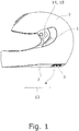
- Fig. 1
- eine schematische Seitenansicht eines ersten Ausführungsbeisplels eines vorschlagsgemäßen Schutzhelms,
- Fig. 2
- eine schematische Schnittansicht des Schutzhelms der
Fig. 1 , - Fig. 3
- eine schematische Perspektivansicht eines zweiten Ausführungsbeispiels eines vorschlagsgemäßen Schutzhelms und
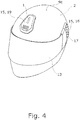
- Fig. 4
- eine schematische Perspektivansicht eines dritten Ausführungsbeispiels eines vorschlagsgemäßen Schutzhelms.
- Bei den in den
Fig. 1 bis 4 dargestellten insgesamt drei Ausführungsbeispielen von Schutzhelmen handelt es sich um Motorradschutzhelme. Sie weisen eine - jeweils unterschiedlich platzierte - Antenne 1 zur Funkübertragung, eine Außenschale 2 zur Verteilung von Aufprallkräften und eine unterhalb der Außenschale 2 - also Innen - angeordnete Innenschicht 3 zur Dämpfung von Aufprallkräften auf. Vorliegend besteht die Außenschale 2 aus Glasfaser mit einem zugesetzten Spezialharz und die Innenschicht 3 aus expandiertem Polystyrol (EPS). Nachfolgend wird jeweils zunächst das Ausführungsbeispiel derFig. 1 beschrieben und - soweit Unterschiede bestehen - auf die Ausführungsbeispiele derFig. 3 und der Flg. 4 gesondert eingegangen. - Ebenso weisen die dargestellten Schutzhelme jeweils einen Steckplatz 4 zur Kontaktierung einer Digitalvorrichtung 5 auf, bei welcher es sich um ein Bluetooth-Modul handelt, also um eine Vorrichtung zur Kommunikation in einem Bluetooth WPAN.
- Bei dem ersten -
Fig. 1 und2 - sowie bei dem dritten -Fig. 4 - Ausführungsbeispiel Ist die Antenne 1 vollständig auf der Außenseite der Außenschale 2 angeordnet, sodass die Außenschale 2 vollumfänglich die jeweilige Antenne 1 von der Innenschicht 3 trennt. Im zweiten Ausführungsbeispiel derFig. 3 hingegen Ist die Antenne 1 Innerhalb der Außenschale 2 angeordnet, sodass die Antenne 1 in allen Richtungen von der Außenschale 2 umgeben Ist. - Der Steckplatz 4 weist einen - In der
Fig. 2 schematisch dargestellten - Rahmen 6 aus Kunststoff auf, welcher formschlüssig mit einem Helmabschluss 7 des Schutzhelms verbunden ist, der seinerseits den unteren Rand der Außenschale 2 abdeckt und mit der Außenschale 2 gekoppelt ist. Auf diese Weise ist der Rahmen 6 mittelbar fest mit der Außenschale 2 verbunden. - Ebenso weist der Steckplatz 4 eine - hier nur schematisch dargestellte - Koaxialsteckvorrichtung als Kontaktvorrichtung und Übertragungsvorrichtung 8 auf. Diese Übertragungsvorrichtung 8 dient der Kontaktierung eines Antennenkontakts der aufgenommenen Digitalvorrichtung 5 und ist mit einer Übertragungsleitung 10 elektrisch verbunden, über welche die Digitalvorrichtung 5 an die Antenne 1 angeschlossen wird. Auf diese Weise kann die Digitalvorrichtung 5 die Antenne 1 für Ihre Bluetooth-Übertragung nutzen.
- Aus einer Zusammenschau der
Fig. 1 und derFig. 2 ergibt sich, dass in dem ersten Ausführungsbeispiel die Antenne 1 nicht nur seitlich, sondern sogar an einem äußeren - und speziell links äußeren - Querende des Schutzhelms angeordnet ist. Ebenso ist der Steckplatz 4 seitlich versetzt angeordnet. Die entsprechende Querrichtung 9 ist in derFig. 2 und eine Längsrichtung 12 in derFig. 1 dargestellt. Die Antenne 1 des Schutzhelms aus derFig. 4 Ist hingegen in Querrichtung 9 mittig und dafür In einer - nur in derFig. 2 dargestellten - Höhenrichtung 9a in einem Deckenbereich 9c des Schutzhelms angeordnet. Ebenso Ist in der Flg. 2 eine der obigen Längsrichtung 12 und der Höhenrichtung 9a entsprechende vertikale Mittellängsebene 9b wiedergegeben. - Die Übertragungsleltung 10 ist zwischen der Innenschicht 3 und der Außenschale 2 angeordnet und von der Übertragungsvorrichtung 8 zu einer Öffnung 11 in der Außenschale 2 geführt, durch die sie aus der Außenschale 2 heraustritt und dann die Antenne 1 kontaktiert. Der entsprechende Verlauf der Übertragungsleitung 10 sowie die Platzierung der Öffnung 11 Ist vorllegend nur für das erste Ausführungsbeispiel in der
Fig.2 gezeigt. - Die dargestellten Schutzhelme weisen je ein - nur in der Ansicht der
Fig. 1 nicht dargestelltes - Visier 13 und eine mit der Außenschale 2 befestigte Visierbefestigung 14 auf, an welcher das Visier 13 schwenkbar gelagert Ist. Ebenso ist mindestens eine Abdeckung 15 auf der Außenschale 2 angeordnet, wobei speziell das Ausführungsbeispiel derFig. 4 zwei solche Abdeckungen 15 aufweist. - In den Ausführungsbeispielen der
Fig. 1 und2 sowie 4 ist die Antenne 1 vollständig zwischen einer solchen Abdeckung 15 und der Außenschale 2 angeordnet. Aus derFig. 2 ist erkennbar, dass sich im ersten Ausführungsbeispiel auch die Öffnung 11 unter der Abdeckung 15 befindet. - Bei der - einzelnen - Abdeckung 15 des Ausführungsbelspiels der
Fig. 1 und2 sowie des Ausführungsbeispiels derFig. 3 handelt es sich um eine Aerodynamikvorrichtung 16. Diese ist angrenzend zur Visierbefestigung 14 angeordnet - an welcher sie auch befestigt ist - und glättet den ansonsten durch das Visier 13 und die Vislerbefestigung 14 bedingten, schrofferen Oberflächenverlauf Im Bereich der Visierbefestigung 14. Die Aerodynamikvorrichtung 16 weist zudem Turbulatoren 17 zum Verringern der Geräuschentwicklung auf. Die Aerodynamikvorrichtung 16 Ist an der Visierbefestigung 14 befestigt, benutzt also deren Befestigung an der Außenschale 2 mit. Entsprechend handelt es sich beim ersten Ausführungsbeispiel bei der Visierbefestigung 14 um eine an sich zu einem konturierten Oberflächenverlauf führende Struktur 18 Im oben beschriebenen Sinne. - Hiervon abweichend handelt es sich bei der Abdeckung 15 des dritten Ausführungsbeispiels der
Fig. 4 um eine verstellbare Zuführvorrichtung 19, mittels welcher Fahrtluft so umgelenkt werden kann, dass sie zwecks Kühlung durch - hier nicht dargestellte - Belüftungsöffnungen in der Außenschale 2 tritt.
Claims (15)
- Schutzhelm, insbesondere Motorradschutzhelm, mit einer Antenne (1) zur Funkübertragung, mit einer Außenschale (2) zur Verteilung von Aufprallkräften, mit einer von der Außenschale (2) aufgenommenen Innenschicht (3) zur Dämpfung von Aufprallkräften, und mit einem mit der Außenschale (2) fest verbundenem Steckplatz (4) zur Kontaktierung einer Digitalvorrichtung (5) zur drahtlosen Kommunikation, wobei der Steckplatz (4) bei Kontaktierung der Digitalvorrichtung (5) diese mit der Antenne (1) für die drahtlose Kommunikation elektrisch verbindet wobei zwischen der Antenne (1) und der Innenschicht (3) zumindest eine Teilschicht der Außenschale (2) angeordnet ist, wobei der Schutzhelm eine Übertragungsleitung (10) zur elektrischen Verbindung der Digitalvorrichtung (5) mit der Antenne (1) aufweist und wobei die Übertragungsleitung (10) zumindest teilweise innenseitig zu der Außenschale (2) geführt ist, dadurch gekennzeichnet, dass der Steckplatz (4) an einem unteren Rand des Schutzhelms angeordnet ist.
- Schutzhelm nach Anspruch 1, dadurch gekennzeichnet, dass die Antenne (1) außerhalb der Außenschale (2) angeordnet ist, vorzugsweise, dass die Antenne (1) im Wesentlichen zur Abstrahlung in einer horizontalen Senderichtung eingerichtet ist.
- Schutzhelm nach Anspruch 1 oder 2, dadurch gekennzeichnet, dass die Digitalvorrichtung (5) ein Funkmodul für ein Wireless Personal Area Network (WPAN) ist, insbesondere, dass die Digitalvorrichtung (5) ein Funkmodul für Bluetooth ist.
- Schutzhelm nach einem der Ansprüche 1 bis 3, dadurch gekennzeichnet, dass der Steckplatz (4) einen Rahmen (6) zur Aufnahme der Digitalvorrichtung (5) und eine mit der Antenne (1) elektrisch verbundene Übertragungsvorrichtung (8) zur Signalübertragung aufweist und dass bei Aufnahme der Digitalvorrichtung (5) in dem Rahmen (6) die Übertragungsvorrichtung (8) einen Antennenpol der Digitalvorrichtung (5) elektrisch konppelt.
- Schutzhelm nach einem der Ansprüche 1 bis 4, dadurch gekennzeichnet, dass die Antenne (1) eine Dipolantenne ist, vorzugsweise, dass die Übertragungsvorrichtung (8) eine Koaxialsteckvorrichtung mit mindestens zwei Kontaktpolen ist.
- Schutzhelm nach einem der Ansprüche 1 bis 5, dadurch gekennzeichnet, dass die Antenne (1) bezogen auf eine Querrichtung (9) des Schutzhelms im Wesentlichen an einem äußeren Querende des Schutzhelms angeordnet ist.
- Schutzhelm nach einem der Ansprüche 1 bis 6, dadurch gekennzeichnet, dass die Übertragungsleitung (10) vollständig innenseitig zu der Außenschale (2) geführt ist.
- Schutzhelm nach einem der Ansprüche 1 bis 7, dadurch gekennzeichnet, dass die Außenschale (2) eine Öffnung (11) aufweist und dass die Übertragungsleitung (10) für die elektrische Verbindung durch die Öffnung (11) geführt ist, vorzugsweise, dass die Übertragungsleitung (10) zumindest abschnittsweise zwischen der Außenschale (2) und der Innenschicht (3) geführt ist.
- Schutzhelm nach einem der Ansprüche 1 bis 8, dadurch gekennzeichnet, dass der Steckplatz (4) seitlich versetzt zu einer Mittelebene in Längsrichtung (11) des Schutzhelms angeordnet ist, weiter insbesondere, dass die Öffnung (10) auf derselben Seitenhälfte der Außenschale (2) wie der Steckplatz (4) angeordnet ist.
- Schutzhelm nach einem der Ansprüche 1 bis 9, dadurch gekennzeichnet, dass der Schutzhelm eine auf der Außenschale (2) angeordnete Abdeckung (15) aufweist und dass die Antenne (1) zumindest teilweise, vorzugsweise vollständig, zwischen der Außenschale (2) und der Abdeckung (15) angeordnet ist.
- Schutzhelm nach Anspruch 10, dadurch gekennzeichnet, dass der Schutzhelm ein Visier (13) zum Augenschutz und eine fest mit der Außenschale (2) verbundene Visierbefestigung (14) zur schwenkbaren Lagerung des Visiers (13) aufweist, vorzugsweise, dass die Abdeckung (15) an die Visierbefestigung (14) angrenzend angeordnet ist, insbesondere, dass die Abdeckung (15) im Wesentlichen entgegen einer Sichtrichtung des Schutzhelms zu der Visierbefestigung (14) versetzt angeordnet ist.
- Schutzhelm nach Anspruch 11, dadurch gekennzeichnet, dass die Abdeckung (15) an der Visierbefestigung (14) befestigt ist, vorzugsweise, dass die Öffnung (11) unter der Visierbefestigung (14) angeordnet ist, insbesondere, dass die Visierbefestigung (14) eine mit der Öffnung (11) fluchtende Durchbrechung zum Führen der Übertragungsleitung (10) durch die Öffnung (11) aufweist.
- Schutzhelm nach einem der Ansprüche 10 bis 12, dadurch gekennzeichnet, dass die Abdeckung (15) eine vorzugsweise einstückig ausgebildete Aerodynamikvorrichtung (16) zum Beeinflussen der Luftströmung um den Schutzhelm bei Fahrt ist, insbesondere, dass die Abdeckung (15) Turbulatoren (17) zum Erzeugen von Luftverwirbelungen bei Fahrt aufweist.
- Schutzhelm nach Anspruch 13, dadurch gekennzeichnet, dass der Schutzhelm eine an der Außenschale (2) angeordnete Struktur (18) aufweist, welche Struktur (18) gegenüber der Außenschale (2) zu einem konturierten Oberflächenverlauf des Schutzhelms führt und dass die Aerodynamikvorrichtung (16) so benachbart zu der Struktur (18) angeordnet ist, dass der durch die Aerodynamikvorrichtung (16) resultierende Oberflächenverlauf gegenüber dem konturierten Oberflächenverlauf geglättet ist.
- Schutzhelm nach Anspruch 14, dadurch gekennzeichnet, dass die Außenschale (2), vorzugsweise in einem Deckenbereich (9c) des Schutzhelms angeordnete, Belüftungsöffnungen zur Zufuhr von Fahrtluft zur Kühlung in den Schutzhelm aufweist und dass die Abdeckung (15) eine die Belüftungsöffnungen abdeckende Zuführvorrichtung (19) zum Umlenken der Fahrtluft ist, vorzugsweise, dass die Zuführvorrichtung (19) zur variablen Zufuhr von Fahrtluft verstellbar ist.
Applications Claiming Priority (2)
| Application Number | Priority Date | Filing Date | Title |
|---|---|---|---|
| DE102016115889.5A DE102016115889A1 (de) | 2016-08-26 | 2016-08-26 | Schutzhelm mit einer Antenne |
| PCT/EP2017/071259 WO2018037055A1 (de) | 2016-08-26 | 2017-08-23 | Schutzhelm mit einer antenne |
Publications (2)
| Publication Number | Publication Date |
|---|---|
| EP3503755A1 EP3503755A1 (de) | 2019-07-03 |
| EP3503755B1 true EP3503755B1 (de) | 2020-10-14 |
Family
ID=59686967
Family Applications (1)
| Application Number | Title | Priority Date | Filing Date |
|---|---|---|---|
| EP17755518.2A Active EP3503755B1 (de) | 2016-08-26 | 2017-08-23 | Schutzhelm mit einer antenne |
Country Status (6)
| Country | Link |
|---|---|
| US (1) | US12022906B2 (de) |
| EP (1) | EP3503755B1 (de) |
| CN (1) | CN109890234A (de) |
| DE (1) | DE102016115889A1 (de) |
| ES (1) | ES2857698T3 (de) |
| WO (1) | WO2018037055A1 (de) |
Families Citing this family (11)
| Publication number | Priority date | Publication date | Assignee | Title |
|---|---|---|---|---|
| DE102016115889A1 (de) | 2016-08-26 | 2018-03-01 | Schuberth Gmbh | Schutzhelm mit einer Antenne |
| DE102016115897A1 (de) | 2016-08-26 | 2018-03-01 | Schuberth Gmbh | Schutzhelm |
| DE202016008524U1 (de) | 2016-08-26 | 2018-04-03 | Schuberth Gmbh | Schutzhelm |
| DE102016122937A1 (de) * | 2016-11-28 | 2018-05-30 | Schuberth Gmbh | Außenschale für einen Schutzhelm |
| DE102017130373A1 (de) | 2017-12-15 | 2019-06-19 | Schuberth Gmbh | Schutzhelm |
| DE102018103657A1 (de) | 2018-02-19 | 2019-08-22 | Schuberth Gmbh | Schutzhelm |
| DE102018004314A1 (de) | 2018-05-30 | 2019-12-05 | Schuberth Gmbh | Schutzhelm |
| CN110693126A (zh) * | 2019-09-11 | 2020-01-17 | 浙江华消科技有限公司 | 头盔装置及其使用方法 |
| USD1005600S1 (en) * | 2021-02-17 | 2023-11-21 | Hjc Corp. | Helmet |
| USD1065695S1 (en) * | 2022-05-24 | 2025-03-04 | HJC Corporation | Helmet |
| DE102024115396A1 (de) * | 2024-06-03 | 2025-12-04 | Schuberth Gmbh | Schutzhelm mit Lautsprecheraufnahme, sowie Verfahren zur Herstellung eines solchen Schutzhelms |
Family Cites Families (167)
| Publication number | Priority date | Publication date | Assignee | Title |
|---|---|---|---|---|
| GB826012A (en) | 1955-03-29 | 1959-12-23 | American Viscose Corp | Method for moulding shaped articles |
| GB974901A (en) | 1960-11-29 | 1964-11-11 | Prec Machining Engineers Harro | Crash helmet incorporating a radio receiver |
| US3422224A (en) | 1965-04-02 | 1969-01-14 | Benton & Bowles Inc | Hat with voice amplifying system |
| US3470558A (en) | 1966-12-07 | 1969-09-30 | Bullard Co | Hat mounted radio antenna |
| US3582951A (en) | 1968-06-10 | 1971-06-01 | New Tronics Corp | Helmet antenna |
| US3885246A (en) | 1973-11-05 | 1975-05-27 | Minnesota Mining & Mfg | Retroreflective protective helmet |
| US3977003A (en) * | 1974-10-15 | 1976-08-24 | The United States Of America As Represented By The Secretary Of The Navy | Conformal helmet antenna |
| US3963917A (en) | 1975-03-07 | 1976-06-15 | Lawrence Peska Associates, Inc. | Illuminated safety helmet |
| FR2335169A1 (fr) | 1975-12-17 | 1977-07-15 | Gallet Adrien | Casque de protection et son procede de fabrication |
| US4077007A (en) * | 1976-04-05 | 1978-02-28 | The Raymond Lee Organization | Radio mounted in a helmet |
| US4109105A (en) | 1977-02-07 | 1978-08-22 | Von Statten Jr Richard J | Earphone mounting in safety helmet for motorcycle riders |
| US4130803A (en) * | 1977-05-04 | 1978-12-19 | Thompson Kenneth L | Radio equipped protective helmet |
| US4178411A (en) | 1977-07-11 | 1979-12-11 | Imperial Chemical Industries, Limited | Fibre expanded reinforced materials and their process of manufacture |
| US4152553A (en) | 1978-04-05 | 1979-05-01 | Maynard E. White | Protective helmet with voice communication system |
| US4239106A (en) | 1979-01-11 | 1980-12-16 | Gentex Corporation | Individually fitted helmet and method of and apparatus for making the same |
| FR2466174B1 (fr) | 1979-09-21 | 1985-07-26 | Gentil Alain | Casque de protection a recepteur-emetteur |
| US4321433A (en) | 1980-02-08 | 1982-03-23 | King Frederick T | Waterproof helmet encasing electronic components |
| FR2485341A1 (fr) | 1980-06-24 | 1981-12-31 | Gpa International Sarl | Casque de protection a coque injectee en thermoplastique et procede de fabrication dudit casque |
| DE3042159A1 (de) * | 1980-11-08 | 1982-06-16 | Dr.Ing.H.C. F. Porsche Ag, 7000 Stuttgart | Schutzhelm |
| US4357711A (en) * | 1981-01-29 | 1982-11-02 | Joseph Drefko | Two way radio safety helmet |
| US4400591A (en) | 1981-07-17 | 1983-08-23 | Jennings Daniel E | Simulated space helmet |
| US4563392A (en) | 1982-03-19 | 1986-01-07 | Allied Corporation | Coated extended chain polyolefin fiber |
| JPS5937324U (ja) * | 1982-09-03 | 1984-03-09 | 本田技研工業株式会社 | ヘルメツト |
| DE8226935U1 (de) | 1982-09-24 | 1983-02-24 | Krauter Vertrieb Deutschland GmbH, 7060 Schorndorf | Schutzhelm |
| US4833726A (en) * | 1986-03-07 | 1989-05-23 | Ngk Insulators, Ltd. | Helmet with two-way radio communication faculty |
| US4729132A (en) * | 1986-11-03 | 1988-03-08 | Fierro Mark F | Sports helmet |
| US4719462A (en) | 1986-11-17 | 1988-01-12 | Hawkins David E | Radar detection helmet |
| US5448780A (en) * | 1987-03-05 | 1995-09-12 | Gath; Ricky J. | Safety helmet |
| US4950439A (en) | 1987-07-10 | 1990-08-21 | C. H. Masland & Sons | Glossy finish fiber reinforced molded product |
| JPS6468507A (en) | 1987-09-08 | 1989-03-14 | Ngk Insulators Ltd | Call helmet |
| US5183701A (en) | 1987-10-02 | 1993-02-02 | Dyneema V.O.F. | Articles of highly oriented polyolefins of ultrahigh molecular weight, process for their manufacture, and their use |
| JPH01221504A (ja) | 1988-02-28 | 1989-09-05 | Honda Motor Co Ltd | ヘルメットの音響装置 |
| US4903350A (en) * | 1988-06-28 | 1990-02-27 | Giro Sport Design, Inc. | Aerodynamically streamlined bicycle racing helmet |
| ATE95675T1 (de) * | 1989-08-11 | 1993-10-15 | Andre Tisseront | Schutzhelm. |
| JPH0460927A (ja) | 1990-06-27 | 1992-02-26 | Pioneer Electron Corp | 光ピックアップ |
| US5142700A (en) * | 1990-08-27 | 1992-08-25 | Reed John W | Protective helmet containing an integral transceiver |
| FR2668901A1 (fr) | 1990-11-14 | 1992-05-15 | Entr Catalyse | Casque a emetteur-recepteur. |
| GB2254528A (en) | 1991-03-19 | 1992-10-07 | Axl Systems Ltd | Miners lamp communicator |
| US5329637A (en) | 1992-09-14 | 1994-07-19 | Walker Joseph W | Fireman's helmet with integral front and rear lights |
| US5291203A (en) | 1993-03-08 | 1994-03-01 | Schneck Eric H | Radar detection helmet |
| US5357409A (en) | 1993-03-12 | 1994-10-18 | Glatt Terry L | Illuminated safety helmet |
| US5327588A (en) | 1993-10-18 | 1994-07-12 | Louis Garneau | Safety helmet for cyclists |
| US5438702A (en) | 1993-12-28 | 1995-08-01 | Jackson; Reed B. | Bicycle helmet communication device |
| US5749096A (en) | 1994-07-01 | 1998-05-12 | Ilixco, Inc. | Helmet with high performance head and face protection utilizing complementary materials |
| US5508900A (en) | 1994-09-23 | 1996-04-16 | Norman; Charles H. | Illuminated bicycle helmet |
| US5743621A (en) | 1995-11-01 | 1998-04-28 | Mantha; Robert L. | Illuminated safety helmet |
| EP0771535B1 (de) | 1995-11-01 | 2000-02-02 | SHOEI KAKO Co., LTD. | Sicherheitshelm und Kopfschützvorrichtung dafür |
| DE29519601U1 (de) * | 1995-12-11 | 1996-02-08 | Kannenberg, Thomas, 27389 Stemmen | Schutzhelm mit integriertem Kamerasystem zur kabellosen Signalübertragung |
| US5615410A (en) | 1996-01-16 | 1997-03-25 | Demars; Robert A. | Head wear communication system |
| US5683831A (en) | 1996-03-29 | 1997-11-04 | Itt Defense, Inc. | Compact battery pack for a helmet mounted night vision device |
| US5718004A (en) | 1996-06-24 | 1998-02-17 | Troxel Cycling & Fitness Llc | Equestrian helmet |
| US5886667A (en) | 1996-10-01 | 1999-03-23 | Bondyopadhayay; Probir K. | Integrated microstrip helmet antenna system |
| US5931559A (en) | 1997-05-07 | 1999-08-03 | Pfaeffle; Patricia | Sports headgear with fiber optic lighting and strobe light |
| US6336220B1 (en) | 1997-05-29 | 2002-01-08 | Trauma-Lite Limited | Protective element |
| US6009563A (en) * | 1998-05-26 | 2000-01-04 | Swanson; David A. | Sports safety helmet |
| US6081929A (en) | 1998-12-04 | 2000-07-04 | Bell Sports, Inc. | Impact protection helmet with air extraction |
| US5996128A (en) * | 1998-12-31 | 1999-12-07 | Korea Ogk Co., Ltd. | Air flow adjusting rear member of the helmet |
| DE29906107U1 (de) | 1999-04-03 | 1999-07-08 | Stilz, Joachim, 74889 Sinsheim | Schutzhelmsystem |
| JP2000328342A (ja) | 1999-05-21 | 2000-11-28 | Tsuneo Tsukisaka | ヘルメット |
| KR200164371Y1 (ko) | 1999-07-26 | 2000-02-15 | 주식회사한국 오.지.케이 | 무선방식의핸즈프리전화통화기능을갖는헬멧의안테나구조 |
| DE29914563U1 (de) | 1999-08-11 | 2000-01-05 | Krauter, Manfred, 01900 Bretnig-Hauswalde | Schnelladaptionssystem zur lösbaren Verbindung von Zubehöreinrichtungen an Schutz- und Sicherheitshelmen |
| US6464369B1 (en) | 2000-09-28 | 2002-10-15 | Mario C. Vega | Helmet with safety light |
| CN2540799Y (zh) | 2002-04-09 | 2003-03-26 | 光阳工业股份有限公司 | 安全帽 |
| US6701537B1 (en) | 2002-06-28 | 2004-03-09 | Jamie J. Stamp | Heated visor system |
| ATE344625T1 (de) | 2002-09-02 | 2006-11-15 | Osbe Srl | Kommunikationssystem zwischen helmen und schutzhelm mit einem solchen system |
| US6691325B1 (en) | 2002-09-26 | 2004-02-17 | Bayerische Motoren Werke Ag | Helmet for a race driver |
| AU2003903305A0 (en) | 2003-06-24 | 2003-07-10 | Mark Ellis | A personal communication device |
| US20050017911A1 (en) * | 2003-07-21 | 2005-01-27 | Jen-Feng Lee | Helmet with built-in antenna |
| JP2005060889A (ja) * | 2003-08-13 | 2005-03-10 | Higashikanto:Kk | 自動二輪車用etc対応ヘルメット |
| KR100608727B1 (ko) | 2003-12-09 | 2006-08-04 | 엘지전자 주식회사 | 화상 통화용 분리형 휴대 단말기 및 그 통신 방법 |
| US20080068825A1 (en) | 2004-02-17 | 2008-03-20 | Iht Technology, Inc. | Electrical power system for crash helmets |
| US7530704B2 (en) | 2005-01-21 | 2009-05-12 | K. Harris R&D, Llc | Electrical power system for crash helmets |
| CN100526704C (zh) | 2004-06-29 | 2009-08-12 | 贝尔纳有限公司 | 蓄电池工作的反光灯以及包括反光灯和充电器的组件 |
| US20060277664A1 (en) | 2004-07-26 | 2006-12-14 | Saman Rahila Akhtar | Multifunctional helmet |
| US7261574B2 (en) | 2004-09-13 | 2007-08-28 | Hewlett-Packard Development Company, L.P. | Latch for connecting a component to a device |
| DE102004048839B4 (de) * | 2004-10-04 | 2006-07-20 | Schuberth Werk Gmbh | Integralhelm |
| CA2503167A1 (en) | 2005-04-18 | 2006-10-18 | Michael Labine | Visor device for helmet with built-in led light source |
| US8001623B2 (en) | 2005-05-26 | 2011-08-23 | Gertsch Jeffrey H | Electronic helmet |
| WO2007048145A2 (en) | 2005-10-21 | 2007-04-26 | Entrotech, Inc. | Protective sheets, articles, and methods |
| ITBS20060004A1 (it) * | 2006-01-11 | 2007-07-12 | Qfc S R L | Casco di sicurezza, specie per motociclisti, integrante un dispositivo di segnalazione luminosa |
| US8117679B2 (en) | 2006-03-22 | 2012-02-21 | Fox Head, Inc. | Molded articles and molding methods particularly for a protective helmet |
| EP1944406A1 (de) | 2007-01-10 | 2008-07-16 | Nederlandse Organisatie voor Toegepast-Natuuurwetenschappelijk Onderzoek TNO | Verfahren und Vorrichtung zur Plasmabehandlung eines langgestreckten Gegenstandes |
| US7532163B2 (en) | 2007-02-13 | 2009-05-12 | Raytheon Company | Conformal electronically scanned phased array antenna and communication system for helmets and other platforms |
| US7377666B1 (en) | 2007-04-04 | 2008-05-27 | Paul Tyler | Illuminated ear protector |
| US8661572B2 (en) | 2007-09-06 | 2014-03-04 | Artisent, Llc | Helmet edge band |
| US8009229B1 (en) * | 2007-11-07 | 2011-08-30 | Allen Peterson | Helmet safety system |
| US8853105B2 (en) | 2007-12-20 | 2014-10-07 | Honeywell International Inc. | Helmets for protection against rifle bullets |
| US20090199317A1 (en) | 2008-02-08 | 2009-08-13 | Identec Solutions Ag | Hard hat involving wireless data transmission |
| US8245326B1 (en) | 2008-02-21 | 2012-08-21 | Anthony Tolve | Helmet adjunct for retention of portable audio device |
| US7901104B2 (en) | 2008-03-11 | 2011-03-08 | Mclean Maurice A | Illuminated motorcycle helmet shell |
| EP2312960A2 (de) | 2008-05-19 | 2011-04-27 | Bae Systems Aerospace And Defense Group, INC. | Sichtverbesserungssystem |
| IT1391661B1 (it) | 2008-11-10 | 2012-01-17 | New Max Srl | Casco sportivo per motociclisti e per altri sport dotato di un dispositivo di comunicazione senza fili, particolarmente per l'uso in tecnologia bluetooth o simile. |
| CN201319192Y (zh) | 2008-11-11 | 2009-09-30 | 中兴通讯股份有限公司 | 矿用无源电子标签 |
| US8782818B2 (en) * | 2009-05-14 | 2014-07-22 | Chang-Hsien Ho | Safety helmet structure and processing method thereof |
| JP2011002958A (ja) | 2009-06-17 | 2011-01-06 | Toppan Forms Co Ltd | 構造体 |
| FR2956565B1 (fr) | 2010-02-19 | 2012-02-10 | Msa Gallet | Casque de protection |
| KR200450780Y1 (ko) | 2010-04-13 | 2010-10-29 | 이호남 | 조명수단이 구비된 안전모 |
| US8544399B2 (en) | 2010-05-20 | 2013-10-01 | Gennady Miloslavsky | Ornamented composite materials |
| US20110302701A1 (en) * | 2010-06-09 | 2011-12-15 | Kin Yung Lung Industrial Co., Ltd. | Position controlling mechanism for chin guard and visor plate of helmet |
| WO2012006653A1 (en) | 2010-07-14 | 2012-01-19 | Jeanette Jones | Improved reflective and illuminated safety helmet and safety systems comprising the same |
| US20120011631A1 (en) | 2010-07-16 | 2012-01-19 | Daniel Crossman | Headpiece assembly having removable ballistic shell and bump shell with suspension assembly |
| JP2012036527A (ja) | 2010-08-06 | 2012-02-23 | Makita Corp | ヘルメット |
| KR101076050B1 (ko) | 2010-09-29 | 2011-10-26 | 주식회사 세나테크놀로지 | 인터컴 기능을 갖는 헬멧용 블루투스 헤드셋 |
| US8600094B2 (en) | 2011-01-20 | 2013-12-03 | Cardo Systems, Inc. | Mounting panel with elongated tongue |
| US20120272435A1 (en) | 2011-04-28 | 2012-11-01 | Cardo Systems, Inc. | Helmet having embedded antenna |
| US8667617B2 (en) * | 2011-04-28 | 2014-03-11 | Cardo Systems, Inc. | Helmet having embedded antenna |
| US20130007949A1 (en) | 2011-07-08 | 2013-01-10 | Witricity Corporation | Wireless energy transfer for person worn peripherals |
| JP5814726B2 (ja) | 2011-10-03 | 2015-11-17 | 株式会社Shoei | ヘルメット |
| US8908389B2 (en) | 2011-10-07 | 2014-12-09 | Wilcox Industries Corp. | Power distribution system and helmet and method employing the same |
| DE202011051831U1 (de) | 2011-11-02 | 2011-11-16 | Matthias Reuter | Schutzhelm und aerodynamisches Stabilisierungselement |
| ITMI20120011A1 (it) * | 2012-01-05 | 2013-07-06 | Opticos Srl | Antenna a dipolo per casco di protezione |
| US9124680B2 (en) | 2012-01-19 | 2015-09-01 | Google Technology Holdings LLC | Managed material fabric for composite housing |
| ES2415739B1 (es) | 2012-01-24 | 2014-11-25 | Mat Global Solutions, S.L. | Procedimiento y aparato para la fabricación de un cuerpo de material composite provisto de una cavidad interior con una abertura al exterior |
| US11278076B2 (en) | 2012-03-06 | 2022-03-22 | Loubert S. Suddaby | Protective helmet with energy storage mechanism |
| WO2013136398A1 (ja) | 2012-03-12 | 2013-09-19 | 日本電気株式会社 | 携帯端末装置 |
| US9585433B1 (en) | 2012-05-02 | 2017-03-07 | Rawlings Sporting Goods Company, Inc. | Fiber reinforced helmet |
| US20130305437A1 (en) | 2012-05-19 | 2013-11-21 | Skully Helmets Inc. | Augmented reality motorcycle helmet |
| US9101175B2 (en) | 2012-06-28 | 2015-08-11 | Revision Military S.A.R.L. | Helmet configured for electronics |
| US10165817B2 (en) | 2012-06-28 | 2019-01-01 | Revision Military S.A.R.L. | Battery pack and helmet mounting arrangement |
| US10051908B2 (en) | 2012-06-28 | 2018-08-21 | Revision Military S.A.R.L. | Helmet-mounted display |
| US9622529B2 (en) | 2012-07-18 | 2017-04-18 | Wilcox Industries Corp. | Helmet edge trim wiring harness |
| US10492555B2 (en) | 2012-07-31 | 2019-12-03 | Rm Soldier Systems, Ltd. | Helmet mounting system |
| FR2996989B1 (fr) | 2012-10-23 | 2014-11-28 | Zedel | Casque de securite a coiffe et jugulaire perfectionnees |
| US9445639B1 (en) | 2012-11-08 | 2016-09-20 | Peter Aloumanis | Embedding intelligent electronics within a motorcyle helmet |
| US9247779B1 (en) | 2012-11-08 | 2016-02-02 | Peter Aloumanis | Enhanced global positioning system (GPS) based functionality for helmets |
| US10219571B1 (en) | 2012-11-08 | 2019-03-05 | Peter Aloumanis | In helmet sensors providing blind spot awareness |
| CN202919121U (zh) | 2012-11-22 | 2013-05-08 | 李善昌 | 消防通信头盔 |
| FR3000308B1 (fr) | 2012-12-20 | 2015-01-09 | Legrand France | Module d'appareillage electrique amovible, boite electrique d'accueil d'un tel module d'appareillage et procede de remplacement d'un tel module d'appareillage |
| US9432565B2 (en) * | 2013-01-10 | 2016-08-30 | Anthony Martin | Helmet camera system |
| US20150223547A1 (en) | 2014-02-11 | 2015-08-13 | Angel Technologies, Llc | Protective helmet with impact-absorbing layer |
| GB2518699B (en) | 2014-02-19 | 2015-08-05 | Racal Acoustics Ltd | Ballistic helmet |
| US9711146B1 (en) * | 2014-06-05 | 2017-07-18 | ProSports Technologies, LLC | Wireless system for social media management |
| CN106455742A (zh) | 2014-06-30 | 2017-02-22 | 卡多系统有限公司 | 通信系统及设备 |
| US9955049B2 (en) | 2014-07-31 | 2018-04-24 | Bell Sports, Inc. | Helmet with integrated electronics and helmet visor controls |
| US9451802B2 (en) | 2014-08-08 | 2016-09-27 | Fusar Technologies, Inc. | Helmet system and methods |
| EP3010153A1 (de) | 2014-10-13 | 2016-04-20 | Cardo International GmbH | Kommunikationssystem für einen Helm |
| US10383384B2 (en) | 2014-10-17 | 2019-08-20 | Guardhat, Inc. | Electrical connection for suspension band attachment slot of a hard hat |
| US9486027B2 (en) | 2014-10-17 | 2016-11-08 | Guardhat, Inc. | Connection assembly for adjoining a peripheral with a host wearable device |
| US9814278B2 (en) | 2014-10-17 | 2017-11-14 | Avante International Technology, Inc. | Protective headgear including a personnel electronic monitor device |
| US10160156B2 (en) | 2014-10-31 | 2018-12-25 | Board Of Trustees Of Michigan State University | Apparatus and methods for thermohydroforming |
| EP3698934B1 (de) | 2015-03-10 | 2023-06-28 | Fibre Reinforced Thermoplastics B.V. | Imprägnieranlage zur herstellung unidirektionaler faserverstärkter bänder |
| CN107636415B (zh) | 2015-04-30 | 2021-11-26 | 密执安州立大学董事会 | 复合制品及制造方法 |
| KR101530061B1 (ko) | 2015-05-04 | 2015-06-18 | (주)케이아이티 | 착용감 개선을 위한 안전진단 점검용 안전모 |
| GB2543969B (en) * | 2015-05-14 | 2017-11-15 | Peclet Ltd | Helmet with audio features |
| US9635898B2 (en) | 2015-07-07 | 2017-05-02 | Vigor Sports, Inc. | Protective helmet and music streaming system |
| CN204949670U (zh) | 2015-07-22 | 2016-01-13 | 刘长青 | 一种新型头盔 |
| DE102015216835A1 (de) | 2015-09-03 | 2017-03-09 | Bayerische Motoren Werke Aktiengesellschaft | Helmintegriertes Fahrerassistenzsystem |
| CN205106513U (zh) * | 2015-11-18 | 2016-03-30 | 蔡智敏 | 一种多功能矿工头盔 |
| US10779604B2 (en) | 2015-11-30 | 2020-09-22 | Galvion Ltd. | Earphone and helmet with earphone |
| US11633303B2 (en) | 2016-03-31 | 2023-04-25 | Husqvarna Ab | Smart earmuff and method for improved use of an earmuff |
| US9686136B1 (en) | 2016-04-13 | 2017-06-20 | Guardhat, Inc. | Assembly and method for calibrating a sensor on a wearable device |
| US11103021B2 (en) | 2016-05-25 | 2021-08-31 | Safariland, Llc | Headset with dual battery compartment |
| US20170367433A1 (en) | 2016-06-25 | 2017-12-28 | Noel Frett | WiFi Hard Helmet |
| US9968153B2 (en) | 2016-08-23 | 2018-05-15 | Bell Sports, Inc. | Helmet safety lighting system |
| DE102016115897A1 (de) | 2016-08-26 | 2018-03-01 | Schuberth Gmbh | Schutzhelm |
| DE102016115889A1 (de) | 2016-08-26 | 2018-03-01 | Schuberth Gmbh | Schutzhelm mit einer Antenne |
| DE202016008524U1 (de) | 2016-08-26 | 2018-04-03 | Schuberth Gmbh | Schutzhelm |
| CN206043574U (zh) | 2016-08-30 | 2017-03-29 | 深圳市富德康电子有限公司 | 蓝牙头盔 |
| EP3508535B1 (de) | 2016-08-31 | 2020-09-23 | Toray Industries, Inc. | Harzzusammensetzung und formartikel daraus |
| US20190269193A1 (en) | 2016-09-29 | 2019-09-05 | AnneeLondon, Inc. | Foldable Safety Helmet |
| DE102016122937A1 (de) | 2016-11-28 | 2018-05-30 | Schuberth Gmbh | Außenschale für einen Schutzhelm |
| CN206312966U (zh) | 2016-11-29 | 2017-07-07 | 常州格力博有限公司 | 电池包释放结构及其园林工具 |
| CN206560075U (zh) | 2017-03-22 | 2017-10-17 | 西南大学 | 一种智能头戴设备以及智能骑行系统 |
| US20180272928A1 (en) | 2017-03-23 | 2018-09-27 | Brad Boksteyn | Intelligent Lighted Saftey Helmet |
| US11330857B2 (en) | 2017-10-10 | 2022-05-17 | Wilcox Industries Corp. | Helmet mount interface apparatuses and methods |
| DE102017130373A1 (de) | 2017-12-15 | 2019-06-19 | Schuberth Gmbh | Schutzhelm |
| US10856599B1 (en) | 2019-03-12 | 2020-12-08 | Diego Cuenca | Hard hat with integrated electronic systems |
-
2016
- 2016-08-26 DE DE102016115889.5A patent/DE102016115889A1/de active Pending
-
2017
- 2017-08-23 EP EP17755518.2A patent/EP3503755B1/de active Active
- 2017-08-23 CN CN201780064589.3A patent/CN109890234A/zh active Pending
- 2017-08-23 US US16/328,375 patent/US12022906B2/en active Active
- 2017-08-23 WO PCT/EP2017/071259 patent/WO2018037055A1/de not_active Ceased
- 2017-08-23 ES ES17755518T patent/ES2857698T3/es active Active
Non-Patent Citations (1)
| Title |
|---|
| None * |
Also Published As
| Publication number | Publication date |
|---|---|
| EP3503755A1 (de) | 2019-07-03 |
| CN109890234A (zh) | 2019-06-14 |
| ES2857698T3 (es) | 2021-09-29 |
| US20190387829A1 (en) | 2019-12-26 |
| WO2018037055A1 (de) | 2018-03-01 |
| US12022906B2 (en) | 2024-07-02 |
| DE102016115889A1 (de) | 2018-03-01 |
| US20200383418A9 (en) | 2020-12-10 |
Similar Documents
| Publication | Publication Date | Title |
|---|---|---|
| EP3503755A1 (de) | Schutzhelm mit einer antenne | |
| EP3723531B1 (de) | Schutzhelm | |
| DE102020207197B4 (de) | Kopfband | |
| DE102007039287B4 (de) | Industrie-Stoßschutzkappe | |
| DE102012220096B4 (de) | Außengeräusche einleitender Ohrhörer | |
| DE69701959T2 (de) | Verbesserung für elektroakustisches übertragungsgerät zum einbau in einen helm und schutzhelm | |
| DE102009005302B4 (de) | Schutzhelm und Vorrichtung zur aktiven Störschallunterdrückung | |
| DE102004022937B4 (de) | Schutz- und Führungsvorrichtung für ein Kabel oder einen Schlauch mit einem metallischen Element | |
| EP2563662B1 (de) | Versorgungssystem zur versorgung von passagieren in einem passagierraum eines fahrzeugs | |
| DE3035696A1 (de) | Helm zum empfang von rundfunkuebertragungen u.dgl. | |
| DE102016115905A1 (de) | Schutzhelm | |
| DE102016210642A1 (de) | Abdeckung für einen Kupplungskopf einer Kupplungsanordnung und insbesondere einen Kupplungskopf einer Mittelpufferkupplung | |
| DE10339585A1 (de) | Optimierte Kühlluftzuführung | |
| AT500786B1 (de) | Gehörschutz- und/oder lautsprecherelement | |
| EP4418952B1 (de) | Kopfhalterung mit einem visier und einem kopfbügel | |
| DE102023101596A1 (de) | Kapuzenjacke-kapuzeneinstellsystem | |
| DE102011012247A1 (de) | Anordnung einer Stoßfängereinrichtung vor einer Kühlereinrichtung eines Kraftwagens | |
| DE202020104837U1 (de) | Helm mit Elektronikbox | |
| DE102018103657A1 (de) | Schutzhelm | |
| EP2698072B1 (de) | Schutzhelm mit Einstecktasche | |
| DE20203477U1 (de) | Sturzhelm | |
| DE60008187T2 (de) | Offener Schutzhelm mit einer Kommunikationseinrichtung | |
| EP4740773A1 (de) | Schutzhelm mit reversibel verschliessbarer aussparung zur kabeldurchführung | |
| DE10103207C1 (de) | Schutzhelm, insbesondere Integral-Sturzhelm | |
| EP3920746A1 (de) | Schutzhelm |
Legal Events
| Date | Code | Title | Description |
|---|---|---|---|
| STAA | Information on the status of an ep patent application or granted ep patent |
Free format text: STATUS: UNKNOWN |
|
| STAA | Information on the status of an ep patent application or granted ep patent |
Free format text: STATUS: THE INTERNATIONAL PUBLICATION HAS BEEN MADE |
|
| PUAI | Public reference made under article 153(3) epc to a published international application that has entered the european phase |
Free format text: ORIGINAL CODE: 0009012 |
|
| STAA | Information on the status of an ep patent application or granted ep patent |
Free format text: STATUS: REQUEST FOR EXAMINATION WAS MADE |
|
| 17P | Request for examination filed |
Effective date: 20190301 |
|
| AK | Designated contracting states |
Kind code of ref document: A1 Designated state(s): AL AT BE BG CH CY CZ DE DK EE ES FI FR GB GR HR HU IE IS IT LI LT LU LV MC MK MT NL NO PL PT RO RS SE SI SK SM TR |
|
| AX | Request for extension of the european patent |
Extension state: BA ME |
|
| DAV | Request for validation of the european patent (deleted) | ||
| DAX | Request for extension of the european patent (deleted) | ||
| GRAP | Despatch of communication of intention to grant a patent |
Free format text: ORIGINAL CODE: EPIDOSNIGR1 |
|
| STAA | Information on the status of an ep patent application or granted ep patent |
Free format text: STATUS: GRANT OF PATENT IS INTENDED |
|
| INTG | Intention to grant announced |
Effective date: 20200406 |
|
| GRAS | Grant fee paid |
Free format text: ORIGINAL CODE: EPIDOSNIGR3 |
|
| GRAJ | Information related to disapproval of communication of intention to grant by the applicant or resumption of examination proceedings by the epo deleted |
Free format text: ORIGINAL CODE: EPIDOSDIGR1 |
|
| GRAL | Information related to payment of fee for publishing/printing deleted |
Free format text: ORIGINAL CODE: EPIDOSDIGR3 |
|
| STAA | Information on the status of an ep patent application or granted ep patent |
Free format text: STATUS: REQUEST FOR EXAMINATION WAS MADE |
|
| GRAR | Information related to intention to grant a patent recorded |
Free format text: ORIGINAL CODE: EPIDOSNIGR71 |
|
| STAA | Information on the status of an ep patent application or granted ep patent |
Free format text: STATUS: GRANT OF PATENT IS INTENDED |
|
| GRAA | (expected) grant |
Free format text: ORIGINAL CODE: 0009210 |
|
| STAA | Information on the status of an ep patent application or granted ep patent |
Free format text: STATUS: THE PATENT HAS BEEN GRANTED |
|
| INTC | Intention to grant announced (deleted) | ||
| AK | Designated contracting states |
Kind code of ref document: B1 Designated state(s): AL AT BE BG CH CY CZ DE DK EE ES FI FR GB GR HR HU IE IS IT LI LT LU LV MC MK MT NL NO PL PT RO RS SE SI SK SM TR |
|
| INTG | Intention to grant announced |
Effective date: 20200904 |
|
| REG | Reference to a national code |
Ref country code: GB Ref legal event code: FG4D Free format text: NOT ENGLISH |
|
| REG | Reference to a national code |
Ref country code: AT Ref legal event code: REF Ref document number: 1322699 Country of ref document: AT Kind code of ref document: T Effective date: 20201015 Ref country code: CH Ref legal event code: EP |
|
| REG | Reference to a national code |
Ref country code: DE Ref legal event code: R096 Ref document number: 502017007771 Country of ref document: DE |
|
| REG | Reference to a national code |
Ref country code: IE Ref legal event code: FG4D Free format text: LANGUAGE OF EP DOCUMENT: GERMAN |
|
| REG | Reference to a national code |
Ref country code: NL Ref legal event code: FP |
|
| PG25 | Lapsed in a contracting state [announced via postgrant information from national office to epo] |
Ref country code: GR Free format text: LAPSE BECAUSE OF FAILURE TO SUBMIT A TRANSLATION OF THE DESCRIPTION OR TO PAY THE FEE WITHIN THE PRESCRIBED TIME-LIMIT Effective date: 20210115 Ref country code: FI Free format text: LAPSE BECAUSE OF FAILURE TO SUBMIT A TRANSLATION OF THE DESCRIPTION OR TO PAY THE FEE WITHIN THE PRESCRIBED TIME-LIMIT Effective date: 20201014 Ref country code: PT Free format text: LAPSE BECAUSE OF FAILURE TO SUBMIT A TRANSLATION OF THE DESCRIPTION OR TO PAY THE FEE WITHIN THE PRESCRIBED TIME-LIMIT Effective date: 20210215 Ref country code: RS Free format text: LAPSE BECAUSE OF FAILURE TO SUBMIT A TRANSLATION OF THE DESCRIPTION OR TO PAY THE FEE WITHIN THE PRESCRIBED TIME-LIMIT Effective date: 20201014 Ref country code: NO Free format text: LAPSE BECAUSE OF FAILURE TO SUBMIT A TRANSLATION OF THE DESCRIPTION OR TO PAY THE FEE WITHIN THE PRESCRIBED TIME-LIMIT Effective date: 20210114 |
|
| REG | Reference to a national code |
Ref country code: LT Ref legal event code: MG4D |
|
| PG25 | Lapsed in a contracting state [announced via postgrant information from national office to epo] |
Ref country code: BG Free format text: LAPSE BECAUSE OF FAILURE TO SUBMIT A TRANSLATION OF THE DESCRIPTION OR TO PAY THE FEE WITHIN THE PRESCRIBED TIME-LIMIT Effective date: 20210114 Ref country code: SE Free format text: LAPSE BECAUSE OF FAILURE TO SUBMIT A TRANSLATION OF THE DESCRIPTION OR TO PAY THE FEE WITHIN THE PRESCRIBED TIME-LIMIT Effective date: 20201014 Ref country code: IS Free format text: LAPSE BECAUSE OF FAILURE TO SUBMIT A TRANSLATION OF THE DESCRIPTION OR TO PAY THE FEE WITHIN THE PRESCRIBED TIME-LIMIT Effective date: 20210214 Ref country code: LV Free format text: LAPSE BECAUSE OF FAILURE TO SUBMIT A TRANSLATION OF THE DESCRIPTION OR TO PAY THE FEE WITHIN THE PRESCRIBED TIME-LIMIT Effective date: 20201014 Ref country code: PL Free format text: LAPSE BECAUSE OF FAILURE TO SUBMIT A TRANSLATION OF THE DESCRIPTION OR TO PAY THE FEE WITHIN THE PRESCRIBED TIME-LIMIT Effective date: 20201014 |
|
| PG25 | Lapsed in a contracting state [announced via postgrant information from national office to epo] |
Ref country code: HR Free format text: LAPSE BECAUSE OF FAILURE TO SUBMIT A TRANSLATION OF THE DESCRIPTION OR TO PAY THE FEE WITHIN THE PRESCRIBED TIME-LIMIT Effective date: 20201014 |
|
| REG | Reference to a national code |
Ref country code: DE Ref legal event code: R097 Ref document number: 502017007771 Country of ref document: DE |
|
| PG25 | Lapsed in a contracting state [announced via postgrant information from national office to epo] |
Ref country code: RO Free format text: LAPSE BECAUSE OF FAILURE TO SUBMIT A TRANSLATION OF THE DESCRIPTION OR TO PAY THE FEE WITHIN THE PRESCRIBED TIME-LIMIT Effective date: 20201014 Ref country code: SK Free format text: LAPSE BECAUSE OF FAILURE TO SUBMIT A TRANSLATION OF THE DESCRIPTION OR TO PAY THE FEE WITHIN THE PRESCRIBED TIME-LIMIT Effective date: 20201014 Ref country code: SM Free format text: LAPSE BECAUSE OF FAILURE TO SUBMIT A TRANSLATION OF THE DESCRIPTION OR TO PAY THE FEE WITHIN THE PRESCRIBED TIME-LIMIT Effective date: 20201014 Ref country code: LT Free format text: LAPSE BECAUSE OF FAILURE TO SUBMIT A TRANSLATION OF THE DESCRIPTION OR TO PAY THE FEE WITHIN THE PRESCRIBED TIME-LIMIT Effective date: 20201014 Ref country code: EE Free format text: LAPSE BECAUSE OF FAILURE TO SUBMIT A TRANSLATION OF THE DESCRIPTION OR TO PAY THE FEE WITHIN THE PRESCRIBED TIME-LIMIT Effective date: 20201014 Ref country code: CZ Free format text: LAPSE BECAUSE OF FAILURE TO SUBMIT A TRANSLATION OF THE DESCRIPTION OR TO PAY THE FEE WITHIN THE PRESCRIBED TIME-LIMIT Effective date: 20201014 |
|
| PLBE | No opposition filed within time limit |
Free format text: ORIGINAL CODE: 0009261 |
|
| STAA | Information on the status of an ep patent application or granted ep patent |
Free format text: STATUS: NO OPPOSITION FILED WITHIN TIME LIMIT |
|
| PG25 | Lapsed in a contracting state [announced via postgrant information from national office to epo] |
Ref country code: DK Free format text: LAPSE BECAUSE OF FAILURE TO SUBMIT A TRANSLATION OF THE DESCRIPTION OR TO PAY THE FEE WITHIN THE PRESCRIBED TIME-LIMIT Effective date: 20201014 |
|
| 26N | No opposition filed |
Effective date: 20210715 |
|
| REG | Reference to a national code |
Ref country code: ES Ref legal event code: FG2A Ref document number: 2857698 Country of ref document: ES Kind code of ref document: T3 Effective date: 20210929 |
|
| PG25 | Lapsed in a contracting state [announced via postgrant information from national office to epo] |
Ref country code: AL Free format text: LAPSE BECAUSE OF FAILURE TO SUBMIT A TRANSLATION OF THE DESCRIPTION OR TO PAY THE FEE WITHIN THE PRESCRIBED TIME-LIMIT Effective date: 20201014 |
|
| PG25 | Lapsed in a contracting state [announced via postgrant information from national office to epo] |
Ref country code: SI Free format text: LAPSE BECAUSE OF FAILURE TO SUBMIT A TRANSLATION OF THE DESCRIPTION OR TO PAY THE FEE WITHIN THE PRESCRIBED TIME-LIMIT Effective date: 20201014 |
|
| PG25 | Lapsed in a contracting state [announced via postgrant information from national office to epo] |
Ref country code: MC Free format text: LAPSE BECAUSE OF FAILURE TO SUBMIT A TRANSLATION OF THE DESCRIPTION OR TO PAY THE FEE WITHIN THE PRESCRIBED TIME-LIMIT Effective date: 20201014 |
|
| PG25 | Lapsed in a contracting state [announced via postgrant information from national office to epo] |
Ref country code: IS Free format text: LAPSE BECAUSE OF FAILURE TO SUBMIT A TRANSLATION OF THE DESCRIPTION OR TO PAY THE FEE WITHIN THE PRESCRIBED TIME-LIMIT Effective date: 20210214 Ref country code: LU Free format text: LAPSE BECAUSE OF NON-PAYMENT OF DUE FEES Effective date: 20210823 |
|
| PG25 | Lapsed in a contracting state [announced via postgrant information from national office to epo] |
Ref country code: IE Free format text: LAPSE BECAUSE OF NON-PAYMENT OF DUE FEES Effective date: 20210823 |
|
| PG25 | Lapsed in a contracting state [announced via postgrant information from national office to epo] |
Ref country code: CY Free format text: LAPSE BECAUSE OF FAILURE TO SUBMIT A TRANSLATION OF THE DESCRIPTION OR TO PAY THE FEE WITHIN THE PRESCRIBED TIME-LIMIT Effective date: 20201014 |
|
| P01 | Opt-out of the competence of the unified patent court (upc) registered |
Effective date: 20230606 |
|
| PG25 | Lapsed in a contracting state [announced via postgrant information from national office to epo] |
Ref country code: HU Free format text: LAPSE BECAUSE OF FAILURE TO SUBMIT A TRANSLATION OF THE DESCRIPTION OR TO PAY THE FEE WITHIN THE PRESCRIBED TIME-LIMIT; INVALID AB INITIO Effective date: 20170823 |
|
| PG25 | Lapsed in a contracting state [announced via postgrant information from national office to epo] |
Ref country code: MK Free format text: LAPSE BECAUSE OF FAILURE TO SUBMIT A TRANSLATION OF THE DESCRIPTION OR TO PAY THE FEE WITHIN THE PRESCRIBED TIME-LIMIT Effective date: 20201014 |
|
| PG25 | Lapsed in a contracting state [announced via postgrant information from national office to epo] |
Ref country code: TR Free format text: LAPSE BECAUSE OF FAILURE TO SUBMIT A TRANSLATION OF THE DESCRIPTION OR TO PAY THE FEE WITHIN THE PRESCRIBED TIME-LIMIT Effective date: 20201014 |
|
| PG25 | Lapsed in a contracting state [announced via postgrant information from national office to epo] |
Ref country code: MT Free format text: LAPSE BECAUSE OF FAILURE TO SUBMIT A TRANSLATION OF THE DESCRIPTION OR TO PAY THE FEE WITHIN THE PRESCRIBED TIME-LIMIT Effective date: 20201014 |
|
| PGFP | Annual fee paid to national office [announced via postgrant information from national office to epo] |
Ref country code: NL Payment date: 20250821 Year of fee payment: 9 |
|
| PGFP | Annual fee paid to national office [announced via postgrant information from national office to epo] |
Ref country code: ES Payment date: 20250917 Year of fee payment: 9 |
|
| PGFP | Annual fee paid to national office [announced via postgrant information from national office to epo] |
Ref country code: DE Payment date: 20250819 Year of fee payment: 9 |
|
| PGFP | Annual fee paid to national office [announced via postgrant information from national office to epo] |
Ref country code: IT Payment date: 20250829 Year of fee payment: 9 |
|
| PGFP | Annual fee paid to national office [announced via postgrant information from national office to epo] |
Ref country code: GB Payment date: 20250818 Year of fee payment: 9 Ref country code: BE Payment date: 20250820 Year of fee payment: 9 |
|
| PGFP | Annual fee paid to national office [announced via postgrant information from national office to epo] |
Ref country code: FR Payment date: 20250821 Year of fee payment: 9 Ref country code: AT Payment date: 20250819 Year of fee payment: 9 |
|
| PGFP | Annual fee paid to national office [announced via postgrant information from national office to epo] |
Ref country code: CH Payment date: 20250901 Year of fee payment: 9 |