EP3501899A1 - Dichtung für einen aussenspiegel - Google Patents
Dichtung für einen aussenspiegel Download PDFInfo
- Publication number
- EP3501899A1 EP3501899A1 EP18213476.7A EP18213476A EP3501899A1 EP 3501899 A1 EP3501899 A1 EP 3501899A1 EP 18213476 A EP18213476 A EP 18213476A EP 3501899 A1 EP3501899 A1 EP 3501899A1
- Authority
- EP
- European Patent Office
- Prior art keywords
- gasket
- external side
- side mirror
- housing bracket
- flange
- Prior art date
- Legal status (The legal status is an assumption and is not a legal conclusion. Google has not performed a legal analysis and makes no representation as to the accuracy of the status listed.)
- Granted
Links
- 241000050051 Chelone glabra Species 0.000 claims description 44
- 229920001971 elastomer Polymers 0.000 claims description 3
- 239000005060 rubber Substances 0.000 claims description 3
- 239000011800 void material Substances 0.000 claims description 3
- 230000008878 coupling Effects 0.000 claims 1
- 238000010168 coupling process Methods 0.000 claims 1
- 238000005859 coupling reaction Methods 0.000 claims 1
- 239000000463 material Substances 0.000 description 3
- 230000007613 environmental effect Effects 0.000 description 2
- 229920000049 Carbon (fiber) Polymers 0.000 description 1
- 229910000831 Steel Inorganic materials 0.000 description 1
- XAGFODPZIPBFFR-UHFFFAOYSA-N aluminium Chemical compound [Al] XAGFODPZIPBFFR-UHFFFAOYSA-N 0.000 description 1
- 229910052782 aluminium Inorganic materials 0.000 description 1
- 238000005452 bending Methods 0.000 description 1
- 239000004917 carbon fiber Substances 0.000 description 1
- 230000001010 compromised effect Effects 0.000 description 1
- 238000002955 isolation Methods 0.000 description 1
- VNWKTOKETHGBQD-UHFFFAOYSA-N methane Chemical compound C VNWKTOKETHGBQD-UHFFFAOYSA-N 0.000 description 1
- 238000012986 modification Methods 0.000 description 1
- 230000004048 modification Effects 0.000 description 1
- 238000004806 packaging method and process Methods 0.000 description 1
- 230000002093 peripheral effect Effects 0.000 description 1
- 239000004033 plastic Substances 0.000 description 1
- 239000010959 steel Substances 0.000 description 1
- 229920003051 synthetic elastomer Polymers 0.000 description 1
- 239000005061 synthetic rubber Substances 0.000 description 1
Images


Classifications
-
- B—PERFORMING OPERATIONS; TRANSPORTING
- B60—VEHICLES IN GENERAL
- B60R—VEHICLES, VEHICLE FITTINGS, OR VEHICLE PARTS, NOT OTHERWISE PROVIDED FOR
- B60R1/00—Optical viewing arrangements; Real-time viewing arrangements for drivers or passengers using optical image capturing systems, e.g. cameras or video systems specially adapted for use in or on vehicles
- B60R1/02—Rear-view mirror arrangements
- B60R1/06—Rear-view mirror arrangements mounted on vehicle exterior
- B60R1/062—Rear-view mirror arrangements mounted on vehicle exterior with remote control for adjusting position
- B60R1/07—Rear-view mirror arrangements mounted on vehicle exterior with remote control for adjusting position by electrically powered actuators
- B60R1/074—Rear-view mirror arrangements mounted on vehicle exterior with remote control for adjusting position by electrically powered actuators for retracting the mirror arrangements to a non-use position alongside the vehicle
-
- B—PERFORMING OPERATIONS; TRANSPORTING
- B60—VEHICLES IN GENERAL
- B60R—VEHICLES, VEHICLE FITTINGS, OR VEHICLE PARTS, NOT OTHERWISE PROVIDED FOR
- B60R1/00—Optical viewing arrangements; Real-time viewing arrangements for drivers or passengers using optical image capturing systems, e.g. cameras or video systems specially adapted for use in or on vehicles
- B60R1/02—Rear-view mirror arrangements
- B60R1/06—Rear-view mirror arrangements mounted on vehicle exterior
- B60R1/062—Rear-view mirror arrangements mounted on vehicle exterior with remote control for adjusting position
- B60R1/07—Rear-view mirror arrangements mounted on vehicle exterior with remote control for adjusting position by electrically powered actuators
- B60R1/072—Rear-view mirror arrangements mounted on vehicle exterior with remote control for adjusting position by electrically powered actuators for adjusting the mirror relative to its housing
-
- F—MECHANICAL ENGINEERING; LIGHTING; HEATING; WEAPONS; BLASTING
- F16—ENGINEERING ELEMENTS AND UNITS; GENERAL MEASURES FOR PRODUCING AND MAINTAINING EFFECTIVE FUNCTIONING OF MACHINES OR INSTALLATIONS; THERMAL INSULATION IN GENERAL
- F16J—PISTONS; CYLINDERS; SEALINGS
- F16J15/00—Sealings
- F16J15/02—Sealings between relatively-stationary surfaces
- F16J15/06—Sealings between relatively-stationary surfaces with solid packing compressed between sealing surfaces
- F16J15/08—Sealings between relatively-stationary surfaces with solid packing compressed between sealing surfaces with exclusively metal packing
- F16J15/0818—Flat gaskets
Definitions
- This disclosure generally relates to a gasket for an external side mirror of a vehicle.
- the gasket is mounted within the mirror such that the gasket rotates with the mirror as the mirror rotates relative to the vehicle.
- Passenger vehicles such as cars typically include sideview mirrors, also known as outside rearview mirrors or external side mirrors.
- External side mirrors are typically mounted outside the vehicle cabin to allow the driver to see the environment to the side and behind the vehicle. These mirrors can be foldable or pivotable relative to the remainder of the vehicle. The mirrors can be folded inward when, for example, the vehicle is parked so as to protect the mirrors from accidental collision or impact from other vehicles passing by.
- an external side mirror is configured to rotate relative to a connected vehicle.
- the external side mirror includes an outer cover, and a housing bracket within the outer cover.
- the housing bracket has a lower flange defining an upper surface and a lower surface.
- a gasket has a base mounted to the lower surface of the lower flange.
- the gasket includes a plurality of hooks extending upward therefrom and attached to the upper surface of the lower flange.
- the lower flange may have a perimeter with the hooks being spaced about the perimeter.
- the lower flange may define an opening sized to receive power electronic wiring, and the gasket may define an opening aligned with the opening in the lower flange.
- the gasket may be made of rubber and the hooks may be integrally-formed with the gasket.
- the gasket may include an upper surface, a lower surface, and a perimeter edge, wherein the hooks extend from the perimeter edge.
- the gasket may have a flange extending along a periphery of the lower surface.
- the outer cover may include a lower cover and a skull cap with a cutline gap between the skull cap and a base assembly of the vehicle. The gasket may seal the cutline gap.
- a gasket for an external side mirror in another embodiment, includes a base having a top surface, a bottom surface, and an edge surface about a perimeter of the gasket.
- a lip is integral with the base and extends downward from the bottom surface about the perimeter. At least a portion of the lip is located such that it is configured to seal against a base assembly of a vehicle.
- a plurality of hooks are integral with the base about the perimeter and are configured to engage a flange of a housing bracket of the external side mirror. The hooks have a first portion extending transverse from the edge surface, a second portion extending upward and transverse from the first portion, and a top portion extending inward from the second portion.
- the top portion has a lower surface configured to contact the flange of the housing bracket of the external side mirror.
- an external side mirror assembly for a vehicle includes a lower cover, and a skull cap connected to the lower cover.
- the skull cap has a lower edge configured to at least partially define a cutline gap between the skull cap and a base assembly of the vehicle.
- a housing bracket is within an interior of the connected lower cover and skull cap.
- the housing bracket has a lower surface and an upper surface.
- a gasket is removably mounted to the housing bracket.
- the gasket includes an upper surface contacting the lower surface of the housing bracket. The gasket is aligned with the cutline gap to seal the cutline gap with respect to the interior of the connected lower cover and skull cap.
- Figure 1 shows a partial view of a front driver-side of a vehicle 10 having a sideview mirror 12, also known as an external side mirror.
- the vehicle 10 is a passenger vehicle such as a car, van, truck, SUV, or the like.
- the external side mirror 12 is on the outside of the vehicle 10, and can also be referred to as an outside or external rearview mirror, a wing mirror, and other terms known in the art to refer to such a mirror.
- the external side mirror 12 has a reflective mirror 14 that can have an adjustable orientation, but typically faces the side of the vehicle to give a driver a view of the surroundings on that rearward side of the vehicle.
- Some external side mirrors in the art are adjustable relative to the vehicle.
- some external side mirrors can pivot or swivel to face inward (e.g., when the vehicle is parked) or outward.
- the external side mirror 12 is shown in use position or drive position, and the broken lines represent a parked position or folded position.
- the pivoting of the mirrors can be accomplished manually or automatic via a motor and associated structure.
- the pivoting of the mirror can be done automatically in response to the vehicle being turned off, in park, etc. This can reduce the chance of potential damage done to the mirror from things such as passing vehicles or environmental elements.
- some mirrors (including embodiments of the external side mirror described herein) have a mount or base assembly 16 that is fixed to the vehicle body and an overlying cover 18 that is pivotally connected to the base assembly 16.
- the cover 18 at least partially surrounds the reflective mirror 14 and the accompanying motor, gears, electronics, etc. that are within the external side mirror.
- a small gap may exist between the base assembly 16 and the cover 18 to allow for the pivoting of the cover 18.
- This gap may be referred to as a cutline. If left unaccounted for, wind passing over or through this cutline can cause a whistle, especially at certain high vehicle speeds. Attempts have been made to place a gasket at this cutline. However, the current gaskets have issues with assembly, and mount in an insufficient manner to properly prevent the wind noise. Furthermore, when the skull cap pivots, the gaskets are visible which is visually undesirable.
- a new cutline gasket for an external side mirror is provided.
- the gasket fits in the cutline between the base cover and the skull cap to reduce or eliminate any noise from wind passing over the cutline.
- the gasket mounts in an improved manner to provide various benefits, including an improved reduction in the noise from wind over the cutline, as well as reducing or eliminating the visibility of the gasket when the mirror is pivoted to face the vehicle.
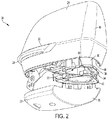
- an external side mirror 20 is shown disassembled in an exploded view (in Figure 2 ) and assembled (in Figures 3-4 ).
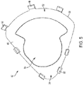
- a gasket (described below) within the external side mirror 20 is shown in isolation in Figures 5-6 .
- the external side mirror 20 includes at least some of the structure and function of the external side mirror 12 described above, with additional detail and structure described below.
- the external side mirror 20 includes a lower cover 22 (also referred to as a base cover).
- the external side mirror also includes a skull cap 24 (also referred to as an upper cover, a main cover, a top cover, or an overlying shell) connected to the lower cover 22.
- the cover 22, and skull cap 24 can collectively be referred to as a cover or outer cover.
- the skull cap 24 at least partially surrounds a reflective mirror, not shown in Figure 2 due to the orientation of the mirror.
- the skull cap 24 may include a recess or opening 26 with an associated light source 28 to provide as a turn signal.
- the lower cover 22 may include an illuminated logo, camera, puddle lamp, or other type of light known to those in the art as being part of an external side mirror.
- a housing bracket 30 is mounted within the skull cap 24 and connects to an interior portion of the skull cap 24 as will be described with reference to Figure 3 .
- the housing bracket 30 can be made of plastic (e.g., injection-molded), carbon fiber, aluminum, steel, or other like materials.
- the housing bracket 30 includes a central opening 32 to protect and guide electronic wires and mechanical connections for connection to a motor, lights, and/or other components within the external side mirror 20.
- the housing bracket 30 has a lower flange 34 that defines a lower part of the opening 32. A portion of the flange is connected to the lower cover 22, and another portion of the flange is connected to the skull cap 24, as will be further described below. This indirectly connects the skull cap 24 to the lower cover 22.
- the flange 34 has a periphery or perimeter 36 that is located within the confines of the skull cap 24. However, a large portion of the flange 34 and its perimeter 36 are located outside the confines of the lower cover 22.
- the lower cover has a curved surface 38 that curves inwardly toward the interior of the mirror, and the flange 34 rests vertically above the space outside of this curved surface 38 of the lower cover 22.
- the skull cap 24 has a curved surface 40 that curves outwardly and extends beyond the curved surface 38 of the lower cover 22 to cover the perimeter 36 of the housing bracket 30. This allows for the wires and mechanical connections (described above) to pass through the opening 32 of the housing bracket 30 and into the interior of the skull cap 24 without passing through the lower cover 22.
- a mount or base assembly 44 may also be provided that is fixed to a portion of the vehicle, such as the vehicle door.
- the base assembly 44 may extend laterally from the mirror to the vehicle, and also vertically into the opening 32 of the housing bracket 30, between the curved surface 38 of the lower cover 22 and the curved surface 40 of the skull cap 24.
- the external side mirror 20 is pivotally connected to the base assembly 44 to allow the external side mirror 20 to pivot or rotate relative to the vehicle, as described above. Also as described above, the interface between the base assembly and the external side mirror 20 may define a gap or cutline to provide clearance for the pivoting.
- a cutline gasket 42 is provided.
- the gasket 42 fills the cutline void or gap, and is trapped between the skull cap 24 and lower cover 22.
- the gasket 42 also seals this gap from external environmental conditions, such as rain, dirt, debris, etc.
- the gasket 42 since the gasket 42 is attached to the housing bracket 30 from beneath, the gasket 42 swivels with the housing bracket when the external side mirror 20 is swiveled; this prevents the gasket from being visible when the external side mirror 20 is swiveled, improving the aesthetic appearance of the mirror when the vehicle is parked, for example.
- the gasket 42 is made from a synthetic rubber material, with sufficient flexibility yet providing the proper seal at the cutline.
- the gasket 42 has a generally planar base 46, and a flange or lip 48 about its perimeter.
- the lip 48 extends slightly below a lower edge 49 of the skull cap 24, and acts as the surface that contacts the lower cover 22 and the base assembly 44 to create the seal.
- the base 46 also defines a central void or opening 50 sized similar to the opening 32 of the housing bracket 30. The opening 50 allows the electronic wires, etc. to pass therethrough, as described above.
- the gasket 42 has a first curved region 52 that matches the profile of the curved surface 38 of the lower cover 22, and an opposing second curved region 54 that matches the profile of the curved surface 40 of the skull cap 24.
- the first curved region 52 has a larger radius of curvature than that of the second curved region 54, and is interior of the second curved region 54.
- a perimeter 56 of the gasket 42 may fit and abut the interior of the flange 34 of the housing bracket 30 such that the perimeter 36 of the flange 34 of the housing bracket 30 contains the gasket 42.
- the specific shape and dimension of the gasket 42 and its opening 32 is illustrated according to one embodiment, but can be altered to fit various external side mirrors.
- the gasket 42 has a plurality of hooks or fingers 60 extending from the perimeter 56.
- the gasket 42 directly contacts the flange of the housing bracket from beneath, and the hooks 60 wrap around the perimeter edge 56 and contact the upper surface of the flange 34.
- the hooks 60 extend through openings or apertures in the flange instead of wrapping around the peripheral edge of the flange.
- the hooks 60 extend upwardly when assembled such that the hooks are configured to engage with the housing bracket 30 (e.g., the upper surface of the flange) to mount the gasket 42 to the housing bracket 30 from beneath, as seen in Figures 3-4 .
- the hooks 60 may be an integrally-formed extension of the gasket and made of the same material (e.g., rubber) as the gasket.
- the hooks 60 include a first linear portion 62 extending transversely from the outer edge surface of the gasket 42.
- a second linear portion 64 extends transversely from the first linear portion 62 and upward (e.g., when assembled).
- a tapered cap or top portion 66 extends inwardly from the second linear portion 64.
- the top portion 66 may be triangular in shape.
- a gap 67 exists between the top portion 66 and the first linear portion 62 that is sized to receive a portion of the flange 34 of the housing bracket 30.
- the top portion 66 has an underside 68 that engages with the upper surface of the flange 34 of the housing bracket 30.
- the gasket 42 is placed against the underside of the housing bracket 30 oriented such that the first curved region 52 faces the curved surface 38 and the second curved region 54 faces the curved surface 40 of the skull cap 24.
- the hooks 60 extend upwardly into the mirror assembly and hook onto a notch or cut-out 61 of the flange 34 of the housing bracket 30.
- the hooks 60 are of sufficient rigidity to hold their shape, yet flexible enough relative to the main body of the gasket 42 so that they can bend around and latch onto the upper surface of the flange 34.
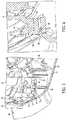
- the skull cap 24 and bottom cover 22 can be assembled to the housing bracket 30.
- the skull cap 24 has an inwardly-extending flange 70 that fits under a protrusion 72 of the housing bracket 30 to interlock the skull cap 24 to the housing bracket 30.
- Other attachments or fasteners may be used.
- the lower cover 22 includes a plurality of upwardly-extending projections or guide fingers 74 that extend through corresponding apertures 76 in the housing bracket 30. This guides the skull cap 24 onto the lower cover 22 for assembly.
- the lower cover 22 includes a plurality of attachment clips 78 that extend upwardly to flex and latch onto the housing bracket 30.
- the attachment clips 78 of the lower cover extend higher and beyond the height of the guide fingers 74.
- the lower cover 22 may also include support ribs 80 that contact the outside of the hooks 60 to inhibit the hooks 60 from bending outward and out of engagement with the housing bracket 30.
- the skull cap 24 may also include similar support ribs 82 that hold other hooks 60 of the gasket 42.
- the ribs 80 of the lower cover 22 as well as the ribs 82 of the skull cap 24 trap the hooks to ensure they maintain an engagement with the housing bracket. This allows the gasket 42 to turn with the external side mirror 20 as the external side mirror folds or pivots. Thus, the gasket does not become visible upon turning of the mirror, such as if the gasket were molded or otherwise attached to the base assembly 44. Also, the attachment of the gasket 42 via the hooks 60 being trapped by the ribs 80, 82 is less expensive than overmolding a gasket directly onto the housing bracket 30.
- the lower cover 22 and the skull cap 24 may not directly contact or engage one another.
- the gasket 42 may directly contact both the lower cover 22 and the skull cap 24 while covering the cutline gap between the base assembly 44 and the external side mirror 20.
- the gasket 42 may cover and seal a gap between the lower edge 49 of the skull cap 24 and the base assembly 44 in an area where the lower cover 22 is not directly beneath the skull cap 24, such as where the curved surface 40 of the skull cap 24 extends beyond the curved surface 38 of the lower cover 22.
- the gasket 42 can slide along the surface of the base assembly 44 while still being removably mounted to the housing bracket 30 from beneath. This provides certain benefits over other potential designs, such as where a seal is overmolded over the base assembly, because such an overmold would become visible when the mirror is rotated due to the shape of the mirror.
- Figure 7 shows an alternative embodiment of a gasket 42'.
- the gasket 42' includes the same or similar features of the gasket 42 described with reference to Figures 2-6 , except that the gasket 42' of Figure 7 includes an optional strap or hook feature 90.
- the strap 90 extends upward from two different locations at the second curved region 54. The strap 90 loops over a corner of the flange 34 of the housing bracket 30 to which the gasket 42' attaches to. This feature aids in assembly.
- an assembly operator can first wrap the hook 90 around the flange 34 to give a first attachment between the gasket 42' and the housing bracket 30, providing leverage and allowing the operator to then more easily press the hooks 60 into engagement with the housing bracket 30 to further secure the gasket 42' to the housing bracket 30 without having to hold the gasket in place from beneath while doing so.
Landscapes
- Engineering & Computer Science (AREA)
- Mechanical Engineering (AREA)
- Multimedia (AREA)
- General Engineering & Computer Science (AREA)
- Rear-View Mirror Devices That Are Mounted On The Exterior Of The Vehicle (AREA)
Applications Claiming Priority (1)
| Application Number | Priority Date | Filing Date | Title |
|---|---|---|---|
| US15/850,749 US10589683B2 (en) | 2017-12-21 | 2017-12-21 | Trapped cutline gasket for external side mirror |
Publications (2)
| Publication Number | Publication Date |
|---|---|
| EP3501899A1 true EP3501899A1 (de) | 2019-06-26 |
| EP3501899B1 EP3501899B1 (de) | 2021-06-09 |
Family
ID=64744662
Family Applications (1)
| Application Number | Title | Priority Date | Filing Date |
|---|---|---|---|
| EP18213476.7A Active EP3501899B1 (de) | 2017-12-21 | 2018-12-18 | Dichtung für einen aussenspiegel |
Country Status (3)
| Country | Link |
|---|---|
| US (1) | US10589683B2 (de) |
| EP (1) | EP3501899B1 (de) |
| CN (1) | CN109969087B (de) |
Cited By (2)
| Publication number | Priority date | Publication date | Assignee | Title |
|---|---|---|---|---|
| GB2575914A (en) * | 2018-07-02 | 2020-01-29 | Motherson Innovations Co Ltd | Base assembly and rear view device therewith |
| GB2576095A (en) * | 2018-07-02 | 2020-02-05 | Motherson Innovations Co Ltd | Sealing means, base assembly with such a sealing means and rear view device with such a base assembly |
Families Citing this family (3)
| Publication number | Priority date | Publication date | Assignee | Title |
|---|---|---|---|---|
| US11247611B2 (en) * | 2019-08-01 | 2022-02-15 | Honda Motor Co., Ltd. | Vehicle door mirror assembly |
| DE102020201511A1 (de) | 2020-02-07 | 2021-08-12 | Volkswagen Aktiengesellschaft | Außenspiegelvorrichtung |
| US11505125B2 (en) * | 2020-08-05 | 2022-11-22 | Honda Motor Co., Ltd. | Vehicle door mirror assembly |
Citations (4)
| Publication number | Priority date | Publication date | Assignee | Title |
|---|---|---|---|---|
| JPS62261557A (ja) * | 1986-05-07 | 1987-11-13 | Fuji Heavy Ind Ltd | 車両用リモ−トコントロ−ル式バツクミラ−装置 |
| WO1994011669A1 (en) * | 1992-11-16 | 1994-05-26 | Delbar Products, Incorporated | Combined adjustable outside mirror with swing lock mechanism |
| EP2399778A1 (de) * | 2010-06-28 | 2011-12-28 | SMR Patents S.à.r.l. | Spiegelfußabdeckung |
| EP2439106A1 (de) * | 2010-10-08 | 2012-04-11 | SMR Patents S.à.r.l. | Antriebsklappmechanismus |
Family Cites Families (7)
| Publication number | Priority date | Publication date | Assignee | Title |
|---|---|---|---|---|
| US6626548B2 (en) * | 2001-11-08 | 2003-09-30 | Metagal Industria E Comercio Ltda. | Rear-view mirror assembly for a motor vehicle with a mirror stabilization device |
| CN101074698A (zh) * | 2006-05-18 | 2007-11-21 | 梅卡朗两合公司 | 用于车辆反射镜的锥形支承臂接头 |
| JP5377530B2 (ja) * | 2011-01-24 | 2013-12-25 | 株式会社東海理化電機製作所 | 車両用ミラー装置 |
| JP2012192882A (ja) * | 2011-03-17 | 2012-10-11 | Murakami Corp | ドアミラーベース |
| US8882112B2 (en) * | 2012-04-30 | 2014-11-11 | Gm Global Technology Operations Llc. | Methods and apparatus for sealing automotive component pass-throughs |
| CN205417375U (zh) | 2016-02-22 | 2016-08-03 | 重庆长安汽车股份有限公司 | 一种用于后视镜密封的密封连接件及其安装结构 |
| CN107199949B (zh) * | 2017-06-13 | 2019-06-18 | 观致汽车有限公司 | 外后视镜、外后视镜壳体、外后视镜下壳体及车辆 |
-
2017
- 2017-12-21 US US15/850,749 patent/US10589683B2/en active Active
-
2018
- 2018-12-18 EP EP18213476.7A patent/EP3501899B1/de active Active
- 2018-12-20 CN CN201811563226.7A patent/CN109969087B/zh active Active
Patent Citations (4)
| Publication number | Priority date | Publication date | Assignee | Title |
|---|---|---|---|---|
| JPS62261557A (ja) * | 1986-05-07 | 1987-11-13 | Fuji Heavy Ind Ltd | 車両用リモ−トコントロ−ル式バツクミラ−装置 |
| WO1994011669A1 (en) * | 1992-11-16 | 1994-05-26 | Delbar Products, Incorporated | Combined adjustable outside mirror with swing lock mechanism |
| EP2399778A1 (de) * | 2010-06-28 | 2011-12-28 | SMR Patents S.à.r.l. | Spiegelfußabdeckung |
| EP2439106A1 (de) * | 2010-10-08 | 2012-04-11 | SMR Patents S.à.r.l. | Antriebsklappmechanismus |
Cited By (5)
| Publication number | Priority date | Publication date | Assignee | Title |
|---|---|---|---|---|
| GB2575914A (en) * | 2018-07-02 | 2020-01-29 | Motherson Innovations Co Ltd | Base assembly and rear view device therewith |
| GB2576095A (en) * | 2018-07-02 | 2020-02-05 | Motherson Innovations Co Ltd | Sealing means, base assembly with such a sealing means and rear view device with such a base assembly |
| GB2575914B (en) * | 2018-07-02 | 2020-09-23 | Motherson Innovations Co Ltd | Base assembly and rear view device therewith |
| US11479164B2 (en) | 2018-07-02 | 2022-10-25 | Motherson Innovations Company Limited | Sealing means, base assembly with such a sealing means and rear view device with such a base assembly |
| GB2576095B (en) * | 2018-07-02 | 2023-02-15 | Motherson Innovations Co Ltd | Sealing means, base assembly with such a sealing means and rear view device with such a base assembly |
Also Published As
| Publication number | Publication date |
|---|---|
| US10589683B2 (en) | 2020-03-17 |
| CN109969087B (zh) | 2021-10-26 |
| CN109969087A (zh) | 2019-07-05 |
| US20190193635A1 (en) | 2019-06-27 |
| EP3501899B1 (de) | 2021-06-09 |
Similar Documents
| Publication | Publication Date | Title |
|---|---|---|
| US10589683B2 (en) | Trapped cutline gasket for external side mirror | |
| US20110140917A1 (en) | Vehicle exterior rearview mirror system with indicator module | |
| US11535174B2 (en) | External sensor attachment portion structure | |
| EP0861750B1 (de) | Fahrzeug mit türdichtungsstrukturen | |
| US11458896B2 (en) | Vehicle door mirror | |
| JP5186866B2 (ja) | ラジエターグリルへの車載カメラ取付方法及びラジエターグリルへの車載カメラ取付構造 | |
| US8480148B1 (en) | Exterior vehicle body assembly | |
| US11951908B2 (en) | Exterior rearview mirror or winglet for a vehicle having an electrical device attached to a housing | |
| US9718408B2 (en) | Vehicle visual recognition device | |
| US20190275958A1 (en) | Structure for mounting a rear view camera on a vehicle | |
| US8414059B2 (en) | Vehicle rear windshield structure | |
| JP4101819B2 (ja) | 車両用カウルトップ構造 | |
| US7806462B2 (en) | Device for guiding a drop window | |
| CN110303984B (zh) | 车身后部构造 | |
| JP2018012383A (ja) | 車両用補機のカバー構造 | |
| US7726624B2 (en) | Mounting system for vehicular mirror | |
| US20140124643A1 (en) | Vehicle mirror device | |
| JP2019104337A (ja) | 車体上部構造 | |
| JP6341817B2 (ja) | 車両用インナーミラー構造 | |
| CN213768359U (zh) | 无人配送车 | |
| US20240092263A1 (en) | Housing for a rear view element of a rear view device for a vehicle | |
| US20230111473A1 (en) | Support for a camera display of a vehicle | |
| JP4967653B2 (ja) | ミラーの取付構造 | |
| JP6686082B2 (ja) | 外界センサ取付構造 | |
| JP2002192948A (ja) | 車両用サンバイザ |
Legal Events
| Date | Code | Title | Description |
|---|---|---|---|
| PUAI | Public reference made under article 153(3) epc to a published international application that has entered the european phase |
Free format text: ORIGINAL CODE: 0009012 |
|
| STAA | Information on the status of an ep patent application or granted ep patent |
Free format text: STATUS: THE APPLICATION HAS BEEN PUBLISHED |
|
| AK | Designated contracting states |
Kind code of ref document: A1 Designated state(s): AL AT BE BG CH CY CZ DE DK EE ES FI FR GB GR HR HU IE IS IT LI LT LU LV MC MK MT NL NO PL PT RO RS SE SI SK SM TR |
|
| AX | Request for extension of the european patent |
Extension state: BA ME |
|
| STAA | Information on the status of an ep patent application or granted ep patent |
Free format text: STATUS: REQUEST FOR EXAMINATION WAS MADE |
|
| STAA | Information on the status of an ep patent application or granted ep patent |
Free format text: STATUS: EXAMINATION IS IN PROGRESS |
|
| 17P | Request for examination filed |
Effective date: 20200102 |
|
| RBV | Designated contracting states (corrected) |
Designated state(s): AL AT BE BG CH CY CZ DE DK EE ES FI FR GB GR HR HU IE IS IT LI LT LU LV MC MK MT NL NO PL PT RO RS SE SI SK SM TR |
|
| 17Q | First examination report despatched |
Effective date: 20200124 |
|
| STAA | Information on the status of an ep patent application or granted ep patent |
Free format text: STATUS: EXAMINATION IS IN PROGRESS |
|
| GRAP | Despatch of communication of intention to grant a patent |
Free format text: ORIGINAL CODE: EPIDOSNIGR1 |
|
| STAA | Information on the status of an ep patent application or granted ep patent |
Free format text: STATUS: GRANT OF PATENT IS INTENDED |
|
| INTG | Intention to grant announced |
Effective date: 20210203 |
|
| GRAS | Grant fee paid |
Free format text: ORIGINAL CODE: EPIDOSNIGR3 |
|
| GRAA | (expected) grant |
Free format text: ORIGINAL CODE: 0009210 |
|
| STAA | Information on the status of an ep patent application or granted ep patent |
Free format text: STATUS: THE PATENT HAS BEEN GRANTED |
|
| AK | Designated contracting states |
Kind code of ref document: B1 Designated state(s): AL AT BE BG CH CY CZ DE DK EE ES FI FR GB GR HR HU IE IS IT LI LT LU LV MC MK MT NL NO PL PT RO RS SE SI SK SM TR |
|
| REG | Reference to a national code |
Ref country code: GB Ref legal event code: FG4D |
|
| REG | Reference to a national code |
Ref country code: CH Ref legal event code: EP Ref country code: AT Ref legal event code: REF Ref document number: 1400203 Country of ref document: AT Kind code of ref document: T Effective date: 20210615 |
|
| REG | Reference to a national code |
Ref country code: DE Ref legal event code: R096 Ref document number: 602018018326 Country of ref document: DE |
|
| REG | Reference to a national code |
Ref country code: IE Ref legal event code: FG4D |
|
| REG | Reference to a national code |
Ref country code: LT Ref legal event code: MG9D |
|
| PG25 | Lapsed in a contracting state [announced via postgrant information from national office to epo] |
Ref country code: BG Free format text: LAPSE BECAUSE OF FAILURE TO SUBMIT A TRANSLATION OF THE DESCRIPTION OR TO PAY THE FEE WITHIN THE PRESCRIBED TIME-LIMIT Effective date: 20210909 Ref country code: FI Free format text: LAPSE BECAUSE OF FAILURE TO SUBMIT A TRANSLATION OF THE DESCRIPTION OR TO PAY THE FEE WITHIN THE PRESCRIBED TIME-LIMIT Effective date: 20210609 Ref country code: LT Free format text: LAPSE BECAUSE OF FAILURE TO SUBMIT A TRANSLATION OF THE DESCRIPTION OR TO PAY THE FEE WITHIN THE PRESCRIBED TIME-LIMIT Effective date: 20210609 Ref country code: HR Free format text: LAPSE BECAUSE OF FAILURE TO SUBMIT A TRANSLATION OF THE DESCRIPTION OR TO PAY THE FEE WITHIN THE PRESCRIBED TIME-LIMIT Effective date: 20210609 |
|
| REG | Reference to a national code |
Ref country code: AT Ref legal event code: MK05 Ref document number: 1400203 Country of ref document: AT Kind code of ref document: T Effective date: 20210609 |
|
| REG | Reference to a national code |
Ref country code: NL Ref legal event code: MP Effective date: 20210609 |
|
| PG25 | Lapsed in a contracting state [announced via postgrant information from national office to epo] |
Ref country code: GR Free format text: LAPSE BECAUSE OF FAILURE TO SUBMIT A TRANSLATION OF THE DESCRIPTION OR TO PAY THE FEE WITHIN THE PRESCRIBED TIME-LIMIT Effective date: 20210910 Ref country code: RS Free format text: LAPSE BECAUSE OF FAILURE TO SUBMIT A TRANSLATION OF THE DESCRIPTION OR TO PAY THE FEE WITHIN THE PRESCRIBED TIME-LIMIT Effective date: 20210609 Ref country code: SE Free format text: LAPSE BECAUSE OF FAILURE TO SUBMIT A TRANSLATION OF THE DESCRIPTION OR TO PAY THE FEE WITHIN THE PRESCRIBED TIME-LIMIT Effective date: 20210609 Ref country code: LV Free format text: LAPSE BECAUSE OF FAILURE TO SUBMIT A TRANSLATION OF THE DESCRIPTION OR TO PAY THE FEE WITHIN THE PRESCRIBED TIME-LIMIT Effective date: 20210609 Ref country code: NO Free format text: LAPSE BECAUSE OF FAILURE TO SUBMIT A TRANSLATION OF THE DESCRIPTION OR TO PAY THE FEE WITHIN THE PRESCRIBED TIME-LIMIT Effective date: 20210909 |
|
| PG25 | Lapsed in a contracting state [announced via postgrant information from national office to epo] |
Ref country code: SM Free format text: LAPSE BECAUSE OF FAILURE TO SUBMIT A TRANSLATION OF THE DESCRIPTION OR TO PAY THE FEE WITHIN THE PRESCRIBED TIME-LIMIT Effective date: 20210609 Ref country code: SK Free format text: LAPSE BECAUSE OF FAILURE TO SUBMIT A TRANSLATION OF THE DESCRIPTION OR TO PAY THE FEE WITHIN THE PRESCRIBED TIME-LIMIT Effective date: 20210609 Ref country code: EE Free format text: LAPSE BECAUSE OF FAILURE TO SUBMIT A TRANSLATION OF THE DESCRIPTION OR TO PAY THE FEE WITHIN THE PRESCRIBED TIME-LIMIT Effective date: 20210609 Ref country code: ES Free format text: LAPSE BECAUSE OF FAILURE TO SUBMIT A TRANSLATION OF THE DESCRIPTION OR TO PAY THE FEE WITHIN THE PRESCRIBED TIME-LIMIT Effective date: 20210609 Ref country code: CZ Free format text: LAPSE BECAUSE OF FAILURE TO SUBMIT A TRANSLATION OF THE DESCRIPTION OR TO PAY THE FEE WITHIN THE PRESCRIBED TIME-LIMIT Effective date: 20210609 Ref country code: AT Free format text: LAPSE BECAUSE OF FAILURE TO SUBMIT A TRANSLATION OF THE DESCRIPTION OR TO PAY THE FEE WITHIN THE PRESCRIBED TIME-LIMIT Effective date: 20210609 Ref country code: RO Free format text: LAPSE BECAUSE OF FAILURE TO SUBMIT A TRANSLATION OF THE DESCRIPTION OR TO PAY THE FEE WITHIN THE PRESCRIBED TIME-LIMIT Effective date: 20210609 Ref country code: PT Free format text: LAPSE BECAUSE OF FAILURE TO SUBMIT A TRANSLATION OF THE DESCRIPTION OR TO PAY THE FEE WITHIN THE PRESCRIBED TIME-LIMIT Effective date: 20211011 Ref country code: NL Free format text: LAPSE BECAUSE OF FAILURE TO SUBMIT A TRANSLATION OF THE DESCRIPTION OR TO PAY THE FEE WITHIN THE PRESCRIBED TIME-LIMIT Effective date: 20210609 |
|
| PG25 | Lapsed in a contracting state [announced via postgrant information from national office to epo] |
Ref country code: PL Free format text: LAPSE BECAUSE OF FAILURE TO SUBMIT A TRANSLATION OF THE DESCRIPTION OR TO PAY THE FEE WITHIN THE PRESCRIBED TIME-LIMIT Effective date: 20210609 |
|
| REG | Reference to a national code |
Ref country code: DE Ref legal event code: R097 Ref document number: 602018018326 Country of ref document: DE |
|
| PLBE | No opposition filed within time limit |
Free format text: ORIGINAL CODE: 0009261 |
|
| STAA | Information on the status of an ep patent application or granted ep patent |
Free format text: STATUS: NO OPPOSITION FILED WITHIN TIME LIMIT |
|
| PG25 | Lapsed in a contracting state [announced via postgrant information from national office to epo] |
Ref country code: DK Free format text: LAPSE BECAUSE OF FAILURE TO SUBMIT A TRANSLATION OF THE DESCRIPTION OR TO PAY THE FEE WITHIN THE PRESCRIBED TIME-LIMIT Effective date: 20210609 |
|
| 26N | No opposition filed |
Effective date: 20220310 |
|
| PG25 | Lapsed in a contracting state [announced via postgrant information from national office to epo] |
Ref country code: AL Free format text: LAPSE BECAUSE OF FAILURE TO SUBMIT A TRANSLATION OF THE DESCRIPTION OR TO PAY THE FEE WITHIN THE PRESCRIBED TIME-LIMIT Effective date: 20210609 |
|
| PG25 | Lapsed in a contracting state [announced via postgrant information from national office to epo] |
Ref country code: MC Free format text: LAPSE BECAUSE OF FAILURE TO SUBMIT A TRANSLATION OF THE DESCRIPTION OR TO PAY THE FEE WITHIN THE PRESCRIBED TIME-LIMIT Effective date: 20210609 Ref country code: IT Free format text: LAPSE BECAUSE OF FAILURE TO SUBMIT A TRANSLATION OF THE DESCRIPTION OR TO PAY THE FEE WITHIN THE PRESCRIBED TIME-LIMIT Effective date: 20210609 |
|
| REG | Reference to a national code |
Ref country code: CH Ref legal event code: PL |
|
| REG | Reference to a national code |
Ref country code: BE Ref legal event code: MM Effective date: 20211231 |
|
| PG25 | Lapsed in a contracting state [announced via postgrant information from national office to epo] |
Ref country code: LU Free format text: LAPSE BECAUSE OF NON-PAYMENT OF DUE FEES Effective date: 20211218 Ref country code: IE Free format text: LAPSE BECAUSE OF NON-PAYMENT OF DUE FEES Effective date: 20211218 |
|
| PG25 | Lapsed in a contracting state [announced via postgrant information from national office to epo] |
Ref country code: FR Free format text: LAPSE BECAUSE OF NON-PAYMENT OF DUE FEES Effective date: 20211231 Ref country code: BE Free format text: LAPSE BECAUSE OF NON-PAYMENT OF DUE FEES Effective date: 20211231 |
|
| PG25 | Lapsed in a contracting state [announced via postgrant information from national office to epo] |
Ref country code: LI Free format text: LAPSE BECAUSE OF NON-PAYMENT OF DUE FEES Effective date: 20211231 Ref country code: CH Free format text: LAPSE BECAUSE OF NON-PAYMENT OF DUE FEES Effective date: 20211231 |
|
| PGFP | Annual fee paid to national office [announced via postgrant information from national office to epo] |
Ref country code: DE Payment date: 20221228 Year of fee payment: 5 |
|
| PG25 | Lapsed in a contracting state [announced via postgrant information from national office to epo] |
Ref country code: CY Free format text: LAPSE BECAUSE OF FAILURE TO SUBMIT A TRANSLATION OF THE DESCRIPTION OR TO PAY THE FEE WITHIN THE PRESCRIBED TIME-LIMIT Effective date: 20210609 |
|
| PG25 | Lapsed in a contracting state [announced via postgrant information from national office to epo] |
Ref country code: HU Free format text: LAPSE BECAUSE OF FAILURE TO SUBMIT A TRANSLATION OF THE DESCRIPTION OR TO PAY THE FEE WITHIN THE PRESCRIBED TIME-LIMIT; INVALID AB INITIO Effective date: 20181218 |
|
| GBPC | Gb: european patent ceased through non-payment of renewal fee |
Effective date: 20221218 |
|
| PG25 | Lapsed in a contracting state [announced via postgrant information from national office to epo] |
Ref country code: GB Free format text: LAPSE BECAUSE OF NON-PAYMENT OF DUE FEES Effective date: 20221218 |
|
| PG25 | Lapsed in a contracting state [announced via postgrant information from national office to epo] |
Ref country code: MK Free format text: LAPSE BECAUSE OF FAILURE TO SUBMIT A TRANSLATION OF THE DESCRIPTION OR TO PAY THE FEE WITHIN THE PRESCRIBED TIME-LIMIT Effective date: 20210609 |
|
| PGFP | Annual fee paid to national office [announced via postgrant information from national office to epo] |
Ref country code: DE Payment date: 20231229 Year of fee payment: 6 |