EP3501773A1 - Granuliervorrichtung und verfahren zur granulierung von materialsträngen - Google Patents
Granuliervorrichtung und verfahren zur granulierung von materialsträngen Download PDFInfo
- Publication number
- EP3501773A1 EP3501773A1 EP18214297.6A EP18214297A EP3501773A1 EP 3501773 A1 EP3501773 A1 EP 3501773A1 EP 18214297 A EP18214297 A EP 18214297A EP 3501773 A1 EP3501773 A1 EP 3501773A1
- Authority
- EP
- European Patent Office
- Prior art keywords
- granulating
- blade
- knife
- knife carrier
- perforated plate
- Prior art date
- Legal status (The legal status is an assumption and is not a legal conclusion. Google has not performed a legal analysis and makes no representation as to the accuracy of the status listed.)
- Granted
Links
Images


Classifications
-
- B—PERFORMING OPERATIONS; TRANSPORTING
- B29—WORKING OF PLASTICS; WORKING OF SUBSTANCES IN A PLASTIC STATE IN GENERAL
- B29B—PREPARATION OR PRETREATMENT OF THE MATERIAL TO BE SHAPED; MAKING GRANULES OR PREFORMS; RECOVERY OF PLASTICS OR OTHER CONSTITUENTS OF WASTE MATERIAL CONTAINING PLASTICS
- B29B9/00—Making granules
- B29B9/02—Making granules by dividing preformed material
- B29B9/06—Making granules by dividing preformed material in the form of filamentary material, e.g. combined with extrusion
- B29B9/065—Making granules by dividing preformed material in the form of filamentary material, e.g. combined with extrusion under-water, e.g. underwater pelletizers
-
- B—PERFORMING OPERATIONS; TRANSPORTING
- B01—PHYSICAL OR CHEMICAL PROCESSES OR APPARATUS IN GENERAL
- B01J—CHEMICAL OR PHYSICAL PROCESSES, e.g. CATALYSIS OR COLLOID CHEMISTRY; THEIR RELEVANT APPARATUS
- B01J2/00—Processes or devices for granulating materials, e.g. fertilisers in general; Rendering particulate materials free flowing in general, e.g. making them hydrophobic
- B01J2/20—Processes or devices for granulating materials, e.g. fertilisers in general; Rendering particulate materials free flowing in general, e.g. making them hydrophobic by expressing the material, e.g. through sieves and fragmenting the extruded length
-
- B—PERFORMING OPERATIONS; TRANSPORTING
- B26—HAND CUTTING TOOLS; CUTTING; SEVERING
- B26D—CUTTING; DETAILS COMMON TO MACHINES FOR PERFORATING, PUNCHING, CUTTING-OUT, STAMPING-OUT OR SEVERING
- B26D7/00—Details of apparatus for cutting, cutting-out, stamping-out, punching, perforating, or severing by means other than cutting
- B26D7/26—Means for mounting or adjusting the cutting member; Means for adjusting the stroke of the cutting member
- B26D7/2614—Means for mounting the cutting member
-
- B—PERFORMING OPERATIONS; TRANSPORTING
- B26—HAND CUTTING TOOLS; CUTTING; SEVERING
- B26D—CUTTING; DETAILS COMMON TO MACHINES FOR PERFORATING, PUNCHING, CUTTING-OUT, STAMPING-OUT OR SEVERING
- B26D1/00—Cutting through work characterised by the nature or movement of the cutting member or particular materials not otherwise provided for; Apparatus or machines therefor; Cutting members therefor
- B26D1/01—Cutting through work characterised by the nature or movement of the cutting member or particular materials not otherwise provided for; Apparatus or machines therefor; Cutting members therefor involving a cutting member which does not travel with the work
- B26D1/12—Cutting through work characterised by the nature or movement of the cutting member or particular materials not otherwise provided for; Apparatus or machines therefor; Cutting members therefor involving a cutting member which does not travel with the work having a cutting member moving about an axis
- B26D1/25—Cutting through work characterised by the nature or movement of the cutting member or particular materials not otherwise provided for; Apparatus or machines therefor; Cutting members therefor involving a cutting member which does not travel with the work having a cutting member moving about an axis with a non-circular cutting member
- B26D1/26—Cutting through work characterised by the nature or movement of the cutting member or particular materials not otherwise provided for; Apparatus or machines therefor; Cutting members therefor involving a cutting member which does not travel with the work having a cutting member moving about an axis with a non-circular cutting member moving about an axis substantially perpendicular to the line of cut
- B26D1/28—Cutting through work characterised by the nature or movement of the cutting member or particular materials not otherwise provided for; Apparatus or machines therefor; Cutting members therefor involving a cutting member which does not travel with the work having a cutting member moving about an axis with a non-circular cutting member moving about an axis substantially perpendicular to the line of cut and rotating continuously in one direction during cutting
Definitions
- the invention relates to a granulating device and a method for granulating material strands.
- a granulating device with a perforated plate and a cutter head is known.
- the cutter head has a plurality of granulating blades, which rest on a downstream side against the perforated plate and are driven in rotation by means of a drive motor, so that material strands passing through the perforated plate are cut into granules.
- the position of the pelletizer must be set exactly to the perforated plate.
- the granulator device during operation has a poor sectional image which regularly appears in the formation of so-called flags, which either adhere to the granules or detach themselves from the granules and form an undesirable fine fraction in the granules.
- the fine fraction leads on the one hand to a loss of material and on the other hand to problems in the subsequent promotion of the granules.
- the invention has for its object to provide a granulating, which ensures a simple and durable way granulation of material strands with a high quality cut.
- a granulating device with the features of claim 1.
- poor cutting quality is not only caused by the dynamic behavior of the cutter head, ie by its rotation in operation, but mainly by thermal deformation due to heating of the cutterhead when cutting.
- Known cutter heads have a cutter carrier with a plurality of cutter arms, so that a temperature gradient in the circumferential direction along the respective cutter arm and the attached granulating blade with a temperature maximum at a cutting edge of the granulating blade and a temperature minimum at a cutting edge opposite edge of the respective blade arm is formed by the cutting process.
- the temperature gradient leads during cutting to an undesirable deformation of the respective blade arm and the associated granulating blade, so that the granulating blade lifts at an outer cutting radius of a perforated plate and at the same time twisting the associated blade arm in itself. It is not possible to adjust the position of the respective granulating knife before starting the granulation in such a way that this undesirable effect is compensated during operation.
- the described thermal deformations can be considerably reduced and / or compensated if the knife carrier is or is made of a knife carrier material which at 20 ° C. has a thermal conductivity ⁇ 1 ⁇ 150 W / m / K and a thermal expansion coefficient ⁇ 1 ⁇ 16 ⁇ 10 -6 1 / K. Due to the thermal conductivity ⁇ 1 , the heat generated due to the cutting is relatively better dissipated and distributed over the knife carrier, so that a temperature gradient is substantially reduced. In conjunction with the comparatively high thermal expansion coefficient ⁇ 1 , a more uniform thermal expansion is achieved, so that disadvantageous thermal deformations are considerably reduced for the quality of the cut. In particular, due to the comparatively high coefficient of thermal expansion ⁇ 1 , the blade carrier adapts better to the comparatively hot pelletizing blades.
- the knife carrier has at least two knife arms, preferably at least three knife arms, which are arranged in particular rotationally symmetrical about the axis of rotation of the knife carrier.
- the at least two blade arms extend in a radial direction, starting from a central bearing section which permits the formation of the axis of rotation.
- the bearing portion is formed for example as a hub.
- the granulating device is particularly suitable for granulating plastic material strands which are produced from a plastic melt.
- the axis of rotation of the cutter head is arranged concentrically or eccentrically to the perforated plate.
- the drive means is preferably configured such that the cutter head at a speed of at least 1200 min -1, especially at least 1400 min -1, and especially of at least 1,600 is rotatably driven about the rotational axis min -1.
- the granulating device is designed, in particular, as a hot granulating device, in which the cut of granules takes place in a dry state.
- the knife head with the knife carrier is particularly suitable for granulating material strands from a plastic melt and / or for eccentric granulation.
- the Cutting quality can be significantly improved by means of eccentric granulation in the case of hot peeling of PVC material strands.
- the higher the thermal expansion coefficient ⁇ 1 the better the thermal expansion of the cutter head is compensated and the higher the cut quality.
- ⁇ 1 preferably: ⁇ 1 ⁇ 900 W / m / K, in particular ⁇ 1 ⁇ 700 W / m / K and in particular ⁇ 1 ⁇ 500 W / m / K.
- thermal expansion coefficient ⁇ 1 the following applies preferably: ⁇ 1 ⁇ 40 ⁇ 10 -6 1 / K, in particular ⁇ 1 ⁇ 35 ⁇ 10 -6 1 / K, and in particular ⁇ 1 ⁇ 30 ⁇ 10 -6 1 / K.
- a granulator according to claim 2 ensures a high quality cut.
- a granulator according to claim 3 ensures a high quality of cut.
- a granulating device ensures a high quality of cut at high speeds of the cutter head. Because of the low density ⁇ 1 of the cutter head is relatively light and has the critical natural frequencies which are not excited at speeds up to 1800 min -1. In addition, the center of gravity of the knife carrier shifts or the respective blade arm in operation for the built-hole plate, whereby the blade carrier or the respective blade arm deformed under the action of centrifugal force to the perforated plate. As a result, a good plan contact of each granulator on the perforated plate is achieved even at high speeds.
- the density ⁇ 1 is specified in particular for a temperature of 20 ° C. The lower the density ⁇ 1 , the higher the cut quality. For the density ⁇ 1, the following applies preferably: ⁇ 1 ⁇ 0.5 g / cm 3 , in particular ⁇ 1 ⁇ 1.0 g / cm 3 , and in particular ⁇ 1 ⁇ 1.5 g / cm 3 .
- the knife carrier material is an alloy of at least two of the materials aluminum, copper, magnesium and beryllium.
- the blade carrier material is an aluminum-copper alloy, a magnesium-aluminum alloy or a copper-beryllium alloy. The alloys may each have other alloying constituents.
- the knife carrier material is an aluminum-copper alloy.
- the alloy preferably comprises at least 85% by weight, and more preferably at least 90% by weight, of aluminum, magnesium or copper.
- a granulator according to claim 7 ensures in a simple manner a high quality cut in conjunction with a high cutting performance.
- a granulating device ensures a long-lasting high quality cut. Due to the fact that the respective granulating blade consists of a blade material with a high thermal conductivity ⁇ 2 , the respective temperature gradients and thus the thermal deformations are reduced and improved plan conditioning of the respective granulating blade on the perforated plate is achieved. In particular, due to the comparatively high thermal conductivity ⁇ 2, a slight temperature gradient is achieved with respect to the knife carrier or the respectively associated knife arm, as a result of which the face machine is improved. The higher the thermal conductivity ⁇ 2 , the lower the thermal deformations and the higher the quality of cut. For the thermal conductivity ⁇ 2 , preferably: ⁇ 2 ⁇ 200 W / m / K, in particular ⁇ 2 ⁇ 160 W / m / K, and in particular ⁇ 2 ⁇ 120 W / m / K.
- a granulator according to claim 9 ensures a long-lasting high quality cut. Due to the fact that the at least two granulating blades, in particular each granulating blade, consist of a blade material with a low coefficient of thermal expansion ⁇ 2 , thermal deformations are reduced and the plane contact of the respective granulating blade on the perforated plate is improved. In particular, due to the comparatively small coefficient of thermal expansion ⁇ 2 at high temperatures during operation, the respective granulating blade does not expand significantly more than the cutter head or the associated blade arm during operation.
- the blade material is preferably a hard metal, for example a hard metal of the grade CTS24D (ISO code K30 - K40 according to DIN ISO 513), or a ceramic material, for example based on silicon nitride or aluminum oxide.
- a granulator according to claim 10 ensures a long-lasting high quality cut.
- the density ⁇ 2 the following applies preferably: ⁇ 2 ⁇ 30 g / cm 3 , in particular ⁇ 2 ⁇ 25 g / cm 3 , and in particular ⁇ 2 ⁇ 20 g / cm 3 .
- the higher the density ⁇ 2 the more the center of gravity of the knife carrier or of the respective knife arm shifts towards the built-in perforated plate, as a result of which the knife carrier or the respective knife arm deforms under the effect of the centrifugal force to the perforated plate.
- the density ⁇ 2 is specified in particular for a temperature of 20 ° C.
- the invention is further based on the object to provide a method which allows a simple and permanent way granulation of material strands with a high quality cut.
- the advantages of the method according to the invention correspond to the already described advantages of the granulating device according to the invention.
- the molten material is preferably a plastic melt, for example a polyvinyl chloride melt (PVC melt).
- the rotary driving of the cutter head is preferably carried out at a speed of at least 1200 min -1, especially at least 1,400 min - 1, in particular of at least 1,600 min -1.
- the rotational speed is preferably at most 2,400 min -1.
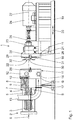
- Granulating device 1 shown in an open state is arranged downstream of an extruder 2.
- the extruder 2 has in the usual way a housing 3 with at least one housing bore 4 in which a respective treatment element shaft 5 is arranged rotatably drivable.
- the extruder 2 is used for melting and homogenizing a material to be granulated, which emerges as material melt S in a conveying direction 6 from a discharge zone 7 of the extruder 2.
- the molten material S is for example a plastic melt.
- the granulating device 1 is designed as a hot granulating device, in which the cut of granules G is dry.
- the granulator 1 has a Granulierkopfgeper 8, which is attached to the end of the housing 3.
- a Granulierkopfgeper 8 In the granulating head housing 8, at least one passage 9 is formed, through which the melted material M to be granulated is supplied to a perforated plate 10 fixed to the granulating head housing 8 at a downstream side.
- a Granulierhaube 11 is attached at the Granulierkopfgeophuse 8 .
- the first Granulierhaubenteil 12 surrounds the perforated plate 10.
- the first Granulierhaubenteil 12 opens parallel to the conveying direction 6, a supply line 13 for supplying cooling water or cooling air. From the first Granulierhaubenteil 12 discharges a discharge line 14 transversely to the conveying direction 6, so that downstream of the perforated plate 10, the cooling water or the cooling air with granules G produced from the Granulierhaube 11 can be discharged.
- the Granulierkopfgeophuse 8, the perforated plate 10 and the first Granulierhaubenteil 12 are stationary and supported by a support 17 on a foundation 18.
- the drive device 23 comprises an electric drive motor 24, a drive shaft 25 and an associated drive shaft bearing 26.
- the cutter head 22 is disposed in an interior of the Granulierhaube 11 and the perforated plate 10 facing.
- the cutter head 22 is connected in a rotationally fixed manner to the drive shaft 25 mounted in the drive shaft bearing 26 and can be driven in rotation about an axis of rotation 27 by means of the drive motor 24.
- the rotation axis 27 is arranged concentrically to the perforated plate 10.
- the cutter head 22 is used for granulating material strands, which are produced by conveying the material melt S through the perforated plate 10 by means of the extruder 2.
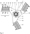
- the cutter head 22 comprises a knife carrier 29, to which a plurality of granulating blades 30, 31, 32 are fastened.
- the knife carrier 29 an end Kirende number of knife arms 33, 34, 35, which extend from a bearing portion 36 radially to the axis of rotation 27.
- Fig. 2 For example, three granulating blades 30, 31, 32 and three associated blade arms 33, 34, 35 are shown.
- the knife arms 33, 34, 35 are integrally formed with the bearing portion 36.
- the knife arms 33, 34, 35 are arranged rotationally symmetrically about the axis of rotation 27.
- the bearing portion 36 is formed as a hub and has a receiving bore 37 for receiving and rotationally fixed attachment of the drive shaft 25.
- the bearing portion 26 is thus arranged concentrically to the rotation axis 27 and rotatably connected to the drive shaft 25.
- On each of the blade arms 33, 34, 35, one of the granulator blades 30, 31, 32 is fastened to an end facing away from the bearing section 26.
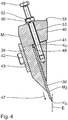
- the blade arm 33 is L-shaped in cross-section and has a support section 39 and an adjustment section 40.
- the granulator blade 30 abuts against the support portion 39 and is clamped by means of an adjusting element 41 against the support portion 39 and thus secured.
- the adjusting element 41 is for example wedge-shaped.
- the attachment of the pelletizer 30 by means of dowel screws 42 and a cover plate 43.
- the respective dowel screw 42 is guided through an associated bore 44 in the cover plate 43, extending through the support portion 39 fitting groove 45 and an associated bore 46 in the pelletizer 30 and then bolted to the adjusting element 41.
- the support section 39 and the respective fitting groove 45 extend in an adjustment direction 47, which runs obliquely to a sectional plane E.
- the cutting plane E is defined by the cutting edge K S of the granulating blade 30 extending beyond the support portion 39.
- the adjusting element 41 forms a Verstellanschlag 48, which extends along an adjustment Kv of the granulating blade 30 and abuts against it.
- adjusting screws 49, 50 are provided to adjust the pelletizer 30 .
- the adjusting screws 49 are screwed into the adjusting section 40 and bear against the adjusting element 41.
- the adjusting screws 49 are used to adjust the cutting edge Ks in the adjustment direction 47.
- the adjusting screws 49 are secured by means of a respective spring ring 51 and an associated lock nut 52.
- the adjusting screw 50 is used to adjust the cutting edge Ks against the adjustment 47.
- the adjusting screw 50 is guided through a bore 53 of the adjustment section 40 and screwed to the adjusting element 41.
- an adjusting nut 54 and a spring ring 55 are arranged on the adjusting screw 50.
- the knife carrier 29 consists of a knife carrier material M 1 .
- the knife carrier material M 1 has a thermal conductivity ⁇ 1 , a thermal expansion coefficient ⁇ 1 and a density ⁇ 1 at 20 ° C.
- thermal conductivity ⁇ 1 ⁇ 1 ⁇ 150 W / m / K, in particular ⁇ 1 ⁇ 200 W / m / K, and in particular ⁇ 1 ⁇ 250 W / m / K.
- ⁇ 1 ⁇ 7.0 g / cm 3 in particular ⁇ 1 ⁇ 5.0 g / cm 3 , and in particular ⁇ 1 ⁇ 3.0 g / cm 3 .
- the knife carrier material M 1 comprises at least one material from the group aluminum, copper, magnesium and beryllium.
- the knife carrier material M 1 is an alloy with at least two materials from this group.
- the knife carrier material M 1 is in particular an alloy with at least 80 wt .-% aluminum, magnesium or copper.
- the knife carrier material M 1 is selected, for example, from: Material standard ⁇ 1 in W / m / K at 20 ° C ⁇ 1 in 10 -6 1 / K at 20 ° C ⁇ 1 in g / cm 3 at 20 ° C AlCu4MgSi EN AW 2017 A 200 23.0 2.8 CuNi2Be EN CW 110 C 260 18 8.8
- the lower the density ⁇ 1 the more deforms or shifts the respective blade arm 33, 34, 35 under the action of centrifugal force to the perforated plate 10 and the better the planar contact with the perforated plate 10th
- the granulating blades 30, 31, 32 consist of a blade material M 2 .
- the knife material M 2 has a thermal conductivity ⁇ 2 at 20 ° C., a thermal expansion coefficient ⁇ 2 and a density ⁇ 2 .
- thermal conductivity ⁇ 2 ⁇ 2 ⁇ 15 W / m / K, in particular ⁇ 2 ⁇ 50 W / m / K, and in particular ⁇ 2 ⁇ 85 W / m / K.
- thermal expansion coefficient ⁇ 2 ⁇ 2 ⁇ 11 ⁇ 10 -6 1 / K, in particular ⁇ 2 ⁇ 9.0 ⁇ 10 -6 1 / K, and in particular ⁇ 2 ⁇ 7.0 ⁇ 10 -6 1 / K.
- ⁇ 2 For the density ⁇ 2 the following applies: ⁇ 2 ⁇ 3.0 g / cm 3 , in particular ⁇ 2 ⁇ 5.0 g / cm 3 , and in particular ⁇ 2 ⁇ 7.0 g / cm 3 .
- the knife material M 2 is selected, for example: Material standard ⁇ 2 in W / m / K at 20 ° C ⁇ 2 in 10 -6 1 / K at 20 ° C ⁇ 2 in g / cm 3 at 20 ° C CTS24D K40 DIN ISO 513 85 5.4 14.3 SNCE10 Name of Ceratizit 60 5.5 4.2 Ferro-Titanit C-Spezial Name of Thyssen-Krupp 20.5 9.2 6.5
- the operation of the granulator 1 is as follows:
- the granulating blades 30, 31, 32 are adjusted by means of the associated adjusting screws 49, 50 such that their cutting edges Ks lie in a common sectional plane E.
- the granulating blades 30, 31, 32 are displaced to the perforated plate 10 in such a way that they rest against the perforated plate 10 with the cutting edges Ks during operation of the granulating device 1.
- the material melt S is conveyed through the perforated plate 10 by means of the extruder 2.
- the cutter head 22 is rotationally driven about the axis of rotation 27 by means of the drive device 23, so that the material strands are cut into granules G by means of the granulating blades 30, 31, 32.
- the strands of material are cut dry, ie in the hot tee.
- the cutter head 22 is driven at a rotational speed n about the rotational axis 27, where: n ⁇ 1,200 min -1, in particular n ⁇ 1,400 min -1, and especially n ⁇ 1.600 min -1.
- the rotational speed n is preferably at most 2,400 min -1.
- the granules G is cooled by means of the cooling water or the cooling air and transported away through the discharge line 14.
- Fig. 5 A second embodiment of the invention described.
- the axis of rotation 27 of the cutter head 22 is arranged eccentrically to the perforated plate 10.
- the cutter head 22 and the drive device 23 are attached to the first granulating hood part 12.
- the drive motor 24 is connected via an angle gear with the drive shaft 25.
- the granulating blades 30, 31, 32 are dimensioned and arranged such that they completely cover the perforated plate 10 during a rotation of the cutter head 22.
- the second Granulierhaubenteil 21 is attached by a hinge to the first Granulierhaubenteil 12 and is closed by means of the locking device 28 fixed to the first Granulierhaubenteil 12.
- the second granulating hood part 21 On an underside, the second granulating hood part 21 has an opening, so that the cut granules G fall out of the granulating hood 11 and can be transported away.
- the further structure and the further operation will refer to the first embodiment.
Landscapes
- Engineering & Computer Science (AREA)
- Mechanical Engineering (AREA)
- Chemical & Material Sciences (AREA)
- Life Sciences & Earth Sciences (AREA)
- Forests & Forestry (AREA)
- Organic Chemistry (AREA)
- Chemical Kinetics & Catalysis (AREA)
- Processing And Handling Of Plastics And Other Materials For Molding In General (AREA)
Abstract
Description
- Die Erfindung betrifft eine Granuliervorrichtung und ein Verfahren zur Granulierung von Materialsträngen.
- Aus der
DE 103 22 610 A1 ist eine Granuliervorrichtung mit einer Lochplatte und einem Messerkopf bekannt. Der Messerkopf weist mehrere Granuliermesser auf, die an einer stromabwärtigen Seite gegen die Lochplatte anliegen und mittels eines Antriebsmotors drehangetrieben werden, sodass durch die Lochplatte tretende Materialstränge zu Granulat geschnitten werden. Zur Erzielung einer hohen Schnittqualität muss die Position der Granuliermesser zu der Lochplatte exakt eingestellt werden. Trotz einer exakten Einstellung kommt es im Betrieb der Granuliervorrichtung zu einem schlechten Schnittbild, das sich regelmäßig in der Ausbildung von sogenannten Fähnchen zeigt, die entweder am Granulat anhaften oder sich vom Granulat ablösen und einen unerwünschten Feinanteil im Granulat bilden. Der Feinanteil führt einerseits zu einem Materialverlust und andererseits zu Problemen bei der nachfolgenden Förderung des Granulats. - Der Erfindung liegt die Aufgabe zugrunde, eine Granuliervorrichtung zu schaffen, die auf einfache und dauerhafte Weise eine Granulierung von Materialsträngen mit einer hohen Schnittqualität gewährleistet.
- Diese Aufgabe wird durch eine Granuliervorrichtung mit den Merkmalen des Anspruchs 1 gelöst. Erfindungsgemäß wurde erkannt, dass eine schlechte Schnittqualität nicht nur durch das dynamische Verhalten des Messerkopfes, also durch dessen Rotation im Betrieb bedingt ist, sondern überwiegend durch thermische Verformungen aufgrund einer Erwärmung des Messerkopfes beim Schneiden. Bekannte Messerköpfe weisen einen Messerträger mit mehreren Messerarmen auf, so dass durch den Schneidvorgang ein Temperaturgradient in Umfangsrichtung entlang des jeweiligen Messerarms und des daran befestigten Granuliermessers mit einem Temperaturmaximum an einer Schneidkante des Granuliermessers und einem Temperaturminimum an einer der Schneidkante gegenüberliegenden Kante des jeweiligen Messerarms entsteht. Der Temperaturgradient führt beim Schneiden zu einer unerwünschten Verformung des jeweiligen Messerarms und des zugehörigen Granuliermessers, sodass sich das Granuliermesser an einem äußeren Schneidradius von einer Lochplatte abhebt und sich gleichzeitig der zugehörige Messerarm in sich selbst verdreht. Eine Einstellung der Position des jeweiligen Granuliermessers vor Beginn der Granulierung derart, dass dieser unerwünschte Effekt im Betrieb ausgeglichen wird, ist nicht möglich.
- Es wurde jedoch erfindungsgemäß erkannt, dass die beschriebenen thermischen Verformungen erheblich reduziert und/oder kompensiert werden können, wenn der Messerträger aus einem Messerträger-Material hergestellt ist bzw. besteht, das bei 20 °C eine Wärmeleitfähigkeit λ1 ≥ 150 W/m/K und einen Wärmeausdehnungskoeffizienten α1 ≥ 16 · 10-6 1/K hat. Durch die Wärmeleitfähigkeit λ1 wird die aufgrund des Schneidens erzeugte Wärme vergleichsweise besser abgeleitet und über den Messerträger verteilt, sodass ein Temperaturgradient wesentlich reduziert wird. In Verbindung mit dem vergleichsweise hohen Wärmeausdehnungskoeffizienten α1 wird eine gleichmäßigere Wärmeausdehnung erzielt, sodass für die Schnittqualität nachteilige thermische Verformungen erheblich reduziert werden. Insbesondere passt sich der Messerträger aufgrund des vergleichsweise hohen Wärmeausdehnungskoeffizienten α1 besser an die vergleichsweise heißeren Granuliermesser an.
- Der Messerträger weist mindestens zwei Messerarme, vorzugsweise mindestens drei Messerarme auf, die insbesondere rotationssymmetrisch um die Drehachse des Messerträgers angeordnet sind. Die mindestens zwei Messerarme erstrecken sich ausgehend von einem zentralen Lagerabschnitt, der die Ausbildung der Drehachse ermöglicht, in einer radialen Richtung. Der Lagerabschnitt ist beispielsweise als Nabe ausgebildet. Durch die mindestens zwei Messerarme und das jeweilige daran befestigte Granuliermesser werden die Materialstränge bei einer Umdrehung des Messerträgers entsprechend der Granuliermesser-Anzahl geschnitten. Hierdurch wird eine hohe Schnittleistung erzielt. Der jeweilige Messerarm und das zugehörige Granuliermesser sind beispielsweise über mehrere Schrauben miteinander verbunden. Beispielsweise ist das jeweilige Granuliermesser an dem zugehörigen Messerarm geklemmt.
- Die Granuliervorrichtung eignet sich insbesondere zur Granulierung von Kunststoff-Materialsträngen, die aus einer Kunststoffschmelze erzeugt werden. Die Drehachse des Messerkopfes ist konzentrisch oder exzentrisch zu der Lochplatte angeordnet. Die Antriebseinrichtung ist vorzugsweise derart ausgebildet, dass der Messerkopf mit einer Drehzahl von mindestens 1.200 min-1, insbesondere von mindestens 1.400 min-1, und insbesondere von mindestens 1.600 min-1 um die Drehachse drehantreibbar ist. Die Granuliervorrichtung ist insbesondere als Heißgranuliervorrichtung ausgebildet, bei der der Schnitt von Granulat trocken erfolgt.
- Der Messerkopf mit dem Messerträger eignet sich insbesondere zur Granulierung von Materialsträngen aus einer Kunststoffschmelze und/oder zur exzentrischen Granulierung. Beispielsweise ist mit dem Messerkopf die Schnittqualität bei einem Heißabschlag von PVC-Materialsträngen mittels einer exzentrischen Granulierung erheblich verbesserbar.
- Je höher die Wärmeleitfähigkeit λ1 des Messerträger-Materials ist, desto gleichmäßiger ist eine Temperaturverteilung des gesamten Messerkopfes und desto geringer sind die thermischen Verformungen. Je höher der Wärmeausdehnungskoeffizient α1 ist, desto besser wird die thermische Ausdehnung des Messerkopfes ausgeglichen und desto höher ist die Schnittqualität. Für die Wärmeleitfähigkeit λ1 gilt vorzugsweise: λ1 ≤ 900 W/m/K, insbesondere λ1 ≤ 700 W/m/K und insbesondere λ1 ≤ 500 W/m/K. Für den Wärmeausdehnungskoeffizienten α1 gilt vorzugsweise: α1 ≤ 40 · 10-6 1/K, insbesondere α1 ≤ 35 · 10-6 1/K, und insbesondere α1 ≤ 30 · 10-6 1/K.
- Eine Granuliervorrichtung nach Anspruch 2 gewährleistet eine hohe Schnittqualität. Je höher die Wärmeleitfähigkeit λ1 ist, desto geringer ist der Temperaturgradient des Messerkopfes und desto höher ist die Schnittqualität.
- Eine Granuliervorrichtung nach Anspruch 3 gewährleistet eine hohe Schnittqualität. Je höher der Wärmeausdehnungskoeffizient α1 ist, desto geringer sind die thermischen Verformungen und desto höher ist die Schnittqualität.
- Eine Granuliervorrichtung nach Anspruch 4 gewährleistet eine hohe Schnittqualität bei hohen Drehzahlen des Messerkopfes. Aufgrund der geringen Dichte ρ1 ist der Messerkopf vergleichsweise leicht und hat kritische Eigenfrequenzen, die bei Drehzahlen bis zu 1.800 min-1 nicht angeregt werden. Darüber hinaus verlagert sich der Schwerpunkt des Messerträgers bzw. des jeweiligen Messerarms im Betrieb zur eingebauten Lochplatte, wodurch sich der Messerträger bzw. der jeweilige Messerarm unter Einwirkung der Fliehkraft zu der Lochplatte verformt. Hierdurch wird auch bei hohen Drehzahlen eine gute Plananlage des jeweiligen Granuliermessers an der Lochplatte erzielt. Die Dichte ρ1 ist insbesondere für eine Temperatur von 20 °C angegeben. Je geringer die Dichte ρ1 ist, desto höher ist die Schnittqualität. Für die Dichte ρ1 gilt vorzugsweise: ρ1 ≥ 0,5 g/cm3, insbesondere ρ1 ≥ 1,0 g/cm3, und insbesondere ρ1 ≥ 1,5 g/cm3.
- Eine Granuliervorrichtung nach Anspruch 5 gewährleistet eine hohe Schnittqualität. Vorzugsweise ist das Messerträger-Material eine Legierung aus mindestens zwei der Materialien Aluminium, Kupfer, Magnesium und Beryllium. Vorzugsweise ist das Messerträger-Material eine Aluminium-Kupfer-Legierung, eine Magnesium-Aluminium-Legierung oder eine Kupfer-Beryllium-Legierung. Die Legierungen können jeweils weitere Legierungsbestandteile aufweisen.
- Eine Granuliervorrichtung nach Anspruch 6 gewährleistet in einfacher Weise eine hohe Schnittqualität. Vorzugsweise ist das Messerträger-Material eine Aluminium-Kupfer-Legierung. Beispielsweise ist das Messerträger-Material AlCu4MgSi gemäß dem Werkstoffdatenblatt EN AW-2017A (DIN EN 573-3). Die Legierung umfasst vorzugsweise mindestens 85 Gew.-%, und insbesondere mindestens 90 Gew.-% Aluminium, Magnesium oder Kupfer.
- Eine Granuliervorrichtung nach Anspruch 7 gewährleistet in einfacher Weise eine hohe Schnittqualität in Verbindung mit einer hohen Schnittleistung.
- Eine Granuliervorrichtung nach Anspruch 8 gewährleistet auf dauerhafte Weise eine hohe Schnittqualität. Dadurch, dass das jeweilige Granuliermesser aus einem Messer-Material mit einer hohen Wärmeleitfähigkeit λ2 besteht, werden die jeweiligen Temperaturgradienten und damit die thermischen Verformungen reduziert und eine verbesserte Plananlage des jeweiligen Granuliermessers an der Lochplatte erzielt. Insbesondere wird aufgrund der vergleichsweise hohen Wärmeleitfähigkeit λ2 ein geringer Temperaturgradient zum Messerträger bzw. dem jeweils zugehörigen Messerarm erzielt, wodurch die Plananlage verbessert wird. Je höher die Wärmeleitfähigkeit λ2 ist, desto geringer sind die thermischen Verformungen und desto höher ist die Schnittqualität. Für die Wärmeleitfähigkeit λ2 gilt vorzugsweise: λ2 ≤ 200 W/m/K, insbesondere λ2 ≤ 160 W/m/K, und insbesondere λ2 ≤ 120 W/m/K.
- Eine Granuliervorrichtung nach Anspruch 9 gewährleistet auf dauerhafte Weise eine hohe Schnittqualität. Dadurch, dass die mindestens zwei Granuliermesser, insbesondere jedes Granuliermesser, aus einem Messer-Material mit einem geringen Wärmeausdehnungskoeffizienten α2 bestehen, werden thermische Verformungen reduziert und die Plananlage des jeweiligen Granuliermessers an der Lochplatte verbessert. Insbesondere dehnt sich das jeweilige Granuliermesser aufgrund des vergleichsweise geringen Wärmeausdehnungskoeffizienten α2 bei hohen Temperaturen im Betrieb nicht wesentlich stärker als der Messerkopf bzw. der zugehörige Messerarm aus. Für den Wärmeausdehnungskoeffizienten α2 gilt vorzugsweise: α2 ≥ 1,0 · 10-6 1/K, insbesondere α2 ≥ 2,0 · 10-6 1/K, und insbesondere α2 ≥ 3,0 · 10-6 1/K. Das Messer-Material ist vorzugsweise ein Hartmetall, beispielsweise ein Hartmetall der Sorte CTS24D (ISO-Code K30 - K40 nach DIN ISO 513), oder ein keramisches Material, beispielsweise auf Basis von Siliziumnitrid oder Aluminiumoxid.
- Eine Granuliervorrichtung nach Anspruch 10 gewährleistet auf dauerhafte Weise eine hohe Schnittqualität. Für die Dichte ρ2 gilt vorzugsweise: ρ2 ≤ 30 g/cm3, insbesondere ρ2 ≤ 25 g/cm3, und insbesondere ρ2 ≤ 20 g/cm3. Je höher die Dichte ρ2 ist, desto mehr verlagert sich der Schwerpunkt des Messerträgers bzw. des jeweiligen Messerarms zu der eingebauten Lochplatte hin, wodurch sich der Messerträger bzw. der jeweilige Messerarm unter Einwirkung der Fliehkraft zu der Lochplatte verformt. Hierdurch wird auch bei hohen Drehzahlen eine gute Plananlage des jeweiligen Granuliermessers an der Lochplatte erzielt. Dadurch verbessert sich die Schnittqualität. Die Dichte ρ2 ist insbesondere für eine Temperatur von 20 °C angegeben.
- Der Erfindung liegt ferner die Aufgabe zugrunde, ein Verfahren zu schaffen, das auf einfache und dauerhafte Weise eine Granulierung von Materialsträngen mit einer hohen Schnittqualität ermöglicht.
- Diese Aufgabe wird durch ein Verfahren mit den Merkmalen des Anspruchs 11 gelöst. Die Vorteile des erfindungsgemäßen Verfahrens entsprechen den bereits beschriebenen Vorteilen der erfindungsgemäßen Granuliervorrichtung. Die Materialschmelze ist vorzugsweise eine Kunststoffschmelze, beispielsweise eine Polyvinylchloridschmelze (PVC-Schmelze). Das Drehantreiben des Messerkopfes erfolgt vorzugsweise mit einer Drehzahl von mindestens 1.200 min-1, insbesondere von mindestens 1.400 min- 1, und insbesondere von mindestens 1.600 min-1. Die Drehzahl beträgt vorzugsweise höchstens 2.400 min-1.
- Weitere Merkmale, Vorteile und Einzelheiten der Erfindung ergeben sich aus der nachfolgenden Beschreibung mehrerer Ausführungsbeispiele. Es zeigen:
- Fig. 1
- eine schematische Darstellung einer Granuliervorrichtung gemäß einem ersten Ausführungsbeispiel mit einer geöffneten Granulierhaube zur Veranschaulichung eines Messerkopfes mit einer zentrisch zu einer Lochplatte angeordneten Drehachse,
- Fig. 2
- eine Draufsicht auf den Messerkopf in
Fig. 1 , - Fig. 3
- eine Schnittdarstellung durch ein Granuliermesser des Messerkopfes entlang der Schnittlinie III-III in
Fig. 2 , - Fig. 4
- eine Schnittdarstellung durch das Granuliermesser des Messerkopfes entlang der Schnittlinie IV-IV in
Fig. 2 , und - Fig. 5
- eine schematische Darstellung einer Granuliervorrichtung gemäß einem zweiten Ausführungsbeispiel mit einer geöffneten Granulierhaube zur Veranschaulichung eines Messerkopfes mit einer exzentrisch zu einer Lochplatte angeordneten Drehachse.
- Nachfolgend ist anhand der
Fig. 1 bis 4 ein erstes Ausführungsbeispiel der Erfindung beschrieben. Die inFig. 1 in einem geöffneten Zustand dargestellte Granuliervorrichtung 1 ist einem Extruder 2 nachgeordnet. Der Extruder 2 weist in üblicher Weise ein Gehäuse 3 mit mindestens einer Gehäusebohrung 4 auf, in der eine jeweilige Behandlungselementwelle 5 drehantreibbar angeordnet ist. Der Extruder 2 dient zum Aufschmelzen und Homogenisieren eines zu granulierenden Materials, das als Materialschmelze S in einer Förderrichtung 6 aus einer Austragszone 7 des Extruders 2 austritt. Die Materialschmelze S ist beispielsweise eine Kunststoffschmelze. - Die Granuliervorrichtung 1 ist als Heißgranuliervorrichtung ausgebildet, bei der der Schnitt von Granulat G trocken erfolgt. Die Granuliervorrichtung 1 weist ein Granulierkopfgehäuse 8 auf, das am Ende des Gehäuses 3 befestigt ist. In dem Granulierkopfgehäuse 8 ist mindestens ein Kanal 9 ausgebildet, durch den die aufgeschmolzene und zu granulierende Materialschmelze S einer Lochplatte 10 zugeführt wird, die an einer stromabwärtigen Seite an dem Granulierkopfgehäuse 8 befestigt ist.
- An dem Granulierkopfgehäuse 8 ist ein erstes Granulierhaubenteil 12 einer Granulierhaube 11 befestigt. Das erste Granulierhaubenteil 12 umgibt die Lochplatte 10. In das erste Granulierhaubenteil 12 mündet parallel zu der Förderrichtung 6 eine Zuführleitung 13 zur Zuführung von Kühlwasser oder Kühlluft ein. Aus dem ersten Granulierhaubenteil 12 mündet eine Abführleitung 14 quer zu der Förderrichtung 6 aus, sodass stromabwärts der Lochplatte 10 das Kühlwasser bzw. die Kühlluft mit erzeugtem Granulat G aus der Granulierhaube 11 abführbar ist. Das Granulierkopfgehäuse 8, die Lochplatte 10 und das erste Granulierhaubenteil 12 sind ortsfest angeordnet und über eine Stütze 17 auf einem Fundament 18 abgestützt.
- Auf einem Grundgestell 19, das in einer Längsrichtung 20 auf dem Fundament 18 verschiebbar angeordnet ist, ist ein zweites Granulierhaubenteil 21, ein Messerkopf 22 und eine Antriebseinrichtung 23 befestigt. Die Antriebseinrichtung 23 umfasst einen elektrischen Antriebsmotor 24, eine Antriebswelle 25 und ein zugehöriges Antriebswellenlager 26. Der Messerkopf 22 ist in einem Innenraum der Granulierhaube 11 angeordnet und der Lochplatte 10 zugewandt. Der Messerkopf 22 ist mit der in dem Antriebswellenlager 26 gelagerten Antriebswelle 25 drehfest verbunden und mittels des Antriebsmotors 24 um eine Drehachse 27 drehantreibbar. Die Drehachse 27 ist konzentrisch zu der Lochplatte 10 angeordnet. Im betriebsfertigen Zustand sind die Granulierhaubenteile 12, 21 durch Verfahren des Grundgestells 19 zusammengefahren, sodass diese dicht gegeneinander anliegen. Mittels einer Verriegelungseinrichtung 28 sind die Granulierhaubenteile 12, 21 in der zusammengefahrenen Stellung miteinander dicht verbunden.
- Der Messerkopf 22 dient zur Granulierung von Materialsträngen, die dadurch erzeugt werden, dass die Materialschmelze S mittels des Extruders 2 durch die Lochplatte 10 gefördert wird. Der Messerkopf 22 umfasst einen Messerträger 29, an dem mehrere Granuliermesser 30, 31, 32 befestigt sind. Hierzu weist der Messerträger 29 eine endsprechende Anzahl an Messerarmen 33, 34, 35 auf, die sich ausgehend von einem Lagerabschnitt 36 radial zu der Drehachse 27 erstrecken. In
Fig. 2 sind beispielhaft drei Granuliermesser 30, 31, 32 und drei zugehörige Messerarme 33, 34, 35 dargestellt. Die Messerarme 33, 34, 35 sind einteilig mit dem Lagerabschnitt 36 ausgebildet. Die Messerarme 33, 34, 35 sind rotationssymmetrisch um die Drehachse 27 angeordnet. Der Lagerabschnitt 36 ist als Nabe ausgebildet und weist eine Aufnahmebohrung 37 zur Aufnahme und drehfesten Befestigung der Antriebswelle 25 auf. Der Lagerabschnitt 26 ist somit konzentrisch zu der Drehachse 27 angeordnet und drehfest mit der Antriebswelle 25 verbunden. An jedem der Messerarme 33, 34, 35 ist an einem dem Lagerabschnitt 26 abgewandten Ende eines der Granuliermesser 30, 31, 32 befestigt. - Nachfolgend ist anhand des Granuliermessers 30 und des zugehörigen Messerarms 33 die Befestigung des Granuliermessers 30 im Detail beschrieben. Die nachfolgenden Ausführungen gelten entsprechend für die Granuliermesser 31, 32 und die zugehörigen Messerarme 34, 35.
- In einem Befestigungsbereich 38 ist der Messerarm 33 im Querschnitt L-förmig ausgebildet und weist einen Auflageabschnitt 39 und einen Verstellabschnitt 40 auf. Das Granuliermesser 30 liegt gegen den Auflageabschnitt 39 an und ist mittels eines Verstellelements 41 gegen den Auflageabschnitt 39 geklemmt und somit befestigt. Das Verstellelement 41 ist beispielsweise keilförmig ausgebildet. Die Befestigung des Granuliermessers 30 erfolgt mittels Passschrauben 42 und einer Abdeckplatte 43. Die jeweilige Passschraube 42 ist durch eine zugehörige Bohrung 44 in der Abdeckplatte 43, eine sich durch den Auflageabschnitt 39 erstreckende Passnut 45 und eine zugehörige Bohrung 46 in dem Granuliermesser 30 geführt und anschließend mit dem Verstellelement 41 verschraubt. Der Auflageabschnitt 39 und die jeweilige Passnut 45 erstrecken sich in einer Verstellrichtung 47, die schräg zu einer Schnittebene E verläuft. Die Schnittebene E ist durch die Schneidkante KS des Granuliermessers 30 definiert, das sich über den Auflageabschnitt 39 hinaus erstreckt.
- Das Verstellelement 41 bildet einen Verstellanschlag 48 aus, der sich entlang einer Verstellkante Kv des Granuliermessers 30 erstreckt und gegen diese anliegt. Zum Verstellen des Granuliermessers 30 sind Verstellschrauben 49, 50 vorgesehen. Die Verstellschrauben 49 sind in den Verstellabschnitt 40 eingeschraubt und liegen gegen das Verstellelement 41 an. Die Verstellschrauben 49 dienen zur Verstellung der Schneidkante Ks in der Verstellrichtung 47. Die Verstellschrauben 49 werden mittels eines jeweiligen Federrings 51 und einer zugehörigen Sicherungsmutter 52 gesichert.
- Die Verstellschraube 50 dient zur Verstellung der Schneidkante Ks entgegen der Verstellrichtung 47. Hierzu ist die Verstellschraube 50 durch eine Bohrung 53 des Verstellabschnitts 40 geführt und mit dem Verstellelement 41 verschraubt. Zum Verstellen sind auf der Verstellschraube 50 eine Verstellmutter 54 und ein Federring 55 angeordnet.
- Der Messerträger 29 besteht aus einem Messerträger-Material M1. Das Messerträger-Material M1 hat bei 20°C eine Wärmeleitfähigkeit λ1, einen Wärmeausdehnungskoeffizient α1 und eine Dichte ρ1.
- Für die Wärmeleitfähigkeit λ1 gilt: λ1 ≥ 150 W/m/K, insbesondere λ1 ≥ 200 W/m/K, und insbesondere λ1 ≥ 250 W/m/K.
- Für den Wärmeausdehnungskoeffizienten α1 gilt: α1 ≥ 16 · 10-6 1/K, insbesondere α1 ≥ 18 · 10-6 1/K, und insbesondere α1 ≥ 21 · 10-6 1/K.
- Für die Dichte ρ1 gilt: ρ1 ≤ 7,0 g/cm3, insbesondere ρ1 ≤ 5,0 g/cm3, und insbesondere ρ1 ≤ 3,0 g/cm3.
- Das Messerträger-Material M1 umfasst mindestens ein Material aus der Gruppe Aluminium, Kupfer, Magnesium und Beryllium. Vorzugsweise ist das Messerträger-Material M1 eine Legierung mit mindestens zwei Materialien aus dieser Gruppe. Das Messerträger-Material M1 ist insbesondere eine Legierung mit mindestens 80 Gew.-% Aluminium, Magnesium oder Kupfer.
- Das Messerträger-Material M1 ist beispielsweise ausgewählt aus:
Materialbezeichnung Norm λ1 in W/m/K bei 20°C α1 in 10-6 1/K bei 20°C ρ1 in g/cm3 bei 20°C AlCu4MgSi EN AW 2017 A 200 23,0 2,8 CuNi2Be EN CW 110 C 260 18 8,8 - Je höher die Wärmeleitfähigkeit λ1 und je höher die Wärmeausdehnungskoeffizient α1 ist, desto geringer sind die thermischen Verformungen des Messerträgers 29 bzw. der Messerarme 33, 34, 35 und desto höher ist die erzielbare Schnittqualität. Je geringer die Dichte ρ1 ist, desto mehr verformt bzw. verlagert sich der jeweilige Messerarm 33, 34, 35 unter Einwirkung der Fliehkraft zu der Lochplatte 10 und desto besser ist die Plananlage an der Lochplatte 10.
- Die Granuliermesser 30, 31, 32 bestehen aus einem Messer-Material M2. Das Messer-Material M2 hat bei 20°C eine Wärmeleitfähigkeit λ2, einen Wärmeausdehnungskoeffizient α2 und eine Dichte ρ2.
- Für die Wärmeleitfähigkeit λ2 gilt: λ2 ≥ 15 W/m/K, insbesondere λ2 ≥ 50 W/m/K, und insbesondere λ2 ≥ 85 W/m/K.
- Für den Wärmeausdehnungskoeffizient α2 gilt: α2 ≤ 11 · 10-6 1/K, insbesondere α2 ≤ 9,0 · 10-6 1/K, und insbesondere α2 ≤ 7,0 · 10-6 1/K.
- Für die Dichte ρ2 gilt: ρ2 ≥ 3,0 g/cm3, insbesondere ρ2 ≥ 5,0 g/cm3, und insbesondere ρ2 ≥ 7,0 g/cm3.
- Das Messer-Material M2 ist beispielsweise ausgewählt aus:
Materialbezeichnung Norm λ2 in W/m/K bei 20°C α2 in 10-6 1/K bei 20°C ρ2 in g/cm3 bei 20°C CTS24D K40 DIN ISO 513 85 5,4 14,3 SNCE10 Bezeichnung von Ceratizit 60 5,5 4,2 Ferro-Titanit C-Spezial Bezeichnung von Thyssen-Krupp 20,5 9,2 6,5 - Die Funktionsweise der Granuliervorrichtung 1 ist wie folgt:
Die Granuliermesser 30, 31, 32 werden mittels der zugehörigen Verstellschrauben 49, 50 derart verstellt, dass deren Schneidkanten Ks in einer gemeinsamen Schnittebene E liegen. Die Granuliermesser 30, 31, 32 werden derart zu der Lochplatte 10 verlagert, dass diese im Betrieb der Granuliervorrichtung 1 mit den Schneidkanten Ks gegen die Lochplatte 10 anliegen. Zur Erzeugung der Materialstränge wird die Materialschmelze S mittels des Extruders 2 durch die Lochplatte 10 gefördert. Zeitgleich wird der Messerkopf 22 mittels der Antriebseinrichtung 23 um die Drehachse 27 drehangetrieben, sodass die Materialstränge mittels der Granuliermesser 30, 31, 32 zu Granulat G geschnitten werden. Die Materialstränge werden trocken geschnitten, also im Heißabschlag. Der Messerkopf 22 wird mit einer Drehzahl n um die Drehachse 27 angetrieben, wobei gilt: n ≥ 1.200 min-1, insbesondere n ≥ 1.400 min-1, und insbesondere n ≥ 1.600 min-1. Die Drehzahl n beträgt vorzugsweise höchstens 2.400 min-1. Das Granulat G wird mittels dem Kühlwasser oder der Kühlluft gekühlt und durch die Abführleitung 14 abtransportiert. - Durch die Kombination des Messerträger-Materials M1 und des Messer-Materials M2 werden thermische Verformungen der Messerarme 33, 34, 35 sowie der daran befestigten Granuliermesser 30, 31, 32 reduziert, sodass in einfacher und dauerhafter Weise eine exakte Plananlage der Granuliermesser 30, 31, 32 an der Lochplatte 10 und somit eine hohe Schnittqualität erzielt wird. Durch die vergleichsweise geringe Dichte ρ1 verlagern bzw. verformen sich die Messerarme 33, 34, 35 unter Einwirkung der Fliehkraft in Richtung der Lochplatte 10, sodass im Betrieb der Granuliervorrichtung 1 bei einer vergleichsweise hohen Drehzahl n die Schnittqualität hoch bleibt. Hierdurch wird eine Bildung von Fähnchen bei der Granulierung vermieden, sodass beispielsweise bei der Granulierung eine PolyvinylchloridSchmelze ein Feinanteil von ca. 0,1 Gew.-% bezogen auf das erzeugte Granulat G erzielbar ist.
- Nachfolgend ist anhand von
Fig. 5 ein zweites Ausführungsbeispiel der Erfindung beschrieben. Im Unterschied zu dem ersten Ausführungsbeispiel ist die Drehachse 27 des Messerkopfes 22 exzentrisch zu der Lochplatte 10 angeordnet. Der Messerkopf 22 und die Antriebseinrichtung 23 sind an dem ersten Granulierhaubenteil 12 befestigt. Der Antriebsmotor 24 ist über ein Winkelgetriebe mit der Antriebswelle 25 verbunden. Die Granuliermesser 30, 31, 32 sind derart dimensioniert und angeordnet, dass diese bei einer Rotation des Messerkopfes 22 die Lochplatte 10 vollständig überstreichen. Das zweite Granulierhaubenteil 21 ist mittels eines Scharniers an dem ersten Granulierhaubenteil 12 befestigt und ist mittels der Verriegelungseinrichtung 28 fest mit dem ersten Granulierhaubenteil 12 verschließbar. An einer Unterseite weist das zweite Granulierhaubenteil 21 eine Öffnung auf, sodass das geschnittene Granulat G aus der Granulierhaube 11 fallen und abtransportiert werden kann. Hinsichtlich des weiteren Aufbaus und der weiteren Funktionsweise wird auf das erste Ausführungsbeispiel verweisen.
Claims (11)
- Granuliervorrichtung zur Granulierung von Materialsträngen umfassend- eine Lochplatte (10) zur Erzeugung von Materialsträngen,- einen Messerkopf (22), der zur Erzeugung von Granulat (G) aus den Materialsträngen an einer stromabwärtigen Seite der Lochplatte (10) angeordnet ist, mit-- einem Messerträger (29) aus einem Messerträger-Material (M1), und-- mindestens einem an dem Messerträger (29) befestigten Granuliermesser (30, 31, 32), und- eine Antriebseinrichtung (23) zum Drehantreiben des Messerkopfes (22) um eine Drehachse (27), .dadurch gekennzeichnet,
dass der Messerträger (29) mindestens zwei Messerarme (33, 34, 35) zur Befestigung eines jeweiligen Granuliermessers (30, 31, 32) und einen Lagerabschnitt (36) zur drehbaren Lagerung der mindestens zwei Messerarme (33, 34, 35) umfasst,
dass das Messerträger-Material (M1) bei 20 °C eine Wärmeleitfähigkeit λ1 ≥ 150 W/m/K hat, und
dass das Messerträger-Material (M1) bei 20 °C einen Wärmeausdehnungskoeffizienten α1 ≥ 16 · 10-6 1/K hat. - Granuliervorrichtung nach Anspruch 1, dadurch gekennzeichnet, dass für die Wärmeleitfähigkeit λ1 gilt: λ1 ≥ 200 W/m/K, insbesondere λ1 ≥ 250 W/m/K.
- Granuliervorrichtung nach Anspruch 1 oder 2, dadurch gekennzeichnet, dass für den Wärmeausdehnungskoeffizienten α1 gilt: α1 ≥ 18 · 10-6 1/K, insbesondere α1 ≥ 21 · 10-6 1/K.
- Granuliervorrichtung nach einem der Ansprüche 1 bis 3, dadurch gekennzeichnet, dass das Messerträger-Material (M1) eine Dichte ρ1 hat, wobei gilt: ρ1 ≤ 7,0 g/cm3, insbesondere ρ1 ≤ 5,0 g/cm3, und insbesondere ρ1 ≤ 3,0 g/cm3.
- Granuliervorrichtung nach einem der Ansprüche 1 bis 4, dadurch gekennzeichnet, dass das Messerträger-Material (M1) mindestens ein Material aus der Gruppe Aluminium, Kupfer, Magnesium und Beryllium umfasst.
- Granuliervorrichtung nach einem der Ansprüche 1 bis 5, dadurch gekennzeichnet, dass das Messerträger-Material (M1) eine Legierung mit mindestens 80 Gew.-% Aluminium, Magnesium oder Kupfer ist.
- Granuliervorrichtung nach einem der Ansprüche 1 bis 6, dadurch gekennzeichnet, dass die mindestens zwei Messerarme (33, 34, 35) einteilig mit dem Lagerabschnitt (36) ausgebildet sind.
- Granuliervorrichtung nach einem der Ansprüche 1 bis 7, dadurch gekennzeichnet, dass das jeweilige Granuliermesser (30, 31, 32) aus einem Messer-Material (M2) hergestellt ist, das bei 20 °C eine Wärmeleitfähigkeit λ2 hat, wobei gilt: λ2 ≥ 15 W/m/K, insbesondere λ2 ≥ 50 W/m/K, und insbesondere λ2 ≥ 85 W/m/K.
- Granuliervorrichtung nach einem der Ansprüche 1 bis 8, dadurch gekennzeichnet, dass das jeweilige Granuliermesser (30, 31, 32) aus einem Messer-Material (M2) hergestellt ist, das bei 20 °C einen Wärmeausdehnungskoeffizienten α2 hat, wobei gilt: α2 ≤ 11 · 10-6 1/K, insbesondere α2 ≤ 9,0 · 10-6 1/K, und insbesondere α2 ≤ 7,0 · 10-6 1/K.
- Granuliervorrichtung nach einem der Ansprüche 1 bis 9, dadurch gekennzeichnet, dass das jeweilige Granuliermesser (30, 31, 32) aus einem Messer-Material (M2) hergestellt ist, das eine Dichte ρ2 hat, wobei gilt: ρ2 ≥ 3,0 g/cm3, insbesondere ρ2 ≥ 5,0 g/cm3, und insbesondere ρ2 ≥ 7,0 g/cm3.
- Verfahren zur Granulierung von Materialsträngen mit den Schritten:- Bereitstellen einer Granuliervorrichtung (1) nach einem der Ansprüche 1 bis 10,- Fördern einer Materialschmelze (S) durch die Lochplatte (10) derart, dass Materialstränge erzeugt werden, und- Drehantreiben des Messerkopfes (22) mittels der Antriebseinrichtung (23) derart, dass die Materialstränge mittels des mindestens einen Granuliermessers (30, 31, 32) zu Granulat (G) geschnitten werden.
Applications Claiming Priority (1)
| Application Number | Priority Date | Filing Date | Title |
|---|---|---|---|
| DE102017223708.2A DE102017223708A1 (de) | 2017-12-22 | 2017-12-22 | Messerkopf und Verfahren zur Granulierung von Materialsträngen |
Publications (2)
| Publication Number | Publication Date |
|---|---|
| EP3501773A1 true EP3501773A1 (de) | 2019-06-26 |
| EP3501773B1 EP3501773B1 (de) | 2020-10-21 |
Family
ID=64746294
Family Applications (1)
| Application Number | Title | Priority Date | Filing Date |
|---|---|---|---|
| EP18214297.6A Active EP3501773B1 (de) | 2017-12-22 | 2018-12-20 | Granuliervorrichtung und verfahren zur granulierung von materialsträngen |
Country Status (2)
| Country | Link |
|---|---|
| EP (1) | EP3501773B1 (de) |
| DE (1) | DE102017223708A1 (de) |
Cited By (4)
| Publication number | Priority date | Publication date | Assignee | Title |
|---|---|---|---|---|
| WO2021032840A1 (de) * | 2019-08-20 | 2021-02-25 | Basf Se | Unterwassergranulationsanlage, und darauf bezogenes verfahren zum granulieren einer polymerschmelze |
| DE102020202402A1 (de) | 2020-02-25 | 2021-08-26 | Coperion Gmbh | Messerkopf zur Granulierung von Materialsträngen sowie Granuliervorrichtung mit einem derartigen Messerkopf und Verfahren zur Montage eines derartigen Messerkopfs |
| CN116133816A (zh) * | 2020-06-24 | 2023-05-16 | 诺信公司 | 用于生产粒料的造粒设备及其对应的操作和维护方法 |
| US20240001573A1 (en) * | 2020-12-18 | 2024-01-04 | The Japan Steel Works, Ltd. | Cutter blade and method for manufacturing cutter blade |
Families Citing this family (2)
| Publication number | Priority date | Publication date | Assignee | Title |
|---|---|---|---|---|
| JP7636108B2 (ja) * | 2020-12-24 | 2025-02-26 | 株式会社日本製鋼所 | カッタ刃、造粒装置及びカッタ刃の製造方法 |
| DE102024107208A1 (de) | 2024-03-13 | 2025-09-18 | Coperion Gmbh | Granulierhaube, Granuliervorrichtung und Verfahren zur Granulierung von Materialsträngen |
Citations (5)
| Publication number | Priority date | Publication date | Assignee | Title |
|---|---|---|---|---|
| DE1454841A1 (de) * | 1964-05-27 | 1969-03-13 | Midland Ross Corp | Granulator |
| DE10322610A1 (de) * | 2003-05-20 | 2004-12-09 | Coperion Werner & Pfleiderer Gmbh & Co.Kg | Granulier-Vorrichtung |
| US20050035483A1 (en) * | 2003-07-30 | 2005-02-17 | Jackson Richard Alan | Polymer underwater pelletizer apparatus and process incorporating same |
| DE102005017844A1 (de) * | 2004-04-30 | 2005-11-24 | C.F. Scheer & Cie. Gmbh & Co. | Lochplatte für einen Unterwassergranulator |
| DE102013008566A1 (de) * | 2013-05-17 | 2014-11-20 | Automatik Plastics Machinery Gmbh | Extrusionskopf mit Lochplatte einer Granulieranlage |
Family Cites Families (3)
| Publication number | Priority date | Publication date | Assignee | Title |
|---|---|---|---|---|
| DE3153146C2 (en) * | 1980-03-08 | 1987-08-27 | Eugen Lutz Gmbh U. Co Maschinenfabrik, 7130 Muehlacker, De | Cylindrical cutter head |
| US4569809A (en) * | 1984-11-30 | 1986-02-11 | Standard Oil Company (Indiana) | Device for aligning a cutter assembly shaft relative to a die face of an underwater pelletizer |
| DE19838738A1 (de) * | 1998-08-26 | 2000-03-02 | Werner Kress | Messerträger für ein Rasenbearbeitungsgerät |
-
2017
- 2017-12-22 DE DE102017223708.2A patent/DE102017223708A1/de not_active Ceased
-
2018
- 2018-12-20 EP EP18214297.6A patent/EP3501773B1/de active Active
Patent Citations (5)
| Publication number | Priority date | Publication date | Assignee | Title |
|---|---|---|---|---|
| DE1454841A1 (de) * | 1964-05-27 | 1969-03-13 | Midland Ross Corp | Granulator |
| DE10322610A1 (de) * | 2003-05-20 | 2004-12-09 | Coperion Werner & Pfleiderer Gmbh & Co.Kg | Granulier-Vorrichtung |
| US20050035483A1 (en) * | 2003-07-30 | 2005-02-17 | Jackson Richard Alan | Polymer underwater pelletizer apparatus and process incorporating same |
| DE102005017844A1 (de) * | 2004-04-30 | 2005-11-24 | C.F. Scheer & Cie. Gmbh & Co. | Lochplatte für einen Unterwassergranulator |
| DE102013008566A1 (de) * | 2013-05-17 | 2014-11-20 | Automatik Plastics Machinery Gmbh | Extrusionskopf mit Lochplatte einer Granulieranlage |
Cited By (8)
| Publication number | Priority date | Publication date | Assignee | Title |
|---|---|---|---|---|
| WO2021032840A1 (de) * | 2019-08-20 | 2021-02-25 | Basf Se | Unterwassergranulationsanlage, und darauf bezogenes verfahren zum granulieren einer polymerschmelze |
| DE102020202402A1 (de) | 2020-02-25 | 2021-08-26 | Coperion Gmbh | Messerkopf zur Granulierung von Materialsträngen sowie Granuliervorrichtung mit einem derartigen Messerkopf und Verfahren zur Montage eines derartigen Messerkopfs |
| EP3871852A1 (de) | 2020-02-25 | 2021-09-01 | Coperion GmbH | Messerkopf zur granulierung von materialsträngen sowie granuliervorrichtung mit einem derartigen messerkopf und verfahren zur montage eines derartigen messerkopfs |
| CN113370417A (zh) * | 2020-02-25 | 2021-09-10 | 科倍隆有限公司 | 用于对材料条进行粒化的刀片头和具有这种刀片头的制粒装置及用于装配这种刀片头的方法 |
| US11911772B2 (en) | 2020-02-25 | 2024-02-27 | Coperion Gmbh | Blade head for granulating strands of material and granulating apparatus having such a blade head and method for assembling such a blade head |
| CN113370417B (zh) * | 2020-02-25 | 2026-03-27 | 科倍隆有限公司 | 用于对材料条进行粒化的刀片头和具有这种刀片头的制粒装置及用于装配这种刀片头的方法 |
| CN116133816A (zh) * | 2020-06-24 | 2023-05-16 | 诺信公司 | 用于生产粒料的造粒设备及其对应的操作和维护方法 |
| US20240001573A1 (en) * | 2020-12-18 | 2024-01-04 | The Japan Steel Works, Ltd. | Cutter blade and method for manufacturing cutter blade |
Also Published As
| Publication number | Publication date |
|---|---|
| EP3501773B1 (de) | 2020-10-21 |
| DE102017223708A1 (de) | 2019-06-27 |
Similar Documents
| Publication | Publication Date | Title |
|---|---|---|
| EP3501773B1 (de) | Granuliervorrichtung und verfahren zur granulierung von materialsträngen | |
| EP2162266B1 (de) | Schneidmesser | |
| EP2134521B1 (de) | Vorrichtung zur erzeugung von granulatkörnern aus einer kunststoffschmelze | |
| DE3332629A1 (de) | Verfahren und vorrichtung zum pulverisieren von polymeren | |
| DE2825639C3 (de) | Einrichtung zum Granulieren von Kunststoffschmelzen und plastischen Massen | |
| DE102008022660A1 (de) | Verfahren zum Bearbeiten eines Brillenglasrohlings und Brillenglasrohling mit Verbindungsmasse und Blockstück | |
| DE69717055T2 (de) | Methode und Vorrichtung zur Verwendung von wiederverwendbaren Kunststoffen, und ein von einem Extruder hergestelltes Kunststoffprodukt | |
| DE102020102625A1 (de) | Aus einer aluminiumlegierung geschmiedetes rad und verfahren zu dessen herstellung und gegossener block zum bilden eines geschmiedeten rads | |
| EP3165284B1 (de) | Zerkleinerungszahnscheibe für einen körnerprozessor | |
| DE69613752T2 (de) | Verfahren und Vorrichtung zum Abschälen und Entfernen von einer Beschichtung eines Kunststofferzeugnisses | |
| EP2012960B1 (de) | Verfahren zur herstellung der räumschneiden eines kreissägeblattes | |
| DE1454841A1 (de) | Granulator | |
| DE60006279T2 (de) | Schneidvorrichtung für polymerstränge und verfahren dafür | |
| DE69609754T2 (de) | Verfahren zum Abschälen und Entfernen von einer Beschichtung eines Kunststofferzeugnisses | |
| DE2535546A1 (de) | Kunststoff-strangpressmaschine | |
| EP3871852B1 (de) | Messerkopf zur granulierung von materialsträngen sowie granuliervorrichtung mit einem derartigen messerkopf und verfahren zur montage eines derartigen messerkopfs | |
| DE10392662T5 (de) | Kupfer-Nickel-Silizium Zwei-Phasen Abschrecksubstrat | |
| DE10338276B4 (de) | Fräswerkzeug | |
| DE102018123353B4 (de) | Aufbau eines Granulators mit der Möglichkeit zur Anpassung der Vorbelastung | |
| EP2311568A1 (de) | Schneidsatz mit Sicherheitsdistanzringmesser | |
| CH648495A5 (de) | Pelletizer. | |
| EP1052229A2 (de) | Plattenförmiges Schermesser | |
| DE1148735B (de) | Verfahren und Vorrichtung zum Herstellen von Nocken fuer elektrische Geraete, insbesondere Schalter | |
| DE1679865C3 (de) | Heiz- bzw. Kühlmischer zum Behandeln eines aufbereiteten Kunststoffagglomerats | |
| DE102015118851B3 (de) | Vorrichtung und Verfahren zum Trennen von Verbundbremsscheiben in Materialeinzelkomponenten |
Legal Events
| Date | Code | Title | Description |
|---|---|---|---|
| PUAI | Public reference made under article 153(3) epc to a published international application that has entered the european phase |
Free format text: ORIGINAL CODE: 0009012 |
|
| STAA | Information on the status of an ep patent application or granted ep patent |
Free format text: STATUS: THE APPLICATION HAS BEEN PUBLISHED |
|
| AK | Designated contracting states |
Kind code of ref document: A1 Designated state(s): AL AT BE BG CH CY CZ DE DK EE ES FI FR GB GR HR HU IE IS IT LI LT LU LV MC MK MT NL NO PL PT RO RS SE SI SK SM TR |
|
| AX | Request for extension of the european patent |
Extension state: BA ME |
|
| STAA | Information on the status of an ep patent application or granted ep patent |
Free format text: STATUS: REQUEST FOR EXAMINATION WAS MADE |
|
| 17P | Request for examination filed |
Effective date: 20191210 |
|
| RBV | Designated contracting states (corrected) |
Designated state(s): AL AT BE BG CH CY CZ DE DK EE ES FI FR GB GR HR HU IE IS IT LI LT LU LV MC MK MT NL NO PL PT RO RS SE SI SK SM TR |
|
| GRAP | Despatch of communication of intention to grant a patent |
Free format text: ORIGINAL CODE: EPIDOSNIGR1 |
|
| STAA | Information on the status of an ep patent application or granted ep patent |
Free format text: STATUS: GRANT OF PATENT IS INTENDED |
|
| RIC1 | Information provided on ipc code assigned before grant |
Ipc: B29B 9/06 20060101AFI20200505BHEP Ipc: B26D 1/28 20060101ALN20200505BHEP Ipc: B26D 7/26 20060101ALI20200505BHEP |
|
| INTG | Intention to grant announced |
Effective date: 20200519 |
|
| GRAS | Grant fee paid |
Free format text: ORIGINAL CODE: EPIDOSNIGR3 |
|
| GRAA | (expected) grant |
Free format text: ORIGINAL CODE: 0009210 |
|
| STAA | Information on the status of an ep patent application or granted ep patent |
Free format text: STATUS: THE PATENT HAS BEEN GRANTED |
|
| AK | Designated contracting states |
Kind code of ref document: B1 Designated state(s): AL AT BE BG CH CY CZ DE DK EE ES FI FR GB GR HR HU IE IS IT LI LT LU LV MC MK MT NL NO PL PT RO RS SE SI SK SM TR |
|
| REG | Reference to a national code |
Ref country code: GB Ref legal event code: FG4D Free format text: NOT ENGLISH |
|
| REG | Reference to a national code |
Ref country code: CH Ref legal event code: EP |
|
| REG | Reference to a national code |
Ref country code: IE Ref legal event code: FG4D Free format text: LANGUAGE OF EP DOCUMENT: GERMAN |
|
| REG | Reference to a national code |
Ref country code: DE Ref legal event code: R096 Ref document number: 502018002801 Country of ref document: DE |
|
| REG | Reference to a national code |
Ref country code: AT Ref legal event code: REF Ref document number: 1325382 Country of ref document: AT Kind code of ref document: T Effective date: 20201115 |
|
| REG | Reference to a national code |
Ref country code: NL Ref legal event code: MP Effective date: 20201021 |
|
| PG25 | Lapsed in a contracting state [announced via postgrant information from national office to epo] |
Ref country code: RS Free format text: LAPSE BECAUSE OF FAILURE TO SUBMIT A TRANSLATION OF THE DESCRIPTION OR TO PAY THE FEE WITHIN THE PRESCRIBED TIME-LIMIT Effective date: 20201021 Ref country code: PT Free format text: LAPSE BECAUSE OF FAILURE TO SUBMIT A TRANSLATION OF THE DESCRIPTION OR TO PAY THE FEE WITHIN THE PRESCRIBED TIME-LIMIT Effective date: 20210222 Ref country code: FI Free format text: LAPSE BECAUSE OF FAILURE TO SUBMIT A TRANSLATION OF THE DESCRIPTION OR TO PAY THE FEE WITHIN THE PRESCRIBED TIME-LIMIT Effective date: 20201021 Ref country code: NO Free format text: LAPSE BECAUSE OF FAILURE TO SUBMIT A TRANSLATION OF THE DESCRIPTION OR TO PAY THE FEE WITHIN THE PRESCRIBED TIME-LIMIT Effective date: 20210121 Ref country code: GR Free format text: LAPSE BECAUSE OF FAILURE TO SUBMIT A TRANSLATION OF THE DESCRIPTION OR TO PAY THE FEE WITHIN THE PRESCRIBED TIME-LIMIT Effective date: 20210122 |
|
| REG | Reference to a national code |
Ref country code: LT Ref legal event code: MG4D |
|
| PG25 | Lapsed in a contracting state [announced via postgrant information from national office to epo] |
Ref country code: BG Free format text: LAPSE BECAUSE OF FAILURE TO SUBMIT A TRANSLATION OF THE DESCRIPTION OR TO PAY THE FEE WITHIN THE PRESCRIBED TIME-LIMIT Effective date: 20210121 Ref country code: SE Free format text: LAPSE BECAUSE OF FAILURE TO SUBMIT A TRANSLATION OF THE DESCRIPTION OR TO PAY THE FEE WITHIN THE PRESCRIBED TIME-LIMIT Effective date: 20201021 Ref country code: LV Free format text: LAPSE BECAUSE OF FAILURE TO SUBMIT A TRANSLATION OF THE DESCRIPTION OR TO PAY THE FEE WITHIN THE PRESCRIBED TIME-LIMIT Effective date: 20201021 Ref country code: IS Free format text: LAPSE BECAUSE OF FAILURE TO SUBMIT A TRANSLATION OF THE DESCRIPTION OR TO PAY THE FEE WITHIN THE PRESCRIBED TIME-LIMIT Effective date: 20210221 Ref country code: PL Free format text: LAPSE BECAUSE OF FAILURE TO SUBMIT A TRANSLATION OF THE DESCRIPTION OR TO PAY THE FEE WITHIN THE PRESCRIBED TIME-LIMIT Effective date: 20201021 Ref country code: ES Free format text: LAPSE BECAUSE OF FAILURE TO SUBMIT A TRANSLATION OF THE DESCRIPTION OR TO PAY THE FEE WITHIN THE PRESCRIBED TIME-LIMIT Effective date: 20201021 |
|
| PG25 | Lapsed in a contracting state [announced via postgrant information from national office to epo] |
Ref country code: NL Free format text: LAPSE BECAUSE OF FAILURE TO SUBMIT A TRANSLATION OF THE DESCRIPTION OR TO PAY THE FEE WITHIN THE PRESCRIBED TIME-LIMIT Effective date: 20201021 Ref country code: HR Free format text: LAPSE BECAUSE OF FAILURE TO SUBMIT A TRANSLATION OF THE DESCRIPTION OR TO PAY THE FEE WITHIN THE PRESCRIBED TIME-LIMIT Effective date: 20201021 |
|
| REG | Reference to a national code |
Ref country code: DE Ref legal event code: R026 Ref document number: 502018002801 Country of ref document: DE |
|
| PG25 | Lapsed in a contracting state [announced via postgrant information from national office to epo] |
Ref country code: SK Free format text: LAPSE BECAUSE OF FAILURE TO SUBMIT A TRANSLATION OF THE DESCRIPTION OR TO PAY THE FEE WITHIN THE PRESCRIBED TIME-LIMIT Effective date: 20201021 Ref country code: SM Free format text: LAPSE BECAUSE OF FAILURE TO SUBMIT A TRANSLATION OF THE DESCRIPTION OR TO PAY THE FEE WITHIN THE PRESCRIBED TIME-LIMIT Effective date: 20201021 Ref country code: CZ Free format text: LAPSE BECAUSE OF FAILURE TO SUBMIT A TRANSLATION OF THE DESCRIPTION OR TO PAY THE FEE WITHIN THE PRESCRIBED TIME-LIMIT Effective date: 20201021 Ref country code: EE Free format text: LAPSE BECAUSE OF FAILURE TO SUBMIT A TRANSLATION OF THE DESCRIPTION OR TO PAY THE FEE WITHIN THE PRESCRIBED TIME-LIMIT Effective date: 20201021 Ref country code: LT Free format text: LAPSE BECAUSE OF FAILURE TO SUBMIT A TRANSLATION OF THE DESCRIPTION OR TO PAY THE FEE WITHIN THE PRESCRIBED TIME-LIMIT Effective date: 20201021 Ref country code: RO Free format text: LAPSE BECAUSE OF FAILURE TO SUBMIT A TRANSLATION OF THE DESCRIPTION OR TO PAY THE FEE WITHIN THE PRESCRIBED TIME-LIMIT Effective date: 20201021 |
|
| PLBI | Opposition filed |
Free format text: ORIGINAL CODE: 0009260 |
|
| PLAX | Notice of opposition and request to file observation + time limit sent |
Free format text: ORIGINAL CODE: EPIDOSNOBS2 |
|
| PG25 | Lapsed in a contracting state [announced via postgrant information from national office to epo] |
Ref country code: DK Free format text: LAPSE BECAUSE OF FAILURE TO SUBMIT A TRANSLATION OF THE DESCRIPTION OR TO PAY THE FEE WITHIN THE PRESCRIBED TIME-LIMIT Effective date: 20201021 Ref country code: MC Free format text: LAPSE BECAUSE OF FAILURE TO SUBMIT A TRANSLATION OF THE DESCRIPTION OR TO PAY THE FEE WITHIN THE PRESCRIBED TIME-LIMIT Effective date: 20201021 |
|
| 26 | Opposition filed |
Opponent name: BUSS AG Effective date: 20210721 |
|
| REG | Reference to a national code |
Ref country code: BE Ref legal event code: MM Effective date: 20201231 |
|
| PG25 | Lapsed in a contracting state [announced via postgrant information from national office to epo] |
Ref country code: AL Free format text: LAPSE BECAUSE OF FAILURE TO SUBMIT A TRANSLATION OF THE DESCRIPTION OR TO PAY THE FEE WITHIN THE PRESCRIBED TIME-LIMIT Effective date: 20201021 Ref country code: IE Free format text: LAPSE BECAUSE OF NON-PAYMENT OF DUE FEES Effective date: 20201220 Ref country code: FR Free format text: LAPSE BECAUSE OF NON-PAYMENT OF DUE FEES Effective date: 20201221 Ref country code: LU Free format text: LAPSE BECAUSE OF NON-PAYMENT OF DUE FEES Effective date: 20201220 |
|
| PG25 | Lapsed in a contracting state [announced via postgrant information from national office to epo] |
Ref country code: SI Free format text: LAPSE BECAUSE OF FAILURE TO SUBMIT A TRANSLATION OF THE DESCRIPTION OR TO PAY THE FEE WITHIN THE PRESCRIBED TIME-LIMIT Effective date: 20201021 |
|
| PLBB | Reply of patent proprietor to notice(s) of opposition received |
Free format text: ORIGINAL CODE: EPIDOSNOBS3 |
|
| PG25 | Lapsed in a contracting state [announced via postgrant information from national office to epo] |
Ref country code: IS Free format text: LAPSE BECAUSE OF FAILURE TO SUBMIT A TRANSLATION OF THE DESCRIPTION OR TO PAY THE FEE WITHIN THE PRESCRIBED TIME-LIMIT Effective date: 20210221 Ref country code: TR Free format text: LAPSE BECAUSE OF FAILURE TO SUBMIT A TRANSLATION OF THE DESCRIPTION OR TO PAY THE FEE WITHIN THE PRESCRIBED TIME-LIMIT Effective date: 20201021 Ref country code: MT Free format text: LAPSE BECAUSE OF FAILURE TO SUBMIT A TRANSLATION OF THE DESCRIPTION OR TO PAY THE FEE WITHIN THE PRESCRIBED TIME-LIMIT Effective date: 20201021 Ref country code: CY Free format text: LAPSE BECAUSE OF FAILURE TO SUBMIT A TRANSLATION OF THE DESCRIPTION OR TO PAY THE FEE WITHIN THE PRESCRIBED TIME-LIMIT Effective date: 20201021 |
|
| PG25 | Lapsed in a contracting state [announced via postgrant information from national office to epo] |
Ref country code: MK Free format text: LAPSE BECAUSE OF FAILURE TO SUBMIT A TRANSLATION OF THE DESCRIPTION OR TO PAY THE FEE WITHIN THE PRESCRIBED TIME-LIMIT Effective date: 20201021 |
|
| PG25 | Lapsed in a contracting state [announced via postgrant information from national office to epo] |
Ref country code: BE Free format text: LAPSE BECAUSE OF NON-PAYMENT OF DUE FEES Effective date: 20201231 |
|
| GBPC | Gb: european patent ceased through non-payment of renewal fee |
Effective date: 20221220 |
|
| PG25 | Lapsed in a contracting state [announced via postgrant information from national office to epo] |
Ref country code: GB Free format text: LAPSE BECAUSE OF NON-PAYMENT OF DUE FEES Effective date: 20221220 |
|
| PLBP | Opposition withdrawn |
Free format text: ORIGINAL CODE: 0009264 |
|
| PLBD | Termination of opposition procedure: decision despatched |
Free format text: ORIGINAL CODE: EPIDOSNOPC1 |
|
| REG | Reference to a national code |
Ref country code: DE Ref legal event code: R100 Ref document number: 502018002801 Country of ref document: DE |
|
| PLBM | Termination of opposition procedure: date of legal effect published |
Free format text: ORIGINAL CODE: 0009276 |
|
| 27C | Opposition proceedings terminated |
Effective date: 20240125 |
|
| REG | Reference to a national code |
Ref country code: AT Ref legal event code: MM01 Ref document number: 1325382 Country of ref document: AT Kind code of ref document: T Effective date: 20231220 |
|
| PG25 | Lapsed in a contracting state [announced via postgrant information from national office to epo] |
Ref country code: AT Free format text: LAPSE BECAUSE OF NON-PAYMENT OF DUE FEES Effective date: 20231220 |
|
| REG | Reference to a national code |
Ref country code: CH Ref legal event code: U11 Free format text: ST27 STATUS EVENT CODE: U-0-0-U10-U11 (AS PROVIDED BY THE NATIONAL OFFICE) Effective date: 20260101 |
|
| PGFP | Annual fee paid to national office [announced via postgrant information from national office to epo] |
Ref country code: DE Payment date: 20251222 Year of fee payment: 8 |
|
| PGFP | Annual fee paid to national office [announced via postgrant information from national office to epo] |
Ref country code: AT Payment date: 20260410 Year of fee payment: 5 |
|
| PGFP | Annual fee paid to national office [announced via postgrant information from national office to epo] |
Ref country code: IT Payment date: 20251231 Year of fee payment: 8 |
|
| PGFP | Annual fee paid to national office [announced via postgrant information from national office to epo] |
Ref country code: CH Payment date: 20260101 Year of fee payment: 8 |