EP3501468B1 - Dispositif de précontrainte de direction pour un fauteuil roulant et fauteuil roulant comportant un dispositif de précontrainte de direction - Google Patents
Dispositif de précontrainte de direction pour un fauteuil roulant et fauteuil roulant comportant un dispositif de précontrainte de direction Download PDFInfo
- Publication number
- EP3501468B1 EP3501468B1 EP18202482.8A EP18202482A EP3501468B1 EP 3501468 B1 EP3501468 B1 EP 3501468B1 EP 18202482 A EP18202482 A EP 18202482A EP 3501468 B1 EP3501468 B1 EP 3501468B1
- Authority
- EP
- European Patent Office
- Prior art keywords
- hollow body
- steering
- steering device
- leading
- main part
- Prior art date
- Legal status (The legal status is an assumption and is not a legal conclusion. Google has not performed a legal analysis and makes no representation as to the accuracy of the status listed.)
- Active
Links
- 230000005540 biological transmission Effects 0.000 claims description 17
- 229910052782 aluminium Inorganic materials 0.000 claims description 7
- XAGFODPZIPBFFR-UHFFFAOYSA-N aluminium Chemical compound [Al] XAGFODPZIPBFFR-UHFFFAOYSA-N 0.000 claims description 7
- 238000000034 method Methods 0.000 claims description 4
- 230000009347 mechanical transmission Effects 0.000 claims description 3
- 238000001125 extrusion Methods 0.000 claims description 2
- 230000000717 retained effect Effects 0.000 claims 2
- 239000004411 aluminium Substances 0.000 claims 1
- 230000036316 preload Effects 0.000 description 25
- 229910052751 metal Inorganic materials 0.000 description 6
- 239000002184 metal Substances 0.000 description 6
- 239000000872 buffer Substances 0.000 description 5
- 230000007246 mechanism Effects 0.000 description 4
- 235000004443 Ricinus communis Nutrition 0.000 description 3
- 240000000528 Ricinus communis Species 0.000 description 3
- 238000010276 construction Methods 0.000 description 3
- 230000006378 damage Effects 0.000 description 3
- 238000005096 rolling process Methods 0.000 description 3
- 238000003860 storage Methods 0.000 description 3
- 239000004033 plastic Substances 0.000 description 2
- 229920003023 plastic Polymers 0.000 description 2
- 239000007787 solid Substances 0.000 description 2
- 238000003466 welding Methods 0.000 description 2
- 229910001335 Galvanized steel Inorganic materials 0.000 description 1
- 229910000831 Steel Inorganic materials 0.000 description 1
- 208000027418 Wounds and injury Diseases 0.000 description 1
- 239000002131 composite material Substances 0.000 description 1
- 238000011109 contamination Methods 0.000 description 1
- 229920001971 elastomer Polymers 0.000 description 1
- 239000000806 elastomer Substances 0.000 description 1
- 239000000835 fiber Substances 0.000 description 1
- 239000008397 galvanized steel Substances 0.000 description 1
- 208000014674 injury Diseases 0.000 description 1
- 238000009434 installation Methods 0.000 description 1
- 230000003993 interaction Effects 0.000 description 1
- 238000004519 manufacturing process Methods 0.000 description 1
- 239000000463 material Substances 0.000 description 1
- 229910001092 metal group alloy Inorganic materials 0.000 description 1
- 150000002739 metals Chemical class 0.000 description 1
- 238000012544 monitoring process Methods 0.000 description 1
- 238000007493 shaping process Methods 0.000 description 1
- 239000010959 steel Substances 0.000 description 1
- 239000013589 supplement Substances 0.000 description 1
Images


Classifications
-
- A—HUMAN NECESSITIES
- A61—MEDICAL OR VETERINARY SCIENCE; HYGIENE
- A61G—TRANSPORT, PERSONAL CONVEYANCES, OR ACCOMMODATION SPECIALLY ADAPTED FOR PATIENTS OR DISABLED PERSONS; OPERATING TABLES OR CHAIRS; CHAIRS FOR DENTISTRY; FUNERAL DEVICES
- A61G5/00—Chairs or personal conveyances specially adapted for patients or disabled persons, e.g. wheelchairs
- A61G5/04—Chairs or personal conveyances specially adapted for patients or disabled persons, e.g. wheelchairs motor-driven
- A61G5/047—Chairs or personal conveyances specially adapted for patients or disabled persons, e.g. wheelchairs motor-driven by a modular detachable drive system
Definitions
- the invention relates to a preload steering device for a wheelchair and a wheelchair combination with a preload steering device.
- Wheelchairs for people with disabilities usually have two large drive wheels (rear wheels), which are arranged at the rear when viewed in the forward direction, and two small, freely swiveling running wheels (front wheels) which are arranged in the forward direction, which are also called castors.
- the rear wheels can usually be driven by hand using a hand ring.
- electrically driven rear wheels can also be used.
- Known rear wheels which are designed as an auxiliary drive device, have both an electric drive motor and a hand ring for manual drive and additionally a sensor that detects a drive force introduced manually into the hand ring, as well as a control device that controls the electric drive motor depending on size and Controls the direction of the drive force introduced manually into the hand ring and an adjustable degree of support for delivering a corresponding torque.
- the front wheels of the wheelchair which are designed as freely swiveling castors, ensure a high degree of maneuverability, which is indispensable especially in so-called indoor operation, i.e. when the wheelchair is used in closed rooms.
- indoor operation i.e. when the wheelchair is used in closed rooms.
- the small front wheels are disadvantageous and make it impossible to operate the wheelchair even with relatively minor unevenness.
- small front wheels would dip into depressions from which they could not come out because of their ability to overcome an obstacle, which is clearly limited by the small diameter, which then makes it impossible to continue driving.
- preload steering devices have therefore been developed for wheelchairs in the form of removable additional devices that make it possible to functionally supplement and modify the wheelchair designed for indoor use so that it is more suitable for outdoor use.
- a preload steering device is mounted on a wheelchair in such a way that the preload steering device is first placed in front of the wheelchair as seen in the direction of travel and the freely pivoting front wheels of the wheelchair are raised during the assembly process so that the wheelchair combination assembled in this way is ready for operation
- a vehicle that only touches the ground on which it is traveling with the wheel or wheels of the preload steering device and the two large rear wheels of the wheelchair.
- a bias steering device for a wheelchair is for example from EP 3 020 383 A1 known.
- the structure of such a preload steering device usually provides a fork which is used for the steerable mounting of the wheel of the preload steering device, also referred to below as the main wheel.
- the so-called fork crown of the fork is non-rotatably connected to a fork shaft, also referred to below as the steering shaft.
- the steering shaft is connected to the frame of the prestressing steering device in that it is rotatably mounted and held in a control tube. On the outside of such a control tube, components are attached that are used to mount the preload steering device on a wheelchair, as well other components such as a battery for an electric drive motor.
- preload steering device and, on the other hand, keep its mass as low as possible so that handling by the person sitting in the wheelchair is as easy as possible.
- a bias steering device is from DE 840 575 B known.
- the present invention is based on the object of improving a preload steering device for a wheelchair in view of what has been set out above and to provide a wheelchair combination provided with such a preloading steering device.
- the prestressing steering device according to the invention and the wheelchair combination according to the invention with such a prestressing steering device take these aspects into account with corresponding features in several respects.
- a hollow body for the storage of the steering shaft i.e. a component which, in addition to a steering shaft shaft that is required anyway for receiving the steering shaft, has a further or further hollow spaces, offers, compared to an otherwise solid component, like a head tube known from bicycle construction, with the same mass a higher strength and stability.
- the hollow body forms, if necessary with other components, preferably also designed as hollow bodies, to which it is firmly connected, for example by welding, a monocoque component that not only offers high stability and strength with comparatively low weight, but can also combine several functions at the same time .
- a monocoque component with several functions is a multifunctional monocoque.
- one or more recesses or cavities within the hollow body can be used to accommodate components.
- components include, for example, one or more accumulators, but also function control transmission elements.
- a function control transmission element is, for example, a hydraulic or pneumatic control line, an electrical line or an element for the mechanical transmission of forces, for example a Bowden cable.
- the preload steering device according to the invention can be provided with a drive motor which drives a main or drive wheel of the preload steering device. This then not only represents a preload steering device, but is also a traction device for the wheelchair.
- FIGS. 1 and 2 show an embodiment of a wheelchair combination 500 according to the invention, in which an embodiment of a prestressing steering device 100 according to the invention is coupled ready for operation to a commercially available wheelchair 300.
- FIGS Figures 3 to 18 Details of the embodiment of the bias steering device 100 according to the invention are shown in FIGS Figures 3 to 18 shown.
- the prestressing steering device 100 has a monocoque component 101, that is to say a self-supporting, unitary component which has a hollow body main part 201 of a hollow body 200 and a connecting part 280 designed as a down tube in the present exemplary embodiment.
- a steering shaft 141 is rotatably mounted in the hollow body 200 or in the hollow body main part 201 of the monocoque component 101.
- the steering shaft 141 is the fork shaft of a fork 104 whose fork crown 142, which is connected to the fork shaft (steering shaft) 141 in a rotationally fixed manner, guides a main wheel 105 which can be driven by an electric motor 106 and braked by a disc brake 107.
- a handlebar 110 is attached to the upper end of the handlebar shaft 141. Operating elements for controlling the electric motor 106 and actuating the disc brake 107 are arranged on the handlebar 110.
- the monocoque component fulfills several functions, it is a multifunctional monocoque.
- the hollow body 200 in the present embodiment by means of the hollow body main part 201, serves to support the steering shaft 141 and to accommodate function control transmission elements, while the connecting part 280, optionally in conjunction with further elements, as will be described below, the connection of the prestressing steering device 100 to the wheelchair 300 is used.
- the preload steering device 100 can be connected to a commercially available wheelchair 300 via a mounting arrangement 130 to form the wheelchair combination 500.
- the mounting arrangement 130 (see in particular Fig. 5 ) is arranged at the outer end of the connecting part 280 of the monocoque component 101 of the prestressing steering device 100 and is designed so that it is adjustable and can be connected to a large number of commercially available wheelchairs 300.
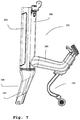
- the bias steering device 100 is provided with a stand 290.
- the stand 290 is attached to the connecting part 280 of the monocoque component 101 of the preload steering device 100. It will be understood by those skilled in the art that such a stand 290 can also be attached to other positions of a preload steering device.
- the stand 290 is provided with two rolling wheels arranged on a ground contacting portion of the stand.
- the stand makes it possible to hold the preload steering device 100 when it is decoupled from the wheelchair 300 in an assembly position in which the preload steering device 100 stands on the main wheel 105 and the two rolling wheels of the stand 290.
- roller wheels instead of the roller wheels, other components can also be used to bring the stand 200 into contact with the ground, wherein these components can be both movable components and rigid components.
- the wheels do not touch the ground on which the wheelchair combination 500 is standing. They are thus also lifted from the ground in relation to the installation position of the prestressing steering device 100, just as the front wheels 302 of the wheelchair 300 are lifted from the ground compared to a position in which the wheelchair, without being coupled to a prestressing steering device 100, is on its front wheels 302 and its rear wheels 301 stands.
- the stand 290 is connected to the preload steering device 100 at its upper end of the mounting portion.
- the rolling wheels are attached to the lower end of the ground contacting section.
- a spring device is arranged between the ground contacting section and the mounting section. The spring device enables the ground contact section to be able to pivot elastically with the roller wheels when it comes into contact with an obstacle. In particular, there is elastic pivoting in the direction of travel, that is to say in a direction that is shown in FIG Fig. 2 runs from left to right and vice versa, possible.
- the spring device can also be arranged at other locations on the stand, including the upper end of the stand, that is to say, in the embodiment shown, the upper end of the mounting section.
- an otherwise rigid stand for example, could thus be connected to a corresponding connecting part of a preload steering device with the interposition of a spring device.
- the spring device has two rubber-metal buffers which are screwed to a first carrier plate of the ground contact section and to a second carrier plate of the mounting section opposite the first carrier plate.
- Very suitable rubber-metal buffers of this type are, for example, vibration metal buffers from Reiff Technische Kunststoff GmbH, Reutlingen, Germany, in which an elastomer is arranged between two plates made of galvanized steel. These vibrating metal buffers have a circular cylindrical shape and have a spring stiffness in the direction of the cylinder axis which is considerably greater than the spring stiffness in the radial direction.
- two rubber-metal buffers of this type are arranged at a distance from one another in an arrangement direction which runs perpendicular to the straight-ahead driving direction of the wheelchair combination and parallel to the floor.
- the spring device thus has a spring stiffness in the straight-ahead driving direction that is lower than in a direction which is perpendicular to the straight-ahead driving direction of the wheelchair and parallel to the ground, the latter spring stiffness being even less than that in a direction perpendicular to the ground.
- the structure of the monocoque component 101, the hollow body 200 and the hollow body main part 201 and their interaction with corresponding components of the prestressing steering device 100 are described below.
- the monocoque component 101 has the hollow body 200.
- An essential element of the hollow body 200 is the hollow body main part 201.
- the connecting part 280 is fastened to the hollow body main part 201.
- the hollow body main part 201 can be made of aluminum, for example as an extruded profile.
- the connecting part 280 can also be made from Be made of aluminum, for example by means of a hydroforming process.
- the connection of the connecting part 280 to the hollow body main part 201 can take place by welding.
- the mounting arrangement 130 can have a component 131 which can be inserted into the connecting part 280 designed as a down tube, as well as a latching mechanism 132 which engages in a corresponding latching recess 281 of the connecting part 280 (see FIG Fig. 16 ).
- a head end cover 202 is attached.
- an accumulator that is, a rechargeable battery 203 can be used (see Fig. 16 ).
- the accumulator 203 is designed in such a way that, when it is inserted into the hollow body 200, it forms a harmonious surface with the latter, and has contact points which, when the accumulator 203 is inserted into the recess 205 of the hollow body 200 ready for operation, are in conductive engagement with electrical contacts 206 which are formed in the hollow body 200.
- a seat for an upper steering head bearing 240 and a seat for a lower steering head bearing 250 are arranged on the hollow body 200.
- the upper steering head bearing 240 and the lower steering head bearing 250 are used to support the steering shaft 141.
- An arrangement of the upper steering head bearing 240 and the lower steering head bearing 250 on the hollow body 200 within the meaning of the invention is an arrangement in which the hollow body provides structural support for the storage of the Steering shaft 141 provides. This can be done in various ways, in particular by the fact that the hollow body 200 interacts with on the one hand special configurations of areas of the hollow body 200 and on the other hand other components that are used to hold the upper steering head bearing 240 and the lower steering head bearing 250 on or in the hollow body 200 , this hold guaranteed.
- An exemplary embodiment of this storage shown in the figures is explained below, with particular reference to the Figures 11 to 14 is referred.
- An upper headset support plate 241 which can be made of aluminum and serves to hold the upper steering head bearing 240, is screwed to an upper end of the main hollow body part 201 by means of two screws.
- the handlebar holder 242 thus also functions as a headset holding element.
- a steering head bearing nut 243 made, for example, of steel is screwed onto a thread formed for this purpose on the steering shaft 141 and enables the arrangement and adjustment of the play of the steering head bearing to be maintained.
- the lower steering head bearing 250 is held between a lower headset support plate 251, for example made of aluminum, which is screwed to a lower end of the hollow body main part 201, and the fork crown 142.
- FIG. 11 shows a perspective view of the hollow body main part 201 and FIG Fig. 17
- FIG. 11 shows a plan view of the hollow body main part 201, that is to say a view from above, based on the illustration according to FIG Fig. 18 .
- the hollow body main part 201 according to the present embodiment is produced from aluminum by an extrusion process. It will be understood by those skilled in the art that numerous other materials, for example metals, metal alloys, plastics, and / or fiber composite materials, and other manufacturing and shaping processes can be selected.
- the hollow body 200 has a structural strength which enables the steering shaft 141 to be supported and thus can absorb the forces occurring during operation of the wheelchair combination 500, and on the other hand, at the same time, thanks to its design as a hollow body, Receiving space for both the steering shaft 141 and for function control transmission elements, in particular for hydraulic or pneumatic control lines, for example brake lines of hydraulic brakes, electrical lines such as cables, and elements for the mechanical transmission of forces, for example Bowden cables for brakes or mechanical switching mechanisms.
- the main hollow body part 201 according to the present embodiment is of particular importance because, in conjunction with the connecting part 280, it enables a monocoque structure in this regard.
- screw channels 261 are formed which are used for screwing to the upper headset carrier plate 241.
- screw channels 262 are formed which are used for screwing to the lower headset carrier plate 251.
- Further screw channels 263 at the upper end of the main hollow body part 201 are used for screwing to the head end cover 202.
- the screw channels can already be created in the extruded profile and the screwing can be carried out by means of thread-forming screws. It goes without saying that the person skilled in the art also has further alternatives in this regard, for example threads already provided in the extruded profile or the use of thread inserts.
- the hollow body main part 201 is designed in such a way that it has the frontal recess 205 for receiving the accumulator 203.
- a wall 271 is formed which, together with a corresponding part of the rear outer wall of the hollow body main part 201, defines a steering shaft shaft 270 for receiving the steering shaft 141.
- the wall 271 at the same time forms the rear wall of the recess 205.
- the wall 271, together with corresponding projections 273, forms function control transmission element shafts 275 for function control transmission elements.
- grommet recesses 277 for receiving grommets 278 (see in particular Figures 13 and 14th ) intended.
- the grommets 278 have flexible openings through which function control transmission elements can be passed.
- function control transmission elements hydraulic brake lines 108 are shown in the figures (see in particular Fig. 3 ).
- a brake lever 109 is attached to each handle of the handlebar 110, from which a hydraulic brake line 108 leads to a respective separate brake caliper of the disc brake 107. This results in additional security in that, although there is only one disc brake, it can be braked with either hand.
- This cable runs through a further opening in the head end cover 202, not explicitly shown in the figures. It goes without saying that further function control transmission elements, which are not shown in the figures for the sake of clarity, are provided and into or through the hollow body this can be laid through. This includes, for example, an electrical line that leads away from a control element designed in the manner of a throttle grip on motorcycles at the end of the handlebar 110 or a cable that leads away from a USB socket, which can be arranged on the head end cover 202, for example .
- Function control transfer element shafts 275 allow these function control transfer elements to be laid safely and avoid damage and contamination, as well as tangling or entanglement therein.
- the hollow body 200 ensures a high level of stability with regard to the mounting of the steering shaft and thus the guidance of the main wheel 105 while at the same time having a low mass compared to a solid component, such as a control tube known from bicycle construction.
Landscapes
- Health & Medical Sciences (AREA)
- Life Sciences & Earth Sciences (AREA)
- Animal Behavior & Ethology (AREA)
- General Health & Medical Sciences (AREA)
- Public Health (AREA)
- Veterinary Medicine (AREA)
- Motorcycle And Bicycle Frame (AREA)
- Steering Devices For Bicycles And Motorcycles (AREA)
Claims (12)
- Dispositif de direction auxiliaire (100) pour fauteuil roulant (300), le dispositif de direction auxiliaire (100) comportant au moins une roue (105) orientable grâce à un arbre de direction (141),
comprenant un corps creux (200), le corps creux (200) comportant :un logement pour un palier de tête de direction supérieur (240) logeant l'arbre de direction (141),un logement pour un palier de tête de direction inférieur (250) pour loger l'arbre de direction (141),un puits (270) d'arbre de direction pour accueillir l'arbre de direction (141),au moins un point d'introduction (277) d'au moins un élément de transmission de commande fonctionnelle (108, 265) etau moins un point de sortie (277) d'au moins un élément de transmission de commande fonctionnelle (108, 265),un élément de transmission de commande fonctionnelle (108, 265) étant un élément choisi dans un groupe d'éléments comprenant une conduite de commande hydraulique ou pneumatique (108), une conduite électrique (265) ou un élément de transmission mécanique de forces,caractérisé parun composant monocoque (101) réalisé sous forme d'un composant uniforme autoporteur comprenant le corps creux (200) comportant un tronçon principal de corps creux (201) ainsi qu'un élément de liaison (280),l'élément de liaison (280) servant à relier le dispositif de direction auxiliaire (100) au fauteuil roulant (300), etune paroi (271) étant conformée à l'intérieur du tronçon principal de corps creux (201) qui, ensemble avec un élément correspondant d'une paroi extérieure du tronçon principal de corps creux (201), définit un puits (270) d'arbre de direction pour accueillir l'arbre de direction. - Dispositif de direction auxiliaire (100) selon la revendication 1, caractérisé en ce que la paroi (271) définit, ensemble avec des ergots (273) correspondants, des puits d'éléments de transmission de commande fonctionnelle (275) pour des éléments de transmission de commande fonctionnelle.
- Dispositif de direction auxiliaire (100) selon la revendication 1 ou 2, caractérisé en ce que la paroi (271) définit, ensemble avec un élément correspondant d'une paroi extérieure arrière du tronçon principal de corps creux (201), un puits (270) d'arbre de direction pour accueillir l'arbre de direction.
- Dispositif de direction auxiliaire (100) selon la revendication 1,2 ou 3, caractérisé en ce que le tronçon principal de corps creux (201) présente un évidement (205) pour accueillir un accumulateur (203) et en ce que la paroi (271) définit une paroi arrière de l'évidement (205).
- Dispositif de direction auxiliaire (100) selon l'une des revendications précédentes, caractérisé en ce que le logement du palier de tête de direction supérieur (240) comprend une plaque de support du jeu de direction (241) supérieure ainsi qu'un élément support du jeu de direction (242), le palier de tête de direction supérieur (240) étant maintenu entre la plaque de support du jeu de direction (241) supérieure et l'élément support du jeu de direction (242).
- Dispositif de direction auxiliaire (100) selon la revendication 5, caractérisé en ce que l'arbre de direction (141) comprend un filetage et le jeu du palier de tête de direction est réglable grâce à une vis de palier de tête de direction (243) vissée sur le filetage de l'arbre de direction (141) via l'élément support du jeu de direction (242).
- Dispositif de direction auxiliaire (100) selon l'une des revendications précédentes 5 ou 6, caractérisé en ce que l'élément support du jeu de direction (242) est prévu sous forme d'attache de la barre de guidon (242).
- Dispositif de direction auxiliaire (100) selon l'une des revendications précédentes, caractérisé en ce que le logement du palier de tête de direction inférieur (250) présente une plaque de support du jeu de direction inférieure (251) le palier de tête de direction inférieur (250) étant maintenu entre la plaque de support du jeu de direction inférieure (251) et une couronne de fourche (142).
- Dispositif de direction auxiliaire (100) selon l'une des revendications précédentes, caractérisé en ce que le tronçon principal de corps creux (201) est réalisé comme composant uniforme grâce à un procédé d'extrusion.
- Dispositif de direction auxiliaire (100) selon l'une des revendications précédentes, caractérisé en ce que la pièce de liaison (280) est soudée au tronçon principal de corps creux (201).
- Dispositif de direction auxiliaire (100) selon la revendication 10, caractérisé en ce que la pièce de liaison (280) et le tronçon principal de corps creux (201) sont réalisés en aluminium, la réalisation du tronçon principal de corps creux (280) se faisant de préférence par un procédé d'hydroformage.
- Ensemble de fauteuil roulant (500) comportant un dispositif de direction auxiliaire (100) pour fauteuil roulant (300) selon l'une des revendications précédentes 1 à 11.
Applications Claiming Priority (1)
| Application Number | Priority Date | Filing Date | Title |
|---|---|---|---|
| DE102017130681.1A DE102017130681B3 (de) | 2017-12-20 | 2017-12-20 | Vorspannlenkvorrichtung für einen Rollstuhl und Rollstuhlgespann mit Vorspannlenkvorrichtung |
Publications (2)
| Publication Number | Publication Date |
|---|---|
| EP3501468A1 EP3501468A1 (fr) | 2019-06-26 |
| EP3501468B1 true EP3501468B1 (fr) | 2021-09-01 |
Family
ID=63998541
Family Applications (1)
| Application Number | Title | Priority Date | Filing Date |
|---|---|---|---|
| EP18202482.8A Active EP3501468B1 (fr) | 2017-12-20 | 2018-10-25 | Dispositif de précontrainte de direction pour un fauteuil roulant et fauteuil roulant comportant un dispositif de précontrainte de direction |
Country Status (2)
| Country | Link |
|---|---|
| EP (1) | EP3501468B1 (fr) |
| DE (1) | DE102017130681B3 (fr) |
Families Citing this family (3)
| Publication number | Priority date | Publication date | Assignee | Title |
|---|---|---|---|---|
| KR20220042693A (ko) * | 2020-09-28 | 2022-04-05 | 현대자동차주식회사 | 퍼스널 모빌리티의 견인모듈 및 이를 포함하는 퍼스널 모빌리티, 퍼스널 모빌리티의 제어방법 |
| KR200498003Y1 (ko) * | 2022-08-22 | 2024-05-17 | 주식회사 프론테크 | 휠체어의 보조 동력원을 제공하기 위한 전동보조장치 |
| KR102666603B1 (ko) * | 2022-08-22 | 2024-05-20 | 주식회사 프론테크 | 휠체어의 보조 동력원을 제공하기 위한 전동보조장치 |
Family Cites Families (10)
| Publication number | Priority date | Publication date | Assignee | Title |
|---|---|---|---|---|
| DE840575C (de) | 1949-01-16 | 1952-06-03 | Karl Willuhn | Zimmerfahrstuhl mit Handantrieb fuer Koerperbehinderte |
| US2892506A (en) * | 1956-01-17 | 1959-06-30 | James A Slater | Electrically driven invalid chair |
| US3023825A (en) * | 1958-11-17 | 1962-03-06 | Rabjohn Rodney Robert | Power operated wheel chair |
| US3213957A (en) * | 1962-08-27 | 1965-10-26 | Wessex Ind Poole Ltd | Self-propelled wheel chair |
| US3387681A (en) * | 1966-02-14 | 1968-06-11 | Rodney R. Rabjohn | Power operated wheel chair |
| US5651422A (en) * | 1994-04-22 | 1997-07-29 | The Center For Innovative Technology | Universal-fit, quick-connect power drive/steer attachment for wheelchair |
| DE19857786C2 (de) | 1998-03-21 | 2000-05-31 | Alber Ulrich Gmbh & Co Kg | Hilfsantriebsvorrichtung für Selbstfahrer-Rollstühle |
| CA2527727A1 (fr) * | 2003-05-30 | 2004-12-09 | Izumi, D.O.O. | Mecanisme de direction supplementaire pour vehicule actionne musculairement, destine a accelerer la reeducation d'un bras paralyse |
| US7216728B2 (en) * | 2004-07-02 | 2007-05-15 | Chao-Kuo Huang | Motorized apparatus for towing a wheelchair |
| ES2425316B1 (es) | 2013-07-08 | 2014-08-05 | Batec Mobility, S.L. | Sistema auxiliar de movilidad para silla de ruedas |
-
2017
- 2017-12-20 DE DE102017130681.1A patent/DE102017130681B3/de active Active
-
2018
- 2018-10-25 EP EP18202482.8A patent/EP3501468B1/fr active Active
Also Published As
| Publication number | Publication date |
|---|---|
| EP3501468A1 (fr) | 2019-06-26 |
| DE102017130681B3 (de) | 2019-02-07 |
Similar Documents
| Publication | Publication Date | Title |
|---|---|---|
| EP3501468B1 (fr) | Dispositif de précontrainte de direction pour un fauteuil roulant et fauteuil roulant comportant un dispositif de précontrainte de direction | |
| DE102018206225B4 (de) | Roller und Verfahren zum Bedienen eines Rollers | |
| DE112011101993T5 (de) | Freihändig bedienbarer elektrischer Roller | |
| DE202009019179U1 (de) | Hilfsantrieb | |
| EP3622930B1 (fr) | Dispositif d'entraînement auxiliaire pour fauteuil roulant | |
| DE2025795A1 (de) | Elektrisch angetriebenes Vierrad-Einzel-Fahrzeug | |
| EP3317172B1 (fr) | Véhicule à axe de direction incliné | |
| EP3347263B1 (fr) | Véhicule à équilibrage dynamique | |
| DE10309621A1 (de) | Motorgetriebenes, handgeführtes Transportfahrzeug mit intuitiver Haltegriffsteuerung | |
| DE19723973A1 (de) | Verteiler- bzw. Zustellerwagen | |
| EP3501469B1 (fr) | Support, dispositif de précontrainte de direction pourvu de support et attelage de fauteuil roulant pourvu de dispositif de précontrainte de direction | |
| DE10259684A1 (de) | Lenkhandhabe für ein Kraftfahrzeug | |
| DE102018124575B4 (de) | Verfahrbarer Ladelift mit fernbedienter Schwenkarretierungseinheit für die Lenkrollen | |
| EP0811469B1 (fr) | Véhicule de distribution ou de transport | |
| DE102018122368A1 (de) | Antriebsvorrichtung für einen Rollstuhl | |
| DE202018006256U1 (de) | Hilfsantriebsvorrichtung für einen Rollstuhl | |
| EP3622931B1 (fr) | Dispositif d'entraînement auxiliaire pour fauteuil roulant | |
| WO2021175985A1 (fr) | Véhicule à une ou plusieurs voies ayant une conception de cadre améliorée | |
| DE102009055025A1 (de) | Längenverstellbare Lenkbetätigungseinheit für ein Kraftfahrzeug mit einem Träger und mit einer Lenksäule | |
| DE102018122367A1 (de) | Antriebsvorrichtung für einen Rollstuhl | |
| DE202018006204U1 (de) | Hilfsantriebsvorrichtung für einen Rollstuhl | |
| DE102016015269A1 (de) | Fahrzeugsitz | |
| DE102009009411A1 (de) | Fahrhilfe für ein Kraftfahrzeug | |
| EP1298023A1 (fr) | Véhicule de distribution ou de transport | |
| DE102015202546B4 (de) | Motorisiertes niederfluriges Fahrzeug |
Legal Events
| Date | Code | Title | Description |
|---|---|---|---|
| PUAI | Public reference made under article 153(3) epc to a published international application that has entered the european phase |
Free format text: ORIGINAL CODE: 0009012 |
|
| STAA | Information on the status of an ep patent application or granted ep patent |
Free format text: STATUS: THE APPLICATION HAS BEEN PUBLISHED |
|
| AK | Designated contracting states |
Kind code of ref document: A1 Designated state(s): AL AT BE BG CH CY CZ DE DK EE ES FI FR GB GR HR HU IE IS IT LI LT LU LV MC MK MT NL NO PL PT RO RS SE SI SK SM TR |
|
| AX | Request for extension of the european patent |
Extension state: BA ME |
|
| STAA | Information on the status of an ep patent application or granted ep patent |
Free format text: STATUS: REQUEST FOR EXAMINATION WAS MADE |
|
| 17P | Request for examination filed |
Effective date: 20191217 |
|
| RBV | Designated contracting states (corrected) |
Designated state(s): AL AT BE BG CH CY CZ DE DK EE ES FI FR GB GR HR HU IE IS IT LI LT LU LV MC MK MT NL NO PL PT RO RS SE SI SK SM TR |
|
| RAP3 | Party data changed (applicant data changed or rights of an application transferred) |
Owner name: ALBER GMBH |
|
| GRAP | Despatch of communication of intention to grant a patent |
Free format text: ORIGINAL CODE: EPIDOSNIGR1 |
|
| STAA | Information on the status of an ep patent application or granted ep patent |
Free format text: STATUS: GRANT OF PATENT IS INTENDED |
|
| INTG | Intention to grant announced |
Effective date: 20210622 |
|
| GRAS | Grant fee paid |
Free format text: ORIGINAL CODE: EPIDOSNIGR3 |
|
| GRAA | (expected) grant |
Free format text: ORIGINAL CODE: 0009210 |
|
| STAA | Information on the status of an ep patent application or granted ep patent |
Free format text: STATUS: THE PATENT HAS BEEN GRANTED |
|
| AK | Designated contracting states |
Kind code of ref document: B1 Designated state(s): AL AT BE BG CH CY CZ DE DK EE ES FI FR GB GR HR HU IE IS IT LI LT LU LV MC MK MT NL NO PL PT RO RS SE SI SK SM TR |
|
| REG | Reference to a national code |
Ref country code: GB Ref legal event code: FG4D Free format text: NOT ENGLISH |
|
| REG | Reference to a national code |
Ref country code: CH Ref legal event code: EP Ref country code: AT Ref legal event code: REF Ref document number: 1425429 Country of ref document: AT Kind code of ref document: T Effective date: 20210915 |
|
| REG | Reference to a national code |
Ref country code: DE Ref legal event code: R096 Ref document number: 502018006809 Country of ref document: DE |
|
| REG | Reference to a national code |
Ref country code: IE Ref legal event code: FG4D Free format text: LANGUAGE OF EP DOCUMENT: GERMAN |
|
| REG | Reference to a national code |
Ref country code: LT Ref legal event code: MG9D |
|
| REG | Reference to a national code |
Ref country code: NL Ref legal event code: MP Effective date: 20210901 |
|
| PG25 | Lapsed in a contracting state [announced via postgrant information from national office to epo] |
Ref country code: LT Free format text: LAPSE BECAUSE OF FAILURE TO SUBMIT A TRANSLATION OF THE DESCRIPTION OR TO PAY THE FEE WITHIN THE PRESCRIBED TIME-LIMIT Effective date: 20210901 Ref country code: BG Free format text: LAPSE BECAUSE OF FAILURE TO SUBMIT A TRANSLATION OF THE DESCRIPTION OR TO PAY THE FEE WITHIN THE PRESCRIBED TIME-LIMIT Effective date: 20211201 Ref country code: NO Free format text: LAPSE BECAUSE OF FAILURE TO SUBMIT A TRANSLATION OF THE DESCRIPTION OR TO PAY THE FEE WITHIN THE PRESCRIBED TIME-LIMIT Effective date: 20211201 Ref country code: HR Free format text: LAPSE BECAUSE OF FAILURE TO SUBMIT A TRANSLATION OF THE DESCRIPTION OR TO PAY THE FEE WITHIN THE PRESCRIBED TIME-LIMIT Effective date: 20210901 Ref country code: FI Free format text: LAPSE BECAUSE OF FAILURE TO SUBMIT A TRANSLATION OF THE DESCRIPTION OR TO PAY THE FEE WITHIN THE PRESCRIBED TIME-LIMIT Effective date: 20210901 Ref country code: ES Free format text: LAPSE BECAUSE OF FAILURE TO SUBMIT A TRANSLATION OF THE DESCRIPTION OR TO PAY THE FEE WITHIN THE PRESCRIBED TIME-LIMIT Effective date: 20210901 Ref country code: SE Free format text: LAPSE BECAUSE OF FAILURE TO SUBMIT A TRANSLATION OF THE DESCRIPTION OR TO PAY THE FEE WITHIN THE PRESCRIBED TIME-LIMIT Effective date: 20210901 Ref country code: RS Free format text: LAPSE BECAUSE OF FAILURE TO SUBMIT A TRANSLATION OF THE DESCRIPTION OR TO PAY THE FEE WITHIN THE PRESCRIBED TIME-LIMIT Effective date: 20210901 |
|
| PG25 | Lapsed in a contracting state [announced via postgrant information from national office to epo] |
Ref country code: PL Free format text: LAPSE BECAUSE OF FAILURE TO SUBMIT A TRANSLATION OF THE DESCRIPTION OR TO PAY THE FEE WITHIN THE PRESCRIBED TIME-LIMIT Effective date: 20210901 Ref country code: LV Free format text: LAPSE BECAUSE OF FAILURE TO SUBMIT A TRANSLATION OF THE DESCRIPTION OR TO PAY THE FEE WITHIN THE PRESCRIBED TIME-LIMIT Effective date: 20210901 Ref country code: GR Free format text: LAPSE BECAUSE OF FAILURE TO SUBMIT A TRANSLATION OF THE DESCRIPTION OR TO PAY THE FEE WITHIN THE PRESCRIBED TIME-LIMIT Effective date: 20211202 |
|
| REG | Reference to a national code |
Ref country code: CH Ref legal event code: PL |
|
| PG25 | Lapsed in a contracting state [announced via postgrant information from national office to epo] |
Ref country code: IS Free format text: LAPSE BECAUSE OF FAILURE TO SUBMIT A TRANSLATION OF THE DESCRIPTION OR TO PAY THE FEE WITHIN THE PRESCRIBED TIME-LIMIT Effective date: 20220101 Ref country code: SM Free format text: LAPSE BECAUSE OF FAILURE TO SUBMIT A TRANSLATION OF THE DESCRIPTION OR TO PAY THE FEE WITHIN THE PRESCRIBED TIME-LIMIT Effective date: 20210901 Ref country code: SK Free format text: LAPSE BECAUSE OF FAILURE TO SUBMIT A TRANSLATION OF THE DESCRIPTION OR TO PAY THE FEE WITHIN THE PRESCRIBED TIME-LIMIT Effective date: 20210901 Ref country code: RO Free format text: LAPSE BECAUSE OF FAILURE TO SUBMIT A TRANSLATION OF THE DESCRIPTION OR TO PAY THE FEE WITHIN THE PRESCRIBED TIME-LIMIT Effective date: 20210901 Ref country code: PT Free format text: LAPSE BECAUSE OF FAILURE TO SUBMIT A TRANSLATION OF THE DESCRIPTION OR TO PAY THE FEE WITHIN THE PRESCRIBED TIME-LIMIT Effective date: 20220103 Ref country code: NL Free format text: LAPSE BECAUSE OF FAILURE TO SUBMIT A TRANSLATION OF THE DESCRIPTION OR TO PAY THE FEE WITHIN THE PRESCRIBED TIME-LIMIT Effective date: 20210901 Ref country code: EE Free format text: LAPSE BECAUSE OF FAILURE TO SUBMIT A TRANSLATION OF THE DESCRIPTION OR TO PAY THE FEE WITHIN THE PRESCRIBED TIME-LIMIT Effective date: 20210901 Ref country code: CZ Free format text: LAPSE BECAUSE OF FAILURE TO SUBMIT A TRANSLATION OF THE DESCRIPTION OR TO PAY THE FEE WITHIN THE PRESCRIBED TIME-LIMIT Effective date: 20210901 Ref country code: AL Free format text: LAPSE BECAUSE OF FAILURE TO SUBMIT A TRANSLATION OF THE DESCRIPTION OR TO PAY THE FEE WITHIN THE PRESCRIBED TIME-LIMIT Effective date: 20210901 |
|
| REG | Reference to a national code |
Ref country code: DE Ref legal event code: R097 Ref document number: 502018006809 Country of ref document: DE |
|
| REG | Reference to a national code |
Ref country code: BE Ref legal event code: MM Effective date: 20211031 |
|
| PG25 | Lapsed in a contracting state [announced via postgrant information from national office to epo] |
Ref country code: MC Free format text: LAPSE BECAUSE OF FAILURE TO SUBMIT A TRANSLATION OF THE DESCRIPTION OR TO PAY THE FEE WITHIN THE PRESCRIBED TIME-LIMIT Effective date: 20210901 |
|
| PLBE | No opposition filed within time limit |
Free format text: ORIGINAL CODE: 0009261 |
|
| STAA | Information on the status of an ep patent application or granted ep patent |
Free format text: STATUS: NO OPPOSITION FILED WITHIN TIME LIMIT |
|
| PG25 | Lapsed in a contracting state [announced via postgrant information from national office to epo] |
Ref country code: LU Free format text: LAPSE BECAUSE OF NON-PAYMENT OF DUE FEES Effective date: 20211025 Ref country code: IT Free format text: LAPSE BECAUSE OF FAILURE TO SUBMIT A TRANSLATION OF THE DESCRIPTION OR TO PAY THE FEE WITHIN THE PRESCRIBED TIME-LIMIT Effective date: 20210901 Ref country code: DK Free format text: LAPSE BECAUSE OF FAILURE TO SUBMIT A TRANSLATION OF THE DESCRIPTION OR TO PAY THE FEE WITHIN THE PRESCRIBED TIME-LIMIT Effective date: 20210901 Ref country code: BE Free format text: LAPSE BECAUSE OF NON-PAYMENT OF DUE FEES Effective date: 20211031 |
|
| 26N | No opposition filed |
Effective date: 20220602 |
|
| PG25 | Lapsed in a contracting state [announced via postgrant information from national office to epo] |
Ref country code: SI Free format text: LAPSE BECAUSE OF FAILURE TO SUBMIT A TRANSLATION OF THE DESCRIPTION OR TO PAY THE FEE WITHIN THE PRESCRIBED TIME-LIMIT Effective date: 20210901 Ref country code: LI Free format text: LAPSE BECAUSE OF NON-PAYMENT OF DUE FEES Effective date: 20211031 Ref country code: CH Free format text: LAPSE BECAUSE OF NON-PAYMENT OF DUE FEES Effective date: 20211031 |
|
| PG25 | Lapsed in a contracting state [announced via postgrant information from national office to epo] |
Ref country code: FR Free format text: LAPSE BECAUSE OF NON-PAYMENT OF DUE FEES Effective date: 20211101 |
|
| PG25 | Lapsed in a contracting state [announced via postgrant information from national office to epo] |
Ref country code: IE Free format text: LAPSE BECAUSE OF NON-PAYMENT OF DUE FEES Effective date: 20211025 |
|
| P01 | Opt-out of the competence of the unified patent court (upc) registered |
Effective date: 20230504 |
|
| GBPC | Gb: european patent ceased through non-payment of renewal fee |
Effective date: 20221025 |
|
| PG25 | Lapsed in a contracting state [announced via postgrant information from national office to epo] |
Ref country code: CY Free format text: LAPSE BECAUSE OF FAILURE TO SUBMIT A TRANSLATION OF THE DESCRIPTION OR TO PAY THE FEE WITHIN THE PRESCRIBED TIME-LIMIT Effective date: 20210901 |
|
| PG25 | Lapsed in a contracting state [announced via postgrant information from national office to epo] |
Ref country code: HU Free format text: LAPSE BECAUSE OF FAILURE TO SUBMIT A TRANSLATION OF THE DESCRIPTION OR TO PAY THE FEE WITHIN THE PRESCRIBED TIME-LIMIT; INVALID AB INITIO Effective date: 20181025 |
|
| PG25 | Lapsed in a contracting state [announced via postgrant information from national office to epo] |
Ref country code: GB Free format text: LAPSE BECAUSE OF NON-PAYMENT OF DUE FEES Effective date: 20221025 |
|
| REG | Reference to a national code |
Ref country code: DE Ref legal event code: R082 Ref document number: 502018006809 Country of ref document: DE Representative=s name: RUEGER ABEL PATENTANWAELTE PARTGMBB, DE |
|
| PGFP | Annual fee paid to national office [announced via postgrant information from national office to epo] |
Ref country code: DE Payment date: 20231017 Year of fee payment: 6 |
|
| PG25 | Lapsed in a contracting state [announced via postgrant information from national office to epo] |
Ref country code: MK Free format text: LAPSE BECAUSE OF FAILURE TO SUBMIT A TRANSLATION OF THE DESCRIPTION OR TO PAY THE FEE WITHIN THE PRESCRIBED TIME-LIMIT Effective date: 20210901 |