EP3500489B1 - Sitzanordnung, insbesondere für ein flugzeug - Google Patents
Sitzanordnung, insbesondere für ein flugzeug Download PDFInfo
- Publication number
- EP3500489B1 EP3500489B1 EP17751779.4A EP17751779A EP3500489B1 EP 3500489 B1 EP3500489 B1 EP 3500489B1 EP 17751779 A EP17751779 A EP 17751779A EP 3500489 B1 EP3500489 B1 EP 3500489B1
- Authority
- EP
- European Patent Office
- Prior art keywords
- wall
- seat unit
- seats
- seat
- arrangement
- Prior art date
- Legal status (The legal status is an assumption and is not a legal conclusion. Google has not performed a legal analysis and makes no representation as to the accuracy of the status listed.)
- Active
Links
Images





Classifications
-
- B—PERFORMING OPERATIONS; TRANSPORTING
- B64—AIRCRAFT; AVIATION; COSMONAUTICS
- B64D—EQUIPMENT FOR FITTING IN OR TO AIRCRAFT; FLIGHT SUITS; PARACHUTES; ARRANGEMENT OR MOUNTING OF POWER PLANTS OR PROPULSION TRANSMISSIONS IN AIRCRAFT
- B64D11/00—Passenger or crew accommodation; Flight-deck installations not otherwise provided for
- B64D11/06—Arrangements of seats, or adaptations or details specially adapted for aircraft seats
- B64D11/0639—Arrangements of seats, or adaptations or details specially adapted for aircraft seats with features for adjustment or converting of seats
- B64D11/0641—Seats convertible into beds
-
- B—PERFORMING OPERATIONS; TRANSPORTING
- B64—AIRCRAFT; AVIATION; COSMONAUTICS
- B64D—EQUIPMENT FOR FITTING IN OR TO AIRCRAFT; FLIGHT SUITS; PARACHUTES; ARRANGEMENT OR MOUNTING OF POWER PLANTS OR PROPULSION TRANSMISSIONS IN AIRCRAFT
- B64D11/00—Passenger or crew accommodation; Flight-deck installations not otherwise provided for
- B64D11/06—Arrangements of seats, or adaptations or details specially adapted for aircraft seats
- B64D11/0601—Arrangement of seats for non-standard seating layouts, e.g. seats staggered horizontally or vertically, arranged in an angled or fishbone layout, or facing in other directions than the direction of flight
-
- B—PERFORMING OPERATIONS; TRANSPORTING
- B64—AIRCRAFT; AVIATION; COSMONAUTICS
- B64D—EQUIPMENT FOR FITTING IN OR TO AIRCRAFT; FLIGHT SUITS; PARACHUTES; ARRANGEMENT OR MOUNTING OF POWER PLANTS OR PROPULSION TRANSMISSIONS IN AIRCRAFT
- B64D11/00—Passenger or crew accommodation; Flight-deck installations not otherwise provided for
- B64D11/06—Arrangements of seats, or adaptations or details specially adapted for aircraft seats
- B64D11/0602—Seat modules, i.e. seat systems including furniture separate from the seat itself
- B64D11/0604—Seat modules, i.e. seat systems including furniture separate from the seat itself including a bed, e.g. cocoon type passenger seat modules
-
- B—PERFORMING OPERATIONS; TRANSPORTING
- B64—AIRCRAFT; AVIATION; COSMONAUTICS
- B64D—EQUIPMENT FOR FITTING IN OR TO AIRCRAFT; FLIGHT SUITS; PARACHUTES; ARRANGEMENT OR MOUNTING OF POWER PLANTS OR PROPULSION TRANSMISSIONS IN AIRCRAFT
- B64D11/00—Passenger or crew accommodation; Flight-deck installations not otherwise provided for
- B64D11/06—Arrangements of seats, or adaptations or details specially adapted for aircraft seats
- B64D11/0606—Arrangements of seats, or adaptations or details specially adapted for aircraft seats with privacy shells, screens, separators or the like
Definitions
- the present invention relates to an arrangement of seats, in particular seats for passengers of a transport vehicle, in particular of an airplane.
- the invention aims to provide such an arrangement of seats which ensures both the comfort and the safety of the passengers, while providing for their privacy to be preserved.
- the invention thus finds a particularly advantageous application with aircraft seats.
- the "Business Class” type airplane seats offer passengers different comfort positions, from a “seated” position to a “berth” position, in which the seat defines a substantially horizontal lying surface so that the passenger can lie down.
- Intermediate comfort positions are also available, such as the “relax” position in which the backrest is strongly inclined.
- these intermediate positions are obtained by the inclination of the pivoting backrest about a horizontal axis and perpendicular to an axis of extension of the seat. The passenger can then remain in the seat during transitions between the different positions.
- WO2014155353A1 discloses a seating arrangement comprising a closure system.
- the berth generally consists in particular of the backrest, the seat, a legrest and a footrest, the latter possibly being fixed or linked to the kinematics of the seat.
- Certain seating arrangements for an aircraft cabin of the "Business Class” type allow direct access to a traffic lane for all passengers, via a passage arranged between two seats arranged one behind the other along a longitudinal axis of the passenger compartment. aircraft cabin. Passengers can thus get out of their seat easily, especially when the seat is in the “bunk” position.
- the invention aims in particular to effectively remedy this drawback by proposing an arrangement of seats, in particular intended to be installed in an aircraft cabin, defined in independent claim 1.
- the invention thus makes it possible to define an enclosed interior space around the seat providing a feeling of privacy to the passenger by preventing him from being in direct sight of other passengers and / or on-board personnel walking in the traffic lane.
- the seat is turned towards a circulation corridor of the aircraft cabin.
- the closure means comprise at least one sliding wall, in particular rigid or flexible.
- the second direction of deployment of the second wall is opposite to the first direction of deployment of the first wall.
- the seat unit is equipped with a first wall and a second wall mounted movable relative to the seat unit.
- the first wall and the second wall are located on either side of an intermediate wall, in particular constituted by a portion of a fixed shell of the seat unit.
- the first wall is integral with at least one slideway cooperating with a rail fixed to the intermediate wall and / or in that the second wall is integral with at least one slide cooperating with a rail fixed to the intermediate wall.
- the intermediate wall has a corrugated shape defining hollows, two successive hollows being open in two opposite directions, rails of one of the walls from among the first or the second walls being housed in hollows open towards the seat. and rails of the other of the first and second walls being received in recesses open in a direction opposite to the seat.
- a cover extends above at least one corresponding rail in order to avoid risks of pinching the fingers when handling the first wall or the second wall.
- a lower part of the first wall and / or of the second wall is housed in a side cabinet of the corresponding seat unit respectively when the first wall and / or the second wall is in the stored position.
- the first wall and the second wall are movable according to a translational or rotational movement, or a combined movement comprising at least one translation and at least one rotation.
- the closing means comprise at least one blackout curtain.
- the support is movable in translation and / or in rotation with respect to the “front” seat unit to go from the “stowed” position to the “deployed” position.
- the closing means comprise a first curtain and / or a second curtain, in particular which can be rolled up and in particular installed in the "front" seat unit, the first curtain making it possible, when it is unrolled, to close the shutter.
- the transverse passage in particular a lower part of the transverse passage, and / or the second curtain making it possible to close, when it is unrolled, at least part of the transverse passage, in particular an upper part of the transverse passage.
- the closure means comprise at least two walls movable relative to each other according to at least one degree of freedom and capable of being deployed in the same direction of deployment or in two distinct directions.
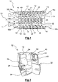
- the figure 1 shows an aircraft cabin 10 extending along a longitudinal axis X1 comprising an arrangement of seats 11.
- the arrangement of seats 11 according to the present invention comprises a plurality of seat units 12 respectively comprising an individual seat 13.
- the seat 13 is able to move from a “seated” position, corresponding to the position used in particular during the stopping, take-off and landing phases of the airplane, and a “bunk” position, in which the seat 13 defines a substantially horizontal lying surface for the passenger.
- the “seated” position and the “bunk” position constitute configurations of the seat 13 in two extreme positions.
- the seat 13 may also take intermediate positions, called relax positions, between these two extreme positions.
- the plurality of seat units 12 are ideally arranged in at least one row 15a extending preferably along the longitudinal axis X1 of the aircraft cabin 10. According to the example presented in FIG. figure 1 , the plurality of seating units 12 are conveniently arranged in four rows 15a, 15b, 15c and 15d.
- the seating unit 12 can be oriented such that the seat 13 faces forward and / or towards the rear of the aircraft.
- the terms “front” and “rear” used in relation to the expression “seat unit” locally define a relative position of the seat 13 inside the row 15a. , respectively the rows 15a, 15b, 15c and 15d, and do not refer in any way to an orientation of the seat 13 inside the aircraft cabin 10.
- the expression “seat unit” before “' means that the seat unit is positioned directly in front of another seat unit within the row, while the term 'rear' seat unit means that the seat unit is positioned directly behind another seat unit. seat inside the row.
- the arrangement of seats 11 comprises two side groups 16a, 16b comprising seating units 12.
- the two side groups 16a, 16b are respectively formed by two rows 15a, 15b of seat units 12. positioned along a side wall 17 of the fuselage of the aircraft cabin 10.
- the arrangement of seats 11 also comprises a central group 20.
- the central group 20 is preferably made up of two rows 15c, 15d of seat units 12. In such an arrangement, the two rows 15c, 15d of seat units 12 are particularly contiguous laterally with respect to one another.
- the side groups 16a, 16b are respectively separated from the central group 20 by a circulation corridor 21. According to the configuration presented in figure 1 , two traffic lanes 21 are therefore provided in the aircraft cabin 10, specifically between each side group 16a, 16b and the central group 20. As a variant, the two side groups 16a, 16b could each be formed by several rows of seating units 12.
- Each seat 13 has an axis of extension X2 corresponding substantially to a direction of longitudinal extension of the seat 13.
- the axis of extension X2 corresponds to the direction of longitudinal extension of the seat 13 in the “berth” position.
- the axis of extension X2 forms a non-zero angle with the longitudinal axis X1 of the aircraft cabin 10.
- each seat 13 is turned towards the circulation corridor 21 adjacent to the row 15a, respectively the rows 15a, 15b, 15c and 15d.
- each passenger has direct access to the traffic lane 21 from the seat 13.
- direct access to the traffic lane 21 is facilitated by the fact that the passenger's feet are located on the side of the traffic lane 21. .
- two seating units 12 are disposed laterally contiguous with respect to each other.
- the two seat units 12 have seats 13 extending in two distinct directions.
- the respective extension axes X2 of the two seating units 12 form an acute angle.
- Such a configuration is such that the two seating units 12 form a "V".
- a tip of the "V" shape of the two seat units 12 is located behind respective backrests 24 of the two seat units 12.
- the extension axes X2 of the seats 13 can form substantially the same angle with respect to the longitudinal axis X1 of the aircraft cabin 10.
- the extension axes X2 of two seats 13 adjacent to the central group 20 may intersect the longitudinal axis X1 of the aircraft cabin 10 at substantially the same point.
- the two laterally adjacent seats 13 can be offset with respect to each other along the longitudinal axis X1, so that the extension axes X2 of the two laterally adjacent seats 13 intersect the longitudinal axis X1 at different points.
- the seats 13 are oriented towards the front of the aircraft cabin 10, that is to say in the direction of a zone comprising a cockpit from the plane. In an alternative embodiment, the seats 13 are oriented towards the rear of the aircraft cabin 10, that is to say in the direction of an opposite area of the aircraft cockpit.
- each seat unit 12 therefore comprises a seat 13.
- the seat 13 comprises a backrest 24, in particular adjustable in inclination and a seat 25, in particular potentially adjustable in inclination.
- the seat 13 may include a legrest 26, in particular adjustable in inclination.
- the seat unit 12 may include a footrest 27, in particular visible in figure 6 .
- the footrest 27 may consist of a fixed cushion 28, in particular arranged in a housing 29 dedicated to receiving the feet of the passenger.
- the fixed cushion 28 of the footrest 27 is located in the extension of the seat 13 when the latter is in the “berth” position.
- the footrest 27 may consist of an element located at the end of the legrest 26.
- the seat unit 12 may also include a side cabinet 32, capable in particular of serving as a fixed shelf and / or a meal shelf storage.
- the seat unit 12 may also include a fixed shell 33 capable of ensuring separation.
- a fixed shell 33 therefore makes it possible to guarantee the privacy of each passenger.
- the fixed shell 33 extends around the backrest 24 of the seat 13 in order to create an interior space, wholly or partly closed, in which the seat 13 is arranged. .
- the two seat units 12 are arranged so as to define a vertical overlap, at least partially, between them.
- the vertical overlap between the two seat units 12 may consist, as shown, in a positioning of the housing 29 of the footrest 27 of the “rear” seat unit 12 under the side cabinet 32 of the corresponding “front” seat unit 12.
- the seat unit 12 may include an armrest 34.
- the armrest 34 may be retractable such that it is movable between a "raised” position in which the armrest 34 is adapted to support a part of the body. of the passenger, in particular an arm of the passenger, and a “stored” position in which the armrest 34 is able to be positioned at the same level as the seat base 25 of the seat 13, in particular when the latter is in a seated position.
- the passenger will thus be able to take advantage of comfortable positions by placing, for example, a part of his body, in particular a leg, on the armrest 34 in the “stored” position.
- the seat unit 12 may optionally include a fixed cushion (not shown).
- the fixed cushion allows a maximization of the sleeping arrangements.
- it is advantageously intended to be positioned in an extension of the seat 13, in particular a lateral extension, when the latter is in the “berth” position.
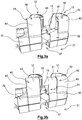
- a transverse passage 37 is formed between two consecutive seat units 12 of a row 15a, respectively the rows 15a, 15b, 15c and 15d, namely a “front” seat unit 12 and a “rear” seat unit 12 . More specifically according to the exemplary embodiment presented, the transverse passage 37 extends between the “rear” seat unit 12 and the fixed shell 33 of the seat unit 12. " before ".
- the transverse passage 37 is arranged so as to allow movement of the passenger from the seat 13 to the circulation corridor 21, in particular when the seat 13 is in the “berth” position.
- closing means 40 in particular removable closing means 40, are arranged in the transverse passage 37.
- the closing means 40 are suitable for ensuring the closing of the transverse passage 37.
- Such closing means 40 thus make it possible to define, in particular in cooperation with the fixed shell 33 of the seat unit 12, an enclosed space around the seat 13.
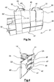
- the closure means 40 When the closure means 40 are deployed, as illustrated in particular on the figures 3c and 6 , the transverse passage 37 formed between two consecutive seat units 12 of row 15a, respectively rows 15a, 15b, 15c, 15d, is closed by the closing means 40, such as for example walls and / or curtains.
- the passenger seated in the seat 13 is separated from any passenger and / or on-board staff walking in the traffic lane 21 by the closure means 40 in cooperation with the fixed shell 33 extending around the seat 13.
- the passenger is thus seated in a zone of privacy defined by the enclosed space thus created.
- the closure means 40 comprise at least a first wall 41.
- the first wall 41 extends in a substantially vertical plane.
- the first wall 41 is able to slide, in a first direction D1, relative to the seat unit 12, in particular by relative to an intermediate wall 42 of the seat unit 12, in particular the intermediate wall 42 of the “rear” seat unit 12.
- first wall 41 extends along a substantially vertical plane.
- closure means 40 comprise at least one second wall 43.
- the second wall 43 is able to slide in a second direction D2 relative to the seat unit 12, in particular relative to the intermediate wall 42 of the seat unit 12, in particular the intermediate wall 42 of the "front" seat unit 12.
- the second direction D2 according to which the second wall 43 moves is opposite to the first direction D1 according to which the first wall 41 moves.
- the first direction D1 and the second direction D2 are, preferably, parallel to the longitudinal axis X1 of the aircraft cabin 10.
- the parts of the transverse passage 37 closed by the first wall 41 and the second wall 43 are advantageously complementary along the longitudinal axis X1, so that the transverse passage 37 is closed along its entire longitudinal dimension.
- the first wall 41 can also close off a space located above the side cabinet 32 of the “rear” seat unit 12.
- the second wall 43 can also close off the rest of the transverse passage 37 between the two seat units 12.
- the first wall 41 and the second wall 43 When the first wall 41 and the second wall 43 are moved to the “deployed” position, the first wall 41 and the second wall 43 preferably comprise edges that are substantially contiguous. As a variant, the edges of the first wall 41 and of the second wall 43 may be slightly spaced with respect to one another.
- the first wall 41 extends only over an upper part of the seat unit 12. In such an arrangement, a portion of a lower part of the transverse passage 37 is closed by the side cabinet 32.
- the second wall 43 extends over an upper part and a lower part of the seat unit 12. In variant, the second wall 43 extends only over an upper part, as illustrated by figure 9 .
- the seat unit 12 is equipped with a first wall 41 and / or a second wall 43 mounted to slide relative to an intermediate wall 42, advantageously fixed relative to the seat unit 12.
- the first wall 41 and the second wall 43 are located on either side of the intermediate wall 42.
- the first wall 41 and the second wall 43 are respectively integral with at least one slideway 46 cooperating with at least one rail 47 , in particular fixed to the intermediate wall 42.
- the first wall 41, respectively the second wall 43 may include a fixing lug 48 establishing the connection between the first wall 41, respectively the second wall 43, and the slideway 46.
- the seat unit 12 could, for example, include three rails 47 located respectively in the lower part, in the upper part and in an intermediate zone of the intermediate wall 42.
- the intermediate wall 42 preferably has a corrugated shape, each corrugation defining a hollow 50.
- two successive hollows 50 are open in two opposite directions.
- the rails 47 of one of the walls among the first wall 41 and the second wall 43 are housed in recesses 50 open towards the seat 13 and the rails 47 of the other of the walls among the first wall. 41 and the second wall 43 are housed in recesses 50 open towards the circulation corridor 21.
- the first wall 41 can be located on one side internal, that is to say on the side of the seat 13, and the second wall 43 is located on an external side, that is to say on the side of the circulation corridor 21.
- first wall 41 could be located on the external side and the second wall 43 could be located on the internal side.
- a cover 53 is capable of extending above the rail 47.
- the cover 53 makes it possible to avoid the risks of pinching the fingers when handling the first wall 41 and / or the second wall 43 by the passenger.
- the intermediate wall 42 may be constituted by a portion of the fixed shell 33 or be a wall attached relative to the fixed shell 33 and capable of being assembled or fixed to the fixed shell 33.
- the intermediate wall 42 can also be fixed on the side cabinet 32.
- a lower part of the second wall 43 is housed in the side cabinet 32 when the second wall 43 is in the “stored” position.
- first wall 41 and the second wall 43 may be movable according to a rotational movement, in particular along an axis substantially perpendicular to the longitudinal axis X1 of the aircraft cabin 10 or a combined movement comprising at least one translation and at least one rotation.
- the advantage of having a first wall 41 and a second wall 43 that are distinct lies in the level of probability that the first wall 41 and / or the second wall 43 exhibits simultaneous malfunctions is very low, in so that the passenger can always move at least one of the first wall 41 or second wall 43 to access the taxiway 21, in particular in the event of a dangerous situation requiring the aircraft to be evacuated.
- the closure means 40 comprise a single wall 56 to ensure the closure of the passage 37 formed between two consecutive seating units 12 of a row of seating units 12.
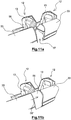
- the single wall 56 is able to slide between a “stowed” position in which the single wall 56 is superimposed at least partially with the fixed shell 33 of the “front” seat unit 12, and a “front” position. deployed ”in which the single wall 56 closes the transverse passage 37 between the“ front ”seat unit 12 and the“ rear ”seat unit 12, as shown in the figures. figures 10 , 11a and 11b .
- the single wall 56 is able to slide between a “stowed” position in which the single wall 56 is superimposed at least partially with the fixed shell 33 of the “rear” seat unit 12, and a “extended” position in which the single wall 56 closes the transverse passage 37 between the "front” seat unit 12 and the “rear” seat unit 12.
- the height of the single wall 56 can be adapted as needed.
- the height of the single wall 56 is less than that of the fixed shell 33, while, in the embodiment of figures 11a and 11b , the height of the single wall 56 is substantially equal to that of the fixed shell 33.
- the single wall 56 moves in a direction of translation D2 ', advantageously parallel to the longitudinal axis.
- the single wall 56 may be movable according to a rotational movement, in particular along a substantially horizontal axis, a substantially vertical axis, or an axis forming an angle with the longitudinal axis X1, or a combined movement comprising at least one translation. and at least one rotation.
- the first wall 41 in particular sliding, is able to close off the space located above the side cabinet 32.
- the second wall 43 is replaced by a blackout curtain 54 mounted on a support 55.
- the support 55 may be movable in translation and / or in rotation with respect to the “front” seat unit 12.
- the first wall 41 in particular sliding, is able to close off the space above the side cabinet 32.
- the second wall 43 is replaced by a curtain 58 mounted on a frame 59.
- the frame 59 may have a U-shape with two arms capable of sliding inside the “front” seat unit 12, in particular inside the intermediate wall 42.
- the curtain 54 closes all or part of the space between the intermediate wall 42 of the “front” seat unit 12 and the first wall 31.
- the first wall 41 in particular sliding, is able to close off the space located above the side cabinet 32.
- the second wall 43 is replaced by at least a first curtain 61, in particular a first curtain 61 and a second curtain 62.
- first curtain 61 and / or the second curtain 62 can be rolled up and is (are) installed in the “front” seat unit 12.
- the first curtain 61 makes it possible, when it is unrolled in the direction D2, to close at least part of the transverse passage 37, in particular a lower part of the transverse passage 37.
- the second curtain 52 makes it possible, when ' it is unwound in direction D2, to close at least part of the transverse passage 37 in particular an upper part of the transverse passage 37.
- first curtain 61 and / or the second curtain 62 in the “unrolled” state can be obtained by means of a hooking system 63 of the free end of the first curtain 61 and / or of the second curtain 62 on a wall of the "rear" seat unit 12.
- the attachment system 63 can be a system with hooks or magnets.
- first curtain 61 and / or the second curtain 62 could be made from an extensible material.
- the first curtain 61 can be installed in the “rear” seat unit 12.
- the second curtain 62 can be installed in the "rear” seat unit 12.
- the first curtain 61 and the second curtain 62 are located in separate seat units 12.
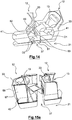
- the closure means 40 comprise at least two walls 67, 68, advantageously integral, movable with respect to one another.
- the walls 67, 68 are linked to one another according to at least one degree of freedom.
- the closure means 40 comprise at least a first wall 71 and a second wall 72, advantageously integral, movable with respect to one another.
- the first wall 71 and the second wall 72 are connected to one another according to at least one degree of freedom.
- the first wall 71 can be moved with the second wall 72 in a first direction of deployment D4, in particular parallel to the longitudinal axis X1 of the aircraft cabin 10 in order to close off at least part of the transverse passage 37, in particular a lower part of the transverse passage 37, as shown on the figure 16b .
- the first wall 71 can be moved in a horizontal translational movement.
- the second wall 72 is capable of being moved relative to the first wall 71 in a second direction of deployment D5, in particular a vertical direction, in order to close off at least one transverse passage part 37, in particular an upper part of the transverse passage 37 , as illustrated by figure 16c .
- the second wall 72 can be moved in a vertical translational movement.
- the present invention is not limited to a cabin arrangement in which each seat 13 is oriented towards the circulation corridor. 21 of the aircraft cabin 10. It also encompasses any arrangement of the aircraft cabin 10 in which there is a transverse passage 37 disposed between two seat units 12 arranged one behind the other along a longitudinal axis X1 of the aircraft cabin 10, allowing direct access to a taxiway 21.
- the invention can also be implemented with seats installed in other means of transport, such as, for example, seats for buses, trains or boats.
Landscapes
- Engineering & Computer Science (AREA)
- Aviation & Aerospace Engineering (AREA)
- Seats For Vehicles (AREA)
- Passenger Equipment (AREA)
- Chair Legs, Seat Parts, And Backrests (AREA)
Claims (14)
- Anordnung von Sitzen (11), insbesondere zum Einbau in eine Flugzeugkabine (10), umfassend:- mindestens eine "vordere" Sitzeinheit (12) und mindestens eine "hintere" Sitzeinheit (12), welche entlang einer Längsachse (X1) der Flugzeugkabine (10) hintereinander angeordnet sind, und jeweils mindestens einem Sitz (13) umfassen, der von einer "Sitzposition" zu einer "Liegeposition" übergehen kann,- einen Querdurchgang (37) zwischen der "vorderen" Sitzeinheit (12) und der "hinteren" Sitzeinheit (12), um den Zugang zu einem Gang (21) zu ermöglichen,wobei die Anordnung von Sitzen (11) bewegliche Schließmittel (40) umfasst, die den Querdurchgang (37) zumindest teilweise schließen können, wenn die Schließmittel (40) ausgefahrt sind,- wobei die Schließmittel (40) eine erste Wand (41) und eine zweite Wand (43) umfasst, die relativ zur Sitzeinheit (12) beweglich montiert sind,- wobei die erste Wand (41) in einer ersten Ausfahrrichtung (D1) zwischen• einer "verstauten" Position und• einer "ausgefahrenen" Position, in der die erste Wand (41) zumindest einen Teil des Querdurchgangs (37) zwischen der "vorderen" Sitzeinheit (12) und der "hinteren" Sitzeinheit (12) verschließt, gleiten kann,- wobei die zweite Wand (43) in einer zweiten Ausfahrrichtung (D2) zwischen• einer "verstauten" Position und• einer "ausgefahrenen" Position, in der die zweite Wand (43) zumindest einen Teil des Querdurchgangs (37) zwischen der "vorderen" Sitzeinheit (12) und der "hinteren" Sitzeinheit (12) verschließt, gleiten kann,- wobei sich die erste Wand (41) und die zweite Wand (43) beiderseits einer insbesondere durch einen Abschnitt einer festen Schale (33) der Sitzeinheit (12) gebildeten Zwischenwand (42) befinden,dadurch gekennzeichnet, dass die Zwischenwand (42) eine gewellte Form aufweist, die Vertiefungen (50) definiert, wobei zwei aufeinanderfolgende Vertiefungen (50) in zwei entgegengesetzten Richtungen offen sind, wobei Schienen (47) einer der Wände von der ersten oder der zweiten Wand (41, 43) in Vertiefungen (50) gelagert sind, die in Richtung des Sitzes (13) offen sind, und wobei Schienen (47) der anderen der Wände von der ersten und der zweiten Wand (41, 43) in Vertiefungen (50) gelagert sind, die in einer entgegengesetzten Richtung zum Sitz (13) offen sind.
- Anordnung von Sitzen (11) nach Anspruch 1, dadurch gekennzeichnet, dass der Sitz (13) einem Gang (21) der Flugzeugkabine (10) zugewandt ist.
- Anordnung von Sitzen (11) nach Anspruch 1 oder 2, dadurch gekennzeichnet, dass die Schließmittel (40) mindestens eine Gleitwand (41, 43) umfassen, die insbesondere starr oder flexibel ist.
- Anordnung von Sitzen (11) nach Anspruch 1, dadurch gekennzeichnet, dass die zweite Ausfahrrichtung (D2) der zweiten Wand (43) entgegengesetzt zur ersten Ausfahrrichtung (D1) der ersten Wand (41) ist.
- Anordnung von Sitzen (11) nach Anspruch 1, dadurch gekennzeichnet, dass die erste Wand (41) einstückig mit mindestens einem Schlitten (46) ist, der mit einer an der Zwischenwand (42) befestigten Schiene (47) zusammenwirkt und/oder dass die zweite Wand (43) einstückig mit mindestens einem Schlitten (46) ist, der mit einer an der Zwischenwand (42) befestigten Schiene (47) zusammenwirkt.
- Anordnung von Sitzen (11) nach einem der Ansprüche 1 bis 5, dadurch gekennzeichnet, dass sich eine Abdeckung (53) über mindestens eine entsprechende Schiene (47) erstreckt, um ein Einklemmen der Finger bei der Handhabung der ersten Wand (41) oder der zweiten Wand (43).
- Anordnung von Sitzen (11) nach einem der Ansprüche 1 bis 6, dadurch gekennzeichnet, dass ein unterer Teil der ersten Wand (41) und/oder der zweiten Wand (43) in einem Seitenschrank (32) der jeweils entsprechenden Sitzeinheit (12), wenn sich die erste Wand (41) und/oder die zweite Wand (43) in der verstauten Position befinden.
- Anordnung von Sitzen (11) nach Anspruch 1, dadurch gekennzeichnet, dass die erste Wand (41) und die zweite Wand (43) in einer translatorischen oder rotatorischen Bewegung oder einer kombinierten Bewegung aus mindestens einer Translation und mindestens einer Umdrehung bewegbar sind.
- Anordnung von Sitzen (11) nach einem der Ansprüche 1 bis 8, dadurch gekennzeichnet, dass die Schließmittel (40) mindestens einen Privatvorhang (54, 58, 61, 62) umfassen.
- Anordnung von Sitzen (11) nach Anspruch 9, dadurch gekennzeichnet, dass der Vorhang (54) zwischen• einer "verstauten" Position, bei der sich der Vorhang (54) innerhalb der "vorderen" Sitzeinheit (12), insbesondere innerhalb der festen Schale (33) der "vorderen" Sitzeinheit (12), befindet, und• einer "ausgefahrenen" Position, in der der Vorhang (54) zumindest einen Teil des Querdurchgangs (37) verschließt, an einem gelenkigen Träger (55) montiert ist.
- Anordnung von Sitzen (11) nach Anspruch 10, dadurch gekennzeichnet, dass der Träger (55) bezüglich der "vorderen" Sitzeinheit (12) translatorisch und/oder rotatorisch bewegbar ist, um von der "verstauten" Position in die "ausgefahrenen" Position umzugehen.
- Anordnung von Sitzen (11) nach Anspruch 9, dadurch gekennzeichnet, dass der Vorhang (58) an einem Rahmen (59) befestigt ist, welcher zwischen• einer "verstauten" Position, in der sich der Vorhang (58) innerhalb der "vorderen" Sitzeinheit (12), insbesondere innerhalb der festen Schale (33) der "vorderen" Sitzeinheit (12), befindet, und• einer "ausgefahrenen" Position, in der der Vorhang (58) zumindest einen Teil des Querdurchgangs (37) verschließt, gleiten kann.
- Anordnung von Sitzen (11) nach Anspruch 9, dadurch gekennzeichnet, dass die Schließmittel (40) einen ersten Vorhang (61) und/oder einen zweiten Vorhang (62) umfassen, welche insbesondere aufrollbar sind, und insbesondere in der "vorderen" Sitzeinheit (12) eingebaut sind, wobei der erste Vorhang (61) im abgerollten Zustand das Schließen zumindest eines Teils des Querdurchgangs (37), insbesondere eines unteren Teils des Querdurchgangs (37), ermöglicht und/oder der zweite Vorhang (62) im abgerollten Zustand das Schließen zumindest eines Teils des Querdurchgangs (37), insbesondere eines oberen Teils des Querdurchgangs (37), ermöglicht.
- Anordnung von Sitzen (11) nach einem der Ansprüche 1 bis 3, dadurch gekennzeichnet, dass die Schließmittel (40) mindestens zwei Wände (67, 68) umfassen, welche in mindestens einen Freiheitsgrad relativ zueinander bewegbar sind und in die gleiche Ausfahrrichtung oder in zwei verschiedene Richtungen ausgefahren werden.
Applications Claiming Priority (3)
| Application Number | Priority Date | Filing Date | Title |
|---|---|---|---|
| FR1657802A FR3055128A1 (fr) | 2016-08-17 | 2016-08-17 | Agencement de sieges permettant d'augmenter l'intimite des passagers, notamment d'un avion |
| FR1770491A FR3055117B1 (fr) | 2016-08-17 | 2017-05-15 | Arrangement de sieges, notamment d'un avion |
| PCT/EP2017/070854 WO2018033599A1 (fr) | 2016-08-17 | 2017-08-17 | Arrangement de sièges, notamment d'un avion |
Publications (2)
| Publication Number | Publication Date |
|---|---|
| EP3500489A1 EP3500489A1 (de) | 2019-06-26 |
| EP3500489B1 true EP3500489B1 (de) | 2021-12-15 |
Family
ID=59297162
Family Applications (1)
| Application Number | Title | Priority Date | Filing Date |
|---|---|---|---|
| EP17751779.4A Active EP3500489B1 (de) | 2016-08-17 | 2017-08-17 | Sitzanordnung, insbesondere für ein flugzeug |
Country Status (7)
| Country | Link |
|---|---|
| US (1) | US11312497B2 (de) |
| EP (1) | EP3500489B1 (de) |
| JP (1) | JP6978488B2 (de) |
| CN (1) | CN109803889B (de) |
| CA (1) | CA3033918C (de) |
| FR (2) | FR3055128A1 (de) |
| WO (1) | WO2018033599A1 (de) |
Families Citing this family (38)
| Publication number | Priority date | Publication date | Assignee | Title |
|---|---|---|---|---|
| US10421546B2 (en) * | 2017-04-04 | 2019-09-24 | Rockwell Collins, Inc. | Aircraft door and privacy panel assemblies |
| EP3606817B2 (de) | 2017-04-04 | 2023-12-13 | Safran Seats | Durchgangssperre zwischen nebeneinander angeordneten sitzen |
| FR3078946B1 (fr) | 2018-03-15 | 2022-03-04 | Zodiac Seats France | Arrangement de sieges, notamment d'un avion |
| EP3778398B1 (de) * | 2018-03-27 | 2025-01-08 | Jamco Corporation | Sitzeinheit für flugzeug |
| GB2572446A (en) | 2018-03-30 | 2019-10-02 | Acumen Design Ass Ltd | A passenger seating arrangement having access for disabled passengers |
| EP3546357B1 (de) * | 2018-03-30 | 2020-05-20 | Acumen Design Associates Ltd | Passagiersitzanordnung mit zugang für behinderte passagiere |
| US11623749B2 (en) | 2018-05-07 | 2023-04-11 | Safran Seats Usa Llc | Passenger seat privacy panel assembly |
| FR3081835B1 (fr) * | 2018-06-05 | 2021-04-09 | Zodiac Seats France | Arrangement de sieges, notamment d'un avion |
| US10549858B2 (en) | 2018-06-06 | 2020-02-04 | The Boeing Company | Seat pan for an aircraft |
| GB2577508B (en) * | 2018-09-26 | 2021-12-29 | Safran Seats Gb Ltd | Aircraft cabin |
| GB2579778B (en) * | 2018-12-12 | 2022-11-02 | Safran Seats Gb Ltd | A cover or harness for an aircraft passenger |
| FR3089952B1 (fr) * | 2018-12-18 | 2020-11-27 | Safran Seats | Dispositif de fermeture d'un passage entre deux unites de sieges |
| JP1659768S (de) * | 2019-03-29 | 2020-05-18 | ||
| FR3095617B1 (fr) * | 2019-04-30 | 2021-08-20 | Safran Seats | Ensemble de sieges, notamment pour un avion |
| US11180254B2 (en) * | 2019-05-24 | 2021-11-23 | AirGo Design Pte., Ltd. | Space-efficient flat-bed seating arrangement |
| FR3096655B1 (fr) * | 2019-05-29 | 2024-03-15 | Safran Seats | Arrangement de sieges pour classe economique premium |
| FR3098792B1 (fr) * | 2019-07-18 | 2021-06-25 | Safran Seats | Arrangements de sieges, notamment pour une cabine d'avion |
| GB2586273B (en) * | 2019-08-16 | 2023-04-12 | Safran Seats Gb Ltd | An aircraft cabin |
| GB2588122B (en) * | 2019-10-08 | 2023-11-22 | Safran Seats Gb Ltd | Aircraft passenger accommodation unit |
| GB2588121B (en) * | 2019-10-08 | 2023-12-20 | Safran Seats Gb Ltd | An aircraft passenger accommodation unit |
| CN114599583B (zh) * | 2019-10-29 | 2025-11-25 | 赛峰座椅英国有限公司 | 具有多滑轨推滑门的乘客座椅单元 |
| WO2021084249A1 (en) | 2019-10-29 | 2021-05-06 | Safran Seats GB Limited | An aircraft passenger accommodation unit |
| FR3105176B1 (fr) * | 2019-12-20 | 2022-07-22 | Safran Seats | Arrangement de sieges passagers |
| GB2590726B (en) | 2020-01-03 | 2024-04-03 | Safran Seats Gb Ltd | Aircraft passenger accommodation unit |
| US11299274B1 (en) * | 2020-01-31 | 2022-04-12 | B/E Aerospace, Inc. | Aircraft passenger compartment with an accessibility door |
| EP4153486B1 (de) * | 2020-05-18 | 2025-11-05 | Safran Seats USA LLC | Freihändig bedienbare vorrichtung für ein passagierfahrzeug |
| US11712494B2 (en) | 2020-05-26 | 2023-08-01 | Air-Clenz Systems, LLC | Enhanced exhaled air collector and air purification unit and system |
| CN112026814B (zh) * | 2020-08-31 | 2021-09-07 | 山东嘉泰交通设备有限公司 | 一种商务座椅及商务座椅的排列方法 |
| FR3114774A1 (fr) * | 2020-10-07 | 2022-04-08 | Speedinnov | Agencement intérieur de véhicule, véhicule et procédé d’utilisation d’un agencement interieur de véhicule associés |
| US12384543B2 (en) * | 2020-12-10 | 2025-08-12 | Safran Seats | Seat unit with a folding privacy shield |
| FR3125506B1 (fr) * | 2021-07-23 | 2024-09-13 | Safran Seats | Unité de siege munie d'une coque d'intimite escamotable |
| FR3128203B1 (fr) * | 2021-10-20 | 2023-09-01 | Safran Seats | Structure souple pour la création d'un espace de repos à l'intérieur d'une cabine d'aéronef |
| US12330791B2 (en) * | 2022-03-11 | 2025-06-17 | Adient Aerospace, Llc | Door assembly slide unit disengagement system |
| US12187434B2 (en) * | 2022-05-10 | 2025-01-07 | B/E Aerospace, Inc. | Persons with reduced mobility (PRM) suite access wall assembly |
| EP4543757A1 (de) * | 2022-06-22 | 2025-04-30 | Jamco America Inc., WA | Flexible flugzeugprivatsphärentür |
| FR3149303A1 (fr) * | 2023-06-05 | 2024-12-06 | Safran Seats | Ensemble de plateaux à surface extensible notamment pour un siège d'avion |
| US20250010995A1 (en) * | 2023-07-07 | 2025-01-09 | B/E Aerospace, Inc. | Business class suite with interior window and illuminated window shade |
| DE102024114823A1 (de) * | 2024-05-27 | 2025-11-27 | Airbus Operations Gmbh | Passagierabteil |
Family Cites Families (68)
| Publication number | Priority date | Publication date | Assignee | Title |
|---|---|---|---|---|
| US2947349A (en) * | 1958-04-10 | 1960-08-02 | Karl D Kryter | Seat and seating arrangement |
| US4597549A (en) * | 1984-09-28 | 1986-07-01 | Falcon Jet Corporation | Aircraft mid-cabin divider |
| US5214885A (en) * | 1989-04-11 | 1993-06-01 | Maas John C | Portable room divider |
| US5024398A (en) * | 1989-06-28 | 1991-06-18 | The Boeing Company | Office module for passenger aircraft |
| US5238282A (en) * | 1992-02-24 | 1993-08-24 | Watson Michael J | Vehicle interior partition |
| GB9425078D0 (en) * | 1994-12-13 | 1995-02-08 | British Airways Plc | A seating unit |
| SE506917C2 (sv) * | 1995-06-22 | 1998-03-02 | Hans Andersson | Persienn |
| US6152400A (en) * | 1997-09-10 | 2000-11-28 | The Boeing Company | Aircraft lower lobe sleeping compartment |
| ES2239461T3 (es) * | 1998-10-15 | 2005-09-16 | British Airways Plc | Una unidad de asiento. |
| US6378592B1 (en) * | 1999-03-16 | 2002-04-30 | Stephen G. Kimmet | Security system for a cubicle |
| US9428088B1 (en) * | 2008-01-23 | 2016-08-30 | Arjuna Indraeswaran Rajasingham | Vehicle occupant support |
| US6257523B1 (en) * | 1999-12-09 | 2001-07-10 | The Boeing Company | Foldable partition with integral door |
| CA2625280C (en) * | 2001-08-09 | 2010-08-03 | Virgin Atlantic Airways Limited | A seating system and a passenger accomodation unit for a vehicle |
| US6598539B2 (en) * | 2001-11-14 | 2003-07-29 | Westinghouse Air Brake Technologies Corporation | Power door operator having a drive member function as a hanger portion and rollers of a door panel hanger engaging the drive member for motion therealong |
| FR2839947B1 (fr) * | 2002-05-22 | 2004-11-26 | Airbus | Module individuel pour passager d'aeronef |
| FR2842498B1 (fr) * | 2002-07-19 | 2005-05-13 | Airbus | Module de cabine d'aeronef |
| FR2842497B1 (fr) * | 2002-07-19 | 2004-10-01 | Airbus | Module de cabine d'aeronef pour passagers |
| FR2843730B1 (fr) * | 2002-08-23 | 2005-07-08 | Airbus | Amenagement interieur d'une cabine d'aeronef |
| US10703483B1 (en) * | 2007-10-05 | 2020-07-07 | Arjuna Indraeswaran Rajasingham | Vehicle occupant support |
| US6823927B2 (en) * | 2003-03-05 | 2004-11-30 | Charles F. Steel | Pocket door with pivoting panel |
| US7014144B2 (en) * | 2003-07-22 | 2006-03-21 | Honeywell International, Inc. | Dual action inlet door and method for use thereof |
| WO2005080196A1 (en) * | 2004-02-20 | 2005-09-01 | Leadearn Investments Limited | An aircraft cabin |
| US7188806B2 (en) * | 2004-10-22 | 2007-03-13 | B E Aerospace, Inc. | Aircraft passenger accommodation unit with deployable bed |
| GB0425323D0 (en) * | 2004-11-17 | 2004-12-22 | Britax Aircraft Interiors Uk L | Aircraft seat |
| US7703718B2 (en) * | 2005-06-10 | 2010-04-27 | Airbus | Aircraft cabin arrangement and storage unit |
| US7721990B2 (en) * | 2005-07-29 | 2010-05-25 | Airbus Deutschland Gmbh | Passenger compartment |
| JP2009504510A (ja) * | 2005-08-22 | 2009-02-05 | ビー イー エアロスペイス,インク. | ラウンジ座席の配置構造 |
| SG168521A1 (en) * | 2005-12-23 | 2011-02-28 | British Airways Plc | Aircraft passenger seat |
| US7578470B2 (en) * | 2006-04-21 | 2009-08-25 | Be Aerospace, Inc. | Passenger seating arrangement |
| GB2438162A (en) * | 2006-05-19 | 2007-11-21 | British Airways Plc | Reclining aircraft seat convertible into bed |
| FR2904805B1 (fr) * | 2006-08-10 | 2009-06-26 | Airbus Sas | Sous-ensemble de cabine d'aeronef et aeronef comportant un tel sous-ensemble |
| GB0706775D0 (en) * | 2007-04-05 | 2007-05-16 | Premium Aircraft Interiors Uk | Aircraft seat |
| US8245970B2 (en) * | 2008-08-11 | 2012-08-21 | American Airlines, Inc. | Array of aircraft seats |
| US8348195B2 (en) * | 2008-08-14 | 2013-01-08 | American Airlines, Inc. | Array of aircraft seats |
| US8196864B2 (en) * | 2008-09-05 | 2012-06-12 | Weber Aircraft Llc | Seating arrangements particularly for passenger aircraft |
| FR2935684B1 (fr) * | 2008-09-10 | 2011-05-13 | Airbus | Systeme de sieges pour passager integrant un meuble multi-fonctionnel, et aeronef comprenant un tel systeme |
| GB2469180B8 (en) * | 2009-03-23 | 2016-06-08 | Air New Zealand Ltd | Vehicle seating arrangement |
| USD649793S1 (en) * | 2009-12-10 | 2011-12-06 | Air New Zealand Limited | Aircraft seat |
| DE102010019192A1 (de) * | 2010-05-04 | 2011-11-10 | Recaro Aircraft Seating Gmbh & Co. Kg | Sitzanordnung einer Passagierkabine |
| CA2814622C (en) * | 2010-10-15 | 2019-08-27 | Bombardier Inc. | Aircraft interior configuration |
| US8662447B2 (en) * | 2011-06-17 | 2014-03-04 | Be Aerospace, Inc. | Flexible-usage travel suite |
| FR2978190B1 (fr) * | 2011-07-22 | 2013-09-13 | Dassault Aviat | Mecanisme d'articulation frangible pour une cloison de plateforme, cloison, ensemble et procede associes |
| EP2825458B1 (de) * | 2012-03-14 | 2018-11-28 | B/E Aerospace Inc. | Flugzeugpassagiersuite mit kombinationsbett |
| DE102012005980A1 (de) * | 2012-03-23 | 2013-09-26 | Airbus Operations Gmbh | Adapter zum Befestigen eines Sitzes in einer Kabine eines Fahrzeugs, Sitz für eine Kabine eines Fahrzeugs, Fahrzeug mit einer Kabine und einem Sitz |
| US9469405B2 (en) * | 2012-08-01 | 2016-10-18 | B/E Aerospace, Inc. | Passenger suite seating arrangement with moveable video monitor |
| US9266614B2 (en) * | 2012-08-01 | 2016-02-23 | B/E Aerospace, Inc. | Passenger suite seating arrangement with moveable video monitor |
| US9308997B2 (en) * | 2012-09-17 | 2016-04-12 | The Boeing Company | Lavatory reconfiguration system |
| GB201217319D0 (en) * | 2012-09-27 | 2012-11-14 | Acumen Design Associates Ltd | Aircraft passenger seating arrangement |
| US9889936B2 (en) * | 2012-10-30 | 2018-02-13 | The Boeing Company | Curved seating layout |
| US9045231B2 (en) * | 2012-11-05 | 2015-06-02 | C&D Zodiac, Inc. | Wheelchair accessible lavatory |
| EP2948372B1 (de) * | 2013-01-23 | 2016-08-24 | Zodiac Seats France | Bettverlängerung |
| AU2014240780A1 (en) * | 2013-03-28 | 2015-11-12 | Etihad Airways | Seating array for an aircraft cabin |
| US9321533B2 (en) * | 2013-05-29 | 2016-04-26 | The Boeing Company | Aircraft passageway storage units |
| US9688407B2 (en) * | 2013-10-03 | 2017-06-27 | The Boeing Company | Modular lavatory system |
| WO2015059676A1 (en) * | 2013-10-24 | 2015-04-30 | Zodiac Seats Uk Limited | Arrangement of seat units in a vehicle cabin |
| CA2927996A1 (en) * | 2013-11-12 | 2015-05-21 | B/E Aerospace, Inc. | Aircraft seat with taxi, takeoff and landing lie flat position capability |
| US10556689B2 (en) * | 2013-12-03 | 2020-02-11 | Butterfly Flexible Seating Solutions Limited | Convertible seating unit |
| US9428259B2 (en) * | 2014-03-27 | 2016-08-30 | C&D Zodiac, Inc. | Bi-fold door module |
| WO2015148813A1 (en) * | 2014-03-27 | 2015-10-01 | C&D Zodiac, Inc. | Bi-fold door module |
| EP2927124B1 (de) * | 2014-04-04 | 2020-10-28 | Airbus Operations GmbH | Faltbare Trennvorrichtung für eine Flugzeugkabine |
| US9409648B2 (en) * | 2014-05-15 | 2016-08-09 | The Boeing Company | Seating arrangement and method |
| US9976336B2 (en) * | 2014-07-11 | 2018-05-22 | B/E Aerospace, Inc. | Telescoping aircraft panel door |
| US9834977B2 (en) * | 2014-11-05 | 2017-12-05 | Jakes Associates, Inc. | Streetcar door system |
| US9622570B1 (en) * | 2015-02-13 | 2017-04-18 | Steelcase Inc. | Personal workspace assembly |
| US9802704B2 (en) * | 2015-03-13 | 2017-10-31 | The Boeing Company | Folding galley unit |
| FR3036098B1 (fr) * | 2015-05-12 | 2017-05-12 | Airbus Operations Sas | Dispositif d'acces a paroi pliante permettant la communication securisee entre au moins deux zones d'une enceinte |
| EP3541654B1 (de) * | 2016-11-15 | 2023-08-16 | Safran Seats USA LLC | Notausgangslösungen für mini-suiten |
| US10988055B2 (en) * | 2017-03-17 | 2021-04-27 | Safran Seats Usa Llc | Passenger seat with movable backrest portion |
-
2016
- 2016-08-17 FR FR1657802A patent/FR3055128A1/fr active Pending
-
2017
- 2017-05-15 FR FR1770491A patent/FR3055117B1/fr active Active
- 2017-08-17 EP EP17751779.4A patent/EP3500489B1/de active Active
- 2017-08-17 JP JP2019508829A patent/JP6978488B2/ja active Active
- 2017-08-17 CN CN201780061925.9A patent/CN109803889B/zh active Active
- 2017-08-17 WO PCT/EP2017/070854 patent/WO2018033599A1/fr not_active Ceased
- 2017-08-17 CA CA3033918A patent/CA3033918C/fr active Active
- 2017-08-17 US US16/325,778 patent/US11312497B2/en active Active
Non-Patent Citations (1)
| Title |
|---|
| None * |
Also Published As
| Publication number | Publication date |
|---|---|
| CN109803889A (zh) | 2019-05-24 |
| FR3055128A1 (fr) | 2018-02-23 |
| EP3500489A1 (de) | 2019-06-26 |
| FR3055117A1 (fr) | 2018-02-23 |
| CN109803889B (zh) | 2022-07-12 |
| WO2018033599A1 (fr) | 2018-02-22 |
| JP6978488B2 (ja) | 2021-12-08 |
| JP2019526485A (ja) | 2019-09-19 |
| FR3055117B1 (fr) | 2021-02-19 |
| CA3033918A1 (fr) | 2018-02-22 |
| US20190210733A1 (en) | 2019-07-11 |
| US11312497B2 (en) | 2022-04-26 |
| CA3033918C (fr) | 2023-08-08 |
Similar Documents
| Publication | Publication Date | Title |
|---|---|---|
| CA3033918C (fr) | Arrangement de sieges, notamment d'un avion | |
| EP3765367B1 (de) | Sitzanordnung, insbesondere von einem flugzeug | |
| EP3606817B1 (de) | Durchgangssperre zwischen nebeneinander angeordneten sitzen | |
| EP3802321B1 (de) | Vorrichtung zum schliessen eines raumes in einem flugzeug | |
| EP3554947B1 (de) | Anordnung aus einzelnen sitzen für passagiere eines flugzeugs | |
| CA2779673C (fr) | Siege convertible en couchette | |
| EP3601044B1 (de) | Individuelle flugzeugpassagiere sitzanordnung mit bildschirmstützen, die eine trennwand bilden | |
| EP2219945B1 (de) | Optimiertes flugzeugkabinenlayout | |
| EP2303692B1 (de) | Sitzmodul für einen flugzeugpassagier | |
| EP1523442B1 (de) | Flugzeugkabinenmodul | |
| EP4077133B1 (de) | Passgiersitzanordnung | |
| EP4259523B1 (de) | Sitzeinheit mit faltbarem sichtschutzschild | |
| EP3999421B1 (de) | Sitzanordnungen, insbesondere für eine flugzeugkabine | |
| WO2020239579A1 (fr) | Arrangement de sièges pour classe economique premium | |
| WO2017168105A1 (fr) | Siège convertible en couchage elargi | |
| EP3962812B1 (de) | Sitzgruppe, insbesondere für flugzeuge | |
| FR3137662A1 (fr) | Unité de siège munie d'une coque d'intimité escamotable | |
| FR3125506A1 (fr) | Unité de siege munie d'une coque d'intimite escamotable | |
| FR3157352A1 (fr) | Élément d'appui pour un siège d'aéronef facilitant l’installation d’une personne à mobilité réduite | |
| FR3116808A1 (fr) | Dispositif de separation amovible muni d'une paroi a effet visuel, notamment pour une cabine d'avion | |
| FR3129138A1 (fr) | Dispositif de fermeture amovible d'un espace, notamment pour une cabine d'avion | |
| EP4185530A1 (de) | Suite mit verbesserter anordnung, insbesondere für eine flugzeugkabine |
Legal Events
| Date | Code | Title | Description |
|---|---|---|---|
| STAA | Information on the status of an ep patent application or granted ep patent |
Free format text: STATUS: UNKNOWN |
|
| STAA | Information on the status of an ep patent application or granted ep patent |
Free format text: STATUS: THE INTERNATIONAL PUBLICATION HAS BEEN MADE |
|
| PUAI | Public reference made under article 153(3) epc to a published international application that has entered the european phase |
Free format text: ORIGINAL CODE: 0009012 |
|
| STAA | Information on the status of an ep patent application or granted ep patent |
Free format text: STATUS: REQUEST FOR EXAMINATION WAS MADE |
|
| 17P | Request for examination filed |
Effective date: 20190205 |
|
| AK | Designated contracting states |
Kind code of ref document: A1 Designated state(s): AL AT BE BG CH CY CZ DE DK EE ES FI FR GB GR HR HU IE IS IT LI LT LU LV MC MK MT NL NO PL PT RO RS SE SI SK SM TR |
|
| AX | Request for extension of the european patent |
Extension state: BA ME |
|
| DAV | Request for validation of the european patent (deleted) | ||
| DAX | Request for extension of the european patent (deleted) | ||
| STAA | Information on the status of an ep patent application or granted ep patent |
Free format text: STATUS: EXAMINATION IS IN PROGRESS |
|
| 17Q | First examination report despatched |
Effective date: 20201020 |
|
| GRAP | Despatch of communication of intention to grant a patent |
Free format text: ORIGINAL CODE: EPIDOSNIGR1 |
|
| STAA | Information on the status of an ep patent application or granted ep patent |
Free format text: STATUS: GRANT OF PATENT IS INTENDED |
|
| INTG | Intention to grant announced |
Effective date: 20210715 |
|
| GRAS | Grant fee paid |
Free format text: ORIGINAL CODE: EPIDOSNIGR3 |
|
| GRAA | (expected) grant |
Free format text: ORIGINAL CODE: 0009210 |
|
| STAA | Information on the status of an ep patent application or granted ep patent |
Free format text: STATUS: THE PATENT HAS BEEN GRANTED |
|
| AK | Designated contracting states |
Kind code of ref document: B1 Designated state(s): AL AT BE BG CH CY CZ DE DK EE ES FI FR GB GR HR HU IE IS IT LI LT LU LV MC MK MT NL NO PL PT RO RS SE SI SK SM TR |
|
| REG | Reference to a national code |
Ref country code: GB Ref legal event code: FG4D Free format text: NOT ENGLISH Ref country code: CH Ref legal event code: EP |
|
| REG | Reference to a national code |
Ref country code: IE Ref legal event code: FG4D Free format text: LANGUAGE OF EP DOCUMENT: FRENCH Ref country code: DE Ref legal event code: R096 Ref document number: 602017050959 Country of ref document: DE |
|
| REG | Reference to a national code |
Ref country code: AT Ref legal event code: REF Ref document number: 1455325 Country of ref document: AT Kind code of ref document: T Effective date: 20220115 |
|
| REG | Reference to a national code |
Ref country code: LT Ref legal event code: MG9D |
|
| REG | Reference to a national code |
Ref country code: NL Ref legal event code: MP Effective date: 20211215 |
|
| PG25 | Lapsed in a contracting state [announced via postgrant information from national office to epo] |
Ref country code: RS Free format text: LAPSE BECAUSE OF FAILURE TO SUBMIT A TRANSLATION OF THE DESCRIPTION OR TO PAY THE FEE WITHIN THE PRESCRIBED TIME-LIMIT Effective date: 20211215 Ref country code: LT Free format text: LAPSE BECAUSE OF FAILURE TO SUBMIT A TRANSLATION OF THE DESCRIPTION OR TO PAY THE FEE WITHIN THE PRESCRIBED TIME-LIMIT Effective date: 20211215 Ref country code: FI Free format text: LAPSE BECAUSE OF FAILURE TO SUBMIT A TRANSLATION OF THE DESCRIPTION OR TO PAY THE FEE WITHIN THE PRESCRIBED TIME-LIMIT Effective date: 20211215 Ref country code: BG Free format text: LAPSE BECAUSE OF FAILURE TO SUBMIT A TRANSLATION OF THE DESCRIPTION OR TO PAY THE FEE WITHIN THE PRESCRIBED TIME-LIMIT Effective date: 20220315 |
|
| REG | Reference to a national code |
Ref country code: AT Ref legal event code: MK05 Ref document number: 1455325 Country of ref document: AT Kind code of ref document: T Effective date: 20211215 |
|
| PG25 | Lapsed in a contracting state [announced via postgrant information from national office to epo] |
Ref country code: SE Free format text: LAPSE BECAUSE OF FAILURE TO SUBMIT A TRANSLATION OF THE DESCRIPTION OR TO PAY THE FEE WITHIN THE PRESCRIBED TIME-LIMIT Effective date: 20211215 Ref country code: NO Free format text: LAPSE BECAUSE OF FAILURE TO SUBMIT A TRANSLATION OF THE DESCRIPTION OR TO PAY THE FEE WITHIN THE PRESCRIBED TIME-LIMIT Effective date: 20220315 Ref country code: LV Free format text: LAPSE BECAUSE OF FAILURE TO SUBMIT A TRANSLATION OF THE DESCRIPTION OR TO PAY THE FEE WITHIN THE PRESCRIBED TIME-LIMIT Effective date: 20211215 Ref country code: HR Free format text: LAPSE BECAUSE OF FAILURE TO SUBMIT A TRANSLATION OF THE DESCRIPTION OR TO PAY THE FEE WITHIN THE PRESCRIBED TIME-LIMIT Effective date: 20211215 Ref country code: GR Free format text: LAPSE BECAUSE OF FAILURE TO SUBMIT A TRANSLATION OF THE DESCRIPTION OR TO PAY THE FEE WITHIN THE PRESCRIBED TIME-LIMIT Effective date: 20220316 |
|
| PG25 | Lapsed in a contracting state [announced via postgrant information from national office to epo] |
Ref country code: NL Free format text: LAPSE BECAUSE OF FAILURE TO SUBMIT A TRANSLATION OF THE DESCRIPTION OR TO PAY THE FEE WITHIN THE PRESCRIBED TIME-LIMIT Effective date: 20211215 |
|
| PG25 | Lapsed in a contracting state [announced via postgrant information from national office to epo] |
Ref country code: SM Free format text: LAPSE BECAUSE OF FAILURE TO SUBMIT A TRANSLATION OF THE DESCRIPTION OR TO PAY THE FEE WITHIN THE PRESCRIBED TIME-LIMIT Effective date: 20211215 Ref country code: SK Free format text: LAPSE BECAUSE OF FAILURE TO SUBMIT A TRANSLATION OF THE DESCRIPTION OR TO PAY THE FEE WITHIN THE PRESCRIBED TIME-LIMIT Effective date: 20211215 Ref country code: RO Free format text: LAPSE BECAUSE OF FAILURE TO SUBMIT A TRANSLATION OF THE DESCRIPTION OR TO PAY THE FEE WITHIN THE PRESCRIBED TIME-LIMIT Effective date: 20211215 Ref country code: PT Free format text: LAPSE BECAUSE OF FAILURE TO SUBMIT A TRANSLATION OF THE DESCRIPTION OR TO PAY THE FEE WITHIN THE PRESCRIBED TIME-LIMIT Effective date: 20220418 Ref country code: ES Free format text: LAPSE BECAUSE OF FAILURE TO SUBMIT A TRANSLATION OF THE DESCRIPTION OR TO PAY THE FEE WITHIN THE PRESCRIBED TIME-LIMIT Effective date: 20211215 Ref country code: EE Free format text: LAPSE BECAUSE OF FAILURE TO SUBMIT A TRANSLATION OF THE DESCRIPTION OR TO PAY THE FEE WITHIN THE PRESCRIBED TIME-LIMIT Effective date: 20211215 Ref country code: CZ Free format text: LAPSE BECAUSE OF FAILURE TO SUBMIT A TRANSLATION OF THE DESCRIPTION OR TO PAY THE FEE WITHIN THE PRESCRIBED TIME-LIMIT Effective date: 20211215 |
|
| PG25 | Lapsed in a contracting state [announced via postgrant information from national office to epo] |
Ref country code: PL Free format text: LAPSE BECAUSE OF FAILURE TO SUBMIT A TRANSLATION OF THE DESCRIPTION OR TO PAY THE FEE WITHIN THE PRESCRIBED TIME-LIMIT Effective date: 20211215 Ref country code: AT Free format text: LAPSE BECAUSE OF FAILURE TO SUBMIT A TRANSLATION OF THE DESCRIPTION OR TO PAY THE FEE WITHIN THE PRESCRIBED TIME-LIMIT Effective date: 20211215 |
|
| REG | Reference to a national code |
Ref country code: DE Ref legal event code: R097 Ref document number: 602017050959 Country of ref document: DE |
|
| PG25 | Lapsed in a contracting state [announced via postgrant information from national office to epo] |
Ref country code: IS Free format text: LAPSE BECAUSE OF FAILURE TO SUBMIT A TRANSLATION OF THE DESCRIPTION OR TO PAY THE FEE WITHIN THE PRESCRIBED TIME-LIMIT Effective date: 20220415 |
|
| PLBE | No opposition filed within time limit |
Free format text: ORIGINAL CODE: 0009261 |
|
| STAA | Information on the status of an ep patent application or granted ep patent |
Free format text: STATUS: NO OPPOSITION FILED WITHIN TIME LIMIT |
|
| PG25 | Lapsed in a contracting state [announced via postgrant information from national office to epo] |
Ref country code: DK Free format text: LAPSE BECAUSE OF FAILURE TO SUBMIT A TRANSLATION OF THE DESCRIPTION OR TO PAY THE FEE WITHIN THE PRESCRIBED TIME-LIMIT Effective date: 20211215 Ref country code: AL Free format text: LAPSE BECAUSE OF FAILURE TO SUBMIT A TRANSLATION OF THE DESCRIPTION OR TO PAY THE FEE WITHIN THE PRESCRIBED TIME-LIMIT Effective date: 20211215 |
|
| 26N | No opposition filed |
Effective date: 20220916 |
|
| PG25 | Lapsed in a contracting state [announced via postgrant information from national office to epo] |
Ref country code: SI Free format text: LAPSE BECAUSE OF FAILURE TO SUBMIT A TRANSLATION OF THE DESCRIPTION OR TO PAY THE FEE WITHIN THE PRESCRIBED TIME-LIMIT Effective date: 20211215 |
|
| PG25 | Lapsed in a contracting state [announced via postgrant information from national office to epo] |
Ref country code: MC Free format text: LAPSE BECAUSE OF FAILURE TO SUBMIT A TRANSLATION OF THE DESCRIPTION OR TO PAY THE FEE WITHIN THE PRESCRIBED TIME-LIMIT Effective date: 20211215 |
|
| REG | Reference to a national code |
Ref country code: CH Ref legal event code: PL |
|
| PG25 | Lapsed in a contracting state [announced via postgrant information from national office to epo] |
Ref country code: LU Free format text: LAPSE BECAUSE OF NON-PAYMENT OF DUE FEES Effective date: 20220817 Ref country code: LI Free format text: LAPSE BECAUSE OF NON-PAYMENT OF DUE FEES Effective date: 20220831 Ref country code: CH Free format text: LAPSE BECAUSE OF NON-PAYMENT OF DUE FEES Effective date: 20220831 |
|
| REG | Reference to a national code |
Ref country code: BE Ref legal event code: MM Effective date: 20220831 |
|
| PG25 | Lapsed in a contracting state [announced via postgrant information from national office to epo] |
Ref country code: IT Free format text: LAPSE BECAUSE OF FAILURE TO SUBMIT A TRANSLATION OF THE DESCRIPTION OR TO PAY THE FEE WITHIN THE PRESCRIBED TIME-LIMIT Effective date: 20211215 |
|
| PG25 | Lapsed in a contracting state [announced via postgrant information from national office to epo] |
Ref country code: IE Free format text: LAPSE BECAUSE OF NON-PAYMENT OF DUE FEES Effective date: 20220817 |
|
| PG25 | Lapsed in a contracting state [announced via postgrant information from national office to epo] |
Ref country code: BE Free format text: LAPSE BECAUSE OF NON-PAYMENT OF DUE FEES Effective date: 20220831 |
|
| PG25 | Lapsed in a contracting state [announced via postgrant information from national office to epo] |
Ref country code: HU Free format text: LAPSE BECAUSE OF FAILURE TO SUBMIT A TRANSLATION OF THE DESCRIPTION OR TO PAY THE FEE WITHIN THE PRESCRIBED TIME-LIMIT; INVALID AB INITIO Effective date: 20170817 |
|
| PG25 | Lapsed in a contracting state [announced via postgrant information from national office to epo] |
Ref country code: CY Free format text: LAPSE BECAUSE OF FAILURE TO SUBMIT A TRANSLATION OF THE DESCRIPTION OR TO PAY THE FEE WITHIN THE PRESCRIBED TIME-LIMIT Effective date: 20211215 |
|
| PG25 | Lapsed in a contracting state [announced via postgrant information from national office to epo] |
Ref country code: MK Free format text: LAPSE BECAUSE OF FAILURE TO SUBMIT A TRANSLATION OF THE DESCRIPTION OR TO PAY THE FEE WITHIN THE PRESCRIBED TIME-LIMIT Effective date: 20211215 |
|
| PG25 | Lapsed in a contracting state [announced via postgrant information from national office to epo] |
Ref country code: TR Free format text: LAPSE BECAUSE OF FAILURE TO SUBMIT A TRANSLATION OF THE DESCRIPTION OR TO PAY THE FEE WITHIN THE PRESCRIBED TIME-LIMIT Effective date: 20211215 |
|
| PG25 | Lapsed in a contracting state [announced via postgrant information from national office to epo] |
Ref country code: MT Free format text: LAPSE BECAUSE OF FAILURE TO SUBMIT A TRANSLATION OF THE DESCRIPTION OR TO PAY THE FEE WITHIN THE PRESCRIBED TIME-LIMIT Effective date: 20211215 |
|
| PGFP | Annual fee paid to national office [announced via postgrant information from national office to epo] |
Ref country code: DE Payment date: 20250819 Year of fee payment: 9 |
|
| PGFP | Annual fee paid to national office [announced via postgrant information from national office to epo] |
Ref country code: GB Payment date: 20250825 Year of fee payment: 9 |
|
| PGFP | Annual fee paid to national office [announced via postgrant information from national office to epo] |
Ref country code: FR Payment date: 20250827 Year of fee payment: 9 |