EP3499499B1 - Anti-resonanz-platte und verfahren zur herstellung davon - Google Patents
Anti-resonanz-platte und verfahren zur herstellung davon Download PDFInfo
- Publication number
- EP3499499B1 EP3499499B1 EP18200803.7A EP18200803A EP3499499B1 EP 3499499 B1 EP3499499 B1 EP 3499499B1 EP 18200803 A EP18200803 A EP 18200803A EP 3499499 B1 EP3499499 B1 EP 3499499B1
- Authority
- EP
- European Patent Office
- Prior art keywords
- stiffener
- resonant
- base panel
- panel
- members
- Prior art date
- Legal status (The legal status is an assumption and is not a legal conclusion. Google has not performed a legal analysis and makes no representation as to the accuracy of the status listed.)
- Active
Links
Images


Classifications
-
- B—PERFORMING OPERATIONS; TRANSPORTING
- B64—AIRCRAFT; AVIATION; COSMONAUTICS
- B64C—AEROPLANES; HELICOPTERS
- B64C1/00—Fuselages; Constructional features common to fuselages, wings, stabilising surfaces or the like
- B64C1/06—Frames; Stringers; Longerons ; Fuselage sections
- B64C1/12—Construction or attachment of skin panels
-
- B—PERFORMING OPERATIONS; TRANSPORTING
- B32—LAYERED PRODUCTS
- B32B—LAYERED PRODUCTS, i.e. PRODUCTS BUILT-UP OF STRATA OF FLAT OR NON-FLAT, e.g. CELLULAR OR HONEYCOMB, FORM
- B32B27/00—Layered products comprising a layer of synthetic resin
- B32B27/12—Layered products comprising a layer of synthetic resin next to a fibrous or filamentary layer
-
- B—PERFORMING OPERATIONS; TRANSPORTING
- B32—LAYERED PRODUCTS
- B32B—LAYERED PRODUCTS, i.e. PRODUCTS BUILT-UP OF STRATA OF FLAT OR NON-FLAT, e.g. CELLULAR OR HONEYCOMB, FORM
- B32B3/00—Layered products comprising a layer with external or internal discontinuities or unevennesses, or a layer of non-planar shape; Layered products comprising a layer having particular features of form
- B32B3/02—Layered products comprising a layer with external or internal discontinuities or unevennesses, or a layer of non-planar shape; Layered products comprising a layer having particular features of form characterised by features of form at particular places, e.g. in edge regions
- B32B3/08—Layered products comprising a layer with external or internal discontinuities or unevennesses, or a layer of non-planar shape; Layered products comprising a layer having particular features of form characterised by features of form at particular places, e.g. in edge regions characterised by added members at particular parts
-
- B—PERFORMING OPERATIONS; TRANSPORTING
- B32—LAYERED PRODUCTS
- B32B—LAYERED PRODUCTS, i.e. PRODUCTS BUILT-UP OF STRATA OF FLAT OR NON-FLAT, e.g. CELLULAR OR HONEYCOMB, FORM
- B32B3/00—Layered products comprising a layer with external or internal discontinuities or unevennesses, or a layer of non-planar shape; Layered products comprising a layer having particular features of form
- B32B3/10—Layered products comprising a layer with external or internal discontinuities or unevennesses, or a layer of non-planar shape; Layered products comprising a layer having particular features of form characterised by a discontinuous layer, i.e. formed of separate pieces of material
- B32B3/12—Layered products comprising a layer with external or internal discontinuities or unevennesses, or a layer of non-planar shape; Layered products comprising a layer having particular features of form characterised by a discontinuous layer, i.e. formed of separate pieces of material characterised by a layer of regularly- arranged cells, e.g. a honeycomb structure
-
- B—PERFORMING OPERATIONS; TRANSPORTING
- B60—VEHICLES IN GENERAL
- B60R—VEHICLES, VEHICLE FITTINGS, OR VEHICLE PARTS, NOT OTHERWISE PROVIDED FOR
- B60R13/00—Elements for body-finishing, identifying, or decorating; Arrangements or adaptations for advertising purposes
- B60R13/08—Insulating elements, e.g. for sound insulation
- B60R13/0815—Acoustic or thermal insulation of passenger compartments
-
- B—PERFORMING OPERATIONS; TRANSPORTING
- B64—AIRCRAFT; AVIATION; COSMONAUTICS
- B64C—AEROPLANES; HELICOPTERS
- B64C1/00—Fuselages; Constructional features common to fuselages, wings, stabilising surfaces or the like
- B64C1/06—Frames; Stringers; Longerons ; Fuselage sections
- B64C1/10—Bulkheads
-
- B—PERFORMING OPERATIONS; TRANSPORTING
- B64—AIRCRAFT; AVIATION; COSMONAUTICS
- B64C—AEROPLANES; HELICOPTERS
- B64C1/00—Fuselages; Constructional features common to fuselages, wings, stabilising surfaces or the like
- B64C1/40—Sound or heat insulation, e.g. using insulation blankets
-
- B—PERFORMING OPERATIONS; TRANSPORTING
- B64—AIRCRAFT; AVIATION; COSMONAUTICS
- B64F—GROUND OR AIRCRAFT-CARRIER-DECK INSTALLATIONS SPECIALLY ADAPTED FOR USE IN CONNECTION WITH AIRCRAFT; DESIGNING, MANUFACTURING, ASSEMBLING, CLEANING, MAINTAINING OR REPAIRING AIRCRAFT, NOT OTHERWISE PROVIDED FOR; HANDLING, TRANSPORTING, TESTING OR INSPECTING AIRCRAFT COMPONENTS, NOT OTHERWISE PROVIDED FOR
- B64F5/00—Designing, manufacturing, assembling, cleaning, maintaining or repairing aircraft, not otherwise provided for; Handling, transporting, testing or inspecting aircraft components, not otherwise provided for
- B64F5/10—Manufacturing or assembling aircraft, e.g. jigs therefor
-
- G—PHYSICS
- G10—MUSICAL INSTRUMENTS; ACOUSTICS
- G10K—SOUND-PRODUCING DEVICES; METHODS OR DEVICES FOR PROTECTING AGAINST, OR FOR DAMPING, NOISE OR OTHER ACOUSTIC WAVES IN GENERAL; ACOUSTICS NOT OTHERWISE PROVIDED FOR
- G10K11/00—Methods or devices for transmitting, conducting or directing sound in general; Methods or devices for protecting against, or for damping, noise or other acoustic waves in general
- G10K11/16—Methods or devices for protecting against, or for damping, noise or other acoustic waves in general
- G10K11/162—Selection of materials
- G10K11/168—Plural layers of different materials, e.g. sandwiches
-
- B—PERFORMING OPERATIONS; TRANSPORTING
- B60—VEHICLES IN GENERAL
- B60Y—INDEXING SCHEME RELATING TO ASPECTS CROSS-CUTTING VEHICLE TECHNOLOGY
- B60Y2306/00—Other features of vehicle sub-units
- B60Y2306/09—Reducing noise
-
- G—PHYSICS
- G10—MUSICAL INSTRUMENTS; ACOUSTICS
- G10K—SOUND-PRODUCING DEVICES; METHODS OR DEVICES FOR PROTECTING AGAINST, OR FOR DAMPING, NOISE OR OTHER ACOUSTIC WAVES IN GENERAL; ACOUSTICS NOT OTHERWISE PROVIDED FOR
- G10K11/00—Methods or devices for transmitting, conducting or directing sound in general; Methods or devices for protecting against, or for damping, noise or other acoustic waves in general
- G10K11/16—Methods or devices for protecting against, or for damping, noise or other acoustic waves in general
- G10K11/172—Methods or devices for protecting against, or for damping, noise or other acoustic waves in general using resonance effects
Definitions
- Example embodiments of the present disclosure relate generally to noise insulating materials and, more particularly, to methods and systems providing noise insulation using a panel.
- JP 2001-233249 A in accordance with its abstract, states a recyclable sound insulating material for a vehicle.
- a raw fabric mat M is formed when a fiber material prepared by mixing together a long-fiber recyclable PET and cotton with shape maintaining characteristic and impregnated with a phenol resin.
- a sound absorbing base material is formed by thermocompression molding the raw fiber mat M that is suitable for an engine room.
- US 2017/069304 A1 in accordance with its abstract, states a transportation vehicle part including: a patch member constructed of a plate-like metal patch panel, and a vibration attenuating resin layer provided along a surface of the patch panel; and a metal base plate closely adhered with the vibration attenuating resin layer of the patch member and affixed with the patch member.
- the patch panel is produced via a rolling step. An acute angle between a longitudinal direction and a rolling direction of the patch panel is 30 to 70 degrees.
- US 8869933 B1 in accordance with its abstract, states an acoustic barrier structure including a support structure that defines a plurality of cells, a weight attached to the support structure, and at least one resonant membrane covering one of the plurality of cells.
- the at least one resonant membrane can comprise at least one weight.
- US 2013/087407 A1 in accordance with its abstract, states a membrane containing a first weight disposed at a center portion of the membrane, and a first hinge structure disposed away from the center portion of the membrane.
- US 4778028 A in accordance with its abstract, states a light viscoelastic damping structure having a plurality of damping strips widely separated on the surface of a lightweight panel. The strips may be arranged parallel or at right angles to each other.
- Each damping strip includes a viscoelastic damping layer, a first honeycomb structure having opposing face sheets and attached to one surface of the damping layer, and a second honeycomb structure having face sheets on opposing sides thereof attached to the damping layer and to the panel.
- US 2014/326536 A1 in accordance with its abstract, states an acoustic attenuation panel including a resistive skin having acoustic holes, a solid skin and an acoustic structure.
- the acoustic structure includes a sound-absorbing material and is arranged between the resistive skin and the solid skin.
- the solid skin is structural and forms a transverse spacer between the solid skin and the resistive skin.
- the noise-insulating panel is an anti-resonant panel as defined in claim 1, and comprising a base panel having a base panel core material and two base panel face sheets, wherein each of the two base panel face sheets is adjacent to an opposite side of the base panel core material.
- the anti-resonant panel further includes at least one stiffener-member positioned along the base panel in a defined area of the base panel, where the defined area is less than a full area of the base panel.
- the stiffener-member includes a stiffener-member core material and two stiffener-member face sheets.
- Each of the two stiffener-member face sheets is adjacent to an opposite side of the stiffener-member core material, and the stiffener-member is configured to provide anti-resonant performance to the base panel.
- the anti-resonant panel further includes a perimeter-type stiffener-member disposed along one or more edges of the at least one stiffener-member.
- the stiffener-member may be configured to provide anti-resonant performance to the base panel by adding stiffness to the defined area of the base panel at a low mass density.
- the stiffener-member may be disposed on one of the two base panel face sheets.
- the stiffener-member may be disposed between the two base panel face sheets and adjacent to the base panel core material. In some embodiments, the stiffener-member may be disposed along less than 25% of a total surface area of the base panel and a mass of the stiffener-member is about 20% or less of a total mass of the anti-resonant panel.
- the anti-resonant panel may include two or more stiffener-members each positioned along the base panel in respective defined areas of the base panel.
- the stiffener-member core material may comprise polyethylene terephthalate (PET) foam, aramid honeycomb construction, or combinations thereof.
- the stiffener-member face sheets may comprise carbon fiber, fiberglass, or combinations thereof.
- the anti-resonant panel may reduce noise propagation through the anti-resonant panel at frequencies between about 300 Hz to about 1000 Hz.
- the stiffener-member may include an interior wall defining a hollowed portion in the stiffener-member.
- the anti-resonant panel may include at least one inertial member, the inertial member configured to provide a mass increase over the defined area of the sandwich-type panel.
- the inertial member may have a mass density of about 10 times a mass density of the stiffener-member.
- the inertial member may comprise solid aluminum, rubber, tungsten, ceramic, or a combination thereof.
- the anti-resonant panel may include a reinforcing member.
- the reinforcing member may be disposed along a perimeter of the defined area of the base panel and define an acoustic boundary for the defined area of the base panel.
- the anti-resonant panel may include a grounding member. The grounding member may be configured to anchor the anti-resonant panel to a structure and define an acoustic boundary for the defined area of the base panel.
- a method of making an anti-resonant panel includes: providing a base panel, where the base panel includes a base panel core material and two base panel face sheets. Each of the two base panel face sheets are adjacent to an opposite side of the base panel core material.
- the method further comprises: adding at least one stiffener-member disposed along the base panel in a defined area of the base panel.
- the stiffener-member includes a stiffener-member core material and two stiffener-member face sheets. Each of the two stiffener-member face sheets are adjacent to an opposite side of the stiffener-member core material.
- the stiffener-member is configured to provide anti-resonant performance to the base panel.
- the method further comprises: adding a perimeter-type stiffener-member disposed along one or more edges of the at least one stiffener-member.
- attaching the stiffener-member to the base panel may include composite layup, hot-pressing, vacuum-forming, vacuum bagging, vacuum assisted resin transfer molding (VARTM), or a combination thereof.
- attaching the stiffener-member to the base panel may include incorporating at least one of a screw, adhesive, adhesive film, rivet, or a combination thereof to attach the stiffener-member to the base panel.
- the method may further include removing an interior portion of the stiffener-member creating a hollowed portion in the stiffener-member prior to attaching at least one stiffener-member to the base panel.
- the method may include forming a stiffener-member configured to provide anti-resonant performance to a base panel by attaching the stiffener-member to a defined area of the base panel.
- the method may include disposing two stiffener-member face sheets over the stiffener-member core material and then attaching the stiffener-member face sheets and core material to a base panel in a defined area of the base panel.
- a system may be provided that includes a structure (e.g., a fuselage skin) defining an exterior section and an interior section and may form an enclosed cabin.
- the structure may be adjacent to an anti-resonant panel and may work in conjunction with the anti-resonant panel to provide improved noise-insulation.
- the anti-resonant panel may be used in an aircraft, the aircraft being the system including the anti-resonant panel.
- embodiments of the present disclosure provided herein include methods and systems for providing noise insulation, particularly noise control for low frequencies. More specifically, noise insulation is provided by using an anti-resonance approach.
- anti-resonant performance refers to the sound transmission loss resulting from reduction of structural net vibratory displacement. In certain embodiments described herein, this reduction of structural net vibratory displacement is generally obtained by reflecting the impacting sound waves off of the component. Such reflection may be obtained with the disclosed materials. For example, the addition of a stiffener-member as described herein to a base panel as described herein may provide anti-resonant performance to the panel making the panel an anti-resonant panel.
- mass density refers to the amount of matter per volume.
- the term “hollowed portion” refers to a hole or vacancy of material in a defined area of the respective component such that the hollowed portion lacks the material otherwise continuous in the component.
- the hollowed portion may be created by removing an interior portion of the component and be defined by an inner wall of the component.
- defined area is generally in reference to anti-resonant units or portions of the anti-resonant panel. That is, the anti-resonant panel may be divided into defined areas or portions. Stiffener-members may cover all or part of the defined areas. Additional components such as inertial members may be added to the defined areas and reinforcing members and/or grounding members may be added to defined areas, particularly along the perimeter forming the defined areas.
- acoustic boundary refers to a limit, generally imposed by a physical component, creating a defined acoustic transmission path where sound travels differently (with regards to speed, path, transmission efficiency etc.) compared to the adjoining space.
- various components may be incorporated into the anti-resonant panels to create acoustic boundaries allowing for more control of noise propagation when contacting the panel.
- the acoustic boundaries may be in line with the perimeter of the defined area.
- Noise insulation is provided by noise insulating panels that include stiffener-members that impart anti-resonance to the panel, which are then referred to as anti-resonant panels.
- the resulting anti-resonant panels may reduce the external acoustic energy passing through the panel, thereby providing improved noise insulation.
- the anti-resonant panels include a base panel and stiffener-members distributed along the base panel. The anti-resonant panel may enable anti-resonance frequencies with locally out-of-phase vibration modes to passively neutralize the sound radiation through the panel and into any enclosed structure.
- the complex geometry, large dimension, and existing attached components, such as windows may impose significant challenges in structural vibration management for noise control.
- the anti-resonant design of the base panels combined with the stiffener-members may allow for acreage noise control for such enclosed structures.
- the lightweight nature and high bending stiffness of the anti-resonant panels may provide anti-resonant based noise control or anti-resonant performance.
- the anti-resonant panels may achieve high sound transmission loss over a wide frequency range, particularly in the low frequency regime of hundreds to a thousand Hertz (Hz), outperforming conventional added-mass and damping approaches in the same frequency range.
- inertial members may be incorporated into the anti-resonant panels to further tune the anti-resonant design.
- the anti-resonant panels may also improve double-leaf noise insulation by interacting with nearby structures, such as the fuselage skin of an aircraft.
- the anti-resonant panels may provide a lightweight, compact, practical, and economic solution to providing targeted noise control to structures, such as aircraft cabins and other enclosed structures where noise control is of concern.
- the anti-resonant panels may be particularly beneficial for areas where contoured panels are needed, as such were previously difficult to control acoustically.
- the anti-resonant panels, with the distinct stiffener-members distributed along the base panels in defined areas, may be able to conform to the desired shape while still achieving the anti-resonant performance of the anti-resonant panels.
- the anti-resonant panels may provide lightweight noise blocking barriers for structures such as aircraft cabins and improve upon existing panels (e.g., trim panels of boats, vehicles, or aircraft) particularly those of large dimension (e.g., acreage noise control) with conformal as well as asymmetric geometry and may work with other components of the structure, such as cabin windows, to control noise propagation.
- existing panels e.g., trim panels of boats, vehicles, or aircraft
- large dimension e.g., acreage noise control
- the anti-resonant panels may replace simple to complex panels. As compared to existing noise-insulating panels, the anti-resonant panels may have reduced manufacturing costs with simpler manufacturing techniques, enable stiffness control, and generally provide a panel with reduced mass compared to existing noise-insulating panels.
- previous technologies use passive noise control approaches such as sound absorbers, dampers, or blockers. These components are usually either too large or too heavy, especially for low frequency noise control.
- Active noise control may provide another noise control option.
- active noise control typically requires wiring and power requirements making the option complex, costly, and hard to implement for acreage noise control applications.
- Trim panels used in vehicles requiring lightweight design typically include a sandwich-type design, which enables a relatively durable boundary wall that forms the interior walls of the enclosed cabin, yet offers a relatively lightweight solution.
- Such panels and any panel that is lightweight, relatively stiff, and relatively large in area makes for a sound radiator.
- These trim panels also make up much of the interior surface of the vehicle, which make the trim panels a prime influence on the acoustic properties inside the vehicle.
- These trim panels can produce global vibratory modes that dominate the noise frequency range, especially below 1000 Hz, and have been difficult to mitigate without mass loading the trim panels, which, if implemented, results in a significant mass penalty and corresponding decreased fuel efficiency.
- the anti-resonant panels may employ a sound-reflection mechanism, using anti-resonance to reflect a tuned bandwidth of sound energy from the panel.
- the disclosed mechanism may involve a slight mass penalty as compared to unmodified panels, although the mass penalty involved may be significantly less than what would otherwise be used to create similar transmission loss performance based on mass law predictions.
- the anti-resonant panels' transmission loss performance may extend beyond the panel's predicted mass-law sound-attenuation limit within the low frequency range of interest by modifying the global panel vibratory modes.
- other components such as one or more inertial members, grounding members, and reinforcing members may be added to modify the global panel vibratory modes.
- the anti-resonant panel may be particularly effective in the low frequency range (e.g., about 300 Hz to about 1000 Hz) without adding a significant amount of mass.
- the anti-resonant bandwidth may be tailored to meet a target range of problem noise frequencies associated with the unmodified base panel as disclosed herein.
- current engineered trim panel designs are inherently complex in shape, as architectural designs and features are desired in most passenger aircraft and vehicles. Such complexity can make the implementation of an anti-resonant design difficult.
- the noise control mechanism may have an added benefit of being relatively unaffected by temperature, humidity, and pressure changes, which further makes the panels suitable for vehicles that routinely experience fluctuations in environmental conditions, such as aircraft, trains, and automobiles.
- the anti-resonant panels may improve upon existing tunable sandwich-structured acoustic barriers by implementing anti-resonance control, particularly for geometrically complex panels with asymmetric geometry and of a large dimension. Further, the anti-resonant panels may enhance double-pane soundproofing in terms of wide bandwidth and noise reduction by interacting with nearby panels.
- pre-qualified materials may be used for the anti-resonant panels to create a noise control or acoustic blocking structure over an acreage area for noise management.
- anti-resonant panels with anti-resonance sound blocking performance to provide noise insulation.
- the technology may be passive in nature, not relying on electronics or actuation for the sound blocking performance.
- the anti-resonant panels may include sandwich-type base panels, which are lightweight and stiff; can be manufactured in various sizes, thickness, and materials, such as pre-qualified aviation materials; and can be mounted in various ways.
- the anti-resonant panels also include a stiffener-member with the base panel. Without intending to be bound by theory, the stiffener-member provides localized stiffness to specific areas ("defined areas") of the base panel resulting in anti-resonant performance of the resulting panel.
- the anti-resonant panels may have the capability to block low frequency sound and may use preexisting composite materials that may already be fully qualified for use in vehicles, such as aircraft.
- the mechanical properties of the anti-resonant panels may provide improved sound blocking performance for noise insulation.
- the anti-resonant panels may be used in any application where lightweight, strong paneling is desired, such as fuel-efficient vehicles and the like.
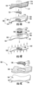
- FIG. 1A illustrates exemplary shapes for stiffener-members 108.
- FIG. 1B illustrates additional exemplary shapes for stiffener-members 108.
- the stiffener-members 108 may include hollowed portions 124, such as shown in FIG. 1B , such that the stiffness and surface density of the final design of the stiffener-member 108 are altered, ultimately altering the stiffness-to-mass ratio of the stiffener-member 108.
- the stiffener-member 108 may include an interior wall 122 defining a hollowed portion 124 in the stiffener-member 108.
- the hollowed portions 124 may cut vertically through the stiffener-member 108 (e.g., through each of the stiffener-member core material 114 and stiffener-member face sheets 116, 117 of the stiffener-member 108 (shown in FIGS. 2A-2G )).
- Such hollowing of the stiffener-members 108 may reduce the mass of the stiffener members 108 without significantly reducing the stiffness of the stiffener members 108. That is, the stiffener members 108 are still stiff enough to manipulate the dynamics of the anti-resonant panels 100 while not adding significant mass to the anti-resonant panels 100. Variations on this manipulation of the stiffener-members 108 may be used to obtain the desired anti-resonant performance.
- FIGS. 2A-2G provide various exemplary configurations of stiffener-members 108 on base panels 102.
- one or more stiffener-members 108 can be used with the base panel 102.
- the stiffener-members 108 control the global vibratory modes and enable the anti-resonant design.
- Stiffener-members 108 can encompass any shape, number, orientation, or location as needed to enable anti-resonant performance of the resulting anti-resonant panels 100.
- the stiffener-members 108 may be about 10% to about 30% of the total mass of the anti-resonant panel 100, such as about 15% to about 25% of the total mass of the anti-resonant panel 100, such as about 20% or less of the total mass of the anti-resonant panel 100.
- the stiffener-members 108 may cover less than 40% of the total surface area of the anti-resonant panel 100 (e.g., less than 40% of the total surface area of the side of the anti-resonant panel 100 on which the stiffener-member(s) 108 are placed), such as less than 35% of the total surface area of the anti-resonant panel 100 (e.g., less than 35% of the total surface area of the side of the anti-resonant panel 100 on which the stiffener-member(s) 108 are placed), such as less than 30% of the total surface area of the anti-resonant panel 100 (e.g., less than 30% of the total surface area of the side of the anti-resonant panel 100 on which the stiffener-member(s) 108 are placed), such as less than 25% of the total surface area of the anti-resonant panel 100 (e.g., less than 25% of the total surface area of the side of the anti-resonant panel 100 on which the stiffener-member(s) 108 are placed
- the stiffener-member 108 may be disposed along less than 25% of a total surface area of the base panel 102 and a mass of the stiffener-member 108 may be about 20% or less of a total mass of the anti-resonant panel 100.
- the stiffener-member 108 is able to increase the stiffness of the base panel 102 without significantly impacting the mass of the base panel 102 and provide control of the anti-resonant performance due to the discrete nature of the stiffener-members 108.
- the density and thickness of the stiffener-members 108 may vary based on the desired anti-resonant performance.
- the stiffener-members 108 will generally have a low mass density and high stiffness.
- the various configurations presented in FIGS. 2A-2G are a few examples of configurations that may alter the stiffness and mass-density properties of the resulting anti-resonant panel 100.
- the stiffener-members 108 of the present disclosure are not limited to those shown in FIGS. 2A-2G and may include a variety of materials in a variety of configurations without deviating from the intent and scope of the present disclosure.
- the stiffener-members 108 can be a combination of the following materials and/or other materials and designs that provide the desired lightweight but stiff combination and impart an acoustic boundary 132 to the base panel 102.
- the stiffener-member face sheets 116, 117 may be lightweight, strong material such as carbon fiber, fiberglass, or combinations thereof.
- the stiffener-member core material 114 may comprise foam (e.g., polyethylene terephthalate (PET) foam), be of a honeycomb construction (e.g., aramid honeycomb construction), otherwise have a porous structure, or combinations thereof.
- the stiffener-member core material 114 may comprise PET foam, aramid honeycomb construction, or combinations thereof.
- the stiffener-member face sheets 116, 117 may comprise carbon-fiber, fiberglass, combinations thereof, or other similar materials. In some embodiments, the stiffener-member face sheets 116, 117 may comprise carbon fiber, fiberglass, a fiber composite, or combinations thereof. Metal (e.g., aluminum) struts, trusses, or porous structures may be used to impart stiffness while not significantly increasing mass. Two different stiffener-member core materials 114 are shown in FIGS. 2A-2G . As the stiffener-members 108 are discrete, concentrated areas along the base panel 102, the materials may have a higher modulus than materials that would typically be used for construction of a base panel 102.
- stiffener-members 108 may be used in the stiffener-members 108 as such are generally smaller, more concentrated, discrete areas along the base panel 102 rather than the full length/width of the base panel 102.
- multiple stiffener-member face sheets 116 and/or 117 may be used to form the stiffener-member 108 and/or multiple stiffener-member core materials 114 may be used to form the stiffener-member 108.
- multiple stiffener-members 108 may be disposed on a base panel 102.
- the anti-resonant panel 100 of FIG. 2E includes a first stiffener-member 108a and a second stiffener-member 108b, each in respective defined areas 110a, 110b on the base panel 102.
- the first and second stiffener-members 108a, 108b are shown in FIG.
- compositions of the first and second stiffener-members 108a, 108b may be the same or different and more than two stiffener-members 108 may be incorporated on/into the base panel 102. Variations on the number and combination of these materials may be used to achieve the desired anti-resonant performance.
- the anti-resonant panels 100 may include stiffener-members 108 disposed on one of the two base panel face sheets 106, 107. In some embodiments, the anti-resonant panels 100 may include stiffener-members 108 disposed between the two base panel face sheets 106, 107 and adjacent to the base panel core material 104.
- FIGS. 2A-2E illustrate stiffener-members 108 applied to the base panel face sheets 106, 107 while FIGS. 2F and 2G illustrate stiffener-members 108 applied to the interior of the base panel 102 and covered by the base panel face sheets 106, 107. In particular, in FIGS.
- the stiffener-members 108 replace a portion of the base panel core material 104.
- a first stiffener-member face sheet 116 may be applied externally to the base panel face sheet 106 using an adhesive (attachment mechanism 146). Such placement of the stiffener-member face sheet 116 may further increase the bending stiffness of the defined area 110 in which the stiffener-member 108 is disposed.
- the stiffener-member 108 may include stiffener-member core material 114 and one or more stiffener-member face sheets 116, 117 or simply stiffener-member core material 114 without one or more stiffener-member face sheets 116, 117.
- Stiffener-member face sheets 116, 117 may be applied to the interior of the base panel 102 (e.g., under one or more base panel face sheets 106, 107 (shown in FIGS. 6A-6D )) and/or applied to the exterior of the base panel 102 (e.g., over one or more base panel face sheets 106, 107).
- the stiffener-members 108 may be designed to provide the desired degree of anti-resonant performance by including the stiffener-members 108 in specific regions (e.g., defined areas 110) of base panels 102 and with specific constructions. That is, the materials, size, shape, and configuration of materials for the stiffener-members 108 may be modified to achieve the desired anti-resonance behavior.
- the anti-resonant panel 100 may include two or more stiffener-members 108 (e.g., first and second stiffener-members 108a and 108b as shown in FIG. 2E ) each positioned along the base panel 102 in respective defined areas 110 (e.g., first and second defined areas 110a and 110b as shown in FIG. 2E ) of the base panel 102.
- the stiffener-member 108 may provide an efficient acoustic boundary on the base panel 102 thereby enabling alteration of the global vibratory modes of the anti-resonant panel 100 (that is, the vibratory modes of the whole base panel 102 such as the first and second principal modes and the anti-resonant mode in between).
- the stiffener-member 108 has a sandwich-type construction (e.g., comprising two stiffener-member face sheets 116, 117 surrounding a stiffener-member core material 114 on opposite sides of the core material 114), which may enable lightweight but high bending stiffness resulting in a sandwich-type stiffener member 108.
- the anti-resonant panel 100 may be configured to reduce noise propagation through the anti-resonant panel 100 at frequencies between about 300 Hz to about 1000 Hz.
- the anti-resonant panel 100 may include a stiffener-member 108 (e.g., stiffener-member 108 in FIGS. 1A-1B , 2A-2G , 4A-4C , and 5A-5B ) on a base panel 102 (e.g., base panel 102 in FIGS.
- one or more stiffener-members 108 are added to one or more base panels 102, in particular to one or more base panel face sheets 106, 107 to alter the stiffness-to-mass ratio of the base panel 102.
- the anti-resonant panels 100 include a base panel 102 comprising a base panel core material 104 and two base panel face sheets 106, 107, each of the two base panel face sheets 106, 107 adjacent to an opposite side of the base panel core material 104; and at least one stiffener-member 108 positioned along the base panel 102 in a defined area 110 of the base panel 102, the defined area 110 being less than a full area 112 of the base panel 102; wherein the stiffener-member 108 comprises a stiffener-member core material 114 and two stiffener-member face sheets 116, 117, each of the two stiffener-member face sheets 116, 117 adjacent to an opposite side of the stiffener-member core material 114, and wherein the stiffener
- the stiffener-member 108 may provide stiffness by being constructed as a sandwich-type stiffener-member comprising at least one stiffener-member face sheet 116, 117 and a stiffener-member core material 114 and being prepared with materials described herein.
- the stiffener-member 108 may add stiffness at a low mass density by including a hollowed portion 124 as shown in FIG. 1B and/or be disposed on the base panel as shown in FIGS. 5A-5b or 4A-4C .
- the one or more stiffener-members 108 are disposed on the exterior surface of the one or more base panel face sheets 106, 107.
- one or more stiffener-members 108 may be added to the interior base panel core material 104 and then surrounded by the base panel face sheets 106, 107.
- the one or more stiffener-members 108 may be applied to the base panel core material 104 and/or used in place of the base panel core material 104 in defined areas 110 of the base panel 102.
- One or more stiffener-members 108 may be added to defined areas 110 of the base panel 102 to alter the stiffness-to-mass ratio of the base panel 102 at specific points along the base panel 102.
- stiffener-member face sheets 116, 117, adhesive films or adhesive materials can be used to form the stiffener-members 108 and achieve the desired stiffness and specific mass properties of the final stiffener-member 108 and the resulting anti-resonant panel 100.
- FIGS. 1A-1B and 2A-2G are examples of embodiments that can effectively be used as stiffener-members 108 for anti-resonant performance. Combinations of these examples as well as other configurations of the stiffener-members 108 may be used in conjunction with the base panels 102 to provide anti-resonant panels 100 with the improved anti-resonant performance.
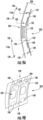
- stiffener-members 108 includes a perimeter-type stiffener-member 118 that is lightweight and further increases the stiffness of the anti-resonant panel 100.
- the anti-resonant panel 100 includes a perimeter-type stiffener-member 118 disposed along one or more edges 120 of the stiffener-member 108.
- perimeter-type stiffener-members 118 may be included to reinforce a stiffener-member 108, such as a sandwich-type stiffener-member 108 (see e.g., FIG. 3 ), or, in non-claimed examples, may be used alone as the stiffener-member 108.
- the perimeter-type stiffener member 118 is particularly effective in performance when disposed along the perimeter of a sandwich-type stiffener-member 108 to further improve the anti-resonant performance of the anti-resonant panel 100.
- FIG. 3 shows a lightweight perimeter-type stiffener member 118 enhancing the sandwich-type stiffener-member 108, which then engages to a sandwich-type base panel 102.
- the perimeter-type stiffener member 118 may be have a Z-shaped cross-section (e.g., two parallel horizontal portions are connected by a vertical portion, the two parallel horizontal portions independently connected to the vertical portion at opposite ends of the horizontal portions, forming a Z-shaped cross section) and extend along one or more sides or edges 120 of the sandwich-type stiffener-member 108.
- the perimeter-type stiffener member 118 traces the perimeter of the sandwich-type stiffener-member 108 along three edges 120 of the sandwich-type stiffener-member 108.
- the perimeter-type stiffener member 118 may trace one, two, or all edges 120 of a sandwich-type stiffener-member 108.
- the stiffness of the anti-resonant panel 100 is particularly increased when the perimeter-type stiffener member 118 connects three or more edges 120 enclosing a perimeter as shown in FIG. 3 .
- the perimeter-type stiffener member 118 may have a cross-section that is I-shaped (e.g., two parallel horizontal portions are connected by a vertical portion, the two parallel horizontal portions centered on top and on the bottom of the vertical portion, forming an I-shaped cross-section), L-shaped (e.g., a single horizontal portion is attached on the bottom of a single vertical portion forming an L-shaped cross-section), Z-shaped, T-shape (e.g., a single horizontal portion is attached on top of a single vertical portion forming a T-shaped cross section), etc. or may have any other suitable configuration to provide a lightweight stiffener member 108 to the sandwich-type base panel 102.
- I-shaped e.g., two parallel horizontal portions are connected by a vertical portion, the two parallel horizontal portions centered
- the materials for the stiffener-members 108 may be pre-qualified materials already suited for the aerospace or automotive industry. In some embodiments, the same materials that make up the base panel 102 may be used for the stiffener-members 108, though differing in configuration, size, and thickness to achieve the desired anti-resonant performance.
- the anti-resonant performance of the anti-resonant panels 100 can be further improved by maximizing the bonding rigidity of the stiffener-member 108 to the base panel 102.
- the engagement of the stiffener-member 108 to the base panel 102 may be as complete as possible, especially along the perimeter or edges 120 of the stiffener-member 108.
- FIGS 4A-4C provide exemplary methods of adjoining stiffener-members 108 to base panels 102.
- FIG. 4A provides a high-stiffness, highly-conformal stiffener-member 108 formed in a mold to fit the shape of the base panel 102.
- "conformal" refers to the shaping of the item to closely fit adjacent components.
- the surface of the stiffener-member 108 (e.g., one of the stiffener-member face sheets 116, 117) is immediately adjacent to the base panel 102 and follows the curvature of the base panel 102.
- the stiffener-member 108 geometry is traced and cut away to form the stiffener-member 108 for the anti-resonant panel 100.
- the stiffener-member 108 may be pre-fabricated as stiffener-member panel stock 150 in a mold. From this stiffener-member panel stock 150, a specific area predetermined to produce the desired anti-resonant performance is cut out (stiffener-member cut-out 152) and superimposed as the stiffener-member 108 to an existing base panel 102. This method is especially practical if specific defined areas 110 requiring the stiffener-members 108 are complex or highly contoured, as shown in FIG. 4A . This treatment allows for high bonding engagement of the stiffener-member 108 to the base panel 102, which can increase the effective stiffness of the resulting anti-resonant panel 100.
- the stiffener-member 108 may be joined to the base panel 102 by other methods.
- FIG. 4B shows an exemplary process of forming the stiffener-member 108 on the base panel 102.
- FIG. 4B illustrates an exemplary method of stiffener-member 108 formation by a layup process, in which the constituents (in this embodiment, the stiffener-member face sheets 116, 117, the attachment mechanisms 146, and the stiffener-member core material 114) that make up the stiffener-member 108 are flat, but flexible, allowing the constituents to take on the surface contours of the base panel 102 (including the base panel face sheets 106, 107 and base panel core material 104) during the layup process.
- the constituents in this embodiment, the stiffener-member face sheets 116, 117, the attachment mechanisms 146, and the stiffener-member core material 11
- the stiffener-member 108 and base panel 102 are then bonded together to form the anti-resonant panel 100.
- An autoclave may be used to achieve higher bonding pressures once the setup has been established, or sandbags may be applied over the attachment to aid in bonding.
- the method shown in FIG. 4B may be more cost effective and efficient than other methods.
- FIG. 4C illustrates another exemplary method of adjoining stiffener-members 108 to base panels 102.
- a stiffener-member 108 may be prepared, for example, by cutting out the stiffener-member 108 from stiffener-member panel stock 150 (see e.g., FIG. 4A ), building up the stiffener-member with pre-cut constituents of the stiffener-member (see e.g., FIG. 4B ), the like, or combinations thereof.
- the stiffener-member 108 includes a stiffener-member core material 114 and stiffener-member face sheets 116, 117.
- a portion of the base panel core material 104 may be removed to allow for the insertion of the stiffener-member 108.
- Base panel face sheets 106, 107 may then be applied to the base panel core material 104 and stiffener-member 108 forming the anti-resonant panel 100.
- the stiffener-member 108 is incorporated into the base panel 102 thereby imparting the stiffer properties of the stiffener-member 108 to the base panel 102 and providing a resulting anti-resonant panel 100 with a flush or regular surface.
- the stiffener-member 108 may be incorporated into the base panel 102 by adhering the stiffener-member 108 to the base panel core material 104 and then applying base panel face sheets 106, 107 over both the stiffener-member 108 and the base panel core material 104 without cutting out a portion of the base panel core material 104. Variations on these methods may be used without deviating from the intent of the present disclosure and other methods can be used to achieve similar results based on available supplies or capital.
- the stiffener-member 108 can be attached to the base panel 102 by several means, with some examples shown in FIGS. 5A and 5B .
- FIGS. 5A and 5B provide exemplary processes for attaching a stiffener-member 108 to a base panel 102.
- the stiffener-member 108 is pre-fabricated and attached by way of mechanical fasteners (e.g., attachment mechanism 146) to the base panel 102.
- FIG. 5A also shows a cross-section of the resulting anti-resonant panel 100.
- the stiffener-member 108 is pre-fabricated and attached by way of adhesive film (e.g., attachment mechanism 146) and an auto-clave layup to the base panel 102.
- FIG. 5B also shows a cross-section of the resulting anti-resonant panel 100 illustrating the direct attachment of the stiffener-member 108 to the base panel 102.
- bonding techniques can be used, such as hot press, vacuum bagging, sand-bagging, the like, and combinations thereof and various materials can be used such as screws, adhesive, adhesive film, rivet, and combinations thereof.
- a rigid foam-forming adhesive may be used to ensure gaps are securely filled and adhered between the two interfaces (e.g., between the stiffener-member 108 (e.g., one or more stiffener-member face sheets) and the base panel 102).
- the stiffener-member 108 e.g., one or more stiffener-member face sheets
- the base panel 102 e.g., one or more stiffener-member face sheets
- FIGS. 6A-6D are exemplary base panels 102, particularly sandwich-type base panels 102, which may be used for the anti-resonant panels 100 as described herein.
- Each of the base panels 102 depicted in FIGS. 6A-6D include base panel face sheets 106, 107 and base panel core material 104 making the panels sandwich-type base panels 102. While the embodiments illustrated in FIGS.
- the base panel face sheets 106, 107 may vary within an anti-resonant panel 100 (that is, different types (i.e., materials) of base panel face sheets 106, 107 may be used on opposite sides of the base panel core material 104 and/or along the same side of the base panel core material 104).
- different types (i.e., materials) of base panel face sheets 106, 107 may be used on opposite sides of the base panel core material 104 and/or along the same side of the base panel core material 104.
- the embodiments illustrated in FIGS. 6A-6D use the same base panel core material 104 for the length and width of the base panel 102, the base panel core material 104 may vary within an anti-resonant panel 100.
- FIG. 6A is a flat sandwich-type base panel 102 with carbon-fiber base panel face sheets 106, 107 surrounding an aramid honeycomb base panel core material 104.
- FIG. 6B is a contoured sandwich-type base panel 102 of the same materials used in FIG. 6A with a thicker base panel core material 104 and contoured shape (base panel face sheets 106, 107 and base panel core material 104).
- FIG. 6C is a flat sandwich-type composite base panel 102 with fiberglass base panel face sheets 106, 107 surrounding an aramid honeycomb base panel core material 104 with in-plane contoured cutouts.
- FIG. 6A is a flat sandwich-type base panel 102 with carbon-fiber base panel face sheets 106, 107 surrounding an aramid honeycomb base panel core material 104.
- FIG. 6B is a contoured sandwich-type base panel 102 of the same materials used in FIG. 6A with a thicker base panel core material 104 and contoured shape (base panel face sheets
- FIG. 6D is a sandwich-type base panel 102 composed of thin aluminum base panel face sheets 106, 107 surrounding a PET foam base panel core material 104.
- the thickness of the base panel 102, particularly the base panel core material 104, in FIG. 6D is varied along the base panel 102 to create a contoured portion 160 of the base panel 102.
- the contoured base panels 102 may include a variety of curvature and angles to provide the desired shape and configuration.
- the base panel 102 may be contoured in various portions of the base panel 102 to specifically fit the desired location in the wall in which the anti-resonant panel 100 is to be used and/or to achieve the desired noise-insulating performance of the anti-resonant panel 100.
- the base panels 102 of the present disclosure are not limited to those shown in FIGS. 6A-6D and may include a variety of materials in a variety of configurations without deviating from the intent and scope of the present disclosure.
- the base panels 102 in the anti-resonant panels 100 can be a combination of these materials and/or other materials and designs that create lightweight and stiff paneling with anti-resonant performance.
- the anti-resonant sound-blocking performance may become vulnerable to the low-frequency range of audible frequencies, e.g., 300 Hz-1000 Hz, as the effective acoustic boundaries expand.
- This behavior is usually governed by the creation of undesirable vibro-acoustic modes having characteristic geometric patterns super-positioned on the panel at distinct frequencies. Mitigation of these modes can be addressed by modifying specific locations on the panel, as determined from various tools used in acoustic measurement and modeling, with the use of the stiffener-members 108.
- Additional components may be added to the anti-resonant panels 100 to provide improved performance. For example, inertial members 126 (see e.g., FIG.
- reinforcing members 128 (see e.g., FIGS. 8A and 8B), grounding members 134 (see e.g., FIGS. 9A and 9B ), and combinations thereof may be added to strategic panel locations to further improve the anti-resonance of the anti-resonant panels 100. These treatments can further tune the anti-resonant performance of the anti-resonant panels 100.
- the additional components may provide a wider bandwidth of transmission loss, may shift the bandwidth to higher frequencies, or combinations thereof.
- inertial members 126 and/or grounding members 134 along the defined acoustic boundary 132 of the sub-divided anti-resonant panel 100 are effective to increase the quality factor (Q) of the anti-resonant performance, increasing the sound-blocking performance even further.
- Inertial members 126 are generally discrete high-density components added to the anti-resonant panel 100 to provide a relatively small amount of mass in a specific portion of the anti-resonant panels 100.
- the anti-resonant panel 100 may include at least one inertial member 126.
- the inertial member 126 is configured to provide a mass increase over the defined area 110 of the anti-resonant panel 100.
- one or more inertial members 126 may be added to the anti-resonant panel 100.
- the inertial members 126 include material(s) and have a geometry to increase the mass density of the anti-resonant panel 100 at the particular location of the inertial member 126.
- the inertial members 126 provide high mass density in a small diameter (e.g., the inertial members 126 generally have a smaller diameter than the diameter of the stiffener-members 108, but have a higher mass density than the mass density of the stiffener-members 108).
- the inertial members 126 may have a mass density of about 5, 10, or more times the mass density of the stiffener-members 108 and are generally too small in size to provide stiffness to the anti-resonant panels 100 (e.g., the inertial members 126 have a smaller diameter than the diameter of the stiffener-members 108 and do not provide the stiffness that the stiffener-members 108 are able to provide).
- the inertial member 126 may have a mass density of about 10 times a mass density of the stiffener-member 108.
- the mass density may be such that a high increase in mass is provided over a small diameter to effectively increase the mass at that location without significantly increasing the total mass of the anti-resonant panel 100.
- the stiffener-member 108 may increase the stiffness of the panel without significantly increasing the mass of the panel.
- the density of the inertial members 126 may be about 0.5 kg/m 3 to about 30 kg/m 3 , such as about 1 kg/m 3 to about 20 kg/m 3 .
- the inertial members 126 provide concentrated masses at a particular location that shift local modes out of the target frequency range or suppress the local vibrations (e.g., FIG. 15 ). In some embodiments, there is a diminishing return in transmission loss gained as mass increases with the incorporation of inertial members 126. Thus, the addition of inertial members 126 is a balance between the increase in mass and the desired transmission loss in the desired frequency range.
- the addition of the inertial members 126 as point-masses can help maintain anti-resonance with minimal mass penalty.
- the inertial members 126 may include solid aluminum, rubber, tungsten, ceramic, or a combination thereof as such materials provide a relatively high mass density without significantly increasing the mass of the panel.
- the inertial members 126 provided herein may be of any suitable geometry and material to provide a relatively small amount of mass to help tune the acoustic properties of the anti-resonant panels 100.
- the inertial members 126 may be fastened using attachment mechanisms (e.g., attachment mechanisms 146), such as mechanical fasteners, adhesives, other methods noted herein, the like, or combinations thereof.
- attachment mechanisms e.g., attachment mechanisms 146
- the inertial members 126 can embody any shape, the inertial members 126 are constrained to being effective as point-masses irrelevant of shape.
- FIG. 7 illustrates the incorporation of exemplary inertial members 126 to an anti-resonant panel 100.
- FIG. 7 illustrates both inertial members 126 and a stiffener-member 108 (one stiffener-member face sheet 116 and the stiffener-member core material 114 are shown) on a sandwich-type base panel 102 (including base panel face sheets 106, 107 and base panel core material 104) forming an anti-resonant panel 100.
- the anti-resonant panel 100 may include a reinforcing member 128.
- the reinforcing member 128 is disposed along a perimeter 130 of the defined area 110 of the base panel 102 and defines an acoustic boundary 132 for the defined area 110 of the base panel 102.
- the reinforcing members 128 divide the anti-resonant panels 100 acoustically by imposing a barrier at the particular location along the anti-resonant panel 100, forming acoustic boundaries 132.
- the reinforcing members 128 can help improve control of the overall acoustic performance of the anti-resonant panel 100 with such division.
- the reinforcing members 128 can be placed in any orientation and any number of the reinforcing members 128 may be used in positions suitable to improve the anti-resonant performance.
- the reinforcing members 128 may help delineate acoustic boundaries 132 of the anti-resonant panel 100, in particular non-planar or contoured anti-resonant panel 100.
- FIG. 8 illustrates cross-sectional profiles of exemplary reinforcing members 128 that can be used for the reinforcement of various anti-resonant panels 100.
- Solid construction-type and sandwich-type reinforcing members 128 are shown.
- the cross-sectional geometry of the reinforcing members 128 can embody several types commonly used in the industry (I-shaped, L-shaped, Z-shaped, T-shaped, etc.), as well as newer or more complex cross-sectional geometries that maximize the stiffness-to-mass ratio.
- the length and size of the reinforcing members 128 may be designed to achieve particular anti-resonant performance.
- the reinforcing members 128 can be made out of any type of material, can be a composite material, have a sandwich-type construction, the like, or combinations thereof suitable to provide a lightweight component with a high bending stiffness (e.g., comparable to the stiffener-member 108).
- the attachment mechanism 146 for the reinforcing members 128 can be those used in attaching the stiffener-members 108 described earlier, or other mechanisms favorable for constraining vibratory movement with a minimal mass-density penalty over the footprint of the reinforcing member 128.
- the reinforcing members 128 may include various materials, such as pre-approved composite materials, such as those found in the construction of base panels 102.
- the reinforcing members 128 can be configured in perimeter configurations similar to the perimeter-type stiffener-members 118 so long as the reinforcing members 128 enhance the partition of the anti-resonant panels 100 creating acoustic boundaries 132 for higher efficiency anti-resonant panels 100.
- the reinforcing members 128 are generally elongate members (length greater than width).
- FIG. 9A illustrates exemplary reinforcing members 128 that are able to further improve the anti-resonance control for the anti-resonant panels 100 and boost transmission loss. More specifically, FIG. 9A illustrates a profile view of a system 200 including reinforcing members 128 used to horizontally reinforce anti-resonant panels 100 employed as an aircraft cabin panel 202. FIG. 9B illustrates a system 200 including vertical sandwich-type reinforcing members 128 to reinforce portions of the anti-resonant panels 100 employed as an aircraft cabin panel 202. Various configurations of the reinforcing members 128 may be used to improve the anti-resonant performance of the anti-resonant panels.
- Periodically mounting the anti-resonant panels 100 to a structure 136 such as a fuselage skin 137 (see e.g., FIG. 14 ) or a window 224 (see e.g., FIGS. 9A and 9B ), may be used to further redefine the acoustic boundaries 132, favoring anti-resonant performance (see e.g., FIGS. 10A and 10B ).
- grounding members 134 can be used to anchor the anti-resonant panels 100 to other components of the structure 136, such as a fuselage skin 137 or a window 224.
- the anti-resonant panel 100 may include a grounding member 134.
- the grounding member 134 is configured to anchor the anti-resonant panel 100 to a structure 136, such as a fuselage skin 137 or a window 224, and define an acoustic boundary 132 for the defined area 110 of the base panel 102.
- Grounding members 134 may take advantage of existing parts of the structure 136 (e.g., those that have high mass, such as a fuselage skin 137 or a window 224) to provide the anti-resonant panels 100 more stable vibratory acoustic boundaries 132.
- the grounding members 134 can help isolate and control vibrations and improve the anti-resonant performance of the anti-resonant panel 100.
- the anti-resonant panels 100 are used in aircraft (see e.g., aircraft 145 in FIG. 13 )
- several locations along the fuselage skin 137 can be used as anchoring points to attach grounding members 134 to the anti-resonant panels 100 to further improve anti-resonant performance.
- Convenient anchoring locations on portions of the fuselage skin 137 can be used, such as the windows 224, stringers, circumferential frame portions, or similar points nearby.
- the selection of anchoring points for attaching grounding members 134 to the anti-resonant panels 100 can include nearby components as well that are anchored to the fuselage skin 137 to reduce the additional mass of fasteners or parts required to achieve effective anchoring performance.
- FIG. 10A illustrates a profile view of an exemplary system 200 including the anti-resonant panels 100 and the adjacent fuselage skin 137
- FIG. 10B illustrates a back-facing view of an exemplary system 200 including of anti-resonant panels 100 and the adjacent fuselage skin 137
- Exemplary grounding members 134 are illustrated.
- the grounding members 134 are attached at specific portions of the anti-resonant panel 100 to form suitable acoustic boundaries 132 favorable to anti-resonant performance.
- the grounding members 134 can include brackets, anchoring bolts, other fasteners, or combinations thereof that have the capacity to anchor the portion of anti-resonant panel 100 on which the grounding members 134 are attached and the adjoining fuselage skin 137. Further, damping can be added along the anchoring grounding member 134 to reduce induced vibration from the fuselage skin 137 to the anti-resonant panel 100 at the attachment point or area.
- the fuselage skin 137 located behind the trim panel 154 acts as the exterior vehicle body.
- the gap between these two components can be acoustically exploited, in which the overall acoustic attenuation can be increased over a wide bandwidth.
- This architecture may be referred to as a double-pane architecture.
- the trim panels 154 may be replaced with one or more anti-resonant panels 100 having a base panel 102 and one or more stiffener-members 108. Accordingly, the anti-resonant panel 100 act as an interior side wall panel that at least partially defines an enclosed cabin 155 of the aircraft 145.
- the double-pane acoustic effect generally has two low-frequency resonant modes, as shown for example in FIGS. 11A and 11B , then a rapid increase in acoustic attenuation as the frequency increases. If properly accounted for, the anti-resonance of the anti-resonant panel 100 and the double-pane effect can work together to extend the overall acoustic transmission loss through the anti-resonant panel 100 into the enclosed structure (e.g., enclosed cabin 155 of FIG. 14 ).
- FIGS. 11A and 11B illustrate exemplary double-pane effects caused by two structures (e.g., fuselage skin 137 and anti-resonant panel 100) resonating in phase with each other ( FIG. 11A ) and out of phase with each other ( FIG. 11B ).
- the stiffener-member 108 includes a stiffener-member core material 114 and two stiffener-member face sheets 116, 117.
- the stiffener-member 108 is configured to provide anti-resonant performance to the base panel 102.
- attaching the stiffener-member 108 to the base panel 102 may include composite layup, hot-pressing, vacuum-forming, vacuum bagging, vacuum assisted resin transfer molding (VARTM), or a combination thereof (step 1112).
- attaching the stiffener-member 108 to the base panel 102 may include incorporating at least one of an attachment mechanism 146 comprising a screw, adhesive, adhesive film, rivet, or a combination thereof to attach the stiffener-member 108 to the base panel 102 (step 1114).
- FIG. 12 illustrates an exemplary method 1100 of providing noise insulation to a structure (e.g., a fuselage skin 137) in accordance with some example embodiments described herein.
- method 1100 is illustrated which includes attaching at least one stiffener-member 108 to the base panel 102 (step 1110) (see e.g., FIGS. 2A-2G , 4A-4C , 5A and 5B and the description related to each provided herein).
- the method 1100 may also include providing a base panel 102 comprising a base panel core material 104 and two base panel face sheets 106, 107 (step 1108) (see e.g., FIGS. 6A-6D ).
- attaching the stiffener-member 108 to the base panel 102 may include composite layup, hot-pressing, vacuum-forming, vacuum bagging, VARTM, and combinations thereof (step 1112).
- Attaching the stiffener-member 108 to the base panel 102 may include incorporating at least one attachment mechanism 146 including a screw, adhesive, adhesive film, rivet, or combinations thereof to attach the stiffener-member 108 to the base panel 102, as shown in step 1114.
- Various embodiments as disclosed herein may be incorporated into methods of providing noise insulation.
- the method 1100 may include removing an interior portion 148 of the stiffener-member 108 creating a hollowed portion 124 in the stiffener-member 108 prior to attaching at least one stiffener-member 108 to the base panel 102 (step 1109).
- FIG. 13 is a flow chart for an exemplary method 1200 of forming an anti-resonant panel 100 in accordance with some example embodiments described herein.
- method 1200 includes forming a stiffener-member 108 configured to provide anti-resonant performance to a base panel 102 by disposing at least one stiffener-member face sheets 116 and/or 117 over a stiffener-member core material 114 (step 1210) and attaching the stiffener-member 108 to a defined area 110 of the base panel 102 (step 1220).
- Various embodiments as disclosed herein may be incorporated into methods of providing noise insulation.
- a system 200 may be provided that includes a structure 136 (e.g., fuselage skin 137) and at least one anti-resonant panel 100 adjacent the structure (e.g., fuselage skin 137).
- the structure 136 e.g., fuselage skin 137
- the structure 136 defines an exterior section 138a and an interior section 138b and may form an enclosed cabin 155.
- the structure 136 (e.g., fuselage skin 137) is adjacent to the anti-resonant panel 100 and may work in conjunction with the anti-resonant panel 100 to provide improved noise-insulation (see e.g., grounding members 134 discussed with regards to FIGS. 10A and 10B and/or double pane effect discussed with regards to FIGS. 11A and 11B ).
- the anti-resonant panel 100 is used in an aircraft (e.g., aircraft 145), where the aircraft is the system 200 having the anti-resonant panel 100.
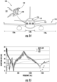
- FIG. 14 provides exemplary areas where the anti-resonant panels 100 may be used on an aircraft 145 and provides an example of anti-resonant panels 100 incorporated with the fuselage skin 137 of the aircraft 145 forming an enclosed cabin 155.
- the anti-resonant panels 100 may be added to the aircraft 145 as an addition or substitution where the trim panels 154 are located.
- the stiffener-members 108 may be incorporated onto a base panel 102, which enables broadband sound-blocking performance of the anti-resonant panel 100.
- FIG. 14 provides one example of the application of the stiffener-members 108; however, the stiffener-members 108 may be added to various locations throughout the enclosed cabin 155. As shown in FIG.
- the incorporation of the stiffener-members 108 to the base panels 102 provides improved sound blocking as compared to the base panel 102 alone. Sound waves 109 are reflected off the anti-resonant panels 100. The anti-resonant panels 100 thereby provide improved noise blocking for the enclosed cabin 155, particularly at low frequencies.
- noise insulation may be provided to an enclosed cabin 155.
- Noise insulation may be provided to an enclosed cabin 155 by positioning at least one anti-resonant panel 100 adjacent to the enclosed cabin 155, the at least one anti-resonant panel 100 comprising a base panel 102 and at least one stiffener-member 108 attached to the base panel 102, wherein the at least one stiffener-member 108 provides anti-resonant performance to the base panel 102 to reduce noise propagation into the enclosed cabin 155.
- positioning at least one anti-resonant panel 100 adjacent to the enclosed cabin 155 includes positioning the anti-resonant panel 100 as previously described adjacent the enclosed cabin 155.
- the at least one anti-resonant panel 100 may be coupled to the enclosed cabin 155.
- the at least one anti-resonant panel 100 may be coupled to the enclosed cabin 155 using grounding members 134.
- FIG. 15 illustrates an exemplary prediction using the finite element analysis (FEA) method and experimentally measured results.
- the performance shown in FIG. 15 is merely representative and is relative to the noise that may be blocked.
- the performance shown in FIG. 15 is not intended to limit the present disclosure.
- FIG. 15 shows the insertion loss performance of an anti-resonant panel 100 (solid line), along with the matched FEA prediction (depicted as diamonds).
- the dashed curve is the equivalent mass law prediction using an identical mass density of an isotropic plate.
- the anti-resonant panel 100 may provide improved noise blocking, particularly at relatively low frequencies, and much higher noise blocking than seen with an equivalent mass density.
- the equivalent mass to achieve the shown loss in noise is about sixteen (16) times that used in the anti-resonant panel 100. Other degrees of improvement may be possible.
- FIG. 16 illustrates an effect of adding exemplary inertial members 126 to an anti-resonant panel 100 to enable a wider bandwidth of anti-resonant performance in an exemplary embodiment.
- the addition of the inertial members 126 may provide a wider bandwidth of anti-resonant performance compared to an embodiment without the inertial member 126 (shown by triangles).
- the addition of the inertial members 126 may reduce dips in anti-resonant performance seen in embodiments without the inertial members 126.
- the inertial members 126 generally help tune the acoustic performance of the anti-resonant panel 100, providing a wider bandwidth of anti-resonant performance.
- the inertial members 126 may define a new acoustic boundary 132 point, line, or area, and may enable the creation of a better-defined anti-resonant panel 100.
- the inertial members 126 may help move the resonance frequencies away from the target frequency range.
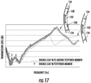
- FIG. 17 illustrates how the anti-resonance and double pane effects may add together to attenuate a very large acoustic frequency band gap.
- FIG. 17 illustrates an exemplary predicted transmission loss performance comparison using the double-pane effect between the untreated trim panels (dashed curve) (including a base panel 102 and grounding members 134) and anti-resonant trim panels (triangle marks) (including a base panel 102, grounding members 134, and stiffener-members 108).
- the low-frequency transmission-loss performance may increase, and any dips in the transmission loss may shift to a higher frequency thereby providing improved noise insulation for lower frequencies.
- the stiffener-member core material may comprise polyethylene terephthalate (PET) foam, aramid honeycomb construction, or combinations thereof.
- PET polyethylene terephthalate
- the stiffener-member face sheets may comprise carbon fiber, fiberglass, a fiber composite, or combinations thereof.
- the at least one inertial member may comprise solid aluminum, rubber, tungsten, ceramic, or a combination thereof.
- the anti-resonant panel may further comprise a reinforcing member, the reinforcing member disposed along a perimeter of the defined area of the base panel and defining an acoustic boundary for the defined area of the base panel.
- reference to "on” includes both embodiments in which a component is disposed directly on another component as well as embodiments in which one or more intervening layers or elements are disposed between the components.
Landscapes
- Engineering & Computer Science (AREA)
- Mechanical Engineering (AREA)
- Aviation & Aerospace Engineering (AREA)
- Physics & Mathematics (AREA)
- Acoustics & Sound (AREA)
- Multimedia (AREA)
- Manufacturing & Machinery (AREA)
- Transportation (AREA)
- Soundproofing, Sound Blocking, And Sound Damping (AREA)
- Building Environments (AREA)
- Body Structure For Vehicles (AREA)
- Laminated Bodies (AREA)
- Shielding Devices Or Components To Electric Or Magnetic Fields (AREA)
- Superstructure Of Vehicle (AREA)
- Vehicle Interior And Exterior Ornaments, Soundproofing, And Insulation (AREA)
Claims (15)
- Anti-Resonanz-Platte (100) aufweisend:eine Basisplatte (102) mit einem Basisplatten-Kernmaterial (104) und zwei Basisplatten-Deckschichten (106, 107), wobei die zwei Basisplatten-Deckschichten jeweils angrenzend an entgegengesetzte Seiten des Basisplatten-Kernmaterials angeordnet sind; undmindestens ein der Basisplatte in einem definierten Bereich (110) der Basisplatte hinzugefügtes Versteifungselement (108), wobei der definierte Bereich weniger als ein Gesamtbereich (112) der Basisplatte ist,wobei das mindestens eine Versteifungselement ein Versteifungselement-Kernmaterial (114) und zwei Versteifungselement-Deckschichten (116, 117) aufweist, wobei die Versteifungselement-Deckschichten jeweils angrenzend an entgegengesetzte Seiten des Versteifungselement-Kernmaterials angeordnet sind,dadurch gekennzeichnet, dass die Anti-Resonanz-Platte (100) ferner ein randartiges Versteifungselement (118) aufweist, das entlang einer oder mehrerer Kanten (120) des mindestens einen Versteifungselements (108) angeordnet ist.
- Anti-Resonanz-Platte (100) nach Anspruch 1, wobei das mindestens eine Versteifungselement (108) aus einem Material niedriger Massendichte hergestellt ist und konfiguriert ist, um der Basisplatte (102) Anti-Resonanz-Verhalten zu verleihen, dadurch, dass dem definierten Bereich (110) der Basisplatte Steifheit hinzugefügt ist, wobei das Material niedriger Massendichte aus einem der folgenden besteht: Kohlenstoff, Glasfaser, eine Kombination von Kohlenstoff und Glasfaser, ein Schaum, eine Wabenkonstruktion, eine poröse Struktur, oder eine Kombination eines Schaums, einer Wabenkonstruktion und einer porösen Struktur.
- Anti-Resonanz-Platte (100) nach Anspruch 1 oder 2, wobei das mindestens eine Versteifungselement (108) angeordnet ist:an einer der zwei Basisplatten-Deckschichten (106, 107); oderzwischen den zwei Basisplatten-Deckschichten und angrenzend an das Basisplatten-Kernmaterial (104).
- Anti-Resonanz-Platte (100) nach einem der Ansprüche 1 bis 3, wobei das mindestens eine Versteifungselement (108) entlang von weniger als 25% eines Gesamtflächenbereichs der Basisplatte (102) angeordnet ist und eine Masse des mindestens einen Versteifungselements ungefähr 20% oder weniger einer Gesamtmasse der Anti-Resonanz-Platte ist.
- Anti-Resonanz-Platte (100) nach einem der Ansprüche 1 bis 4, wobei das mindestens eine Versteifungselement (108) zwei oder mehr Versteifungselemente aufweist, die jeweils entlang der Basisplatte (102) in jeweiligen definierten Bereichen (110) der Basisplatte angeordnet sind.
- Anti-Resonanz-Platte (100) nach einem der Ansprüche 1 bis 5, wobei die Anti-Resonanz-Platte konfiguriert ist, um Schallausbreitung durch die Anti-Resonanz-Platte bei Frequenzen zwischen ungefähr 300Hz und ungefähr 1000Hz zu reduzieren.
- Anti-Resonanz-Platte (100) nach einem der Ansprüche 1 bis 6, wobei das mindestens eine Versteifungselement (108) eine Innenwand (112) aufweist, die einen hohlen Teil (124) in dem mindestens einen Versteifungselement definiert.
- Anti-Resonanz-Platte (100) nach einem der Ansprüche 1 bis 7, ferner aufweisend mindestens ein Trägheitselement (126), wobei das mindestens eine Trägheitselement konfiguriert ist, um eine Massenzunahme über dem definierten Bereich (110) der Anti-Resonanz-Platte bereitzustellen, vorzugsweise, wobei das mindestens eine Trägheitselement eine Massendichte von ungefähr zehn Mal einer Massendichte des mindestens einen Versteifungselements (108) hat.
- Anti-Resonanz-Platte (100) nach einem der Ansprüche 1 bis 8, ferner aufweisend ein Fundamentelement (134), wobei das Fundamentelement konfiguriert ist, um die Anti-Resonanz-Platte an einer Struktur (136) zu verankern und eine akustische Grenze (132) für den definierten Bereich (110) der Basisplatte (102) zu definieren.
- System (200) aufweisend:eine Struktur (136); unddie angrenzend an die Struktur angeordnete Anti-Resonanz-Platte (100) nach einem der Ansprüche 1 bis 9.
- System nach Anspruch 10, wobei die Struktur eine Haut (137) eines Rumpfs eines Flugzeugs aufweist.
- Verfahren (1100) zur Herstellung einer Anti-Resonanz-Platte (100) aufweisend:Bereitstellen einer Basisplatte (102) mit einem Basisplatten-Kernmaterial (104) und zwei Basisplatten-Deckschichten (106, 107), wobei die zwei Basisplatten-Deckschichten jeweils angrenzend an entgegengesetzte Seiten des Basisplatten-Kernmaterials angeordnet sind,Hinzufügen (1110) mindestens eines Versteifungselements (108) zu der Basisplatte in einem definierten Bereich (110) der Basisplatte, wobei der definierte Bereich weniger als ein Gesamtbereich (112) der Basisplatte ist, das mindestens eine Versteifungselement ein Versteifungselement-Kernmaterial (114) und zwei Versteifungselement-Deckschichten (116, 117) aufweist, die zwei Versteifungselement-Deckschichten jeweils angrenzend an entgegengesetzte Seiten des Versteifungselement-Kernmaterials angeordnet sind, wobei das mindestens eine Versteifungselement konfiguriert ist, um der Basisplatte Anti-Resonanz-Verhalten zu verleihen,wobei das Verfahren gekennzeichnet ist durch Hinzufügen eines randartigen Versteifungselements (118), das entlang einer oder mehrerer Kanten (120) des mindestens einen Versteifungselements (108) angeordnet wird.
- Verfahren (1100) nach Anspruch 12, wobei Anbringen (1110) des mindestens einen Versteifungselements (108) an der Basisplatte (102) Verbundwerkstoff-Legen und/oder Heißpressen und/oder Vakuumformen und/oder Vakuumverpacken und/oder vakuumgestütztes Kunstharzspritzpressen (1112) aufweist,
oder Einfügen (1114) mindestens eines Befestigungsmechanismus, wie Schraube und/oder Klebstoff und/oder Klebefolie und/oder Niet aufweist, um das mindestens eine Versteifungselement an der Basisplatte anzubringen. - Verfahren (1100) nach Anspruch 12 oder 13, ferner aufweisend Entfernen (1109) eines inneren Teils (148) des mindestens einen Versteifungselements (108), was einen hohlen Teil (124) in dem mindestens einen Versteifungselement erzeugt, vor Anbringen (1110) des mindestens einen Versteifungselements (108) an der Basisplatte (102).
- Verfahren (1100) nach einem der Ansprüche 12 bis 14, wobei das mindestens eine Versteifungselement (108) hinzugefügt wird:an einer der zwei Basisplatten-Deckschichten (106, 107); oderzwischen den zwei Basisplatten-Deckschichten und angrenzend an das Basisplatten-Kernmaterial (104).
Applications Claiming Priority (1)
| Application Number | Priority Date | Filing Date | Title |
|---|---|---|---|
| US15/840,902 US11056092B2 (en) | 2017-12-13 | 2017-12-13 | Anti-resonant panel and methods of making the same |
Publications (2)
| Publication Number | Publication Date |
|---|---|
| EP3499499A1 EP3499499A1 (de) | 2019-06-19 |
| EP3499499B1 true EP3499499B1 (de) | 2025-03-12 |
Family
ID=63878449
Family Applications (1)
| Application Number | Title | Priority Date | Filing Date |
|---|---|---|---|
| EP18200803.7A Active EP3499499B1 (de) | 2017-12-13 | 2018-10-16 | Anti-resonanz-platte und verfahren zur herstellung davon |
Country Status (6)
| Country | Link |
|---|---|
| US (1) | US11056092B2 (de) |
| EP (1) | EP3499499B1 (de) |
| JP (1) | JP7316037B2 (de) |
| CN (2) | CN120003696A (de) |
| BR (1) | BR102018075316B1 (de) |
| CA (1) | CA3023321C (de) |
Families Citing this family (4)
| Publication number | Priority date | Publication date | Assignee | Title |
|---|---|---|---|---|
| DE102017008097B4 (de) * | 2017-08-29 | 2019-06-27 | Webasto SE | Fahrzeug-Sandwichbauteil und Verfahren zum Herstellen eines Fahrzeug-Sandwichbauteils |
| US11315538B2 (en) * | 2017-12-13 | 2022-04-26 | The Boeing Company | Anti-resonant panels |
| CA3106654C (en) * | 2018-07-17 | 2023-10-03 | Certainteed Ceilings Corporation | Acoustic panels and methods for preparing them |
| CN112541289B (zh) * | 2020-12-15 | 2023-04-07 | 西南交通大学 | 一种轨道车辆车体铝型材结构的声振等效建模方法 |
Citations (1)
| Publication number | Priority date | Publication date | Assignee | Title |
|---|---|---|---|---|
| US20140326536A1 (en) * | 2011-10-04 | 2014-11-06 | Aircelle | Structural acoustic attenuation panel |
Family Cites Families (41)
| Publication number | Priority date | Publication date | Assignee | Title |
|---|---|---|---|---|
| US3087567A (en) | 1959-03-06 | 1963-04-30 | Bolt Beranek & Newman | High acoustic-energy transmission-loss panel and the like |
| US3822762A (en) | 1971-09-23 | 1974-07-09 | Mc Donnell Douglas Corp | Decorative acoustic panel |
| JPS5521015A (en) * | 1978-07-29 | 1980-02-14 | Masaru Sasaki | Sound proof material |
| US4778028A (en) | 1986-11-03 | 1988-10-18 | General Electric Company | Light viscoelastic damping structure |
| JPH02115797U (de) * | 1989-03-06 | 1990-09-17 | ||
| CA2297104A1 (en) | 1997-09-03 | 1999-03-11 | Christien Ellis | Trim panel comprising an integral acoustic system |
| JP3703130B2 (ja) | 2000-02-18 | 2005-10-05 | 河西工業株式会社 | 車両用防音材 |
| AU2001288421A1 (en) | 2000-08-25 | 2002-03-04 | Acentech, Inc. | Noise cancellation using a mechanical oscillator |
| JP2002129671A (ja) | 2000-10-24 | 2002-05-09 | Sekisui Chem Co Ltd | 制振防音材の製造方法 |
| US7070848B2 (en) * | 2002-10-21 | 2006-07-04 | Cascade Engineering, Inc. | Vehicle acoustic barrier |
| US6971475B2 (en) * | 2003-05-01 | 2005-12-06 | Collins & Aikman Products Co. | Vehicle trim components with selectively applied foam and methods of making same |
| US20050217933A1 (en) * | 2003-12-31 | 2005-10-06 | Shim Sung Young | Sound absorbing material for a vehicle |
| US7410126B2 (en) | 2004-12-20 | 2008-08-12 | Sikorsky Aircraft Corporation | Tunable acoustic absorption system for an aircraft cabin |
| US7246772B2 (en) | 2004-12-20 | 2007-07-24 | Sikorsky Aircraft Corporation | Acoustic absorption system for an aircraft interior trim panel system |
| US7837147B2 (en) * | 2005-03-18 | 2010-11-23 | The Boeing Company | Systems and methods for reducing noise in aircraft fuselages and other structures |
| ATE427245T1 (de) * | 2005-04-04 | 2009-04-15 | Rieter Technologies Ag | Hermetisches dunnes mehrschichtiges shallabsorbierendes element |
| US8079443B2 (en) | 2008-01-07 | 2011-12-20 | Pelzer Acoustic Products Gmbh | Aircraft trim panel with integrated adjustable acoustic properties |
| US20090183821A1 (en) * | 2008-01-23 | 2009-07-23 | Intellectual Property Holdings, Llc | Constrained layer damping system and method of making the same |
| JP2009198901A (ja) * | 2008-02-22 | 2009-09-03 | Yamaha Corp | 吸音構造、吸音構造群、音響室、吸音構造の調整方法及び騒音低減方法 |
| DE102008017357B4 (de) | 2008-04-04 | 2014-01-16 | Airbus Operations Gmbh | Akustisch optimiertes Kabinenwandelement und seine Verwendung |
| US20090250292A1 (en) | 2008-04-08 | 2009-10-08 | Howa Textile Industry Co., Ltd. | Automotive sound-absorbing material |
| FR2934288B1 (fr) * | 2008-07-24 | 2014-02-14 | Weber & Broutin Sa | Dispositif d'amelioration acoustique pour sous-couche de revetement. |
| DE102008062701A1 (de) | 2008-12-17 | 2010-07-01 | Airbus Deutschland Gmbh | Flugzeugkabinenpaneel mit Kerntaschen zur Schallabsorption |
| GB0904099D0 (en) * | 2009-03-10 | 2009-04-22 | Bpb Ltd | Laminated acoustic soundproofing panel |
| AU2010310882B2 (en) * | 2009-10-21 | 2011-11-24 | Bellmax Acoustic Pty Ltd | Acoustic panel |
| ATE552584T1 (de) | 2010-03-09 | 2012-04-15 | Autoneum Technologies Ag | Isolierendes autoverkleidungsteil |
| US8997920B2 (en) * | 2010-11-24 | 2015-04-07 | Faist Chemtec Gmbh | Method and damping element for reducing the natural vibration of a component |
| US9168880B2 (en) * | 2011-03-22 | 2015-10-27 | Shiloh Industries, Inc. | Panel assembly having multi-layer patch for sound damping |
| CN103975385B (zh) | 2011-10-06 | 2018-04-10 | Hrl实验室有限责任公司 | 高带宽抗共振膜 |
| US8770343B2 (en) | 2011-11-23 | 2014-07-08 | The Boeing Company | Noise reduction system for composite structures |
| US20140000980A1 (en) * | 2012-06-20 | 2014-01-02 | International Automotive Components Group North America, Inc. | Sound Attenuating Composite Articles And Methods Of Making Same |
| US8881864B2 (en) * | 2012-10-04 | 2014-11-11 | International Automation Components Group North America, Inc. | Motor vehicle acoustic insulator, methods of manufacture and use thereof |
| JP6132520B2 (ja) | 2012-11-21 | 2017-05-24 | 東海旅客鉄道株式会社 | 吸音パネル |
| US8857563B1 (en) | 2013-07-29 | 2014-10-14 | The Boeing Company | Hybrid acoustic barrier and absorber |
| US8869933B1 (en) | 2013-07-29 | 2014-10-28 | The Boeing Company | Acoustic barrier support structure |
| US9222229B1 (en) | 2013-10-10 | 2015-12-29 | Hrl Laboratories, Llc | Tunable sandwich-structured acoustic barriers |
| WO2015129394A1 (ja) | 2014-02-25 | 2015-09-03 | 新日鐵住金株式会社 | 輸送機器用部品およびパネル部材 |
| US10140968B2 (en) * | 2014-05-02 | 2018-11-27 | Ashmere Holdings Pty Ltd | Acoustic absorption and methods of manufacture |
| WO2016025058A1 (en) | 2014-08-12 | 2016-02-18 | Hrl Laboratories, Llc | Progressive stiffness structural-acoustic sandwich panel |
| US10040535B2 (en) * | 2015-12-02 | 2018-08-07 | Embraer S.A. | Composite accoustical panels especially useful for interior panel assemblies of aircraft passenger cabins |
| JP6482040B2 (ja) | 2017-08-25 | 2019-03-13 | 東京ブラインド工業株式会社 | ペーパーコア材を使った吸音パネル |
-
2017
- 2017-12-13 US US15/840,902 patent/US11056092B2/en active Active
-
2018
- 2018-10-16 EP EP18200803.7A patent/EP3499499B1/de active Active
- 2018-11-06 CA CA3023321A patent/CA3023321C/en active Active
- 2018-11-13 CN CN202510140685.8A patent/CN120003696A/zh active Pending
- 2018-11-13 CN CN201811344246.5A patent/CN109911172B/zh active Active
- 2018-11-28 JP JP2018222342A patent/JP7316037B2/ja active Active
- 2018-12-06 BR BR102018075316-9A patent/BR102018075316B1/pt active IP Right Grant
Patent Citations (1)
| Publication number | Priority date | Publication date | Assignee | Title |
|---|---|---|---|---|
| US20140326536A1 (en) * | 2011-10-04 | 2014-11-06 | Aircelle | Structural acoustic attenuation panel |
Also Published As
| Publication number | Publication date |
|---|---|
| JP7316037B2 (ja) | 2023-07-27 |
| CA3023321A1 (en) | 2019-06-13 |
| CN109911172B (zh) | 2025-02-28 |
| BR102018075316A2 (pt) | 2019-11-05 |
| US20190180729A1 (en) | 2019-06-13 |
| BR102018075316B1 (pt) | 2023-10-31 |
| US11056092B2 (en) | 2021-07-06 |
| CN120003696A (zh) | 2025-05-16 |
| JP2019113837A (ja) | 2019-07-11 |
| CN109911172A (zh) | 2019-06-21 |
| EP3499499A1 (de) | 2019-06-19 |
| CA3023321C (en) | 2025-09-23 |
Similar Documents
| Publication | Publication Date | Title |
|---|---|---|
| US11315538B2 (en) | Anti-resonant panels | |
| EP3499499B1 (de) | Anti-resonanz-platte und verfahren zur herstellung davon | |
| US9284727B2 (en) | Acoustic barrier support structure | |
| US8857563B1 (en) | Hybrid acoustic barrier and absorber | |
| US20250084908A1 (en) | Designs and manufacturing methods for lightweight hyperdamping materials providing large attenuation of broadband-frequency structure-borne sound | |
| US7631727B2 (en) | Sandwich structure with frequency-selective double wall behavior | |
| EP0931309B1 (de) | Einrichtung zum absorbieren und/oder dämpfen von schallwellen | |
| US20110186380A1 (en) | Soundproofing Panel | |
| JP6185859B2 (ja) | 車体パネル構造体 | |
| EP2597032B1 (de) | Geräuschunterdrückungssystem für Verbundstrukturen | |
| EP2554091B1 (de) | Schalldämpfende sandwichplatte mit perforation | |
| JP7496212B2 (ja) | 減音パネル、及び、その構築及び設置を行うための方法 | |
| AU2018214044B2 (en) | Composite sound absorption panel assembly | |
| EP3670329B1 (de) | Zweiwege-akustikplatte | |
| CN106042468A (zh) | 一种宽频隔音蜂窝板 | |
| RU2405216C2 (ru) | Слоистая конструкция, имеющая частотно-избирательные характеристики двойной степени | |
| EP3885124B1 (de) | Verfahren zur herstellung einer schallabsorbierenden platte unter verwendung von waben und schallabsorbierende platte mit durch dieses verfahren hergestellten waben | |
| JP5238324B2 (ja) | 鉄道車両用パネルでの防音方法とそれに用いる鉄道車両用防音パネル構造 | |
| JP6996913B2 (ja) | 構造体、並びに該構造体を含む遮音材、制振材、材料及び各種部材 | |
| US9272768B2 (en) | Soundproofing cladding panel, and an aircraft | |
| Zverev et al. | Investigation of the efficiency of application of a vibration-absorbing material with a reinforcing layer for improving sound insulation of structural elements of the fuselage | |
| DE202017106206U1 (de) | Schall-Dämm-Material | |
| Owen et al. | Transmission loss properties of honeycomb/conventional metal panels | |
| Al-Zubi et al. | Sound and vibration considerations of some materials for automotive engineering applications |
Legal Events
| Date | Code | Title | Description |
|---|---|---|---|
| PUAI | Public reference made under article 153(3) epc to a published international application that has entered the european phase |
Free format text: ORIGINAL CODE: 0009012 |
|
| STAA | Information on the status of an ep patent application or granted ep patent |
Free format text: STATUS: REQUEST FOR EXAMINATION WAS MADE |
|
| 17P | Request for examination filed |
Effective date: 20181016 |
|
| AK | Designated contracting states |
Kind code of ref document: A1 Designated state(s): AL AT BE BG CH CY CZ DE DK EE ES FI FR GB GR HR HU IE IS IT LI LT LU LV MC MK MT NL NO PL PT RO RS SE SI SK SM TR |
|
| AX | Request for extension of the european patent |
Extension state: BA ME |
|
| RBV | Designated contracting states (corrected) |
Designated state(s): AL AT BE BG CH CY CZ DE DK EE ES FI FR GB GR HR HU IE IS IT LI LT LU LV MC MK MT NL NO PL PT RO RS SE SI SK SM TR |
|
| STAA | Information on the status of an ep patent application or granted ep patent |
Free format text: STATUS: EXAMINATION IS IN PROGRESS |
|
| 17Q | First examination report despatched |
Effective date: 20201124 |
|
| RAP3 | Party data changed (applicant data changed or rights of an application transferred) |
Owner name: THE BOEING COMPANY |
|
| REG | Reference to a national code |
Ref country code: DE Ref legal event code: R079 Free format text: PREVIOUS MAIN CLASS: G10K0011168000 Ipc: B32B0003080000 Ref document number: 602018080006 Country of ref document: DE |
|
| GRAP | Despatch of communication of intention to grant a patent |
Free format text: ORIGINAL CODE: EPIDOSNIGR1 |
|
| STAA | Information on the status of an ep patent application or granted ep patent |
Free format text: STATUS: GRANT OF PATENT IS INTENDED |
|
| RIC1 | Information provided on ipc code assigned before grant |
Ipc: G10K 11/168 20060101ALI20240530BHEP Ipc: B32B 27/12 20060101ALI20240530BHEP Ipc: B32B 3/12 20060101ALI20240530BHEP Ipc: B32B 3/08 20060101AFI20240530BHEP |
|
| INTG | Intention to grant announced |
Effective date: 20240618 |
|
| GRAJ | Information related to disapproval of communication of intention to grant by the applicant or resumption of examination proceedings by the epo deleted |
Free format text: ORIGINAL CODE: EPIDOSDIGR1 |
|
| STAA | Information on the status of an ep patent application or granted ep patent |
Free format text: STATUS: EXAMINATION IS IN PROGRESS |
|
| GRAP | Despatch of communication of intention to grant a patent |
Free format text: ORIGINAL CODE: EPIDOSNIGR1 |
|
| STAA | Information on the status of an ep patent application or granted ep patent |
Free format text: STATUS: GRANT OF PATENT IS INTENDED |
|
| INTC | Intention to grant announced (deleted) | ||
| INTG | Intention to grant announced |
Effective date: 20241004 |
|
| P01 | Opt-out of the competence of the unified patent court (upc) registered |
Free format text: CASE NUMBER: APP_55122/2024 Effective date: 20241008 |
|
| GRAS | Grant fee paid |
Free format text: ORIGINAL CODE: EPIDOSNIGR3 |
|
| GRAA | (expected) grant |
Free format text: ORIGINAL CODE: 0009210 |
|
| STAA | Information on the status of an ep patent application or granted ep patent |
Free format text: STATUS: THE PATENT HAS BEEN GRANTED |
|
| AK | Designated contracting states |
Kind code of ref document: B1 Designated state(s): AL AT BE BG CH CY CZ DE DK EE ES FI FR GB GR HR HU IE IS IT LI LT LU LV MC MK MT NL NO PL PT RO RS SE SI SK SM TR |
|
| REG | Reference to a national code |
Ref country code: GB Ref legal event code: FG4D |
|
| REG | Reference to a national code |
Ref country code: CH Ref legal event code: EP |
|
| REG | Reference to a national code |
Ref country code: DE Ref legal event code: R096 Ref document number: 602018080006 Country of ref document: DE |
|
| REG | Reference to a national code |
Ref country code: IE Ref legal event code: FG4D |
|
| PG25 | Lapsed in a contracting state [announced via postgrant information from national office to epo] |
Ref country code: RS Free format text: LAPSE BECAUSE OF FAILURE TO SUBMIT A TRANSLATION OF THE DESCRIPTION OR TO PAY THE FEE WITHIN THE PRESCRIBED TIME-LIMIT Effective date: 20250612 |
|
| PG25 | Lapsed in a contracting state [announced via postgrant information from national office to epo] |
Ref country code: FI Free format text: LAPSE BECAUSE OF FAILURE TO SUBMIT A TRANSLATION OF THE DESCRIPTION OR TO PAY THE FEE WITHIN THE PRESCRIBED TIME-LIMIT Effective date: 20250312 |
|
| PG25 | Lapsed in a contracting state [announced via postgrant information from national office to epo] |
Ref country code: ES Free format text: LAPSE BECAUSE OF FAILURE TO SUBMIT A TRANSLATION OF THE DESCRIPTION OR TO PAY THE FEE WITHIN THE PRESCRIBED TIME-LIMIT Effective date: 20250312 |
|
| REG | Reference to a national code |
Ref country code: LT Ref legal event code: MG9D |
|
| PG25 | Lapsed in a contracting state [announced via postgrant information from national office to epo] |
Ref country code: NO Free format text: LAPSE BECAUSE OF FAILURE TO SUBMIT A TRANSLATION OF THE DESCRIPTION OR TO PAY THE FEE WITHIN THE PRESCRIBED TIME-LIMIT Effective date: 20250612 |
|
| PG25 | Lapsed in a contracting state [announced via postgrant information from national office to epo] |
Ref country code: HR Free format text: LAPSE BECAUSE OF FAILURE TO SUBMIT A TRANSLATION OF THE DESCRIPTION OR TO PAY THE FEE WITHIN THE PRESCRIBED TIME-LIMIT Effective date: 20250312 |
|
| REG | Reference to a national code |
Ref country code: NL Ref legal event code: MP Effective date: 20250312 |
|
| PG25 | Lapsed in a contracting state [announced via postgrant information from national office to epo] |
Ref country code: LV Free format text: LAPSE BECAUSE OF FAILURE TO SUBMIT A TRANSLATION OF THE DESCRIPTION OR TO PAY THE FEE WITHIN THE PRESCRIBED TIME-LIMIT Effective date: 20250312 |
|
| PG25 | Lapsed in a contracting state [announced via postgrant information from national office to epo] |
Ref country code: GR Free format text: LAPSE BECAUSE OF FAILURE TO SUBMIT A TRANSLATION OF THE DESCRIPTION OR TO PAY THE FEE WITHIN THE PRESCRIBED TIME-LIMIT Effective date: 20250613 Ref country code: BG Free format text: LAPSE BECAUSE OF FAILURE TO SUBMIT A TRANSLATION OF THE DESCRIPTION OR TO PAY THE FEE WITHIN THE PRESCRIBED TIME-LIMIT Effective date: 20250312 |
|
| REG | Reference to a national code |
Ref country code: AT Ref legal event code: MK05 Ref document number: 1774693 Country of ref document: AT Kind code of ref document: T Effective date: 20250312 |
|
| PG25 | Lapsed in a contracting state [announced via postgrant information from national office to epo] |
Ref country code: NL Free format text: LAPSE BECAUSE OF FAILURE TO SUBMIT A TRANSLATION OF THE DESCRIPTION OR TO PAY THE FEE WITHIN THE PRESCRIBED TIME-LIMIT Effective date: 20250312 |
|
| PG25 | Lapsed in a contracting state [announced via postgrant information from national office to epo] |
Ref country code: SE Free format text: LAPSE BECAUSE OF FAILURE TO SUBMIT A TRANSLATION OF THE DESCRIPTION OR TO PAY THE FEE WITHIN THE PRESCRIBED TIME-LIMIT Effective date: 20250312 |
|
| PG25 | Lapsed in a contracting state [announced via postgrant information from national office to epo] |
Ref country code: SM Free format text: LAPSE BECAUSE OF FAILURE TO SUBMIT A TRANSLATION OF THE DESCRIPTION OR TO PAY THE FEE WITHIN THE PRESCRIBED TIME-LIMIT Effective date: 20250312 |
|
| PG25 | Lapsed in a contracting state [announced via postgrant information from national office to epo] |
Ref country code: PT Free format text: LAPSE BECAUSE OF FAILURE TO SUBMIT A TRANSLATION OF THE DESCRIPTION OR TO PAY THE FEE WITHIN THE PRESCRIBED TIME-LIMIT Effective date: 20250714 |
|
| PG25 | Lapsed in a contracting state [announced via postgrant information from national office to epo] |
Ref country code: PL Free format text: LAPSE BECAUSE OF FAILURE TO SUBMIT A TRANSLATION OF THE DESCRIPTION OR TO PAY THE FEE WITHIN THE PRESCRIBED TIME-LIMIT Effective date: 20250312 Ref country code: IT Free format text: LAPSE BECAUSE OF FAILURE TO SUBMIT A TRANSLATION OF THE DESCRIPTION OR TO PAY THE FEE WITHIN THE PRESCRIBED TIME-LIMIT Effective date: 20250312 |
|
| PG25 | Lapsed in a contracting state [announced via postgrant information from national office to epo] |
Ref country code: AT Free format text: LAPSE BECAUSE OF FAILURE TO SUBMIT A TRANSLATION OF THE DESCRIPTION OR TO PAY THE FEE WITHIN THE PRESCRIBED TIME-LIMIT Effective date: 20250312 |
|
| PG25 | Lapsed in a contracting state [announced via postgrant information from national office to epo] |
Ref country code: CZ Free format text: LAPSE BECAUSE OF FAILURE TO SUBMIT A TRANSLATION OF THE DESCRIPTION OR TO PAY THE FEE WITHIN THE PRESCRIBED TIME-LIMIT Effective date: 20250312 Ref country code: EE Free format text: LAPSE BECAUSE OF FAILURE TO SUBMIT A TRANSLATION OF THE DESCRIPTION OR TO PAY THE FEE WITHIN THE PRESCRIBED TIME-LIMIT Effective date: 20250312 |
|
| PG25 | Lapsed in a contracting state [announced via postgrant information from national office to epo] |
Ref country code: RO Free format text: LAPSE BECAUSE OF FAILURE TO SUBMIT A TRANSLATION OF THE DESCRIPTION OR TO PAY THE FEE WITHIN THE PRESCRIBED TIME-LIMIT Effective date: 20250312 |
|
| PG25 | Lapsed in a contracting state [announced via postgrant information from national office to epo] |
Ref country code: SK Free format text: LAPSE BECAUSE OF FAILURE TO SUBMIT A TRANSLATION OF THE DESCRIPTION OR TO PAY THE FEE WITHIN THE PRESCRIBED TIME-LIMIT Effective date: 20250312 |
|
| PG25 | Lapsed in a contracting state [announced via postgrant information from national office to epo] |
Ref country code: IS Free format text: LAPSE BECAUSE OF FAILURE TO SUBMIT A TRANSLATION OF THE DESCRIPTION OR TO PAY THE FEE WITHIN THE PRESCRIBED TIME-LIMIT Effective date: 20250712 |