EP3498952A1 - Vehicle door handle mounting structure - Google Patents
Vehicle door handle mounting structure Download PDFInfo
- Publication number
- EP3498952A1 EP3498952A1 EP18212052.7A EP18212052A EP3498952A1 EP 3498952 A1 EP3498952 A1 EP 3498952A1 EP 18212052 A EP18212052 A EP 18212052A EP 3498952 A1 EP3498952 A1 EP 3498952A1
- Authority
- EP
- European Patent Office
- Prior art keywords
- decoration member
- outer panel
- door handle
- bracket
- vehicle door
- Prior art date
- Legal status (The legal status is an assumption and is not a legal conclusion. Google has not performed a legal analysis and makes no representation as to the accuracy of the status listed.)
- Withdrawn
Links
Images




Classifications
-
- E—FIXED CONSTRUCTIONS
- E05—LOCKS; KEYS; WINDOW OR DOOR FITTINGS; SAFES
- E05B—LOCKS; ACCESSORIES THEREFOR; HANDCUFFS
- E05B83/00—Vehicle locks specially adapted for particular types of wing or vehicle
- E05B83/16—Locks for luggage compartments, car boot lids or car bonnets
- E05B83/18—Locks for luggage compartments, car boot lids or car bonnets for car boot lids or rear luggage compartments
-
- B—PERFORMING OPERATIONS; TRANSPORTING
- B60—VEHICLES IN GENERAL
- B60R—VEHICLES, VEHICLE FITTINGS, OR VEHICLE PARTS, NOT OTHERWISE PROVIDED FOR
- B60R13/00—Elements for body-finishing, identifying, or decorating; Arrangements or adaptations for advertising purposes
- B60R13/005—Manufacturers' emblems, name plates, bonnet ornaments, mascots or the like; Mounting means therefor
-
- E—FIXED CONSTRUCTIONS
- E05—LOCKS; KEYS; WINDOW OR DOOR FITTINGS; SAFES
- E05B—LOCKS; ACCESSORIES THEREFOR; HANDCUFFS
- E05B79/00—Mounting or connecting vehicle locks or parts thereof
- E05B79/02—Mounting of vehicle locks or parts thereof
- E05B79/06—Mounting of handles, e.g. to the wing or to the lock
-
- E—FIXED CONSTRUCTIONS
- E05—LOCKS; KEYS; WINDOW OR DOOR FITTINGS; SAFES
- E05B—LOCKS; ACCESSORIES THEREFOR; HANDCUFFS
- E05B79/00—Mounting or connecting vehicle locks or parts thereof
- E05B79/10—Connections between movable lock parts
- E05B79/22—Operative connections between handles, sill buttons or lock knobs and the lock unit
-
- E—FIXED CONSTRUCTIONS
- E05—LOCKS; KEYS; WINDOW OR DOOR FITTINGS; SAFES
- E05B—LOCKS; ACCESSORIES THEREFOR; HANDCUFFS
- E05B83/00—Vehicle locks specially adapted for particular types of wing or vehicle
- E05B83/16—Locks for luggage compartments, car boot lids or car bonnets
-
- E—FIXED CONSTRUCTIONS
- E05—LOCKS; KEYS; WINDOW OR DOOR FITTINGS; SAFES
- E05B—LOCKS; ACCESSORIES THEREFOR; HANDCUFFS
- E05B85/00—Details of vehicle locks not provided for in groups E05B77/00 - E05B83/00
- E05B85/10—Handles
-
- E—FIXED CONSTRUCTIONS
- E05—LOCKS; KEYS; WINDOW OR DOOR FITTINGS; SAFES
- E05Y—INDEXING SCHEME ASSOCIATED WITH SUBCLASSES E05D AND E05F, RELATING TO CONSTRUCTION ELEMENTS, ELECTRIC CONTROL, POWER SUPPLY, POWER SIGNAL OR TRANSMISSION, USER INTERFACES, MOUNTING OR COUPLING, DETAILS, ACCESSORIES, AUXILIARY OPERATIONS NOT OTHERWISE PROVIDED FOR, APPLICATION THEREOF
- E05Y2201/00—Constructional elements; Accessories therefor
- E05Y2201/10—Covers; Housings
- E05Y2201/11—Covers
-
- E—FIXED CONSTRUCTIONS
- E05—LOCKS; KEYS; WINDOW OR DOOR FITTINGS; SAFES
- E05Y—INDEXING SCHEME ASSOCIATED WITH SUBCLASSES E05D AND E05F, RELATING TO CONSTRUCTION ELEMENTS, ELECTRIC CONTROL, POWER SUPPLY, POWER SIGNAL OR TRANSMISSION, USER INTERFACES, MOUNTING OR COUPLING, DETAILS, ACCESSORIES, AUXILIARY OPERATIONS NOT OTHERWISE PROVIDED FOR, APPLICATION THEREOF
- E05Y2400/00—Electronic control; Electrical power; Power supply; Power or signal transmission; User interfaces
- E05Y2400/80—User interfaces
- E05Y2400/85—User input means
- E05Y2400/856—Actuation thereof
- E05Y2400/858—Actuation thereof by body parts, e.g. by feet
- E05Y2400/86—Actuation thereof by body parts, e.g. by feet by hand
-
- E—FIXED CONSTRUCTIONS
- E05—LOCKS; KEYS; WINDOW OR DOOR FITTINGS; SAFES
- E05Y—INDEXING SCHEME ASSOCIATED WITH SUBCLASSES E05D AND E05F, RELATING TO CONSTRUCTION ELEMENTS, ELECTRIC CONTROL, POWER SUPPLY, POWER SIGNAL OR TRANSMISSION, USER INTERFACES, MOUNTING OR COUPLING, DETAILS, ACCESSORIES, AUXILIARY OPERATIONS NOT OTHERWISE PROVIDED FOR, APPLICATION THEREOF
- E05Y2900/00—Application of doors, windows, wings or fittings thereof
- E05Y2900/50—Application of doors, windows, wings or fittings thereof for vehicles
- E05Y2900/53—Type of wing
- E05Y2900/548—Trunk lids
Definitions
- the present disclosure relates to vehicle door handle mounting structures including a decoration member that is mounted on the outer surface of a vehicle door (e.g., a back door) and a door handle that is mounted on the decoration member.
- a decoration member that is mounted on the outer surface of a vehicle door (e.g., a back door) and a door handle that is mounted on the decoration member.
- a decoration member e.g., a garnish
- a door handle is mounted on the back side of the decoration member in order to use the decoration member as a door handle.
- the decoration member is mounted on the outer surface of a back door and a door handle is mounted on the back side of the decoration member in order to use the decoration member as a door handle as described above, the decoration member is subjected to load when the user operates the door handle.
- the decoration member therefore need be firmly fixed to the back door.
- the decoration member In the case where the decoration member is used as a door handle, the decoration member is typically fixed to the back door with bolts and nuts. Accordingly, if the decoration member is a wide member, the decoration member can be fixed at many points to the back door. The decoration member can thus be firmly fixed to the back door.
- the decoration member is a narrow member like a mascot
- the decoration member cannot be fixed at many points to the back door.
- the decoration member can be fixed at only a few points in its upper part to the back door.
- the decoration member therefore cannot be firmly fixed to the back door, resulting in insufficient mounting rigidity of the decoration member on the back door.
- a vehicle door handle mounting structure is a vehicle door handle mounting structure including: a vehicle door including an outer panel having an opening; a decoration member mounted on a front side of the outer panel and having a coupling portion that is placed in the opening of the outer panel; a door handle mounted in the decoration member; and a bracket coupled to the coupling portion from a back side of the outer panel and, together with the decoration member, holding the outer panel therebetween.
- the door handle is mounted in the decoration member mounted on the outer panel of the vehicle door.
- the decoration member can also be used as the door handle.
- the coupling portion of the decoration member is placed in the opening of the outer panel, the bracket is coupled to the coupling portion from a back side of the outer panel, and the outer panel is held between the bracket and the decoration member.
- the decoration member is thus firmly fixed to the outer panel.
- Sufficient mounting rigidity of the decoration member on the outer panel i.e., the vehicle door
- fixing parts such as bolts and nuts.
- the decoration member may have a decoration member body and a housing mounted on a back side of the decoration member body and supporting the door handle.
- the housing may have a back-side case portion fixed to a back surface of the decoration member, and an accommodating recess formed so as to be recessed from a front side toward a back side of the back-side case portion and accommodating the door handle.
- the accommodating recess may project from the back side of the back-side case portion to form the coupling portion.
- the accommodating recess of the decoration member in which the door handle is placed also serves as the coupling portion. Accordingly, the coupling portion need not be provided separately, whereby reduction in size of the decoration member is achieved.
- an outer peripheral edge of the decoration member may be placed on the front side of the outer panel.
- the bracket may have a holding portion that is placed over the outer peripheral edge of the decoration member from the back side of the outer panel.
- the outer panel may be held between the outer peripheral edge of the decoration member and the holding portion of the bracket.
- the outer peripheral edge of the decoration member together with the bracket holds the outer panel therebetween.
- the outer panel is thus stably held between the decoration member and the bracket. Since the outer peripheral edge of the decoration member is used to hold the outer panel, a relatively large region of the outer panel can be held. The outer panel is thus stably held between the decoration member and the bracket.
- the outer panel may have in its surface a stepped recessed portion on which the decoration member is mounted.
- a stepped peripheral wall of the stepped recessed portion may be tilted outward in a radial direction.
- the outer peripheral edge of the decoration member may be placed on a front side of the stepped peripheral wall of the stepped recessed portion.
- the holding portion of the bracket may be placed on a back side of the stepped peripheral wall of the stepped recessed portion.
- the stepped peripheral wall of the stepped recessed portion for mounting the decoration member which is tilted outward in the radial direction, is used as a portion that is held between the decoration member and the bracket. Accordingly, a relatively large region of the outer panel can be used as the portion that is held between the decoration member and the bracket. Since the stepped peripheral wall used as the portion that is held between the decoration member and the bracket is tilted outward, the position of the portion that is held between the decoration member and the bracket is restrained from being displaced in the direction of a main surface of the outer panel.
- the coupling portion of the decoration member may be inserted through the opening and project beyond the back side of the outer panel.
- the bracket may have a cover portion coupled to the coupling portion so as to cover the coupling portion, the holding portion formed at an outer peripheral edge of the cover portion, and a reinforcing rib formed in a recessed corner that is formed in the cover portion and the holding portion.
- the reinforcing rib is formed in the recessed corner that is formed in the cover portion and the holding portion of the bracket. This improves rigidity of the holding portion of the bracket. The outer panel is thus firmly fixed between the bracket and the decoration member.
- the bracket may have a drain groove in its inner peripheral surface.
- the drain groove may extend in both the cover portion and the holding portion, open in a tip end of the holding portion, and project toward outside of the bracket to form the reinforcing rib.
- the bracket since the bracket has the drain groove in its inner peripheral surface, water (e.g., water drops) having entered the bracket is effectively drained to the outside of the bracket. Since the drain groove forms the reinforcing rib, the drain groove can also be used as the reinforcing rib.
- the bracket may be placed over the decoration member other than a part of the decoration member which is mounted on the outer panel.
- the bracket is placed over the decoration member other than the part of the decoration member which is mounted on the outer panel. Accordingly, the portion of the outer panel which is held between the bracket and the decoration member does not overlap the part of the decoration member which is mounted on the outer panel. This allows the entire decoration member to have uniform mounting rigidity on the outer panel. Since the bracket is not placed on the entire back side of the decoration member, reduction in size of the bracket is achieved.
- the decoration member may be a mascot having substantially the same lateral width as that of the door handle, and the door handle may have an electric door switch.
- the mascot i.e., a relatively narrow decoration member
- the door handle has an electric door switch, which contributes to reduction in size of the mascot.
- the present disclosure thus provides a vehicle door handle mounting structure capable of providing sufficient mounting rigidity of a decoration member on a vehicle door even if the decoration member is a narrow member.
- FIGS. 1 to 14 An embodiment of the present disclosure will be described with reference to FIGS. 1 to 14 .
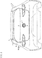
- FIG. 1 is a front view of a rear part of a vehicle 2 to which a vehicle door handle mounting structure 1 according to the embodiment has been applied.
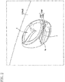
- FIG. 2 is a perspective view of a decoration member 5 mounted on the outer surface of a vehicle door (e.g., back door) 3 as viewed from below.
- FIGS. 3A and 3B are a perspective view and a front view, respectively, of the vehicle door handle mounting structure 1 as viewed from the back side of an outer panel 31.
- the vehicle door handle mounting structure 1 has been applied to a door handle 4 of the vehicle door 3 that opens and closes a trunk opening 2a at the back of the vehicle 2.
- the door handle 4 also serves as the decoration member 5 mounted on the outer surface of the vehicle door 3.
- the vehicle 2 is, e.g., a wagon or a hatchback.
- the vehicle 2 has a trunk at the back.
- the vehicle 2 also has the trunk opening 2a and the vehicle door 3 at the back.
- the trunk opening 2a communicates with the trunk and the vehicle door 3 opens and closes the trunk opening 2a.
- the vehicle door 3 is, e.g., a hatch-type door.
- the upper side portion of the vehicle door 3 is swingably hinged to the upper side portion of the trunk opening 2a so that the vehicle door 3 can swing upward and downward about near its upper side portion as a rotation axis L.
- the vehicle door 3 includes the outer panel 31 that forms the outer surface of the vehicle door 3.
- the decoration member 5 is mounted on the outer surface of the outer panel 31.
- the decoration member 5 is, e.g., a mascot with a logo etc. thereon (i.e., a relatively narrow decoration member).
- the decoration member 5 has a laterally long elliptical shape as viewed from the front, is somewhat thick, and projects from the outer surface of the outer panel 31.
- the decoration member 5 has an accommodating space therein, and the door handle 4 that is operated to open and close the vehicle door 3 is accommodated in the accommodating space.
- the decoration member 5 has an opening 5a at its lower end, which communicates with the accommodating space. The user can unlock the vehicle door 3 by inserting his/her finger(s) into the inside of the decoration member 5 through the opening 5a at the lower end of the decoration member 5 and operating the door handle 4. The user can open the vehicle door 3 by holding the decoration member 5 and swinging the vehicle door 3 upward.
- the decoration member 5 is fixed to the outer panel 31 by fixing parts 7 (e.g., fixing bolts 521g and nuts N1) and fixing parts 8 (e.g., fixing pins 521h).
- fixing parts 7 e.g., fixing bolts 521g and nuts N1
- fixing parts 8 e.g., fixing pins 521h
- a bracket 9 is disposed on the back side of the decoration member 5 with the outer panel 31 interposed therebetween.
- the bracket 9 is coupled to the decoration member 5 with the outer panel 31 interposed therebetween by coupling parts 10 (e.g., coupling bolts 522d and nuts N2).
- the outer panel 31 is held between the decoration member 5 and the bracket 9 by this coupling, and the decoration member 5 is further fixed to the outer panel 31 by this holding.
- FIGS. 4 and 5 are exploded perspective views of the vehicle door handle mounting structure 1 as viewed from the rear and the front, respectively.
- FIGS. 6A and 6B are a perspective view and a front view, respectively, of the decoration member 5 disposed in an opening 312 of the outer panel 31 as viewed from the back side of the outer panel 31.
- FIG. 7 is a perspective view of the bracket 9 as viewed from the front (i.e., the front side).
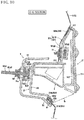
- FIGS. 8 to 11 are sectional views taken along lines A-A, B-B, C-C, and D-D in FIG. 3B , respectively.
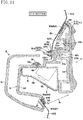
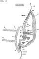
- FIGS. 12 to 14 are sectional views taken along lines E-E, F-F, and G-G in FIG. 6B , respectively.
- the outer panel 31 has a stepped recessed portion 311, an opening 312, and through holes 313 (see FIG. 9 ), 314 (see FIG. 11 ).
- the decoration member 5 is mounted on the stepped recessed portion 311, a housing 52, described below, of the decoration member 5 is disposed in the opening 312, and the fixing parts 7, 8 for fixing the decoration member 5 are inserted through the through holes 313, 314.
- the outer contour of the stepped recessed portion 311 is the same in shape and size (e.g., a substantially elliptical shape as viewed from the front) as the outer contour of a decoration member body 51, described below, of the decoration member 5.
- the stepped recessed portion 311 is recessed as viewed from an outer surface 31a of the outer panel 31 and protrudes as viewed from a back surface 31b of the outer panel 31.
- the stepped recessed portion 311 includes a flat bottom wall 311a and a stepped peripheral wall 311b.
- the stepped peripheral wall 311b stands from the entire outer peripheral edge of the bottom wall 311a.
- the bottom wall 311a has a substantially elliptical shape
- the stepped peripheral wall 311b has a substantially elliptical ring shape and is tilted so that its tip end (i.e., the end on the front side of the outer panel 31) is located more outside in the radial direction than its base end is.
- the bottom wall 311a has in its lower half the opening 312 where a coupling portion 522, described below, of the decoration member 5 is disposed.
- the opening 312 opens in the entire lower half of the bottom wall 311a.
- the bottom wall 311a has in its upper half the through holes 313, 314 for fixing the decoration member 5.
- the bottom wall 311a has two through holes 313 and two through holes 314.
- the two through holes 313 are formed next to each other near the middle part in the lateral direction of the upper half of the bottom wall 311a, and the two through holes 314 are formed on both sides in the lateral direction of the upper half of the bottom wall 311a (i.e., on the right and left sides of the two through holes 313), one on each side.
- the vehicle door handle mounting structure 1 includes the decoration member 5, the bracket 9, and the door handle 4.
- the decoration member 5 is mounted on the front side of the stepped recessed portion 311 of the outer panel 31.
- the bracket 9 is coupled to the decoration member 5 from the back side of the outer panel 31 and together with the decoration member 5 holds the outer panel 31 therebetween.
- the door handle 4 is mounted in the decoration member 5.
- the decoration member 5 and the bracket 9 are made of, e.g., resin (plastic etc.).
- the decoration member 5 includes the decoration member body 51 with a logo etc. thereon, and the housing 52 accommodating the door handle 4.
- the decoration member body 51 includes an outer case 511, a fixing base 512, and an elastic member 513.
- the door handle 4 and the housing 52 are fixed to the fixing base 512, and the elastic member 513 is disposed in the clearance between the outer case 511 and the outer panel 31.
- the outer case 511 has a shallow plate shape that is substantially elliptical as viewed from the front.
- the outer case 511 includes a bottom wall 511 a and an outer peripheral wall 511b that stands from the outer peripheral edge of the bottom wall 511a toward the back side of the bottom wall 511 a.
- the bottom wall 511a has a plate shape that is substantially elliptical as viewed from the front.
- the bottom wall 511a has a logo 511c on its outer surface 511d (see FIG. 5 ).
- the logo 511c is mounted so as to project from the outer surface 511d of the bottom wall 511a.
- the logo 511c is a separate member (e.g., resin or metal) from the bottom wall 511a and is fixed to the bottom wall 511a from the back side of the bottom wall 511a by screws or is fixed to the bottom wall 511a by an adhesive.
- the bottom wall 511a has on its back surface 511e positioning projections 511f for positioning the fixing base 512 and the housing 52, fixing bosses 511g for fixing the housing 52, and an engaged portion 511h that is engaged by an engaging portion 521a, described below, of the housing 52 (see FIG. 4 ).
- the positioning projections 511f have a bar shape and stand on the right and left sides of the upper part of the bottom wall 511a (see FIG. 11 ).
- the fixing bosses 511g have a cylindrical shape and have in their tip end faces a hole 511g1 into which a screw B1 for fixing the housing 52 is screwed (see FIG. 12 ).
- the fixing bosses 511g stand on the right and left sides of the middle part in the vertical direction of the bottom wall 511a.
- the engaged portion 511h has a laterally long box shape that opens in its lower surface.
- the engaged portion 511h is formed on the bottom wall 511a such that the side surface of the engaged portion 511h which is located on the rear side of the vehicle is integral with the bottom wall 511a (see FIG. 8 ).
- the outer peripheral wall 511b is tilted so that its tip end is located more outside in the radial direction than its base end (i.e., the end on the bottom wall 511a side) is.
- An upper peripheral wall 511b1, a lower peripheral wall 511b2, a left peripheral wall 511b3, and a right peripheral wall 511b4 are connected in a ring shape to form the outer peripheral wall 511b.
- the upper peripheral wall 511b1 has a relatively small height (length in the direction from the tip end to the base end of the upper peripheral wall 511b), and the lower peripheral wall 511b2 has a relatively large height.
- the heights of the left peripheral wall 511b3 and the right peripheral wall 511b4 increase gradually so that the height on the lower peripheral wall 511b2 side is larger than that on the upper peripheral wall 511b1 side (see FIG. 5 ).
- the lower peripheral wall 511b2 has the opening 5a.
- the opening 5a is formed in substantially the entire lower peripheral wall 511b2 and has a laterally long rectangular shape (see FIG. 2 ). Since the lower peripheral wall 511b2 has a relatively large height as described above, the opening 5a has a sufficiently large size (that is, such a size that the user can easily insert his/her finger(s) into the opening 5a when operating the door handle 4 to open the vehicle door 3, and can easily hold the peripheral edge of the opening 5a when opening the vehicle door 3).
- the fixing base 512 has a plate shape that is substantially rectangular as viewed in plan, and has approximately such a size that the fixing base 512 is inscribed in the contour of the bottom wall 511a of the outer case 511.
- the fixing base 512 is fixed to the bottom wall 511a by screws or an adhesive such that the back side of the fixing base 512 faces the back side of the bottom wall 511a of the outer case 511.
- the lower end of the fixing base 512 extends to a position near the lower end of the bottom wall 511a of the outer case 511 (i.e., near the upper end of the opening 5a).
- the fixing base 512 has through holes 512a for positioning the outer case 511, positioning bosses 512b for positioning the housing 52, a fixing boss 512c for fixing the housing 52, fixing pieces 512d for fixing the housing 52, fixing retaining portions 512e for fixing the door handle 4, and a clearance filling wall 512f for filling the clearance between the door handle 4 and the opening 5a of the outer case 511 (see FIG. 4 ).
- the through holes 512a are formed on the right and left sides of the upper part of the fixing base 512 (i.e., at positions corresponding to the positioning projections 511f) so as to extend through the fixing base 512 (see FIG. 11 ).
- the positioning projections 511f of the outer case 511 are loosely fitted in the through holes 512a, whereby the outer case 511 and the fixing base 512 are roughly positioned relative to each other.
- the positioning bosses 512b have a substantially semicircular cylinder shape and stand on the right and left sides of the middle part in the vertical direction of the surface of the fixing base 152 (e.g., below the through holes 512a) (see FIG. 11 ).
- the positioning bosses 512b have a hole 512b1 in their tip end faces.
- Positioning projections 521d, described below, of the housing 52 are fittingly inserted through the holes 512b1. The fixing base 512 and the housing 52 are thus positioned relative to each other.
- the fixing boss 512c has a substantially semicircular cylinder shape and stands in the middle part in the lateral direction of the upper part of the surface of the fixing base 512 (see FIG. 8 ).
- the fixing boss 512c has a hole 512c1 in its tip end face so that a screw B2 for fixing the housing 52 is screwed therein.
- the fixing pieces 512d stand from the right and left sides of the lower part of the surface of the fixing base 512 toward the front side of the surface of the fixing piece 512d, and are bent so that the halves on the tip end side of the fixing pieces 512d project toward the right and left sides of the fixing base 512 (see FIG. 14 ).
- the halves on the tip end side of the fixing pieces 512d are disposed below the fixing bosses 511g of the outer case 511 (see FIG. 12 ).
- the halves on the tip end side of the fixing pieces 512d have a hole 512d1 so that a screw B3 for fixing the housing 52 is screwed therethrough.
- each fixing retaining portion 512e has a pair of retaining walls 512el standing on the surface of the fixing base 512 (see FIG. 14 ).
- the retaining walls 512el extend in the vertical direction and are separated from each other.
- Retaining grooves 512e2 that retain a stopper portion 42c, described below, of the door handle 4 are formed in the opposing side surfaces of the retaining walls 512e1.
- Each retaining groove 512e2 extends in the vertical direction and opens in the upper end face of the retaining wall 512e1.
- the stopper portion 42c of the door handle 4 is inserted into the retaining grooves 512e2 from above the pair of retaining walls 512e1, whereby the door handle 4 is fixed to the fixing base 512.
- the clearance filling wall 512f has a middle wall 512f1 and right and left side walls 512f2.
- the middle wall 512f1 stands on the lower end of the surface of the fixing base 512, and the right and left side walls 512f2 project from the middle wall 512f to the right and left sides.
- the middle wall 512f1 fills the clearance between the upper side of the opening 5a of the outer case 511 and the door handle 4 (see FIG. 8 ).
- the right and left side walls 512f2 fill the clearances between the right and left sides of the opening 5a and the door handle 4 (see FIG. 2 ).
- the elastic member 513 covers the inner peripheral surface of the outer peripheral wall 511b and covers the tip end face of the outer peripheral wall 511b (see FIGS. 8 and 13 ).
- the tip end (i.e., a portion that covers the tip end face of the outer peripheral wall 511b) of the elastic member 513 contacts the outer surface of the outer panel 31. This contact restrains water from the outside from entering a vehicle body through the opening 312 of the outer panel 31.
- the elastic member 513 extends along the inner half of the tip end face of the outer peripheral wall 511b in the thickness direction of the outer peripheral wall 511b. This makes it difficult for the elastic member 513 to be seen from the outside of the decoration member 5.
- the housing 52 has a back-side case portion 521, an accommodating recess 522, and a rubber elastic member 523, and a urethane elastic member 524.
- the back-side case portion 521 is fixed to the back side of the decoration member body 51.
- the accommodating recess 522 is formed in the back-side case portion 521 and accommodates the door handle 4.
- the back-side case portion 521 has a shallow plate shape whose outer contour is substantially the same in shape and size as the outer contour of the decoration member body 51.
- the back-side case portion 521 is shaped so that it can be fitted in the stepped recessed portion 311 of the outer panel 31.
- the back-side case portion 521 includes a bottom wall 5211 and an outer peripheral wall 5212 that stands form the outer peripheral edge of the bottom wall 5211 toward the decoration member body 51.
- the bottom wall 5211 is a portion that is fitted on the bottom wall 311a of the stepped recessed portion 311, and the outer peripheral wall 5212 is a portion that is fitted on the stepped peripheral wall 311b of the stepped recessed portion 311.
- the bottom wall 5211 has a plate shape (e.g., substantially elliptical as viewed from the front) and is substantially the same in shape and size as the bottom wall 311a of the stepped recessed portion 311 of the outer panel 31.
- the bottom wall 5211 has the accommodating recess 522.
- the rubber elastic member 523 has a strip shape and extends along the lower half (i.e., a portion that overlaps the lower half of the opening 312 of the outer panel 31) of the entire circumferential length of the peripheral edge on the tip end side of the outer peripheral surface of the outer peripheral wall 5212.
- the tip end of the elastic member 523 projects from the tip end of the outer peripheral wall 5212, is tilted outward of the outer peripheral wall 5212, and contacts the surface of the outer panel 31 (see FIG. 8 ). This contact restrains water from the outside from entering the vehicle body from the clearance between the opening 312 of the outer panel 13 and the housing 52 through the opening 312.
- the portion of the outer peripheral surface of the outer peripheral wall 5212 on which the elastic member 523 is provided is recessed like a step. The outer peripheral surface of the outer peripheral wall 5212 is thus flush with the outer surface of the elastic member 523.
- the urethane elastic member 524 has an endless strip shape and extends along the entire circumferential length of the peripheral edge on the tip end side of the outer peripheral surface of the outer peripheral wall 5212.
- the elastic member 524 contacts the surface of the outer panel 31 (see FIG. 8 ). This contact restrains water from the outside from entering the vehicle body from the clearance between the opening 312 of the outer panel 31 and the housing 52 through the opening 312.
- a lower half (i.e., a portion that overlaps the lower half of the opening 312) 524a in the circumferential direction of the elastic member 524 is located behind the tip end of the elastic member 523 (see FIG. 8 ). The pressure of water from the outside is thus reduced by the tip end of the elastic member 523 and the water is almost completely stopped by the lower half 524a of the elastic member 524.
- An upper half (i.e., a portion that overlaps the upper half of the opening 312) 524b in the circumferential direction of the elastic member 524 is located behind the elastic member 513 of the outer case 511 (see FIG. 8 ). The pressure of water from the outside is thus reduced by the elastic member 513 and the water is almost completely stopped by the upper half 524b of the elastic member 524.
- the elastic member 524 also serves as a cushioning material between the housing 52 and the outer panel 31.
- the accommodating recess 522 is formed on the lower half of the bottom wall 5211 so as to be recessed from the front side (the decoration member body 51 side) toward the back side (the outer panel 31 side) of the back-side case portion 521, and projects from the back side of the back-side case portion 521.
- This projecting portion i.e., the accommodating recess 522
- the accommodating recess 522 is hereinafter also referred to as the coupling portion 522.
- the accommodating recess 522 is substantially in the shape of a rectangular parallelepiped box that opens in its front surface. The open surface of the accommodating recess 522 is coupled so that the accommodating recess 522 communicates with the back-side case portion 521 in the lower half of the bottom wall 5211 of the back-side case portion 521.
- the accommodating recess 522 has through holes 522a (see FIG. 11 ), an opening 522b (see FIG. 8 ), a hook portion 522c (see FIG. 6 ), and the coupling bolts 522d (see FIG. 10 ). Screws B5 for fixing the door handle 4 are inserted through the through holes 522a. A wire 43 for the door handle 4 accommodated in the accommodating recess 522 is drawn out through the opening 522d. The wire 43 is fixed to the hook portion 522c. The coupling bolts 522d are coupled to the bracket 9.
- the through holes 522a are formed on the right and left sides of the upper peripheral wall of the accommodating recess 522, and the opening 522b is formed in the middle part of the upper peripheral wall of the accommodating recess 522.
- the hook portion 522c is mounted near the opening 522b of the upper peripheral wall of the accommodating recess 522.
- the coupling bolts 522d stand on the bottom of the accommodating recess 522 so as to project from the back side of the accommodating recess 522. More specifically, a total of three coupling bolts 522d, two in the upper part and one in the lower part, are provided on the bottom of the accommodating recess 522.
- the coupling bolt 522d includes a threaded portion 522d1, a head 522d2 formed at the base end of the threaded portion 522d1, and a flange portion 522d3 formed on the threaded portion 522d1 so as to be separated from the head 522d2.
- the flange portion 522d3 has a disc shape and projects outward in the radial direction of the threaded portion 522d1 (see FIG. 10 ).
- Fixing portions 522e for fixing the coupling bolt 522d are formed on the outer main surface of the bottom of the accommodating recess 522 (see FIGS. 6 and 10 ).
- the fixing portion 522e is a substantially U-shaped peripheral wall that opens on its one side.
- This peripheral wall has a retaining groove 522f formed in its inner peripheral surface so as to extend in the circumferential direction. Both ends of the retaining groove 522f open in both end faces of the peripheral wall.
- the head 522d2 of the coupling bolt 522d is inserted into the inside of the peripheral wall from the open side of the peripheral wall, and the peripheral edge of the head 522d2 is retained by the retaining groove 522f, whereby the coupling bolt 522d is fixed to the bottom of the accommodating recess 522.
- the threaded portion 522d1 of the coupling bolt 522d projects from the back side of the accommodating recess 522, and the peripheral wall is held between the head 522d2 and the flange portion 522d3 of the coupling bolt 522d.
- the back-side case portion 521 includes the engaging portion 521a and positioning through holes 521b for positioning the outer case 511, and fixing through holes 521c through which the screws B1 for fixing the outer case 511 are screwed (see FIG. 5 ).
- the engaging portion 521a is a portion that engages with the engaged portion 511h of the outer case 511 (see FIG. 8 ).
- the engaging portion 521a is formed in the upper part (i.e., a portion corresponding to the engaged portion 511h) of the inner peripheral surface of the outer peripheral wall 5212 of the back-side case portion 521.
- the engaging portion 521a stands from the inner peripheral surface of the outer peripheral wall 512 toward the front side of the back-side case portion 521.
- the half on the tip end side of the engaging portion 521a is bent upward.
- the half on the tip end side of the engaging portion 521a is bent upward.
- the half on the tip end side of the engaging portion 521a is inserted into the open lower surface of the engaged portion 511h, whereby the engaging portion 521a engages with the engaged portion 511h.
- the housing 52 and the outer case 511 are positioned relative to each other by this engagement.
- the positioning through hole 521b is a hole through which the positioning projection 511f of the outer case 511 is fittingly inserted (see FIG. 11 ).
- the back-side case portion 521 has bottomed cylindrical boss 521b1 formed on the right and left sides (i.e., portions corresponding to the positioning projections 511f) of the upper part of the surface of the bottom wall 5211 so as to project from the upper part of the surface of the bottom wall 5211.
- Each boss 521b1 has the positioning through hole 521b in its tip end face.
- the positioning projections 511f are fittingly inserted in the positioning through holes 521b.
- the housing and the outer case 511 are also positioned relative to each other by this insertion.
- the fixing through hole 521c is a hole through which the screw B1 for fixing the housing 52 to the fixing bosses 511g of the outer case 511 is inserted (see FIG. 13 ).
- the fixing through holes 521c are formed on the right and left sides (i.e., portions corresponding to the fixing bosses 511g) of the middle part in the vertical direction of the bottom wall 5211 of the back-side case portion 521.
- the screws B1 are inserted through the fixing through holes 521c from the back side of the housing 52 and are screwed into the holes 511g1 of the fixing bosses 511g, whereby the housing 52 is fixed to the outer case 511.
- the back-side case portion 521 i.e., the housing 52
- the outer case 511 has positioning portions (i.e., the engaging portion 521a and the positioning through holes 521b)
- the outer case 511 has corresponding positioning portions (i.e., the engaged portion 511h and the positioning projections 511f).
- the back-side case portion 521 has positioning projections 521d for positioning the fixing base 512 and fixing through holes 521e, 521f for fixing the fixing base 512 (see FIG. 5 ).
- the positioning projection 521d is a projection that is fittingly inserted through the hole 512b1 of the positioning boss 512b of the fixing base 512 (see FIG. 11 ).
- the positioning projections 521d stand on the right and left sides of the surface of the bottom wall 5211 of the back-side case portion 521. For example, the positioning projections 521d are located below the positioning through holes 521b.
- the positioning projections 521d are fittingly inserted through the holes 512b1 of the fixing base 512, whereby the housing 52 and the fixing base 512 are positioned relative to each other.
- the fixing through hole 521e is a through hole through which the screw B2 is inserted, and the screw B2 is screwed into the hole 512c1 of the fixing boss 521c of the fixing base 512 (see FIG. 8 ).
- the fixing through hole 521e is formed in the middle part (i.e., a portion corresponding to the fixing boss 512c) in the lateral direction of the upper part of the surface of the bottom wall 5211 of the back-side case portion 521.
- the screw B2 is inserted through the fixing through hole 521e from the back side of the housing 52 and screwed into the hole 512c1 of the fixing boss 512c, whereby the housing 52 is fixed to the fixing base 512.
- the fixing through hole 521f is a through hole through which the screw B3 is inserted, and the screw B3 is screwed through the hole 512d1 of the fixing piece 512d of the fixing base 512 (see FIG. 14 ).
- the fixing through holes 521f are formed in the right and left ends (i.e., portions corresponding to the holes 512d1 of the fixing pieces 512d) of the outer peripheral wall 5212 of the back-side case portion 521.
- the fixing through holes 521f are formed below the fixing through holes 521f.
- the screws B3 are inserted through the fixing through holes 521f from the back side of the housing 52 and screwed through the holes 512d1 of the fixing pieces 512d, whereby the housing 52 is fixed to the fixing base 512.
- the back-side case portion 521 i.e., the housing 52
- the fixing base 512 has corresponding positioning portions (i.e., the positioning bosses 512b).
- the back-side case portion 521 is fixed to the fixing base 512 by the screws B2, B3, whereby the back-side case portion 521 is easily positioned and fixed to the fixing base 512.
- the back-side case portion 521 has the fixing bolts 521g and the fixing pins 521h for fixing the outer panel 31 (see FIG. 4 ).
- the back-side case portion 521 has two fixing bolts 521g, and the two fixing bolts 521g stand next to each other in the lateral direction on the upper part of the back surface (i.e., the main surface on the outer panel 31 side) of the back-side case portion 521.
- the fixing bolt 521g includes a threaded portion 521g1, a head 521g2 formed at the base end of the threaded portion 521g1, and a flange portion 521g3 formed on the threaded portion 521g1 so as to be located below and separated from the head 521g2 (see FIG. 9 ).
- the flange portion 521g3 has a disc shape and projects outward in the radial direction of the threaded portion 521g1.
- the heads 521g2 are buried in the back-side case portion 521.
- the flange portions 521g3 contact the back surface of the back-side case portion 521.
- the threaded portions 521g1 stand on the back surface of the back-side case portion 521.
- the back-side case portion 521 has two fixing pins 521h, and the two fixing pints 521h stand next to each other in the lateral direction on the upper part of the back surface (i.e., the main surface on the outer panel 31 side) of the back-side case portion 521.
- the fixing pins 521h are located on the right and left sides of the two fixing bolts 521g.
- the fixing pin 521h includes a pin body 521h1 and a fixing retaining part 521h2 (see FIG. 11 ).
- the pin body 521h1 has a bar shape, stands on the back surface of the back-side case portion 521, and is integral with the back-side case portion 521.
- the fixing retaining part 521h2 is made of a resin material and includes an inner cylinder portion 521h3 mounted on the pin body 521h1 and an outer cylinder portion 521h4 retained in the through hole 314 of the outer panel 31.
- the outer cylinder portion 521h4 is concentrically located radially outside the inner cylinder portion 521h3 so as to be separated from the inner cylinder portion 521h3.
- the tip end of the outer cylinder portion 521h4 is connected to the tip end of the inner cylinder portion 521h3.
- the outer cylinder portion 521h4 has a retaining protruding portion 521h5 and a flange portion 521h6.
- the retaining protruding portion 521h5 has a substantially triangular shape and is formed in the outer peripheral surface of the outer cylinder portion 521h4 so as to extend in the axial direction of the outer cylinder portion 521h5.
- the flange portion 521h6 is formed around the base end of the outer cylinder portion 521h4 and projects outward in the radial direction of the outer cylinder portion 521h4.
- the fixing retaining part 521h2 With the fixing retaining part 521h2 being mounted on the pin body 521h1, the fixing retaining part 521h2 is pressed into the through hole 314 of the outer panel 31, whereby the peripheral edge of the through hole 314 is held between the retaining protruding portion 521h5 and the flange portion 521h6 of the fixing retaining part 521h2.
- the back-side case portion 521 i.e., the decoration member 5
- the door handle 4 is intended to detect user's operation of unlocking the vehicle door 3 by his/her finger(s), and includes an electric door switch 41 (see FIG. 8 ) for detecting user's unlock operation with his/her finger(s) and a case 42 accommodating the electric door switch 41.
- the lateral width of the door handle 4 is substantially the same as (more specifically, slightly smaller than) that of the decoration member 5.
- the case 42 is made of, e.g., resin and is substantially in the shape of a rectangular parallelepiped box.
- the vertical width of the case 42 is about half the vertical width of the open surface of the accommodating recess 522 of the housing 52.
- the lateral width of the case 42 is substantially the same as that of the accommodating recess 522, and the depth (i.e., the width in the longitudinal direction of the vehicle) of the case 42 is substantially the same as the depth of the accommodating recess 522. That is, the case 42 is formed so that it can be fitted in the upper half of the accommodating recess 522.
- the lower surface of the case 42 is tilted so that the lower surface of the case 42 is located at a lower position on the open surface side of the accommodating recess 522 than on the bottom side of the accommodating recess 522 (see FIG. 8 ).
- the case 42 has an opening 42a in its lower surface, and a rubber sheet 42b is disposed so as to close the opening 42a.
- the electric door switch 41 is accommodated in the case 42 so as to be located on the back side of the opening 42a. That is, the user can perform the unlock operation by turning on the electric door switch 41 with his/her finger(s) via the rubber sheet 42b.
- the case 42 has the stopper portions 42c (see FIGS. 5 and 14 ) and through holes 42d (see FIG. 11 ).
- the stopper portions 42c are retained by the fixing retaining portions 512e of the fixing base 512, and the screws B5 for fixing the case 42 to the upper wall of the accommodating recess 522 of the housing 52 are screwed in the through holes 42d.
- the case 42 has two stopper portions 42c, and the two stopper portions 42c are formed next to each other in the lateral direction on the side surface on the front side (i.e., the fixing base 512 side) of the case 42 (see FIG. 14 ).
- Each stopper portion 42c is formed as a pair of stopper pawls 42c1.
- the pair of stopper pawls 42c1 stand on the side surface on the front side of the case 42 so as to be separated from each other in the lateral direction of the case 42.
- Each stopper pawl 42c1 has a pawl portion 42c2 at its tip end.
- the pawl portions 42c2 of the pair of stopper pawls 42c1 project in opposite directions to each other.
- Each pair of stopper pawls 42c1 are wide in the vertical direction of the case 42.
- the stopper portions 42c are slid within the fixing retaining portions 512e of the fixing base 52 from the upper side toward the lower side of the fixing retaining portions 512e and thus retained therein. That is, the pawl portions 42c2 of each pair of stopper pawls 42c1 are inserted into the retaining grooves 512e2 of the pair of retaining walls 512e1 of the fixing retaining portion 512e, whereby the stopper portions 42c are retained in the fixing retaining portions 512e.
- the door handle 4 is thus fixed to the fixing base 512 (and therefore the decoration member 5).
- the through holes 42d are formed on the right and left sides (i.e., portions corresponding to the through holes 522a of the housing 52) of the upper wall of the case 42 (see FIG. 11 ).
- the screws B5 are inserted through the through holes 522a from the outside of the accommodating recess 522 and screwed into the through holes 42d, whereby the door handle 4 is accommodated in the accommodating recess 522 of the housing 52 and fixed to the upper wall of the accommodating recess 522.
- the door handle 4 is therefore accommodated in the accommodating recess 522 and fixed to the upper wall of the accommodating recess 522 by the fixing with the screws B5 and by the stopper portions 42c being retained in the fixing retaining portions 512e.
- the wire 43 for the door handle 4 is drawn to the outside of the housing 52 through the opening 522b of the accommodating recess 522 and is fixed by the hook portion 522c (see FIGS. 4 and 8 ).
- the bracket 9 includes a cover portion 91, a holding portion 92, reinforcing ribs 93, and an elastic member 94.
- the cover portion 91 covers the accommodating recess (coupling portion) 522 of the housing 52 from the back side of the accommodating recess 522.
- the holding portion 92 is formed at the outer peripheral edge of the cover portion 91.
- the reinforcing ribs 93 reinforce the holding portion 92.
- the elastic member 94 serves as a cushioning material between the holding portion 92 and the outer panel 31.
- the cover portion 91 is substantially in the shape of a rectangular parallelepiped that is open in its front surface and can accommodate the accommodating recess 522 of the housing 52.
- the cover portion 91 is shaped so that it can be fitted on the accommodating recess 522.
- the cover portion 91 includes through holes 91a, a recessed wiring path 91b, and a wiring opening 91c.
- the coupling bolts 522d of the accommodating recess 522 are inserted through the through holes 91a, the wire 43 for the door handle 4 is placed in the recessed wiring path 91b, and the wire 43 for the door handle 4 is inserted through the wiring opening 91c.
- the cover portion 91 has a total of three through holes 91a formed in the back wall of the cover portion 91, two next to each other in the lateral direction in the upper part and one in the middle in the lower part. That is, the through holes 91a are formed at positions corresponding to the three coupling bolts 522d of the decoration member 5.
- the recessed wiring path 91b is formed in the middle part in the lateral direction of the inner surface of the upper wall of the cover portion 91 so as to extend from the base end side to the tip end side of the upper wall and open in the tip end of the upper wall.
- the accommodating recess (i.e., coupling portion) 522 projecting through the opening 312 of the outer panel 31 is accommodated in the cover portion 91, whereby the cover portion 91 covers substantially the entire accommodating recess 522 (see FIG. 10 ).
- the coupling bolts 522d of the accommodating recess 522 extend through the through holes 91a of the cover portion 91.
- the nuts N2 are screwed on the coupling bolts 522d, whereby the coupling portion 522 is held between the nuts N2 and the flange portions 522d3 of the coupling bolts 522d.
- the cover portion 91 (and therefore the bracket 9) is thus coupled to the coupling portion 522.
- the wire 43 for the door handle 4 extends to the outside of the bracket 9 through the recessed wiring path 91b of the cover portion 91 and the wiring opening 91c of the cover portion 91 (see FIG. 8 ).
- the holding portion 92 is a portion that together with the outer peripheral wall 5212 of the housing 52 of the decoration member 5 holds the stepped peripheral wall 311b of the outer panel 31 therebetween (see FIG. 14 ).
- the holding portion 92 is formed along the outer peripheral edge of the cover portion 91 other than the upper edge thereof, namely along the right and left edges and the lower edge of the cover portion 91. That is, the holding portion 91 is formed only along a part of the outer peripheral edge of the cover portion 91 which overlaps the outer peripheral wall of the housing 52 (i.e., only along the right and left edges and the lower edge of the cover portion 91).
- the holding portion 92 projects outward in the radial direction of the cover portion 91 from the outer peripheral edge of the cover portion 91 and is tilted so that the outer periphery of the holding portion 92 is located closer to the front side of the holding portion 92 than the inner periphery of the holding portion 92 is.
- the cover portion 91 is coupled to the coupling portion 522 of the housing 52, whereby the holding portion 92 together with the outer peripheral wall 5212 of the housing 52 holds the stepped peripheral wall 311b of the outer panel 31 therebetween.
- the decoration member 5 is thus fixed to the stepped recessed portion 311 of the outer panel 31.
- the upper half of the decoration member 5 is fixed to the outer panel 31 by the fixing bolts 521g and the fixing pins 521h. Moreover, the lower half of the decoration member 5 is fixed to the outer panel 31 as the outer panel 31 is held between the outer peripheral wall 5212 of the housing 52 and the holding portion 92 of the bracket 9. The decoration member 5 is thus fixed to the stepped recessed portion 311.
- the inner peripheral surface of the holding portion 92 is substantially concave in the longitudinal direction of the holding portion 92.
- the holding portion 92 has drain grooves 92a in the bottom part of the substantially concave inner peripheral surface.
- the drain grooves 92a extend from the base end side to the tip end side of the holding portion 92 and open on the base end side (i.e., the inner peripheral surface of the cover portion 91) and the tip end side of the driven grooves 92a. This allows water having entered the cover portion 91 to flow through the drain grooves 92a and be drained to the outside of the cover portion 91 through the open tip ends of the drain grooves 92a.
- the drain groove 92a has a substantially U-shaped or V-shaped section and is formed so as to be recessed in the inner peripheral surface of the holding portion 92 and to project from the outer peripheral surface of the holding portion 92.
- the bracket 9 includes the reinforcing ribs 93 in the recessed corners formed in the holding portion 92 and the cover potion 91.
- the reinforcing rib 93 has a substantially triangular shape as viewed from the side and extends in both the holding portion 92 and the cover portion 91.
- a plurality of reinforcing ribs 93 are formed at intervals in the longitudinal direction of the holding portion 92.
- the reinforcing ribs 93 formed in the right and left side surfaces of the cover portion 91 have a plate shape and the reinforcing ribs 93 formed in the lower surface of the cover portion 91 are formed by the drain grooves 92a.
- the elastic member 94 is made of, e.g., urethane.
- the elastic member 94 is interposed between the holding portion 92 and the stepped peripheral wall 311b of the outer panel 31 and serves as a cushioning material.
- the elastic member 94 has a strip shape and extends along the edge on the tip end side of the inner peripheral surface of the holding portion 92.
- the vehicle door handle mounting structure 1 is a vehicle door handle mounting structure including: a vehicle door (e.g., a back door) 3 including an outer panel 31 having an opening 312; a decoration member 5 mounted on a front side of the outer panel 31 and having a coupling portion 522 that is placed in the opening 312 of the outer panel 31; a door handle 4 mounted in the decoration member 5; and a bracket 9 coupled to the coupling portion 522 from a back side of the outer panel 31 and, together with the decoration member 5, holding the outer panel 31 therebetween.
- a vehicle door e.g., a back door
- a decoration member 5 mounted on a front side of the outer panel 31 and having a coupling portion 522 that is placed in the opening 312 of the outer panel 31
- a door handle 4 mounted in the decoration member 5
- a bracket 9 coupled to the coupling portion 522 from a back side of the outer panel 31 and, together with the decoration member 5, holding the outer panel 31 therebetween.
- the door handle 4 is mounted in the decoration member 5 mounted on the outer panel 31 of the vehicle door 3. Accordingly, the decoration member 5 can also be used as the door handle 4.
- the coupling portion 522 of the decoration member 5 is placed in the opening 312 of the outer panel 31, the bracket 9 is coupled to the coupling portion 522 from a back side of the outer panel 31, and the outer panel 31 is held between the bracket 9 and the decoration member 5.
- the decoration member 5 is thus firmly fixed to the outer panel 31.
- Sufficient mounting rigidity of the decoration member 5 to the outer panel 31 i.e., the vehicle door 3) is thus provided even if the decoration member 5 is narrow and cannot be fixed at many points to the outer panel 31 by fixing parts such as bolts and nuts.
- the decoration member 5 may have a decoration member body 51 and a housing 52 mounted on a back side of the decoration member body 51 and supporting the door handle 4.
- the housing 52 may have a back-side case portion 521 fixed to a back surface of the decoration member 5, and an accommodating recess formed so as to be recessed from a front side toward a back side of the back-side case portion 521 and accommodating the door handle 4.
- the accommodating recess 522 may project from the back side of the back-side case portion 521 to form the coupling portion 522.
- the accommodating recess 522 of the decoration member 5 in which the door handle 4 is placed also serves as the coupling portion 522. Accordingly, the coupling portion 522 need not be provided separately, whereby reduction in size of the decoration member 5 is achieved.
- an outer peripheral edge (e.g., the outer peripheral wall 5212) of the decoration member 5 may be placed on the front side of the outer panel 31.
- the bracket 9 may have a holding portion 92 that is placed over the outer peripheral edge of the decoration member 5 from the back side of the outer panel 31.
- the outer panel 31 may be held between the outer peripheral edge of the decoration member 5 and the holding portion 92 of the bracket 9.
- the outer peripheral edge of the decoration member 5 together with the bracket 9 holds the outer panel 31 therebetween.
- the outer panel 31 is thus stably held between the decoration member 5 and the bracket 9. Since the outer peripheral edge of the decoration member 5 is used to hold the outer panel 31, a relatively large region of the outer panel 31 can be held. The outer panel 31 is thus stably held between the decoration member 5 and the bracket 9.
- the outer panel 31 may have in its surface a stepped recessed portion 311 on which the decoration member 5 is mounted.
- a stepped peripheral wall 311b of the stepped recessed portion 311 may be tilted outward in a radial direction.
- the outer peripheral edge (e.g., the outer peripheral wall 5212) of the decoration member 5 may be placed on a front side of the stepped peripheral wall 311b of the stepped recessed portion 311.
- the holding portion 92 of the bracket 9 may be placed on a back side of the stepped peripheral wall 311b of the stepped recessed portion 311.
- the stepped peripheral wall 311b of the stepped recessed portion 311 for mounting the decoration member 5, which is tilted outward in the radial direction, is used as a portion that is held between the decoration member 5 and the bracket 9. Accordingly, a relatively large region of the outer panel 31 can be used as the portion that is held between the decoration member 5 and the bracket 9. Since the stepped peripheral wall 311b used as the portion that is held between the decoration member 5 and the bracket 9 is tilted outward, the position of the portion that is held between the decoration member 5 and the bracket 9 is restrained from being displaced in the direction of a main surface of the outer panel 31.
- the coupling portion 522 of the decoration member 5 may be inserted through the opening 312 and project beyond the back side of the outer panel 31.
- the bracket may have a cover portion 91 coupled to the coupling portion 522 so as to cover the coupling portion 522, the holding portion 92 formed at an outer peripheral edge of the cover portion 91, and a reinforcing rib 93 formed in a recessed corner that is formed in the cover portion 91 and the holding portion 92.
- the reinforcing rib 93 is formed in the recessed corner that is formed in the cover portion 91 and the holding portion 92 of the bracket 9. This improves rigidity of the holding portion 92 of the bracket 9.
- the outer panel 31 is thus firmly fixed between the bracket 9 and the decoration member 5.
- the bracket 9 may have a drain groove 92a in its inner peripheral surface.
- the drain groove 92a may extend in both the cover portion 91 and the holding portion 92, open in a tip end of the holding portion 92, and project toward outside of the bracket 9 to form the reinforcing rib 93.
- the bracket 9 since the bracket 9 has the drain groove 92a in its inner peripheral surface, water (e.g., water drops) having entered the bracket 9 is effectively drained to the outside of the bracket 9. Since the drain groove 92a forms the reinforcing rib 93, the drain groove 92a can also be used as the reinforcing rib 93.
- the bracket 9 may be placed over the decoration member 5 other than a part of the decoration member 5 (e.g., the upper half of the decoration member 5) which is mounted on the outer panel 31.
- the bracket 9 is placed over the decoration member 5 (e.g., the lower half of the decoration member 5) other than the part of the decoration member 5 (e.g., the upper half of the decoration member 5) which is mounted on the outer panel 31. Accordingly, the portion of the outer panel 31 which is held between the bracket 9 and the decoration member 5 does not overlap the part of the decoration member 5 which is mounted on the outer panel 31. This allows the entire decoration member 5 to have uniform mounting rigidity on the outer panel 31. Since the bracket 9 is not placed on the entire back side of the decoration member 5, reduction in size of the bracket 9 is achieved.
- the decoration member 5 may be a mascot having substantially the same lateral width as (more specifically, slightly larger than) that of the door handle 4, and the door handle may have an electric door switch.
- the mascot i.e., a relatively narrow decoration member 5
- the door handle 4 has an electric door switch, which contributes to reduction in size of the mascot.
Landscapes
- Engineering & Computer Science (AREA)
- Mechanical Engineering (AREA)
- Lock And Its Accessories (AREA)
- Vehicle Interior And Exterior Ornaments, Soundproofing, And Insulation (AREA)
- Vehicle Waterproofing, Decoration, And Sanitation Devices (AREA)
Abstract
Description
- This application claims priority to Japanese Patent Application No.
2017-240884 filed on December 15, 2017 - The present disclosure relates to vehicle door handle mounting structures including a decoration member that is mounted on the outer surface of a vehicle door (e.g., a back door) and a door handle that is mounted on the decoration member.
- In a vehicle door handle mounting structure described in Japanese Unexamined Patent Publication No.
2014-172572 - In the case where a decoration member is mounted on the outer surface of a back door and a door handle is mounted on the back side of the decoration member in order to use the decoration member as a door handle as described above, the decoration member is subjected to load when the user operates the door handle. The decoration member therefore need be firmly fixed to the back door.
- In the case where the decoration member is used as a door handle, the decoration member is typically fixed to the back door with bolts and nuts. Accordingly, if the decoration member is a wide member, the decoration member can be fixed at many points to the back door. The decoration member can thus be firmly fixed to the back door.
- However, if the decoration member is a narrow member like a mascot, the decoration member cannot be fixed at many points to the back door. For example, the decoration member can be fixed at only a few points in its upper part to the back door. The decoration member therefore cannot be firmly fixed to the back door, resulting in insufficient mounting rigidity of the decoration member on the back door.
- It is an object of the present disclosure to provide a vehicle door handle mounting structure that provides sufficient mounting rigidity of a decoration member on a vehicle door even if the decoration member is a narrow member.
- A vehicle door handle mounting structure according to the present disclosure is a vehicle door handle mounting structure including: a vehicle door including an outer panel having an opening; a decoration member mounted on a front side of the outer panel and having a coupling portion that is placed in the opening of the outer panel; a door handle mounted in the decoration member; and a bracket coupled to the coupling portion from a back side of the outer panel and, together with the decoration member, holding the outer panel therebetween.
- With this configuration, the door handle is mounted in the decoration member mounted on the outer panel of the vehicle door. Accordingly, the decoration member can also be used as the door handle. The coupling portion of the decoration member is placed in the opening of the outer panel, the bracket is coupled to the coupling portion from a back side of the outer panel, and the outer panel is held between the bracket and the decoration member. The decoration member is thus firmly fixed to the outer panel. Sufficient mounting rigidity of the decoration member on the outer panel (i.e., the vehicle door) is thus provided even if the decoration member is narrow and cannot be fixed at many points to the outer panel by fixing parts such as bolts and nuts.
- In one aspect of the present disclosure, the decoration member may have a decoration member body and a housing mounted on a back side of the decoration member body and supporting the door handle. The housing may have a back-side case portion fixed to a back surface of the decoration member, and an accommodating recess formed so as to be recessed from a front side toward a back side of the back-side case portion and accommodating the door handle. The accommodating recess may project from the back side of the back-side case portion to form the coupling portion.
- With this configuration, the accommodating recess of the decoration member in which the door handle is placed also serves as the coupling portion. Accordingly, the coupling portion need not be provided separately, whereby reduction in size of the decoration member is achieved.
- In one aspect of the present disclosure, an outer peripheral edge of the decoration member may be placed on the front side of the outer panel. The bracket may have a holding portion that is placed over the outer peripheral edge of the decoration member from the back side of the outer panel. The outer panel may be held between the outer peripheral edge of the decoration member and the holding portion of the bracket.
- With this configuration, the outer peripheral edge of the decoration member together with the bracket holds the outer panel therebetween. The outer panel is thus stably held between the decoration member and the bracket. Since the outer peripheral edge of the decoration member is used to hold the outer panel, a relatively large region of the outer panel can be held. The outer panel is thus stably held between the decoration member and the bracket.
- In one aspect of the present disclosure, the outer panel may have in its surface a stepped recessed portion on which the decoration member is mounted. A stepped peripheral wall of the stepped recessed portion may be tilted outward in a radial direction. The outer peripheral edge of the decoration member may be placed on a front side of the stepped peripheral wall of the stepped recessed portion. The holding portion of the bracket may be placed on a back side of the stepped peripheral wall of the stepped recessed portion.
- With this configuration, the stepped peripheral wall of the stepped recessed portion for mounting the decoration member, which is tilted outward in the radial direction, is used as a portion that is held between the decoration member and the bracket. Accordingly, a relatively large region of the outer panel can be used as the portion that is held between the decoration member and the bracket. Since the stepped peripheral wall used as the portion that is held between the decoration member and the bracket is tilted outward, the position of the portion that is held between the decoration member and the bracket is restrained from being displaced in the direction of a main surface of the outer panel.
- In one aspect of the present disclosure, the coupling portion of the decoration member may be inserted through the opening and project beyond the back side of the outer panel. The bracket may have a cover portion coupled to the coupling portion so as to cover the coupling portion, the holding portion formed at an outer peripheral edge of the cover portion, and a reinforcing rib formed in a recessed corner that is formed in the cover portion and the holding portion.
- With this configuration, the reinforcing rib is formed in the recessed corner that is formed in the cover portion and the holding portion of the bracket. This improves rigidity of the holding portion of the bracket. The outer panel is thus firmly fixed between the bracket and the decoration member.
- In one aspect of the present disclosure, the bracket may have a drain groove in its inner peripheral surface. The drain groove may extend in both the cover portion and the holding portion, open in a tip end of the holding portion, and project toward outside of the bracket to form the reinforcing rib.
- With this configuration, since the bracket has the drain groove in its inner peripheral surface, water (e.g., water drops) having entered the bracket is effectively drained to the outside of the bracket. Since the drain groove forms the reinforcing rib, the drain groove can also be used as the reinforcing rib.
- In one aspect of the present disclosure, the bracket may be placed over the decoration member other than a part of the decoration member which is mounted on the outer panel.
- With this configuration, the bracket is placed over the decoration member other than the part of the decoration member which is mounted on the outer panel. Accordingly, the portion of the outer panel which is held between the bracket and the decoration member does not overlap the part of the decoration member which is mounted on the outer panel. This allows the entire decoration member to have uniform mounting rigidity on the outer panel. Since the bracket is not placed on the entire back side of the decoration member, reduction in size of the bracket is achieved.
- In one aspect of the present disclosure, the decoration member may be a mascot having substantially the same lateral width as that of the door handle, and the door handle may have an electric door switch.
- With this configuration, the mascot (i.e., a relatively narrow decoration member) can be fixed with high rigidity to the outer panel. Moreover, the door handle has an electric door switch, which contributes to reduction in size of the mascot.
- The present disclosure thus provides a vehicle door handle mounting structure capable of providing sufficient mounting rigidity of a decoration member on a vehicle door even if the decoration member is a narrow member.
-
-
FIG. 1 is a front view of a rear part of a vehicle to which a vehicle door handle mounting structure according to an embodiment of the present disclosure has been applied. -
FIG. 2 is a perspective view of a decoration member mounted on the outer surface of a vehicle door as viewed from below. -
FIG. 3A is a perspective view of the vehicle door handle mounting structure as viewed from the back side of an outer panel. -
FIG. 3B is a front view of the vehicle door handle mounting structure as viewed from the back side of the outer panel. -
FIG. 4 is an exploded perspective view of the vehicle door handle mounting structure as viewed from the rear. -
FIG. 5 is an exploded perspective view of the vehicle door handle mounting structure as viewed from the front. -
FIG. 6A is a perspective view of the decoration member placed in an opening of the outer panel as viewed from the back side of the outer panel. -
FIG. 6B is a front view of the decoration member placed in the opening of the outer panel as viewed from the back side of the outer panel. -
FIG. 7 is a perspective view of a bracket as viewed from the front (front side). -
FIG. 8 is a sectional view taken along line A-A inFIG. 3B . -
FIG. 9 is a sectional view taken along line B-B inFIG. 3B . -
FIG. 10 is a sectional view taken along line C-C inFIG. 3B . -
FIG. 11 is a sectional view taken along line D-D inFIG. 3B . -
FIG. 12 is a sectional view taken along line E-E inFIG. 6B . -
FIG. 13 is a sectional view taken along line F-F inFIG. 6B . -
FIG. 14 is a sectional view taken along line G-G inFIG. 6B . - An embodiment of the present disclosure will be described with reference to
FIGS. 1 to 14 . -
FIG. 1 is a front view of a rear part of avehicle 2 to which a vehicle door handle mounting structure 1 according to the embodiment has been applied.FIG. 2 is a perspective view of adecoration member 5 mounted on the outer surface of a vehicle door (e.g., back door) 3 as viewed from below.FIGS. 3A and 3B are a perspective view and a front view, respectively, of the vehicle door handle mounting structure 1 as viewed from the back side of anouter panel 31. - As shown in
FIG. 1 , the vehicle door handle mounting structure 1 has been applied to adoor handle 4 of thevehicle door 3 that opens and closes atrunk opening 2a at the back of thevehicle 2. Thedoor handle 4 also serves as thedecoration member 5 mounted on the outer surface of thevehicle door 3. - More specifically, the
vehicle 2 is, e.g., a wagon or a hatchback. Thevehicle 2 has a trunk at the back. Thevehicle 2 also has thetrunk opening 2a and thevehicle door 3 at the back. Thetrunk opening 2a communicates with the trunk and thevehicle door 3 opens and closes thetrunk opening 2a. Thevehicle door 3 is, e.g., a hatch-type door. The upper side portion of thevehicle door 3 is swingably hinged to the upper side portion of thetrunk opening 2a so that thevehicle door 3 can swing upward and downward about near its upper side portion as a rotation axis L. - The
vehicle door 3 includes theouter panel 31 that forms the outer surface of thevehicle door 3. Thedecoration member 5 is mounted on the outer surface of theouter panel 31. Thedecoration member 5 is, e.g., a mascot with a logo etc. thereon (i.e., a relatively narrow decoration member). For example, thedecoration member 5 has a laterally long elliptical shape as viewed from the front, is somewhat thick, and projects from the outer surface of theouter panel 31. - As shown in
FIG. 2 , thedecoration member 5 has an accommodating space therein, and thedoor handle 4 that is operated to open and close thevehicle door 3 is accommodated in the accommodating space. Thedecoration member 5 has anopening 5a at its lower end, which communicates with the accommodating space. The user can unlock thevehicle door 3 by inserting his/her finger(s) into the inside of thedecoration member 5 through theopening 5a at the lower end of thedecoration member 5 and operating thedoor handle 4. The user can open thevehicle door 3 by holding thedecoration member 5 and swinging thevehicle door 3 upward. - As shown in
FIGS. 3A and 3B , thedecoration member 5 is fixed to theouter panel 31 by fixing parts 7 (e.g., fixingbolts 521g and nuts N1) and fixing parts 8 (e.g., fixingpins 521h). Abracket 9 is disposed on the back side of thedecoration member 5 with theouter panel 31 interposed therebetween. Thebracket 9 is coupled to thedecoration member 5 with theouter panel 31 interposed therebetween by coupling parts 10 (e.g.,coupling bolts 522d and nuts N2). Theouter panel 31 is held between thedecoration member 5 and thebracket 9 by this coupling, and thedecoration member 5 is further fixed to theouter panel 31 by this holding. - The vehicle door handle mounting structure 1 (i.e., the
outer panel 31, thedecoration member 5, thebracket 9, and the door handle 4) will be described in detail with reference toFIGS. 3A to 14 .FIGS. 4 and5 are exploded perspective views of the vehicle door handle mounting structure 1 as viewed from the rear and the front, respectively.FIGS. 6A and 6B are a perspective view and a front view, respectively, of thedecoration member 5 disposed in anopening 312 of theouter panel 31 as viewed from the back side of theouter panel 31.FIG. 7 is a perspective view of thebracket 9 as viewed from the front (i.e., the front side).FIGS. 8 to 11 are sectional views taken along lines A-A, B-B, C-C, and D-D inFIG. 3B , respectively.FIGS. 12 to 14 are sectional views taken along lines E-E, F-F, and G-G inFIG. 6B , respectively. - As shown in
FIGS. 6A, 6B , and13 , theouter panel 31 has a stepped recessedportion 311, anopening 312, and through holes 313 (seeFIG. 9 ), 314 (seeFIG. 11 ). Thedecoration member 5 is mounted on the stepped recessedportion 311, ahousing 52, described below, of thedecoration member 5 is disposed in theopening 312, and the fixingparts decoration member 5 are inserted through the throughholes - The outer contour of the stepped recessed
portion 311 is the same in shape and size (e.g., a substantially elliptical shape as viewed from the front) as the outer contour of adecoration member body 51, described below, of thedecoration member 5. The stepped recessedportion 311 is recessed as viewed from anouter surface 31a of theouter panel 31 and protrudes as viewed from aback surface 31b of theouter panel 31. - The stepped recessed
portion 311 includes aflat bottom wall 311a and a steppedperipheral wall 311b. The steppedperipheral wall 311b stands from the entire outer peripheral edge of thebottom wall 311a. - For example, the
bottom wall 311a has a substantially elliptical shape, and the steppedperipheral wall 311b has a substantially elliptical ring shape and is tilted so that its tip end (i.e., the end on the front side of the outer panel 31) is located more outside in the radial direction than its base end is. - The
bottom wall 311a has in its lower half theopening 312 where acoupling portion 522, described below, of thedecoration member 5 is disposed. For example, theopening 312 opens in the entire lower half of thebottom wall 311a. Thebottom wall 311a has in its upper half the throughholes decoration member 5. For example, thebottom wall 311a has two throughholes 313 and two throughholes 314. The two throughholes 313 are formed next to each other near the middle part in the lateral direction of the upper half of thebottom wall 311a, and the two throughholes 314 are formed on both sides in the lateral direction of the upper half of thebottom wall 311a (i.e., on the right and left sides of the two through holes 313), one on each side. - As shown in
FIGS. 4 and5 , the vehicle door handle mounting structure 1 includes thedecoration member 5, thebracket 9, and thedoor handle 4. As described above, thedecoration member 5 is mounted on the front side of the stepped recessedportion 311 of theouter panel 31. Thebracket 9 is coupled to thedecoration member 5 from the back side of theouter panel 31 and together with thedecoration member 5 holds theouter panel 31 therebetween. Thedoor handle 4 is mounted in thedecoration member 5. Thedecoration member 5 and thebracket 9 are made of, e.g., resin (plastic etc.). - As shown in
FIGS. 4 and5 , thedecoration member 5 includes thedecoration member body 51 with a logo etc. thereon, and thehousing 52 accommodating thedoor handle 4. - As shown in
FIGS. 4 and5 , thedecoration member body 51 includes anouter case 511, a fixingbase 512, and anelastic member 513. Thedoor handle 4 and thehousing 52 are fixed to the fixingbase 512, and theelastic member 513 is disposed in the clearance between theouter case 511 and theouter panel 31. - For example, the
outer case 511 has a shallow plate shape that is substantially elliptical as viewed from the front. Theouter case 511 includes abottom wall 511 a and an outerperipheral wall 511b that stands from the outer peripheral edge of thebottom wall 511a toward the back side of thebottom wall 511 a. - For example, the
bottom wall 511a has a plate shape that is substantially elliptical as viewed from the front. Thebottom wall 511a has alogo 511c on itsouter surface 511d (seeFIG. 5 ). For example, thelogo 511c is mounted so as to project from theouter surface 511d of thebottom wall 511a. For example, thelogo 511c is a separate member (e.g., resin or metal) from thebottom wall 511a and is fixed to thebottom wall 511a from the back side of thebottom wall 511a by screws or is fixed to thebottom wall 511a by an adhesive. - The
bottom wall 511a has on itsback surface 511e positioningprojections 511f for positioning the fixingbase 512 and thehousing 52, fixingbosses 511g for fixing thehousing 52, and an engagedportion 511h that is engaged by an engagingportion 521a, described below, of the housing 52 (seeFIG. 4 ). - For example, the
positioning projections 511f have a bar shape and stand on the right and left sides of the upper part of thebottom wall 511a (seeFIG. 11 ). For example, the fixingbosses 511g have a cylindrical shape and have in their tip end faces a hole 511g1 into which a screw B1 for fixing thehousing 52 is screwed (seeFIG. 12 ). For example, the fixingbosses 511g stand on the right and left sides of the middle part in the vertical direction of thebottom wall 511a. The engagedportion 511h has a laterally long box shape that opens in its lower surface. The engagedportion 511h is formed on thebottom wall 511a such that the side surface of the engagedportion 511h which is located on the rear side of the vehicle is integral with thebottom wall 511a (seeFIG. 8 ). - The outer
peripheral wall 511b is tilted so that its tip end is located more outside in the radial direction than its base end (i.e., the end on thebottom wall 511a side) is. An upper peripheral wall 511b1, a lower peripheral wall 511b2, a left peripheral wall 511b3, and a right peripheral wall 511b4 are connected in a ring shape to form the outerperipheral wall 511b. The upper peripheral wall 511b1 has a relatively small height (length in the direction from the tip end to the base end of the upperperipheral wall 511b), and the lower peripheral wall 511b2 has a relatively large height. The heights of the left peripheral wall 511b3 and the right peripheral wall 511b4 increase gradually so that the height on the lower peripheral wall 511b2 side is larger than that on the upper peripheral wall 511b1 side (seeFIG. 5 ). - The lower peripheral wall 511b2 has the
opening 5a. For example, theopening 5a is formed in substantially the entire lower peripheral wall 511b2 and has a laterally long rectangular shape (seeFIG. 2 ). Since the lower peripheral wall 511b2 has a relatively large height as described above, theopening 5a has a sufficiently large size (that is, such a size that the user can easily insert his/her finger(s) into theopening 5a when operating thedoor handle 4 to open thevehicle door 3, and can easily hold the peripheral edge of theopening 5a when opening the vehicle door 3). - For example, the fixing
base 512 has a plate shape that is substantially rectangular as viewed in plan, and has approximately such a size that the fixingbase 512 is inscribed in the contour of thebottom wall 511a of theouter case 511. The fixingbase 512 is fixed to thebottom wall 511a by screws or an adhesive such that the back side of the fixingbase 512 faces the back side of thebottom wall 511a of theouter case 511. The lower end of the fixingbase 512 extends to a position near the lower end of thebottom wall 511a of the outer case 511 (i.e., near the upper end of theopening 5a). - The fixing
base 512 has throughholes 512a for positioning theouter case 511, positioningbosses 512b for positioning thehousing 52, a fixingboss 512c for fixing thehousing 52, fixingpieces 512d for fixing thehousing 52, fixing retainingportions 512e for fixing thedoor handle 4, and aclearance filling wall 512f for filling the clearance between thedoor handle 4 and theopening 5a of the outer case 511 (seeFIG. 4 ). - For example, the through
holes 512a are formed on the right and left sides of the upper part of the fixing base 512 (i.e., at positions corresponding to thepositioning projections 511f) so as to extend through the fixing base 512 (seeFIG. 11 ). Thepositioning projections 511f of theouter case 511 are loosely fitted in the throughholes 512a, whereby theouter case 511 and the fixingbase 512 are roughly positioned relative to each other. - For example, the
positioning bosses 512b have a substantially semicircular cylinder shape and stand on the right and left sides of the middle part in the vertical direction of the surface of the fixing base 152 (e.g., below the throughholes 512a) (seeFIG. 11 ). Thepositioning bosses 512b have a hole 512b1 in their tip end faces.Positioning projections 521d, described below, of thehousing 52 are fittingly inserted through the holes 512b1. The fixingbase 512 and thehousing 52 are thus positioned relative to each other. - For example, the fixing
boss 512c has a substantially semicircular cylinder shape and stands in the middle part in the lateral direction of the upper part of the surface of the fixing base 512 (seeFIG. 8 ). The fixingboss 512c has a hole 512c1 in its tip end face so that a screw B2 for fixing thehousing 52 is screwed therein. - For example, the fixing
pieces 512d stand from the right and left sides of the lower part of the surface of the fixingbase 512 toward the front side of the surface of the fixingpiece 512d, and are bent so that the halves on the tip end side of the fixingpieces 512d project toward the right and left sides of the fixing base 512 (seeFIG. 14 ). For example, the halves on the tip end side of the fixingpieces 512d are disposed below the fixingbosses 511g of the outer case 511 (seeFIG. 12 ). The halves on the tip end side of the fixingpieces 512d have a hole 512d1 so that a screw B3 for fixing thehousing 52 is screwed therethrough. - For example, two fixing
retaining portions 512e are formed next to each other in the lateral direction on the lower part of the surface of the fixingbase 512. Eachfixing retaining portion 512e has a pair of retaining walls 512el standing on the surface of the fixing base 512 (seeFIG. 14 ). The retaining walls 512el extend in the vertical direction and are separated from each other. Retaining grooves 512e2 that retain astopper portion 42c, described below, of thedoor handle 4 are formed in the opposing side surfaces of the retaining walls 512e1. Each retaining groove 512e2 extends in the vertical direction and opens in the upper end face of the retaining wall 512e1. Thestopper portion 42c of thedoor handle 4 is inserted into the retaining grooves 512e2 from above the pair of retaining walls 512e1, whereby thedoor handle 4 is fixed to the fixingbase 512. - The
clearance filling wall 512f has a middle wall 512f1 and right and left side walls 512f2. The middle wall 512f1 stands on the lower end of the surface of the fixingbase 512, and the right and left side walls 512f2 project from themiddle wall 512f to the right and left sides. The middle wall 512f1 fills the clearance between the upper side of theopening 5a of theouter case 511 and the door handle 4 (seeFIG. 8 ). The right and left side walls 512f2 fill the clearances between the right and left sides of theopening 5a and the door handle 4 (seeFIG. 2 ). - The
elastic member 513 covers the inner peripheral surface of the outerperipheral wall 511b and covers the tip end face of the outerperipheral wall 511b (seeFIGS. 8 and13 ). The tip end (i.e., a portion that covers the tip end face of the outerperipheral wall 511b) of theelastic member 513 contacts the outer surface of theouter panel 31. This contact restrains water from the outside from entering a vehicle body through theopening 312 of theouter panel 31. Theelastic member 513 extends along the inner half of the tip end face of the outerperipheral wall 511b in the thickness direction of the outerperipheral wall 511b. This makes it difficult for theelastic member 513 to be seen from the outside of thedecoration member 5. - As shown in
FIGS. 4 and5 , thehousing 52 has a back-side case portion 521, anaccommodating recess 522, and a rubberelastic member 523, and a urethaneelastic member 524. The back-side case portion 521 is fixed to the back side of thedecoration member body 51. Theaccommodating recess 522 is formed in the back-side case portion 521 and accommodates thedoor handle 4. - The back-
side case portion 521 has a shallow plate shape whose outer contour is substantially the same in shape and size as the outer contour of thedecoration member body 51. The back-side case portion 521 is shaped so that it can be fitted in the stepped recessedportion 311 of theouter panel 31. The back-side case portion 521 includes abottom wall 5211 and an outerperipheral wall 5212 that stands form the outer peripheral edge of thebottom wall 5211 toward thedecoration member body 51. Thebottom wall 5211 is a portion that is fitted on thebottom wall 311a of the stepped recessedportion 311, and the outerperipheral wall 5212 is a portion that is fitted on the steppedperipheral wall 311b of the stepped recessedportion 311. - The
bottom wall 5211 has a plate shape (e.g., substantially elliptical as viewed from the front) and is substantially the same in shape and size as thebottom wall 311a of the stepped recessedportion 311 of theouter panel 31. Thebottom wall 5211 has theaccommodating recess 522. - The rubber
elastic member 523 has a strip shape and extends along the lower half (i.e., a portion that overlaps the lower half of theopening 312 of the outer panel 31) of the entire circumferential length of the peripheral edge on the tip end side of the outer peripheral surface of the outerperipheral wall 5212. The tip end of theelastic member 523 projects from the tip end of the outerperipheral wall 5212, is tilted outward of the outerperipheral wall 5212, and contacts the surface of the outer panel 31 (seeFIG. 8 ). This contact restrains water from the outside from entering the vehicle body from the clearance between the opening 312 of the outer panel 13 and thehousing 52 through theopening 312. The portion of the outer peripheral surface of the outerperipheral wall 5212 on which theelastic member 523 is provided is recessed like a step. The outer peripheral surface of the outerperipheral wall 5212 is thus flush with the outer surface of theelastic member 523. - The urethane
elastic member 524 has an endless strip shape and extends along the entire circumferential length of the peripheral edge on the tip end side of the outer peripheral surface of the outerperipheral wall 5212. Theelastic member 524 contacts the surface of the outer panel 31 (seeFIG. 8 ). This contact restrains water from the outside from entering the vehicle body from the clearance between the opening 312 of theouter panel 31 and thehousing 52 through theopening 312. - A lower half (i.e., a portion that overlaps the lower half of the opening 312) 524a in the circumferential direction of the
elastic member 524 is located behind the tip end of the elastic member 523 (seeFIG. 8 ). The pressure of water from the outside is thus reduced by the tip end of theelastic member 523 and the water is almost completely stopped by thelower half 524a of theelastic member 524. An upper half (i.e., a portion that overlaps the upper half of the opening 312) 524b in the circumferential direction of theelastic member 524 is located behind theelastic member 513 of the outer case 511 (seeFIG. 8 ). The pressure of water from the outside is thus reduced by theelastic member 513 and the water is almost completely stopped by theupper half 524b of theelastic member 524. Theelastic member 524 also serves as a cushioning material between thehousing 52 and theouter panel 31. - The
accommodating recess 522 is formed on the lower half of thebottom wall 5211 so as to be recessed from the front side (thedecoration member body 51 side) toward the back side (theouter panel 31 side) of the back-side case portion 521, and projects from the back side of the back-side case portion 521. This projecting portion (i.e., the accommodating recess 522) is disposed in theopening 312 of theouter panel 31 and projects beyond the back side of theouter panel 31, and thus serves as a coupling portion to thebracket 9. Theaccommodating recess 522 is hereinafter also referred to as thecoupling portion 522. Theaccommodating recess 522 is substantially in the shape of a rectangular parallelepiped box that opens in its front surface. The open surface of theaccommodating recess 522 is coupled so that theaccommodating recess 522 communicates with the back-side case portion 521 in the lower half of thebottom wall 5211 of the back-side case portion 521. - The
accommodating recess 522 has throughholes 522a (seeFIG. 11 ), anopening 522b (seeFIG. 8 ), ahook portion 522c (seeFIG. 6 ), and thecoupling bolts 522d (seeFIG. 10 ). Screws B5 for fixing thedoor handle 4 are inserted through the throughholes 522a. Awire 43 for thedoor handle 4 accommodated in theaccommodating recess 522 is drawn out through theopening 522d. Thewire 43 is fixed to thehook portion 522c. Thecoupling bolts 522d are coupled to thebracket 9. - For example, the through
holes 522a are formed on the right and left sides of the upper peripheral wall of theaccommodating recess 522, and theopening 522b is formed in the middle part of the upper peripheral wall of theaccommodating recess 522. For example, thehook portion 522c is mounted near theopening 522b of the upper peripheral wall of theaccommodating recess 522. - The
coupling bolts 522d stand on the bottom of theaccommodating recess 522 so as to project from the back side of theaccommodating recess 522. More specifically, a total of threecoupling bolts 522d, two in the upper part and one in the lower part, are provided on the bottom of theaccommodating recess 522. Thecoupling bolt 522d includes a threaded portion 522d1, a head 522d2 formed at the base end of the threaded portion 522d1, and a flange portion 522d3 formed on the threaded portion 522d1 so as to be separated from the head 522d2. For example, the flange portion 522d3 has a disc shape and projects outward in the radial direction of the threaded portion 522d1 (seeFIG. 10 ). - Fixing
portions 522e for fixing thecoupling bolt 522d are formed on the outer main surface of the bottom of the accommodating recess 522 (seeFIGS. 6 and10 ). The fixingportion 522e is a substantially U-shaped peripheral wall that opens on its one side. This peripheral wall has a retaininggroove 522f formed in its inner peripheral surface so as to extend in the circumferential direction. Both ends of the retaininggroove 522f open in both end faces of the peripheral wall. - The head 522d2 of the
coupling bolt 522d is inserted into the inside of the peripheral wall from the open side of the peripheral wall, and the peripheral edge of the head 522d2 is retained by the retaininggroove 522f, whereby thecoupling bolt 522d is fixed to the bottom of theaccommodating recess 522. In this fixed state, the threaded portion 522d1 of thecoupling bolt 522d projects from the back side of theaccommodating recess 522, and the peripheral wall is held between the head 522d2 and the flange portion 522d3 of thecoupling bolt 522d. - The back-
side case portion 521 includes the engagingportion 521a and positioning throughholes 521b for positioning theouter case 511, and fixing throughholes 521c through which the screws B1 for fixing theouter case 511 are screwed (seeFIG. 5 ). - The engaging
portion 521a is a portion that engages with the engagedportion 511h of the outer case 511 (seeFIG. 8 ). The engagingportion 521a is formed in the upper part (i.e., a portion corresponding to the engagedportion 511h) of the inner peripheral surface of the outerperipheral wall 5212 of the back-side case portion 521. The engagingportion 521a stands from the inner peripheral surface of the outerperipheral wall 512 toward the front side of the back-side case portion 521. The half on the tip end side of the engagingportion 521a is bent upward. The half on the tip end side of the engagingportion 521a is bent upward. The half on the tip end side of the engagingportion 521a is inserted into the open lower surface of the engagedportion 511h, whereby the engagingportion 521a engages with the engagedportion 511h. Thehousing 52 and theouter case 511 are positioned relative to each other by this engagement. - The positioning through
hole 521b is a hole through which thepositioning projection 511f of theouter case 511 is fittingly inserted (seeFIG. 11 ). The back-side case portion 521 has bottomed cylindrical boss 521b1 formed on the right and left sides (i.e., portions corresponding to thepositioning projections 511f) of the upper part of the surface of thebottom wall 5211 so as to project from the upper part of the surface of thebottom wall 5211. Each boss 521b1 has the positioning throughhole 521b in its tip end face. Thepositioning projections 511f are fittingly inserted in the positioning throughholes 521b. The housing and theouter case 511 are also positioned relative to each other by this insertion. - The fixing through
hole 521c is a hole through which the screw B1 for fixing thehousing 52 to the fixingbosses 511g of theouter case 511 is inserted (seeFIG. 13 ). The fixing throughholes 521c are formed on the right and left sides (i.e., portions corresponding to the fixingbosses 511g) of the middle part in the vertical direction of thebottom wall 5211 of the back-side case portion 521. The screws B1 are inserted through the fixing throughholes 521c from the back side of thehousing 52 and are screwed into the holes 511g1 of the fixingbosses 511g, whereby thehousing 52 is fixed to theouter case 511. - As described above, the back-side case portion 521 (i.e., the housing 52) has positioning portions (i.e., the engaging
portion 521a and the positioning throughholes 521b), and theouter case 511 has corresponding positioning portions (i.e., the engagedportion 511h and thepositioning projections 511f). With the positioning portions of theouter case 511 being positioned in the positioning portions of the back-side case portion 521, theouter case 511 is fixed to the back-side case portion 521 by the screws B1. Thehousing 52 is thus easily positioned and fixed to theouter case 511. - The back-
side case portion 521 haspositioning projections 521d for positioning the fixingbase 512 and fixing throughholes FIG. 5 ). - The
positioning projection 521d is a projection that is fittingly inserted through the hole 512b1 of thepositioning boss 512b of the fixing base 512 (seeFIG. 11 ). Thepositioning projections 521d stand on the right and left sides of the surface of thebottom wall 5211 of the back-side case portion 521. For example, thepositioning projections 521d are located below the positioning throughholes 521b. Thepositioning projections 521d are fittingly inserted through the holes 512b1 of the fixingbase 512, whereby thehousing 52 and the fixingbase 512 are positioned relative to each other. - The fixing through
hole 521e is a through hole through which the screw B2 is inserted, and the screw B2 is screwed into the hole 512c1 of the fixingboss 521c of the fixing base 512 (seeFIG. 8 ). The fixing throughhole 521e is formed in the middle part (i.e., a portion corresponding to the fixingboss 512c) in the lateral direction of the upper part of the surface of thebottom wall 5211 of the back-side case portion 521. The screw B2 is inserted through the fixing throughhole 521e from the back side of thehousing 52 and screwed into the hole 512c1 of the fixingboss 512c, whereby thehousing 52 is fixed to the fixingbase 512. - The fixing through
hole 521f is a through hole through which the screw B3 is inserted, and the screw B3 is screwed through the hole 512d1 of the fixingpiece 512d of the fixing base 512 (seeFIG. 14 ). The fixing throughholes 521f are formed in the right and left ends (i.e., portions corresponding to the holes 512d1 of the fixingpieces 512d) of the outerperipheral wall 5212 of the back-side case portion 521. For example, the fixing throughholes 521f are formed below the fixing throughholes 521f. The screws B3 are inserted through the fixing throughholes 521f from the back side of thehousing 52 and screwed through the holes 512d1 of the fixingpieces 512d, whereby thehousing 52 is fixed to the fixingbase 512. - As described above, the back-side case portion 521 (i.e., the housing 52) has positioning portions (i.e., the
positioning projections 521d), and the fixingbase 512 has corresponding positioning portions (i.e., thepositioning bosses 512b). With the positioning portions of the back-side case portion 521 being positioned in the positioning portions of the fixingbase 512, the back-side case portion 521 is fixed to the fixingbase 512 by the screws B2, B3, whereby the back-side case portion 521 is easily positioned and fixed to the fixingbase 512. - The back-
side case portion 521 has the fixingbolts 521g and the fixing pins 521h for fixing the outer panel 31 (seeFIG. 4 ). - For example, the back-
side case portion 521 has two fixingbolts 521g, and the two fixingbolts 521g stand next to each other in the lateral direction on the upper part of the back surface (i.e., the main surface on theouter panel 31 side) of the back-side case portion 521. The fixingbolt 521g includes a threaded portion 521g1, a head 521g2 formed at the base end of the threaded portion 521g1, and a flange portion 521g3 formed on the threaded portion 521g1 so as to be located below and separated from the head 521g2 (seeFIG. 9 ). For example, the flange portion 521g3 has a disc shape and projects outward in the radial direction of the threaded portion 521g1. - With the fixing
bolts 521g being mounted in the back surface of the back-side case portion 521, the heads 521g2 are buried in the back-side case portion 521. The flange portions 521g3 contact the back surface of the back-side case portion 521. The threaded portions 521g1 stand on the back surface of the back-side case portion 521. - With the threaded portions 521g1 of the fixing
bolts 521g being inserted through the throughholes 313 of theouter panel 31 from the front side of theouter panel 31, the nuts N1 are screwed onto the threaded portions 521g1 from the back side of theouter panel 31, so that theouter panel 31 is held between the flange portions 521g3 and the nuts N1. The back-side case portion 521 (i.e., the decoration member 5) is thus fixed to the outer panel 31 (seeFIG. 9 ). - For example, the back-
side case portion 521 has two fixingpins 521h, and the twofixing pints 521h stand next to each other in the lateral direction on the upper part of the back surface (i.e., the main surface on theouter panel 31 side) of the back-side case portion 521. For example, the fixingpins 521h are located on the right and left sides of the two fixingbolts 521g. The fixingpin 521h includes a pin body 521h1 and a fixing retaining part 521h2 (seeFIG. 11 ). The pin body 521h1 has a bar shape, stands on the back surface of the back-side case portion 521, and is integral with the back-side case portion 521. The fixing retaining part 521h2 is made of a resin material and includes an inner cylinder portion 521h3 mounted on the pin body 521h1 and an outer cylinder portion 521h4 retained in the throughhole 314 of theouter panel 31. - The outer cylinder portion 521h4 is concentrically located radially outside the inner cylinder portion 521h3 so as to be separated from the inner cylinder portion 521h3. The tip end of the outer cylinder portion 521h4 is connected to the tip end of the inner cylinder portion 521h3. The outer cylinder portion 521h4 has a retaining protruding portion 521h5 and a flange portion 521h6. The retaining protruding portion 521h5 has a substantially triangular shape and is formed in the outer peripheral surface of the outer cylinder portion 521h4 so as to extend in the axial direction of the outer cylinder portion 521h5. The flange portion 521h6 is formed around the base end of the outer cylinder portion 521h4 and projects outward in the radial direction of the outer cylinder portion 521h4.
- With the fixing retaining part 521h2 being mounted on the pin body 521h1, the fixing retaining part 521h2 is pressed into the through
hole 314 of theouter panel 31, whereby the peripheral edge of the throughhole 314 is held between the retaining protruding portion 521h5 and the flange portion 521h6 of the fixing retaining part 521h2. The back-side case portion 521 (i.e., the decoration member 5) is thus also fixed to theouter panel 31 by the peripheral edge of the throughhole 314 being held between the retaining protruding portion 521h5 and the flange portion 521h6. - As shown in
FIGS. 5 and8 , thedoor handle 4 is intended to detect user's operation of unlocking thevehicle door 3 by his/her finger(s), and includes an electric door switch 41 (seeFIG. 8 ) for detecting user's unlock operation with his/her finger(s) and acase 42 accommodating theelectric door switch 41. The lateral width of thedoor handle 4 is substantially the same as (more specifically, slightly smaller than) that of thedecoration member 5. - The
case 42 is made of, e.g., resin and is substantially in the shape of a rectangular parallelepiped box. The vertical width of thecase 42 is about half the vertical width of the open surface of theaccommodating recess 522 of thehousing 52. The lateral width of thecase 42 is substantially the same as that of theaccommodating recess 522, and the depth (i.e., the width in the longitudinal direction of the vehicle) of thecase 42 is substantially the same as the depth of theaccommodating recess 522. That is, thecase 42 is formed so that it can be fitted in the upper half of theaccommodating recess 522. - For example, the lower surface of the
case 42 is tilted so that the lower surface of thecase 42 is located at a lower position on the open surface side of theaccommodating recess 522 than on the bottom side of the accommodating recess 522 (seeFIG. 8 ). Thecase 42 has anopening 42a in its lower surface, and arubber sheet 42b is disposed so as to close theopening 42a. Theelectric door switch 41 is accommodated in thecase 42 so as to be located on the back side of theopening 42a. That is, the user can perform the unlock operation by turning on theelectric door switch 41 with his/her finger(s) via therubber sheet 42b. - The
case 42 has thestopper portions 42c (seeFIGS. 5 and14 ) and throughholes 42d (seeFIG. 11 ). Thestopper portions 42c are retained by thefixing retaining portions 512e of the fixingbase 512, and the screws B5 for fixing thecase 42 to the upper wall of theaccommodating recess 522 of thehousing 52 are screwed in the throughholes 42d. - For example, the
case 42 has twostopper portions 42c, and the twostopper portions 42c are formed next to each other in the lateral direction on the side surface on the front side (i.e., the fixingbase 512 side) of the case 42 (seeFIG. 14 ). Eachstopper portion 42c is formed as a pair of stopper pawls 42c1. The pair of stopper pawls 42c1 stand on the side surface on the front side of thecase 42 so as to be separated from each other in the lateral direction of thecase 42. Each stopper pawl 42c1 has a pawl portion 42c2 at its tip end. The pawl portions 42c2 of the pair of stopper pawls 42c1 project in opposite directions to each other. Each pair of stopper pawls 42c1 are wide in the vertical direction of thecase 42. - The
stopper portions 42c are slid within thefixing retaining portions 512e of the fixingbase 52 from the upper side toward the lower side of thefixing retaining portions 512e and thus retained therein. That is, the pawl portions 42c2 of each pair of stopper pawls 42c1 are inserted into the retaining grooves 512e2 of the pair of retaining walls 512e1 of thefixing retaining portion 512e, whereby thestopper portions 42c are retained in thefixing retaining portions 512e. Thedoor handle 4 is thus fixed to the fixing base 512 (and therefore the decoration member 5). - The through
holes 42d are formed on the right and left sides (i.e., portions corresponding to the throughholes 522a of the housing 52) of the upper wall of the case 42 (seeFIG. 11 ). The screws B5 are inserted through the throughholes 522a from the outside of theaccommodating recess 522 and screwed into the throughholes 42d, whereby thedoor handle 4 is accommodated in theaccommodating recess 522 of thehousing 52 and fixed to the upper wall of theaccommodating recess 522. Thedoor handle 4 is therefore accommodated in theaccommodating recess 522 and fixed to the upper wall of theaccommodating recess 522 by the fixing with the screws B5 and by thestopper portions 42c being retained in thefixing retaining portions 512e. With thedoor handle 4 being accommodated in theaccommodating recess 522 and fixed to the upper wall of theaccommodating recess 522, thewire 43 for thedoor handle 4 is drawn to the outside of thehousing 52 through theopening 522b of theaccommodating recess 522 and is fixed by thehook portion 522c (seeFIGS. 4 and8 ). - As shown in
FIGS. 4 ,5 , and7 , thebracket 9 includes acover portion 91, a holdingportion 92, reinforcingribs 93, and anelastic member 94. Thecover portion 91 covers the accommodating recess (coupling portion) 522 of thehousing 52 from the back side of theaccommodating recess 522. The holdingportion 92 is formed at the outer peripheral edge of thecover portion 91. The reinforcingribs 93 reinforce the holdingportion 92. Theelastic member 94 serves as a cushioning material between the holdingportion 92 and theouter panel 31. - For example, the
cover portion 91 is substantially in the shape of a rectangular parallelepiped that is open in its front surface and can accommodate theaccommodating recess 522 of thehousing 52. For example, thecover portion 91 is shaped so that it can be fitted on theaccommodating recess 522. - The
cover portion 91 includes throughholes 91a, a recessedwiring path 91b, and awiring opening 91c. Thecoupling bolts 522d of theaccommodating recess 522 are inserted through the throughholes 91a, thewire 43 for thedoor handle 4 is placed in the recessedwiring path 91b, and thewire 43 for thedoor handle 4 is inserted through thewiring opening 91c. - For example, the
cover portion 91 has a total of three throughholes 91a formed in the back wall of thecover portion 91, two next to each other in the lateral direction in the upper part and one in the middle in the lower part. That is, the throughholes 91a are formed at positions corresponding to the threecoupling bolts 522d of thedecoration member 5. The recessedwiring path 91b is formed in the middle part in the lateral direction of the inner surface of the upper wall of thecover portion 91 so as to extend from the base end side to the tip end side of the upper wall and open in the tip end of the upper wall. - The accommodating recess (i.e., coupling portion) 522 projecting through the
opening 312 of theouter panel 31 is accommodated in thecover portion 91, whereby thecover portion 91 covers substantially the entire accommodating recess 522 (seeFIG. 10 ). With theaccommodating recess 522 being covered by thecover portion 91, thecoupling bolts 522d of theaccommodating recess 522 extend through the throughholes 91a of thecover portion 91. The nuts N2 are screwed on thecoupling bolts 522d, whereby thecoupling portion 522 is held between the nuts N2 and the flange portions 522d3 of thecoupling bolts 522d. The cover portion 91 (and therefore the bracket 9) is thus coupled to thecoupling portion 522. In this coupled state, thewire 43 for thedoor handle 4 extends to the outside of thebracket 9 through the recessedwiring path 91b of thecover portion 91 and thewiring opening 91c of the cover portion 91 (seeFIG. 8 ). - The holding
portion 92 is a portion that together with the outerperipheral wall 5212 of thehousing 52 of thedecoration member 5 holds the steppedperipheral wall 311b of theouter panel 31 therebetween (seeFIG. 14 ). The holdingportion 92 is formed along the outer peripheral edge of thecover portion 91 other than the upper edge thereof, namely along the right and left edges and the lower edge of thecover portion 91. That is, the holdingportion 91 is formed only along a part of the outer peripheral edge of thecover portion 91 which overlaps the outer peripheral wall of the housing 52 (i.e., only along the right and left edges and the lower edge of the cover portion 91). The holdingportion 92 projects outward in the radial direction of thecover portion 91 from the outer peripheral edge of thecover portion 91 and is tilted so that the outer periphery of the holdingportion 92 is located closer to the front side of the holdingportion 92 than the inner periphery of the holdingportion 92 is. - As described above, the
cover portion 91 is coupled to thecoupling portion 522 of thehousing 52, whereby the holdingportion 92 together with the outerperipheral wall 5212 of thehousing 52 holds the steppedperipheral wall 311b of theouter panel 31 therebetween. Thedecoration member 5 is thus fixed to the stepped recessedportion 311 of theouter panel 31. - As described above, the upper half of the
decoration member 5 is fixed to theouter panel 31 by the fixingbolts 521g and the fixingpins 521h. Moreover, the lower half of thedecoration member 5 is fixed to theouter panel 31 as theouter panel 31 is held between the outerperipheral wall 5212 of thehousing 52 and the holdingportion 92 of thebracket 9. Thedecoration member 5 is thus fixed to the stepped recessedportion 311. - The inner peripheral surface of the holding
portion 92 is substantially concave in the longitudinal direction of the holdingportion 92. The holdingportion 92 hasdrain grooves 92a in the bottom part of the substantially concave inner peripheral surface. Thedrain grooves 92a extend from the base end side to the tip end side of the holdingportion 92 and open on the base end side (i.e., the inner peripheral surface of the cover portion 91) and the tip end side of the drivengrooves 92a. This allows water having entered thecover portion 91 to flow through thedrain grooves 92a and be drained to the outside of thecover portion 91 through the open tip ends of thedrain grooves 92a. Thedrain groove 92a has a substantially U-shaped or V-shaped section and is formed so as to be recessed in the inner peripheral surface of the holdingportion 92 and to project from the outer peripheral surface of the holdingportion 92. - The
bracket 9 includes the reinforcingribs 93 in the recessed corners formed in the holdingportion 92 and thecover potion 91. For example, the reinforcingrib 93 has a substantially triangular shape as viewed from the side and extends in both the holdingportion 92 and thecover portion 91. A plurality of reinforcingribs 93 are formed at intervals in the longitudinal direction of the holdingportion 92. Of the plurality of reinforcingribs 93, the reinforcingribs 93 formed in the right and left side surfaces of thecover portion 91 have a plate shape and the reinforcingribs 93 formed in the lower surface of thecover portion 91 are formed by thedrain grooves 92a. - The
elastic member 94 is made of, e.g., urethane. Theelastic member 94 is interposed between the holdingportion 92 and the steppedperipheral wall 311b of theouter panel 31 and serves as a cushioning material. Theelastic member 94 has a strip shape and extends along the edge on the tip end side of the inner peripheral surface of the holdingportion 92. - The vehicle door handle mounting structure 1 according to the present embodiment is a vehicle door handle mounting structure including: a vehicle door (e.g., a back door) 3 including an
outer panel 31 having anopening 312; adecoration member 5 mounted on a front side of theouter panel 31 and having acoupling portion 522 that is placed in theopening 312 of theouter panel 31; adoor handle 4 mounted in thedecoration member 5; and abracket 9 coupled to thecoupling portion 522 from a back side of theouter panel 31 and, together with thedecoration member 5, holding theouter panel 31 therebetween. - With this configuration, the
door handle 4 is mounted in thedecoration member 5 mounted on theouter panel 31 of thevehicle door 3. Accordingly, thedecoration member 5 can also be used as thedoor handle 4. Thecoupling portion 522 of thedecoration member 5 is placed in theopening 312 of theouter panel 31, thebracket 9 is coupled to thecoupling portion 522 from a back side of theouter panel 31, and theouter panel 31 is held between thebracket 9 and thedecoration member 5. Thedecoration member 5 is thus firmly fixed to theouter panel 31. Sufficient mounting rigidity of thedecoration member 5 to the outer panel 31 (i.e., the vehicle door 3) is thus provided even if thedecoration member 5 is narrow and cannot be fixed at many points to theouter panel 31 by fixing parts such as bolts and nuts. - In one aspect of the present disclosure, the
decoration member 5 may have adecoration member body 51 and ahousing 52 mounted on a back side of thedecoration member body 51 and supporting thedoor handle 4. Thehousing 52 may have a back-side case portion 521 fixed to a back surface of thedecoration member 5, and an accommodating recess formed so as to be recessed from a front side toward a back side of the back-side case portion 521 and accommodating thedoor handle 4. Theaccommodating recess 522 may project from the back side of the back-side case portion 521 to form thecoupling portion 522. - With this configuration, the
accommodating recess 522 of thedecoration member 5 in which thedoor handle 4 is placed also serves as thecoupling portion 522. Accordingly, thecoupling portion 522 need not be provided separately, whereby reduction in size of thedecoration member 5 is achieved. - In one aspect of the present disclosure, an outer peripheral edge (e.g., the outer peripheral wall 5212) of the
decoration member 5 may be placed on the front side of theouter panel 31. Thebracket 9 may have a holdingportion 92 that is placed over the outer peripheral edge of thedecoration member 5 from the back side of theouter panel 31. Theouter panel 31 may be held between the outer peripheral edge of thedecoration member 5 and the holdingportion 92 of thebracket 9. - With this configuration, the outer peripheral edge of the
decoration member 5 together with thebracket 9 holds theouter panel 31 therebetween. Theouter panel 31 is thus stably held between thedecoration member 5 and thebracket 9. Since the outer peripheral edge of thedecoration member 5 is used to hold theouter panel 31, a relatively large region of theouter panel 31 can be held. Theouter panel 31 is thus stably held between thedecoration member 5 and thebracket 9. - In one aspect of the present disclosure, the
outer panel 31 may have in its surface a stepped recessedportion 311 on which thedecoration member 5 is mounted. A steppedperipheral wall 311b of the stepped recessedportion 311 may be tilted outward in a radial direction. The outer peripheral edge (e.g., the outer peripheral wall 5212) of thedecoration member 5 may be placed on a front side of the steppedperipheral wall 311b of the stepped recessedportion 311. The holdingportion 92 of thebracket 9 may be placed on a back side of the steppedperipheral wall 311b of the stepped recessedportion 311. - With this configuration, the stepped
peripheral wall 311b of the stepped recessedportion 311 for mounting thedecoration member 5, which is tilted outward in the radial direction, is used as a portion that is held between thedecoration member 5 and thebracket 9. Accordingly, a relatively large region of theouter panel 31 can be used as the portion that is held between thedecoration member 5 and thebracket 9. Since the steppedperipheral wall 311b used as the portion that is held between thedecoration member 5 and thebracket 9 is tilted outward, the position of the portion that is held between thedecoration member 5 and thebracket 9 is restrained from being displaced in the direction of a main surface of theouter panel 31. - In one aspect of the present disclosure, the
coupling portion 522 of thedecoration member 5 may be inserted through theopening 312 and project beyond the back side of theouter panel 31. The bracket may have acover portion 91 coupled to thecoupling portion 522 so as to cover thecoupling portion 522, the holdingportion 92 formed at an outer peripheral edge of thecover portion 91, and a reinforcingrib 93 formed in a recessed corner that is formed in thecover portion 91 and the holdingportion 92. - With this configuration, the reinforcing
rib 93 is formed in the recessed corner that is formed in thecover portion 91 and the holdingportion 92 of thebracket 9. This improves rigidity of the holdingportion 92 of thebracket 9. Theouter panel 31 is thus firmly fixed between thebracket 9 and thedecoration member 5. - In one aspect of the present disclosure, the
bracket 9 may have adrain groove 92a in its inner peripheral surface. Thedrain groove 92a may extend in both thecover portion 91 and the holdingportion 92, open in a tip end of the holdingportion 92, and project toward outside of thebracket 9 to form the reinforcingrib 93. - With this configuration, since the
bracket 9 has thedrain groove 92a in its inner peripheral surface, water (e.g., water drops) having entered thebracket 9 is effectively drained to the outside of thebracket 9. Since thedrain groove 92a forms the reinforcingrib 93, thedrain groove 92a can also be used as the reinforcingrib 93. - In one aspect of the present disclosure, the
bracket 9 may be placed over thedecoration member 5 other than a part of the decoration member 5 (e.g., the upper half of the decoration member 5) which is mounted on theouter panel 31. - With this configuration, the
bracket 9 is placed over the decoration member 5 (e.g., the lower half of the decoration member 5) other than the part of the decoration member 5 (e.g., the upper half of the decoration member 5) which is mounted on theouter panel 31. Accordingly, the portion of theouter panel 31 which is held between thebracket 9 and thedecoration member 5 does not overlap the part of thedecoration member 5 which is mounted on theouter panel 31. This allows theentire decoration member 5 to have uniform mounting rigidity on theouter panel 31. Since thebracket 9 is not placed on the entire back side of thedecoration member 5, reduction in size of thebracket 9 is achieved. - In one aspect of the present disclosure, the
decoration member 5 may be a mascot having substantially the same lateral width as (more specifically, slightly larger than) that of thedoor handle 4, and the door handle may have an electric door switch. - With this configuration, the mascot (i.e., a relatively narrow decoration member 5) can be fixed with high rigidity to the
outer panel 31. Moreover, thedoor handle 4 has an electric door switch, which contributes to reduction in size of the mascot. - The present disclosure is not limited to the configuration of the above embodiment and can be carried out in various forms.
Claims (8)
- A vehicle door handle mounting structure, comprising:a vehicle door including an outer panel having an opening;a decoration member mounted on a front side of the outer panel and having a coupling portion that is placed in the opening of the outer panel;a door handle mounted in the decoration member; anda bracket coupled to the coupling portion from a back side of the outer panel and, together with the decoration member, holding the outer panel therebetween.
- The vehicle door handle mounting structure of claim 1, wherein
the decoration member has a decoration member body and a housing mounted on a back side of the decoration member body and supporting the door handle,
the housing has a back-side case portion fixed to a back surface of the decoration member, and an accommodating recess formed so as to be recessed from a front side toward a back side of the back-side case portion and accommodating the door handle, and
the accommodating recess projects from the back side of the back-side case portion to form the coupling portion. - The vehicle door handle mounting structure of claim 1 or 2, wherein
an outer peripheral edge of the decoration member is placed on the front side of the outer panel,
the bracket has a holding portion that is placed over the outer peripheral edge of the decoration member from the back side of the outer panel, and
the outer panel is held between the outer peripheral edge of the decoration member and the holding portion of the bracket. - The vehicle door handle mounting structure of claim 3, wherein
the outer panel has in its surface a stepped recessed portion on which the decoration member is mounted, and a stepped peripheral wall of the stepped recessed portion is tilted outward in a radial direction,
the outer peripheral edge of the decoration member is placed on a front side of the stepped peripheral wall of the stepped recessed portion, and
the holding portion of the bracket is placed on a back side of the stepped peripheral wall of the stepped recessed portion. - The vehicle door handle mounting structure of claim 3 or 4, wherein
the coupling portion of the decoration member is inserted through the opening and projects beyond the back side of the outer panel, and
the bracket has a cover portion coupled to the coupling portion so as to cover the coupling portion, the holding portion formed at an outer peripheral edge of the cover portion, and a reinforcing rib formed in a recessed corner that is formed in the cover portion and the holding portion. - The vehicle door handle mounting structure of claim 5, wherein
the bracket has a drain groove in its inner peripheral surface, and
the drain groove extends in both the cover portion and the holding portion, opens in a tip end of the holding portion, and projects toward outside of the bracket to form the reinforcing rib. - The vehicle door handle mounting structure of any one of claims 1 to 6, wherein
the bracket is placed over the decoration member other than a part of the decoration member which is mounted on the outer panel. - The vehicle door handle mounting structure of any one of claims 1 to 7, wherein
the decoration member is a mascot having substantially the same lateral width as that of the door handle, and
the door handle has an electric door switch.
Applications Claiming Priority (1)
| Application Number | Priority Date | Filing Date | Title |
|---|---|---|---|
| JP2017240884A JP6508313B1 (en) | 2017-12-15 | 2017-12-15 | Vehicle door handle mounting structure |
Publications (1)
| Publication Number | Publication Date |
|---|---|
| EP3498952A1 true EP3498952A1 (en) | 2019-06-19 |
Family
ID=64665178
Family Applications (1)
| Application Number | Title | Priority Date | Filing Date |
|---|---|---|---|
| EP18212052.7A Withdrawn EP3498952A1 (en) | 2017-12-15 | 2018-12-12 | Vehicle door handle mounting structure |
Country Status (4)
| Country | Link |
|---|---|
| US (1) | US11286695B2 (en) |
| EP (1) | EP3498952A1 (en) |
| JP (1) | JP6508313B1 (en) |
| CN (1) | CN109930921B (en) |
Cited By (1)
| Publication number | Priority date | Publication date | Assignee | Title |
|---|---|---|---|---|
| FR3142167A1 (en) * | 2022-11-18 | 2024-05-24 | Psa Automobiles Sa | EQUIPMENT WITH AN ANTI-FALL WALL, FOR A SYSTEM |
Families Citing this family (6)
| Publication number | Priority date | Publication date | Assignee | Title |
|---|---|---|---|---|
| US11453352B2 (en) * | 2018-01-15 | 2022-09-27 | Carlos T. Albergaria | Illuminated removable 3D accents for license plates and frontal and lateral attachments |
| FR3081489B1 (en) * | 2018-05-25 | 2022-09-09 | U Shin Italia Spa | OPENING HANDLE DEVICE, IN PARTICULAR FOR VEHICLES |
| US11913261B2 (en) * | 2019-02-01 | 2024-02-27 | Nissan North America, Inc. | Vehicle door assembly and mounting structure for a door handle |
| JP7790885B2 (en) * | 2021-07-23 | 2025-12-23 | 株式会社ユーシン | Vehicle door switch device |
| CN114541894A (en) * | 2022-03-11 | 2022-05-27 | 浙江吉利控股集团有限公司 | Fixed electronic outer handle for automobile |
| TW202508898A (en) * | 2023-08-28 | 2025-03-01 | 虎山實業股份有限公司 | Car tailgate handle base reinforcement repair method and structure |
Citations (5)
| Publication number | Priority date | Publication date | Assignee | Title |
|---|---|---|---|---|
| DE7034349U (en) * | 1970-09-16 | 1970-12-23 | Witte & Co Ewald | DOOR FITTING, IN PARTICULAR FOR VEHICLES. |
| DE10123939A1 (en) * | 2001-05-17 | 2003-01-09 | Bayerische Motoren Werke Ag | Cover for a vehicle lock pivots about an axis parallel to the plane of the cover and is attached on its inner side to the vehicle lock. |
| WO2004013435A1 (en) * | 2002-07-30 | 2004-02-12 | Huf Hülsbeck & Fürst Gmbh & Co. Kg | Latch for a mobile part of a vehicle body, such as a flap or a door, especially a rear opening |
| DE102008035059A1 (en) * | 2008-07-26 | 2010-01-28 | Bayerische Motoren Werke Aktiengesellschaft | Motor vehicle i.e. passenger car, has movable emblem fastened to internal plate and visible from outside by recess in external plate and accessible, where recess includes edge in external plate |
| JP2014172572A (en) | 2013-03-12 | 2014-09-22 | Mitsubishi Automob Eng Co Ltd | Operation handle device of gate member for vehicle |
Family Cites Families (30)
| Publication number | Priority date | Publication date | Assignee | Title |
|---|---|---|---|---|
| US5706554A (en) * | 1994-12-02 | 1998-01-13 | Ewald Witte Gmbh & Co. Kg | Handle fitting, which can be inserted into an opening in a door, particularly a motor-vehicle door |
| US6241294B1 (en) * | 1999-08-04 | 2001-06-05 | Adac Plastics, Inc. | Motor vehicle door handle assembly |
| US6174016B1 (en) * | 1999-10-15 | 2001-01-16 | Valeo Electrical Systems, Inc. | Door assembly module and method |
| US6575508B2 (en) * | 2000-04-21 | 2003-06-10 | Adac Plastics, Inc. | Handle with unidirectional counterweight |
| EP1475494A3 (en) * | 2003-05-09 | 2009-12-16 | HONDA MOTOR CO., Ltd. | Door handle device for vehicles |
| JP4062699B2 (en) * | 2003-09-02 | 2008-03-19 | 本田技研工業株式会社 | Locking device for vehicle opening / closing part |
| JP4074573B2 (en) * | 2003-09-02 | 2008-04-09 | 本田技研工業株式会社 | Door handle device |
| JP4381927B2 (en) * | 2004-08-23 | 2009-12-09 | 本田技研工業株式会社 | Open / closed body open switch |
| JP4091028B2 (en) * | 2004-08-31 | 2008-05-28 | 本田技研工業株式会社 | Door outer handle opening prevention structure |
| US7454933B1 (en) * | 2005-03-14 | 2008-11-25 | The Eastern Company | Handle and housing assembly |
| JP4290694B2 (en) * | 2005-12-28 | 2009-07-08 | 本田技研工業株式会社 | Vehicle door structure |
| JP4767125B2 (en) * | 2006-08-09 | 2011-09-07 | 三井金属アクト株式会社 | Latch release operation device |
| US7703818B2 (en) * | 2006-10-20 | 2010-04-27 | Gm Global Technology Operations, Inc. | Vehicle door latch striker |
| DE102008029447A1 (en) * | 2008-06-20 | 2009-12-24 | Bayerische Motoren Werke Aktiengesellschaft | Covering flap pivoting device for motor vehicle, has switching and/or actuating element performing switching of switching device and implementing electrical or electronic functions or initiating execution of functions in pivoting positions |
| DE102008035173B4 (en) | 2008-07-28 | 2012-05-31 | Johnson Controls Gmbh | Door arrangement and assembly method for a door arrangement |
| KR100959311B1 (en) * | 2008-09-02 | 2010-05-26 | 현대자동차주식회사 | Garnish integral tailgate handle structure |
| JP4648978B2 (en) * | 2009-01-08 | 2011-03-09 | 本田技研工業株式会社 | Vehicle handle device and vehicle handle device mounting structure |
| JP5156652B2 (en) * | 2009-01-09 | 2013-03-06 | 株式会社アルファ | Inside door handle device |
| IT1396184B1 (en) * | 2009-09-18 | 2012-11-16 | Valeo Spa | CAR HARNESS OF MOTOR VEHICLE |
| JP5743482B2 (en) * | 2010-10-15 | 2015-07-01 | 株式会社アルファ | How to connect the escutcheon member to the handle base |
| JP5985874B2 (en) | 2012-04-27 | 2016-09-06 | 株式会社アルファ | Vehicle handle |
| JP5885038B2 (en) * | 2013-03-15 | 2016-03-15 | 株式会社ホンダロック | Push button switch device for vehicle |
| JP6104030B2 (en) * | 2013-04-19 | 2017-03-29 | 本田技研工業株式会社 | Vehicle back door structure |
| JP6499827B2 (en) | 2014-03-14 | 2019-04-10 | 株式会社アルファ | Vehicle door handle |
| JP6327976B2 (en) | 2014-07-01 | 2018-05-23 | 株式会社ユーシン | Door handle device |
| KR101745091B1 (en) * | 2015-05-22 | 2017-06-08 | 현대자동차주식회사 | Emblem integrated trunk switch module |
| DE102016218206A1 (en) * | 2016-09-22 | 2018-03-22 | Volkswagen Aktiengesellschaft | Unlocking unit with a variable trip switching point |
| KR101927187B1 (en) * | 2017-02-27 | 2018-12-10 | 현대자동차 주식회사 | Trunk switch module for vehicle |
| JP6769419B2 (en) * | 2017-09-26 | 2020-10-14 | 豊田合成株式会社 | Backdoor open / close switch |
| CN110005285A (en) * | 2019-04-11 | 2019-07-12 | 河北新宇宙电动车有限公司 | A kind of new-energy automobile back door opener |
-
2017
- 2017-12-15 JP JP2017240884A patent/JP6508313B1/en active Active
-
2018
- 2018-11-30 US US16/206,793 patent/US11286695B2/en active Active
- 2018-12-07 CN CN201811496578.5A patent/CN109930921B/en active Active
- 2018-12-12 EP EP18212052.7A patent/EP3498952A1/en not_active Withdrawn
Patent Citations (5)
| Publication number | Priority date | Publication date | Assignee | Title |
|---|---|---|---|---|
| DE7034349U (en) * | 1970-09-16 | 1970-12-23 | Witte & Co Ewald | DOOR FITTING, IN PARTICULAR FOR VEHICLES. |
| DE10123939A1 (en) * | 2001-05-17 | 2003-01-09 | Bayerische Motoren Werke Ag | Cover for a vehicle lock pivots about an axis parallel to the plane of the cover and is attached on its inner side to the vehicle lock. |
| WO2004013435A1 (en) * | 2002-07-30 | 2004-02-12 | Huf Hülsbeck & Fürst Gmbh & Co. Kg | Latch for a mobile part of a vehicle body, such as a flap or a door, especially a rear opening |
| DE102008035059A1 (en) * | 2008-07-26 | 2010-01-28 | Bayerische Motoren Werke Aktiengesellschaft | Motor vehicle i.e. passenger car, has movable emblem fastened to internal plate and visible from outside by recess in external plate and accessible, where recess includes edge in external plate |
| JP2014172572A (en) | 2013-03-12 | 2014-09-22 | Mitsubishi Automob Eng Co Ltd | Operation handle device of gate member for vehicle |
Cited By (1)
| Publication number | Priority date | Publication date | Assignee | Title |
|---|---|---|---|---|
| FR3142167A1 (en) * | 2022-11-18 | 2024-05-24 | Psa Automobiles Sa | EQUIPMENT WITH AN ANTI-FALL WALL, FOR A SYSTEM |
Also Published As
| Publication number | Publication date |
|---|---|
| JP6508313B1 (en) | 2019-05-08 |
| CN109930921B (en) | 2020-11-27 |
| US11286695B2 (en) | 2022-03-29 |
| JP2019107943A (en) | 2019-07-04 |
| US20190186178A1 (en) | 2019-06-20 |
| CN109930921A (en) | 2019-06-25 |
Similar Documents
| Publication | Publication Date | Title |
|---|---|---|
| EP3498952A1 (en) | Vehicle door handle mounting structure | |
| CN103744253A (en) | Waterproof shell for shooting equipment | |
| KR970047625A (en) | Handle device | |
| US7641048B1 (en) | Toolbox assembly | |
| US20100231110A1 (en) | Door support device for refrigerator and refrigerator comprising the same | |
| US11262260B2 (en) | Connection structure of diaphragm pressure gauge | |
| US7673373B2 (en) | Frameless glass door clamp | |
| US6283292B1 (en) | Toolbox | |
| US7306099B2 (en) | Toolbox | |
| JP2014162288A (en) | Handle device | |
| JP6372006B2 (en) | Temporary placement structure for sub-cover | |
| CN203705795U (en) | Waterproof cover for camera | |
| JP5829220B2 (en) | Device having a shape frame element and a hinge for pivotally supporting the shape frame element | |
| CN203705794U (en) | Waterproof cover for camera | |
| KR100494796B1 (en) | Jack container for vehicle | |
| JP3388095B2 (en) | Level for washing machine | |
| JP3672835B2 (en) | Rice cooker lid set | |
| JP2983031B2 (en) | Handle with lock on floor inspection opening | |
| JPH048040Y2 (en) | ||
| JPH0346252Y2 (en) | ||
| FR2965985A1 (en) | Accessory for temporary protection of electrical device during construction of building, has plate for fastening electrical device, where accessory takes open or closed position and shell opens or covers key functional area in position | |
| US20080083633A1 (en) | Toolbox | |
| JP4659392B2 (en) | Cosmetic container | |
| CN203849534U (en) | Waterproof housing for shooting equipment | |
| JPS589276Y2 (en) | Assembly type electronic musical instrument |
Legal Events
| Date | Code | Title | Description |
|---|---|---|---|
| PUAI | Public reference made under article 153(3) epc to a published international application that has entered the european phase |
Free format text: ORIGINAL CODE: 0009012 |
|
| STAA | Information on the status of an ep patent application or granted ep patent |
Free format text: STATUS: THE APPLICATION HAS BEEN PUBLISHED |
|
| AK | Designated contracting states |
Kind code of ref document: A1 Designated state(s): AL AT BE BG CH CY CZ DE DK EE ES FI FR GB GR HR HU IE IS IT LI LT LU LV MC MK MT NL NO PL PT RO RS SE SI SK SM TR |
|
| AX | Request for extension of the european patent |
Extension state: BA ME |
|
| STAA | Information on the status of an ep patent application or granted ep patent |
Free format text: STATUS: REQUEST FOR EXAMINATION WAS MADE |
|
| STAA | Information on the status of an ep patent application or granted ep patent |
Free format text: STATUS: EXAMINATION IS IN PROGRESS |
|
| 17P | Request for examination filed |
Effective date: 20191218 |
|
| RBV | Designated contracting states (corrected) |
Designated state(s): AL AT BE BG CH CY CZ DE DK EE ES FI FR GB GR HR HU IE IS IT LI LT LU LV MC MK MT NL NO PL PT RO RS SE SI SK SM TR |
|
| 17Q | First examination report despatched |
Effective date: 20200120 |
|
| GRAP | Despatch of communication of intention to grant a patent |
Free format text: ORIGINAL CODE: EPIDOSNIGR1 |
|
| STAA | Information on the status of an ep patent application or granted ep patent |
Free format text: STATUS: GRANT OF PATENT IS INTENDED |
|
| INTG | Intention to grant announced |
Effective date: 20211026 |
|
| STAA | Information on the status of an ep patent application or granted ep patent |
Free format text: STATUS: THE APPLICATION IS DEEMED TO BE WITHDRAWN |
|
| 18D | Application deemed to be withdrawn |
Effective date: 20220308 |