EP3498639A1 - Vorrichtung zum zusammenführen von zwei in unterschiedlichen höhen angeordneten stückgutströmen - Google Patents
Vorrichtung zum zusammenführen von zwei in unterschiedlichen höhen angeordneten stückgutströmen Download PDFInfo
- Publication number
- EP3498639A1 EP3498639A1 EP17207274.6A EP17207274A EP3498639A1 EP 3498639 A1 EP3498639 A1 EP 3498639A1 EP 17207274 A EP17207274 A EP 17207274A EP 3498639 A1 EP3498639 A1 EP 3498639A1
- Authority
- EP
- European Patent Office
- Prior art keywords
- conveying surface
- vertical plane
- side wall
- conveying
- channel
- Prior art date
- Legal status (The legal status is an assumption and is not a legal conclusion. Google has not performed a legal analysis and makes no representation as to the accuracy of the status listed.)
- Granted
Links
- 238000011144 upstream manufacturing Methods 0.000 claims abstract description 11
- 230000001154 acute effect Effects 0.000 claims description 5
- 230000007704 transition Effects 0.000 description 4
- 230000002349 favourable effect Effects 0.000 description 3
- 238000000034 method Methods 0.000 description 2
- 230000007257 malfunction Effects 0.000 description 1
Images


Classifications
-
- B—PERFORMING OPERATIONS; TRANSPORTING
- B65—CONVEYING; PACKING; STORING; HANDLING THIN OR FILAMENTARY MATERIAL
- B65G—TRANSPORT OR STORAGE DEVICES, e.g. CONVEYORS FOR LOADING OR TIPPING, SHOP CONVEYOR SYSTEMS OR PNEUMATIC TUBE CONVEYORS
- B65G11/00—Chutes
- B65G11/08—Chutes with discontinuous guiding surfaces, e.g. arranged in zigzag or cascade formation
- B65G11/083—Chutes with discontinuous guiding surfaces, e.g. arranged in zigzag or cascade formation for bulk
-
- B—PERFORMING OPERATIONS; TRANSPORTING
- B65—CONVEYING; PACKING; STORING; HANDLING THIN OR FILAMENTARY MATERIAL
- B65G—TRANSPORT OR STORAGE DEVICES, e.g. CONVEYORS FOR LOADING OR TIPPING, SHOP CONVEYOR SYSTEMS OR PNEUMATIC TUBE CONVEYORS
- B65G47/00—Article or material-handling devices associated with conveyors; Methods employing such devices
- B65G47/52—Devices for transferring articles or materials between conveyors i.e. discharging or feeding devices
- B65G47/66—Fixed platforms or combs, e.g. bridges between conveyors
-
- B—PERFORMING OPERATIONS; TRANSPORTING
- B65—CONVEYING; PACKING; STORING; HANDLING THIN OR FILAMENTARY MATERIAL
- B65G—TRANSPORT OR STORAGE DEVICES, e.g. CONVEYORS FOR LOADING OR TIPPING, SHOP CONVEYOR SYSTEMS OR PNEUMATIC TUBE CONVEYORS
- B65G47/00—Article or material-handling devices associated with conveyors; Methods employing such devices
- B65G47/52—Devices for transferring articles or materials between conveyors i.e. discharging or feeding devices
- B65G47/68—Devices for transferring articles or materials between conveyors i.e. discharging or feeding devices adapted to receive articles arriving in one layer from one conveyor lane and to transfer them in individual layers to more than one conveyor lane or to one broader conveyor lane, or vice versa, e.g. combining the flows of articles conveyed by more than one conveyor
- B65G47/681—Devices for transferring articles or materials between conveyors i.e. discharging or feeding devices adapted to receive articles arriving in one layer from one conveyor lane and to transfer them in individual layers to more than one conveyor lane or to one broader conveyor lane, or vice versa, e.g. combining the flows of articles conveyed by more than one conveyor from distinct, separate conveyor lanes
-
- B—PERFORMING OPERATIONS; TRANSPORTING
- B65—CONVEYING; PACKING; STORING; HANDLING THIN OR FILAMENTARY MATERIAL
- B65G—TRANSPORT OR STORAGE DEVICES, e.g. CONVEYORS FOR LOADING OR TIPPING, SHOP CONVEYOR SYSTEMS OR PNEUMATIC TUBE CONVEYORS
- B65G11/00—Chutes
- B65G11/18—Supports or mountings
- B65G11/186—Supports or mountings for bulk
-
- B—PERFORMING OPERATIONS; TRANSPORTING
- B65—CONVEYING; PACKING; STORING; HANDLING THIN OR FILAMENTARY MATERIAL
- B65G—TRANSPORT OR STORAGE DEVICES, e.g. CONVEYORS FOR LOADING OR TIPPING, SHOP CONVEYOR SYSTEMS OR PNEUMATIC TUBE CONVEYORS
- B65G47/00—Article or material-handling devices associated with conveyors; Methods employing such devices
- B65G47/52—Devices for transferring articles or materials between conveyors i.e. discharging or feeding devices
- B65G47/68—Devices for transferring articles or materials between conveyors i.e. discharging or feeding devices adapted to receive articles arriving in one layer from one conveyor lane and to transfer them in individual layers to more than one conveyor lane or to one broader conveyor lane, or vice versa, e.g. combining the flows of articles conveyed by more than one conveyor
- B65G2047/685—Devices for preventing jamming in converging flows
Definitions
- the invention relates to a device for merging two at different heights or vertically stacked cargo flows, with an upper conveyor channel for the acquisition of parcels of an upper Indeedgutstrom and a lower conveyor channel for the acquisition of parcels of a lower Indeedgutstrom.
- the for merging may be a terminal station and, in the case of unit load stream, conveying devices or sorting devices, wherein a sorting system provided with such a terminal consists of at least one upper sorting device and one lower sorting device.
- the sorting devices preferably have conveying directions which are opposite to one another. It would also be conceivable that the funding directions coincide.
- the conveying channels extending between a first vertical plane and a parallel second vertical plane whose mutual distance corresponds to a total channel width of the device, there is the difficulty to merge the conveyor channels in a favorable manner to the piece goods from the cargo flows downstream to a To guide discharge channel.
- the conveying channels are brought together side by side, wherein each conveying channel has a width which corresponds to half the total channel width. In such an embodiment, it may be relatively easy that piece goods whose largest dimension is greater than half of the total channel width, jam in the course of the discharge in a conveyor channel, which can lead to significant malfunction.
- the object of the invention is to provide a device for merging at least two at different heights or stacked cargo flows, in which the risk of jamming of cargo in a conveyor channel is reduced.
- a device for merging of at least two arranged at different heights cargo flows with an upper conveyor channel for the acquisition of parcels of an upper
- a lower conveyor channel for the acquisition of parcels of a lower
- the conveyor channels between a first vertical plane and a parallel second vertical plane whose mutual distance corresponds to a total channel width
- the upper conveying channel has a first conveying surface between a first, in the first vertical plane extending side wall and a second side wall, the second side wall at least at an upstream, pointing in the direction of the first cargo flow, the end portion extends in the second vertical plane, and a second conveying surface, which is adjacent to a running in the first vertical plane third side nwand downstream, facing away from the second Thusgutstrom away, adjoining the first conveying surface and having a width which is smaller than half of the total channel width, wherein the second conveying surface at a parallel to the first vertical plane extending side edge at a vertical distance above the lower conveyor channel free ends, where
- the second conveying surface preferably connects without gaps and with respect to the first conveying surface the same size, larger or smaller gradient of the first conveying surface.
- the width of the second conveying surface is preferably constant over its length.
- the second conveying surface has a smaller width than half of the total channel width
- piece goods can be promoted whose width is greater than that of the second conveying surface and which can be up to one of the total channel width corresponding dimension, since the second conveying surface at their distance or parallel to the first vertical plane running side edge ends free and larger pieces of goods can survive on this side edge.
- the lower conveyor channel or the third conveyor surface has a width which is greater than half the total channel width, piece goods can be transported in this channel, the width of which is greater than half the total channel width, so that jamming is effectively counteracted.
- the second side wall may extend completely in the second vertical plane, it being possible for the first conveying surface to have a downstream end section arranged between the second side wall and the side edge of the second conveying surface, which is at a vertical distance above the lower conveying channel or the third conveying surface is arranged.
- general cargo items that do not reach the first side wall and the second conveying surface can then fall from the downstream end portion of the first conveying surface onto the lower conveying channel or onto the third conveying surface.
- the second side wall extends at an acute angle to the second vertical plane and extends from the second vertical plane in the direction of the second conveying surface. This variant has the advantage that the incoming general cargo in any case be directed to the second conveyor surface, but u.U. There is a certain possibility of jamming of individual parts.
- the first conveying surface may include a downstream end portion disposed between the second side wall and the side edge, which is disposed at a vertical distance above the lower conveying channel and the third conveying surface, respectively.
- the fifth side wall may extend from an initial position located in the first vertical plane to an end position located vertically below the side edge of the second conveying surface, for example in a straight line or in an arc.
- the fifth side wall can have a transition section extending at an acute angle to the first vertical plane and a subsequent guide section running parallel to the first vertical plane, the distance of which from the first vertical plane corresponds to the width of the second conveying surface.
- first conveying surface is arranged horizontally, ie perpendicular to the first and second vertical plane.
- second conveying surface is arranged either sloping obliquely perpendicular to the first vertical plane or at an angle to the first vertical plane or third side wall. Accordingly, there is the possibility that a portion of the first conveying surface, which has, starting from the first vertical plane or first side wall, a same width as the second conveying surface, either perpendicular to the first vertical plane or first side wall or at an angle oblique to the first vertical plane or first side wall is arranged sloping. Said angle may for example be between 5 ° and 30 °, so that a kind of conveyor trough is formed for piece goods.
- the lower conveying surface is arranged perpendicular to the vertical planes.
- the discharge channel preferably has a fourth conveying surface running horizontally or perpendicular to the vertical planes.
- a downstream end portion of the second conveying surface is preferably arranged at the same height as a downstream end portion of the third conveying surface in order to ensure a smooth transition of the general cargo to the discharge channel and the fourth conveying surface.
- the two end portions are located at a same longitudinal position, so that the fourth conveying surface can connect seamlessly to the second and third conveying surface.
- the first conveying surface and / or, if present, the subregion of the first conveying surface and / or the second conveying surface and / or the third lower conveying surface and / or the fourth conveying surface may each be in the form of a sliding surface, sliding plate or slide, driven or passive roller conveyor or belt conveyor. or belt conveyor be formed.
- first conveying surface if present, the subregion of the first conveying surface and the second conveying surface have a gradient.
- the third conveying surface may have a slope or be arranged horizontally.
- At least one upper sorting device and at least one lower sorting device may be associated with the device for uniting unit load streams, wherein the unit load streams are designed as sorting devices and wherein the sorting devices may be located vertically one above the other or at a horizontal distance from each other.
- the sorting devices can be designed as cross belt sorters.
- the sorting devices are operable in the same or opposite conveying directions.
- the vertical planes are arranged perpendicular to the conveying directions.
- a first embodiment of the invention will be described Fig. 1 to 6 explained.
- the inventive device in the form of a terminal 2 is used to take over cargo of at least two at different heights or vertically stacked cargo flows that in Fig. 1 denoted by 4 and 6 and are exemplified as sorting devices.
- sorting devices any conveying system or device for generating unit load streams could be present, with which individual piece goods are conveyed in two tracks, which are to be combined to form a single conveyed material flow.
- an upper sorting device 4 is arranged vertically above a lower sorting device 6, whose conveying directions are horizontal, perpendicular to the plane of the drawing.
- the sorting devices can be designed, for example, as crossbelt sorters, with one transporter or sorter element being drivable transversely to the conveying direction, with which individual piece goods can be delivered horizontally and transversely to the conveying direction at the terminal 2.
- a plurality of terminals in the conveying direction are arranged one behind the other adjacent to the sorting devices, wherein the sorting process is carried out by selecting a specific terminal.
- One terminal each and in particular the in Fig. 1 illustrated terminal is located between two spaced vertical planes, a first vertical plane 8 and at a distance T, which also as Total channel width of the terminal is called, located therefrom second vertical plane 10.
- the vertical planes 8,10 are preferably perpendicular to the conveying directions of the sorting devices 4, 6 are arranged.
- the end station 2 has an upper conveying channel 12 for taking over parcel parts from the upper sorting device 4 and a lower conveying channel 14 for taking over parcel parts from the lower sorting device 6.
- the upper conveying channel 12 has a first conveying surface 16 which extends from one in the first vertical plane 8 extending first side wall 18 and of a second vertical plane 10 extending in the second side wall 20 is limited.
- the upper conveying channel 12, following the first conveying surface 16 has a second conveying surface 24, which is delimited by a third side wall 26 running in the first vertical plane 8.
- the third side wall 26 may directly adjoin the first side wall 18.
- the second conveying surface 24 has a side edge 28 at which it ends freely.
- the side edge 28 is parallel to the first connection plane 8 and has a distance a thereof, which corresponds to a width of the second conveying surface 24 and is smaller than half of the total channel width T.
- the first conveying surface 16 has a width which corresponds to the total channel width T and points between the second side wall 20 and the side edge 28 of the second conveying surface 24, a downstream end portion 30 which terminates at a vertical distance above the lower conveying channel 14.
- the first side wall 18 and the second side wall 20 terminate with upstream end portions 18a, 20a, respectively, at a distance from an upstream end portion 32 of the first conveying surface 16 to allow general cargo discharged from the upper sorting device 4 to pass through a curved trajectory across the conveying direction , which is useful at higher delivery and delivery speeds.
- the upstream end portion 32 of the first conveying surface 16 is disposed immediately adjacent to the upper sorting device 6 when using the terminal, as shown in the side view Fig. 1 shows.
- the lower conveying channel 14 has a third conveying surface 36, which is delimited by a fourth side wall 38 extending in the second vertical plane 10 and a fifth side wall 40.
- the fifth side wall 40 extends from an initial position located in the first vertical plane 8 to an end position located vertically below the side edge 28 of the second conveying surface 24, wherein a transition section 42 extending at an acute angle to the first vertical plane 8 and an adjoining, parallel to the first vertical plane 8 extending guide portion 44 whose distance from the first vertical plane of the width of the second conveying surface 24 corresponds.
- the fourth side wall 38 and the fifth side wall 40 start at a distance from an upstream end portion 46 of the third conveying surface 36, which is adjacent to the lower sorting device 6, as well Fig. 1 shows, as explained above with respect to the first and second side wall of the first conveying surface 16, to allow a favorable transfer of parcels.
- a downstream end portion 48 of the third conveying surface 36 is at the same height and immediately adjacent to a downstream end portion 50 of the second conveying surface 24, wherein a discharge channel 52 with a fourth conveying surface 54 to the second conveying surface 24 and the third conveying surface 36 and the downstream End sections 48, 50 connects.
- the fourth conveying surface 54 extends over the full width or the total channel width T of the terminal 2, between the vertical planes 8, 10 and between side walls running in them, which are continuous with the third and fourth side walls 26, 38 of the second and third conveying surfaces 24, 36 can connect.
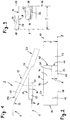
- Fig. 3 illustrates in a sectional view how piece goods, which may be wider than half the width or half the total channel width of the terminal 2, can be smoothly discharged on the upper conveyor channel and the lower conveyor channel of the sorting devices.
- Fig. 3 shows in the upper part of the illustration, a piece goods 60, which is on the second conveying surface 24 in abutment against the third side wall 26, wherein it protrudes laterally beyond the second conveying surface 24 and the side edge 28 due to its width.
- Fig. 3 in the lower part of the illustration, a piece goods 62 on the third conveying surface 36, wherein the width or the mutual distance of the fourth and fifth side walls 38,40 is greater than half the total channel width T.
- FIG. 3 also shows that the side edge 28 of the second conveying surface 24 is vertically above the fourth side wall 38 of the third conveying surface 36.
- the top view according Fig. 2 also clearly shows the width ratios of the first conveying surface 16, the second conveying surface 24 and the third conveying surface 36, as well as the Abierkanals 52 with the fourth conveying surface 54th
- Fig. 7 to 9 illustrate a second embodiment in which, in contrast to the embodiment described above, the second conveying surface 24 'and a portion 16' of the first conveying surface 16 are not perpendicular to the vertical planes 8, 10, but starting from the first conveying surface 16 and the thus defined plane are arranged sloping in the direction of the first vertical plane 8.
- Fig. 9 shows by way of example an arrangement in which the second conveying surface 24 'and the portion 16' of the first conveying surface at an angle of approximately 15 ° with respect to the first conveying surface 16 sloping in the direction of the first vertical plane 8.
- first side wall 18 'and the third side wall 26' can be arranged at an angle to the first vertical plane 8, so that they run at right angles to the inclined second conveying surface 24 'and the partial region 16' of the first conveying surface 16.
- Fig. 9 shows, general cargo, which are often cuboid, then promoted particularly favorable.
Landscapes
- Engineering & Computer Science (AREA)
- Mechanical Engineering (AREA)
- Branching, Merging, And Special Transfer Between Conveyors (AREA)
- Attitude Control For Articles On Conveyors (AREA)
- Discharge Of Articles From Conveyors (AREA)
Abstract
Description
- Die Erfindung betrifft eine Vorrichtung zum Zusammenführen von zwei in unterschiedlichen Höhen oder auch vertikal übereinander angeordneten Stückgutströmen, mit einem oberen Förderkanal zur Übernahme von Stückgutteilen von einem oberen Stückgutstrom und einem unteren Förderkanal zur Übernahme von Stückgutteilen von einem unteren Stückgutstrom. In einer bevorzugten Ausführung kann es sich bei der Vorrichtung zum Zusammenführen um eine Endstelle handeln und bei den Stückgutströmen um Fördervorrichtungen oder Sortiervorrichtungen, wobei eine mit einer derartigen Endstelle versehene Sortieranlage aus mindestens einer oberen Sortiervorrichtung und einer unteren Sortiervorrichtung besteht. Bevorzugt weisen die Sortiervorrichtungen Förderrichtungen auf, die einander entgegengesetzt sind. Denkbar wäre auch, dass die Förderrichtungen übereinstimmen.
- Bei einer derartigen Vorrichtung, deren Förderkanäle sich zwischen einer ersten Vertikalebene und einer parallelen zweiten Vertikalebene erstrecken, deren gegenseitiger Abstand einer Gesamtkanalbreite der Vorrichtung entspricht, besteht die Schwierigkeit, die Förderkanäle in einer günstigen Weise zusammenzuführen, um die Stückgutteile von den Stückgutströmen stromab bis zu einem Abförderkanal zu leiten. Bei einer bekannten Ausführung werden die Förderkanäle nebeneinander zusammengeführt, wobei jeder Förderkanal eine Breite aufweist, die der Hälfte der Gesamtkanalbreite entspricht. Bei einer solchen Ausführung kann es relativ leicht vorkommen, dass sich Stückgutteile, deren größte Abmessung größer als die Hälfte der Gesamtkanalbreite ist, im Zuge der Ausschleusung in einem Förderkanal verklemmen, was zu erheblichen Betriebsstörungen führen kann.
- Die Aufgabe der Erfindung besteht darin, eine Vorrichtung zum Zusammenführen von mindestens zwei in unterschiedlichen Höhen oder übereinander angeordnete Stückgutströme bereitzustellen, bei der die Gefahr einer Verklemmung von Stückgutteilen in einem Förderkanal reduziert ist.
- Diese Aufgabe wird erfindungsgemäß durch eine Vorrichtung zum Zusammenführen von mindestens zwei in unterschiedlichen Höhen angeordnete Stückgutströmen gelöst, mit einem oberen Förderkanal zur Übernahme von Stückgutteilen von einem oberen Stückgutstrom, und einem unteren Förderkanal zur Übernahme von Stückgutteilen von einem unteren Stückgutstrom, wobei sich die Förderkanäle zwischen einer ersten Vertikalebene und einer parallelen zweiten Vertikalebene, deren gegenseitiger Abstand einer Gesamtkanalbreite entspricht, erstrecken, wobei der obere Förderkanal eine erste Förderfläche zwischen einer ersten, in der ersten Vertikalebene verlaufenden Seitenwand und einer zweiten Seitenwand aufweist, wobei die zweite Seitenwand zumindest an einem stromaufseitigen, in Richtung des ersten Stückgutstroms weisenden, Endabschnitt in der zweiten Vertikalebene verläuft, und eine zweite Förderfläche, die sich angrenzend an eine in der ersten Vertikalebene verlaufende dritte Seitenwand stromab, von dem zweiten Stückgutstrom weg weisend, an die erste Förderfläche anschließt und eine Breite aufweist, die kleiner als die Hälfte der Gesamtkanalbreite ist, wobei die zweite Förderfläche an einem parallel zur ersten Vertikalebene verlaufenden Seitenrand in einem vertikalen Abstand oberhalb des unteren Förderkanals frei endet, wobei der untere Förderkanal eine dritte Förderfläche aufweist, die von einer in der zweiten Vertikalebene verlaufenden vierten Seitenwand und einer fünften Seitenwand begrenzt ist, wobei eine Breite der dritten Förderfläche an einem stromabseitigen Ende des unteren Förderkanals der Gesamtkanalbreite abzüglich der Breite der zweiten Förderfläche entspricht. Stromabseitige Enden der zweiten Förderfläche und der dritten Förderfläche können an einen Abförderkanal anschließen, der sich zur Übernahme von Stückgutteilen von dem oberen und dem unteren Förderkanal zwischen den Vertikalebenen erstreckt.
- Die zweite Förderfläche schließt bevorzugt lückenlos und mit bezogen auf die erste Förderfläche gleich großem, größerem oder kleinerem Gefälle an die erste Förderfläche an. Die Breite der zweiten Förderfläche ist bevorzugt über ihre Länge konstant.
- Obwohl die zweite Förderfläche eine geringere Breite als die Hälfte der Gesamtkanalbreite aufweist, können darauf Stückgutteile gefördert werden, deren Breite größer als die der zweiten Förderfläche ist und die bis zu einem der Gesamtkanalbreite entsprechenden Maß betragen kann, da die zweite Förderfläche an ihrem mit Abstand oder parallel zur ersten Vertikalebene verlaufenden Seitenrand frei endet und größere Stückgutteile über diesen Seitenrand überstehen können. Da der untere Förderkanal bzw. die dritte Förderfläche eine Breite besitzt, die größer als die halbe Gesamtkanalbreite ist, können auch in diesem Kanal Stückgutteile transportiert werden, deren Breite größer als die halbe Gesamtkanalbreite ist, so dass einem Verklemmen effektiv entgegengewirkt wird.
- Die zweite Seitenwand kann vollständig in der zweiten Vertikalebene verlaufen, wobei vorgesehen sein kann, dass die erste Förderfläche einen zwischen der zweiten Seitenwand und dem Seitenrand der zweiten Förderfläche angeordneten stromabseitigen Endabschnitt aufweist, der in einem vertikalen Abstand oberhalb des unteren Förderkanals bzw. der dritten Förderfläche angeordnet ist. Stückgutteile, die in einzelnen Fällen trotz ihrer ursprünglichen, in den Stückgutströmen herrschenden Fördergeschwindigkeit beim Abgabevorgang nicht gegen die erste Seitenwand und auf die zweite Förderfläche gelangen, können dann von dem stromabseitigen Endabschnitt der ersten Förderfläche auf den unteren Förderkanal bzw. auf die dritte Förderfläche fallen. Alternativ besteht die Möglichkeit, dass die zweite Seitenwand spitzwinklig zu der zweiten Vertikalebene verläuft und sich ausgehend von der zweiten Vertikalebene in Richtung der zweiten Förderfläche erstreckt. Diese Variante hat den Vorteil, dass die ankommenden Stückgutteile in jedem Fall auf die zweite Förderfläche geleitet werden, wobei jedoch u.U. eine gewisse Möglichkeit des Verklemmens einzelner Teile besteht.
- Die erste Förderfläche kann einen zwischen der zweiten Seitenwand und dem Seitenrand angeordneten stromabseitigen Endabschnitt aufweisen, der in einem vertikalen Abstand oberhalb des unteren Förderkanals bzw. der dritten Förderfläche angeordnet ist.
- Die fünfte Seitenwand kann von einer in der ersten Vertikalebene befindlichen Anfangsposition bis zu einer vertikal unter dem Seitenrand der zweiten Förderfläche befindlichen Endposition verlaufen, etwa geradlinig oder bogenförmig. Die fünfte Seitenwand kann einen spitzwinklig zu der ersten Vertikalebene verlaufenden Übergangsabschnitt und einen daran anschließenden, parallel zu der ersten Vertikalebene verlaufenden Führungsabschnitt aufweisen, dessen Abstand von der ersten Vertikalebene der Breite der zweiten Förderfläche entspricht.
- Es kann vorgesehen sein, dass die erste Förderfläche horizontal, d.h. senkrecht zu der ersten und zweiten Vertikalebene angeordnet ist. Weiter kann vorgesehen sein, dass die zweite Förderfläche entweder senkrecht zu der ersten Vertikalebene oder unter einem Winkel zu der ersten Vertikalebene oder dritten Seitenwand schräg abfallend angeordnet ist. Entsprechend besteht die Möglichkeit, dass ein Teilbereich der ersten Förderfläche, der ausgehend von der ersten Vertikalebene oder ersten Seitenwand eine gleiche Breite wie die zweite Förderfläche aufweist, entweder senkrecht zu der ersten Vertikalebene oder ersten Seitenwand oder aber unter einem Winkel schräg zu der ersten Vertikalebene oder ersten Seitenwand abfallend angeordnet ist. Der genannte Winkel kann beispielsweise zwischen 5° und 30° betragen, so dass eine Art Förderrinne für Stückgutteile gebildet ist.
- Zweckmäßigerweise ist vorgesehen, dass die untere Förderfläche senkrecht zu den Vertikalebenen angeordnet ist.
- Der Abförderkanal weist bevorzugt eine horizontal oder senkrecht zu den Vertikalebenen verlaufende vierte Förderfläche auf.
- Ein stromabseitiger Endabschnitt der zweiten Förderfläche ist bevorzugt in gleicher Höhe wie ein stromabseitiger Endabschnitt der dritten Förderfläche angeordnet, um einen problemlosen Übergang der Stückgutteile an den Abförderkanal bzw. die vierte Förderfläche zu gewährleisten. Zweckmäßigerweise befinden sich die beiden Endabschnitte an einer gleichen Längsposition, damit die vierte Förderfläche lückenlos an die zweite und dritte Förderfläche anschließen kann.
- Die erste Förderfläche und/oder, soweit vorhanden, der Teilbereich der ersten Förderfläche und/oder die zweite Förderfläche und/oder die dritte untere Förderfläche und/oder die vierte Förderfläche können jeweils als Gleitfläche, Gleitblech oder Rutsche, angetriebene oder passive Rollenbahn oder Band- oder Riemenförderer ausgebildet sein.
- Bevorzugt ist vorgesehen, dass die erste Förderfläche, soweit vorhanden der Teilbereich der ersten Förderfläche und die zweite Förderfläche ein Gefälle aufweisen. Die dritte Förderfläche kann ein Gefälle aufweisen oder horizontal angeordnet sein.
- Der Vorrichtung zum Zusammenführen von Stückgutströmen kann mindestens eine obere Sortiervorrichtung und mindestens eine untere Sortiervorrichtung zugeordnet sein, wobei die Stückgutströme als Sortiervorrichtungen ausgebildet sind und wobei sich die Sortiervorrichtungen vertikal übereinander oder in einem horizontalen Abstand voneinander befinden können. Die Sortiervorrichtungen können als Quergurt-Sorter ausgebildet sein.
- Es kann vorgesehen sein, dass die Sortiervorrichtungen in gleichen oder entgegengesetzten Förderrichtungen betreibbar sind.
- Zweckmäßigerweise ist vorgesehen, dass die Vertikalebenen senkrecht zu den Förderrichtungen angeordnet sind.
- Die Erfindung wird nachfolgend anhand von Ausführungsbeispielen erläutert, wobei auf eine Zeichnung Bezug genommen ist, in der
- Fig. 1
- eine schematische Seitenansicht einer erfindungsgemäßen Vorrichtung in Form einer Endstelle benachbart zu einer oberen und einer unteren Sortiervorrichtung zeigt,
- Fig.2
- eine Draufsicht auf die Vorrichtung zeigt,
- Fig. 3
- eine Schnittansicht entlang Linie III-III in
Fig. 1 zeigt, - Fig. 4 bis 6
- perspektivische Ansichten der Vorrichtung aus unterschiedlichen Richtungen zeigen,
- Fig. 7
- eine perspektivische Ansicht ähnlich
Fig. 4 einer alternativen Ausführungsform zeigt, - Fig. 8
- eine weitere perspektivische Ansicht der Ausführungsform nach
Fig. 7 zeigt, und - Fig. 9
- eine Schnittansicht entlang Linie IX-IX in
Fig. 8 zeigt, wobei zusätzlich Stückgutteile dargestellt sind. - Zunächst wird eine erste Ausführungsform der Erfindung anhand
Fig. 1 bis 6 erläutert. Die erfindungsgemäße Vorrichtung in Form einer Endstelle 2 dient der Übernahme von Stückgutteilen von mindestens zwei in unterschiedlichen Höhen oder auch vertikal übereinander angeordneten Stückgutströmen, die inFig. 1 mit 4 und 6 bezeichnet und beispielhaft als Sortiervorrichtungen ausgebildet sind. Anstelle einer oder beider Sortiervorrichtungen könnte jegliche Fördertechnik oder Vorrichtung zur Erzeugung von Stückgutströmen vorhanden sein, mit der einzelne Stückgutteile in zwei Bahnen herangefördert werden, die zu einem einzigen Fördergutstrom vereinigt werden sollen. In der dargestellten Ausführungsform ist eine obere Sortiervorrichtung 4 vertikal über einer unteren Sortiervorrichtung 6 angeordnet, deren Förderrichtungen horizontal, senkrecht zur Zeichenebene, verlaufen. Die Sortiervorrichtungen können bspw. als Quergurtsorter ausgebildet sein, wobei sich auf jeweils einem Fahrwagen oder Sorterelement eine quer zur Förderrichtung antreibbare Lastaufnahmeeinrichtung befindet, mit der einzelne Stückgutteile an der Endstelle 2 horizontal und quer zur Förderrichtung abgegeben werden können. In der Regel sind eine Vielzahl von Endstellen in Förderrichtung gesehen hintereinander benachbart zu den Sortiervorrichtungen angeordnet, wobei der Sortiervorgang durch Auswahl einer bestimmten Endstelle erfolgt. Jeweils eine Endstelle und insbesondere die inFig. 1 dargestellte Endstelle befindet sich zwischen zwei beabstandeten Vertikalebenen, einer ersten Vertikalebene 8 und einer in einem Abstand T, der auch als Gesamtkanalbreite der Endstelle bezeichnet wird, davon befindlichen zweiten Vertikalebene 10. Die Vertikalebenen 8,10 sind bevorzugt senkrecht zu den Förderrichtungen der Sortiervorrichtungen 4, 6 angeordnet. - Der grundsätzliche Aufbau der Endstelle 2 wird am besten aus den perspektivischen Ansichten gemäß
Fig. 4 bis 6 deutlich. Die Endstelle 2 besitzt einen oberen Förderkanal 12 zur Übernahme von Stückgutteilen von der oberen Sortiervorrichtung 4 und einem unteren Förderkanal 14 zur Übernahme von Stückgutteilen von der unteren Sortiervorrichtung 6. Der obere Förderkanal 12 weist eine erste Förderfläche 16 auf, die von einer in der ersten Vertikalebene 8 verlaufenden ersten Seitenwand 18 und von einer in der zweiten Vertikalebene 10 verlaufenden zweiten Seitenwand 20 begrenzt ist. Weiterhin weist der obere Förderkanal 12 anschließend an die erste Förderfläche 16 eine zweite Förderfläche 24 auf, die von einer in der ersten Vertikalebene 8 verlaufenden dritten Seitenwand 26 begrenzt ist. Die dritte Seitenwand 26 kann sich unmittelbar an die erste Seitenwand 18 anschließen. Die zweite Förderfläche 24 weist einen Seitenrand 28 auf, an dem sie frei endet. Der Seitenrand 28 verläuft parallel zur ersten Verbindungsebene 8 und weist einen Abstand a davon auf, der einer Breite der zweiten Förderfläche 24 entspricht und kleiner ist als die Hälfte der Gesamtkanalbreite T. Die erste Förderfläche 16 hat eine Breite, die der Gesamtkanalbreite T entspricht und weist zwischen der zweiten Seitenwand 20 und dem Seitenrand 28 der zweiten Förderfläche 24 einen stromabseitigen Endabschnitt 30 auf, der in einem vertikalen Abstand oberhalb des unteren Förderkanals 14 endet. - Die erste Seitenwand 18 und die zweite Seitenwand 20 enden mit stromaufseitigen Endabschnitten 18a, 20a jeweils in einem Abstand von einem stromaufseitigen Endabschnitt 32 der ersten Förderfläche 16, um zu ermöglichen, dass von der oberen Sortiervorrichtung 4 quer zur Förderrichtung abgegebene Stückgutteile eine gebogene Trajektorie durchlaufen können, was bei höheren Förder- und Abgabegeschwindigkeiten zweckmäßig ist.
- Der stromaufseitige Endabschnitt 32 der ersten Förderfläche 16 ist bei Verwendung der Endstelle unmittelbar benachbart zu der oberen Sortiervorrichtung 6 angeordnet, wie die Seitenansicht nach
Fig. 1 zeigt. - Der untere Förderkanal 14 weist eine dritte Förderfläche 36 auf, die von einer in der zweiten Vertikalebene 10 verlaufenden vierten Seitenwand 38 und einer fünften Seitenwand 40 begrenzt ist. Die fünfte Seitenwand 40 verläuft von einer in der ersten Vertikalebene 8 befindlichen Anfangsposition bis zu einer vertikal unter dem Seitenrand 28 der zweiten Förderfläche 24 befindlichen Endposition, wobei sie einen spitzwinklig zu der ersten Vertikalebene 8 verlaufenden Übergangsabschnitt 42 und einen daran anschließenden, parallel zu der ersten Vertikalebene 8 verlaufenden Führungsabschnitt 44 aufweist, dessen Abstand von der ersten Vertikalebene der Breite der zweiten Förderfläche 24 entspricht. Die vierte Seitenwand 38 und die fünfte Seitenwand 40 beginnen in einem Abstand von einem stromaufseitigen Endabschnitt 46 der dritten Förderfläche 36, der sich benachbart zu der unteren Sortiervorrichtung 6 befindet, wie auch
Fig. 1 zeigt, um, wie vorstehend im Hinblick auf die erste und zweite Seitenwand der ersten Förderfläche 16 erläutert, eine günstige Übergabe der Stückgutteile zu ermöglichen. - Ein stromabseitiger Endabschnitt 48 der dritten Förderfläche 36 befindet sich in gleicher Höhe und unmittelbar benachbart zu einem stromabseitigen Endabschnitt 50 der zweiten Förderfläche 24, wobei sich ein Abförderkanal 52 mit einer vierten Förderfläche 54 an die zweite Förderfläche 24 und die dritte Förderfläche 36 bzw. deren stromabseitige Endabschnitte 48, 50 anschließt. Die vierte Förderfläche 54 erstreckt sich über die volle Breite oder die Gesamtkanalbreite T der Endstelle 2, zwischen den Vertikalebenen 8,10 und zwischen in diesen verlaufenden Seitenwänden, die sich lückenlos an die dritten und vierten Seitenwände 26, 38 der zweiten und dritten Förderflächen 24, 36 anschließen können.
-
Fig. 3 erläutert in einer Schnittansicht, wie Stückgutteile, die breiter als die halbe Breite oder die halbe Gesamtkanalbreite der Endstelle 2 sein können, störungsfrei auf dem oberen Förderkanal und dem unteren Förderkanal von den Sortiervorrichtungen ausgeschleust werden können.Fig. 3 zeigt im oberen Teil der Darstellung ein Stückgutteil 60, das sich auf der zweiten Förderfläche 24 in Anlage gegen die dritte Seitenwand 26 befindet, wobei es aufgrund seiner Breite seitlich über die zweite Förderfläche 24 und deren Seitenrand 28 übersteht. Entsprechend zeigtFig. 3 im unteren Teil der Darstellung ein Stückgutteil 62 auf der dritten Förderfläche 36, wobei deren Breite bzw. der gegenseitige Abstand der vierten und fünften Seitenwände 38,40 größer als die halbe Gesamtkanalbreite T ist.Fig. 3 zeigt auch, dass sich der Seitenrand 28 der zweiten Förderfläche 24 vertikal über der vierten Seitenwand 38 der dritten Förderfläche 36 befindet. Die Draufsicht gemäßFig. 2 zeigt ebenfalls deutlich die Breitenverhältnisse der ersten Förderfläche 16, der zweiten Förderfläche 24 und der dritten Förderfläche 36, sowie des Abförderkanals 52 mit der vierten Förderfläche 54. -
Fig. 7 bis 9 erläutern eine zweite Ausführungsform, bei der im Unterschied zur vorstehend beschriebenen Ausführungsform die zweite Förderfläche 24' und ein Teilbereich 16' der ersten Förderfläche 16 nicht senkrecht zu den Vertikalebenen 8, 10 verlaufen, sondern ausgehend von der ersten Förderfläche 16 bzw. der dadurch festgelegten Ebene schräg abfallend in Richtung der ersten Vertikalebene 8 angeordnet sind.Fig. 9 zeigt beispielhaft eine Anordnung, bei der die zweite Förderfläche 24' und der Teilbereich 16' der ersten Förderfläche unter einem Winkel von ca. 15° gegenüber der ersten Förderfläche 16 abfallend in Richtung der ersten Vertikalebene 8 verlaufen. Weiterhin zeigenFig. 7 bis 9 , dass auch die erste Seitenwand 18' und die dritte Seitenwand 26' unter einem Winkel zur ersten Vertikalebene 8 angeordnet sein können, so dass sie rechtwinklig zur schräg verlaufenden zweiten Förderfläche 24' und dem Teilbereich 16' der ersten Förderfläche 16 verlaufen. WieFig. 9 zeigt, können Stückgutteile, die häufig quaderförmig sind, dann besonders günstig gefördert werden. -
- 2
- Endstelle (Vorrichtung)
- 4
- obere Sortiervorrichtung (Stückgutstrom)
- 6
- untere Sortiervorrichtung (Stückgutstrom)
- 8
- erste Vertikalebene
- 10
- zweite Vertikalebene
- 12
- oberer Förderkanal
- 14
- unterer Förderkanal
- 16
- erste Förderfläche
- 16'
- Teilbereich (von 16)
- 18, 18'
- erste Seitenwand
- 18a
- stromaufseitiger Endabschnitt
- 20
- zweite Seitenwand
- 20a
- stromaufseitiger Endabschnitt
- 24, 24'
- zweite Förderfläche
- 26, 26'
- dritte Seitenwand
- 28
- Seitenrand
- 30
- stromabseitiger Endabschnitt (von 16)
- 32
- stromaufseitiger Endabschnitt (von 16)
- 36
- dritte Förderfläche
- 38
- vierte Seitenwand
- 40
- fünfte Seitenwand
- 42
- Übergangsabschnitt
- 44
- Führungsabschnitt
- 46
- stromaufseitiger Endabschnitt (von 36)
- 48
- stromabseitiger Endabschnitt (von 36)
- 50
- stromabseitiger Endabschnitt (von 24)
- 52
- Abförderkanal
- 54
- vierte Förderfläche
- 60, 62
- Stückgutteil
- a
- Abstand
- T
- Gesamtkanalbreite (Teilungsmaß der Endstelle)
Claims (15)
- Vorrichtung (2) zum Zusammenführen von mindestens zwei in unterschiedlichen Höhen angeordneten Stückgutströmen (4,6), mit einem oberen Förderkanal (12) zur Übernahme von Stückgutteilen (60) von einem oberen Stückgutstrom (4), und einem unteren Förderkanal (14) zur Übernahme von Stückgutteilen (62) von einem unteren Stückgutstrom (6), wobei sich die Förderkanäle (12, 14) zwischen einer ersten Vertikalebene (8) und einer parallelen zweiten Vertikalebene (10), deren gegenseitiger Abstand einer Gesamtkanalbreite (T) der Endstelle entspricht, erstrecken, wobei der obere Förderkanal (12) eine erste Förderfläche (16) zwischen einer ersten, in der ersten Vertikalebene (8) verlaufenden Seitenwand (18) und einer zweiten Seitenwand (20) aufweist, wobei die zweite Seitenwand (20) zumindest an einem stromaufseitigen Endabschnitt (20a) in der zweiten Vertikalebene (10) verläuft, und eine zweite Förderfläche (18), die sich angrenzend an eine in der ersten Vertikalebene (8) verlaufende dritte Seitenwand (26) stromab an die erste Förderfläche (16) anschließt und eine Breite aufweist, die kleiner als die Hälfte des Gesamtkanalbreite (T) ist, wobei die zweite Förderfläche (24) an einem parallel zur ersten Vertikalebene (8) verlaufenden Seitenrand (28) in einem vertikalen Abstand oberhalb des unteren Förderkanals (14) frei endet, wobei der untere Förderkanal (14) eine dritte Förderfläche (36) aufweist, die von einer in der zweiten Vertikalebene (10) verlaufenden vierten Seitenwand (38) und einer fünften Seitenwand (40) begrenzt ist, wobei eine Breite der dritten Förderfläche (36) an einem stromabseitigen Ende (30) des unteren Förderkanals (14) der Gesamtkanalbreite (T) abzüglich der Breite der zweiten Förderfläche (24) entspricht.
- Vorrichtung (2) nach Anspruch 1, dadurch gekennzeichnet, dass die zweite Seitenwand (20) vollständig in der zweiten Vertikalebene (10) verläuft.
- Vorrichtung (2) nach Anspruch 1, dadurch gekennzeichnet, dass die zweite Seitenwand (20) spitzwinklig zu der zweiten Vertikalebene (10) verläuft und sich ausgehend von der zweiten Vertikalebene (10) in Richtung der zweiten Förderfläche (24) erstrecken kann.
- Vorrichtung (2) nach einem der vorangehenden Ansprüche, dadurch gekennzeichnet, dass die erste Förderfläche (16) einen zwischen der zweiten Seitenwand (20) und dem Seitenrand (28) angeordneten stromabseitigen Endabschnitt (30) aufweist, der in einem vertikalen Abstand oberhalb des unteren Förderkanals (14) angeordnet ist.
- Vorrichtung (2) nach einem der vorangehenden Ansprüche, dadurch gekennzeichnet, dass die fünfte Seitenwand (40) von einer in der ersten Vertikalebene (8) befindlichen Anfangsposition bis zu einer vertikal unter dem Seitenrand (28) der zweiten Förderfläche (24) befindlichen Endposition verläuft.
- Vorrichtung (2) nach einem der vorangehenden Ansprüche, dadurch gekennzeichnet, dass die fünfte Seitenwand (40) einen spitzwinklig zu der ersten Vertikalebene (8) verlaufenden Übergangsabschnitt (42) und einen anschließenden parallel zu der ersten Vertikalebene (8) verlaufenden Führungsabschnitt (44) aufweist, dessen Abstand von der ersten Vertikalebene (8) der Breite der zweiten Förderfläche (24) entspricht.
- Vorrichtung (2) nach einem der vorangehenden Ansprüche, dadurch gekennzeichnet, dass die erste Förderfläche (16) senkrecht zu der ersten und zweiten Vertikalebene (8, 10) angeordnet ist.
- Vorrichtung (2) nach einem der vorangehenden Ansprüche, dadurch gekennzeichnet, dass die zweite Förderfläche (24) senkrecht zu der ersten Vertikalebene (8) oder unter einem Winkel zu der ersten Vertikalebene (8) schräg abfallend angeordnet ist.
- Vorrichtung (2) nach Anspruch 8, dadurch gekennzeichnet, dass ein Teilbereich (16') der ersten Förderfläche (16), der ausgehend von der ersten Vertikalebene (8) eine gleiche Breite wie die zweite Förderfläche (24) aufweist, entweder senkrecht zu der ersten Vertikalebene (8) oder unter einem Winkel zu der ersten Vertikalebene (8) schräg abfallend angeordnet ist.
- Vorrichtung (2) nach einem der vorangehenden Ansprüche, dadurch gekennzeichnet, dass die dritte Förderfläche (36) senkrecht zu den Vertikalebenen (8, 10) angeordnet ist.
- Vorrichtung (2) nach einem der vorangehenden Ansprüche, dadurch gekennzeichnet, dass ein stromabseitiger Endabschnitt (50) der zweiten Förderfläche (24) in gleicher Höhe wie ein stromabseitiger Endabschnitt (48) der dritten Förderfläche (36) angeordnet ist.
- Vorrichtung (2) nach einem der vorangehenden Ansprüche, dadurch gekennzeichnet, dass der Abförderkanal (52) eine senkrecht zu den Vertikalebenen (8, 10) verlaufende vierte Förderfläche (54) aufweist.
- Vorrichtung (2) nach einem der vorangehenden Ansprüche, dadurch gekennzeichnet, dass die erste Förderfläche (16) und/oder soweit vorhanden, der Teilbereich (16') der ersten Förderfläche (16) und/oder die zweite Förderfläche (24) und/oder die dritte Förderfläche (36) und/oder die vierte Förderfläche (54) jeweils als Gleitfläche, Gleitblech, Rutsche, angetriebene oder passive Rollenbahn oder Band- oder Riemenförderer ausgebildet ist.
- Vorrichtung (2) nach einem der vorangehenden Ansprüche, dadurch gekennzeichnet, dass die erste Förderfläche (16), soweit vorhanden der Teilbereich (16') der ersten Förderfläche (16) und die zweite Förderfläche (24) ein Gefälle aufweisen.
- Vorrichtung (2) nach einem der vorangehenden Ansprüche, dadurch gekennzeichnet, dass der Vorrichtung (2) eine obere Sortiervorrichtung (4) und eine untere Sortiervorrichtung (6) zugeordnet ist und die Vorrichtung (2) als Endstelle ausgebildet ist.
Priority Applications (3)
| Application Number | Priority Date | Filing Date | Title |
|---|---|---|---|
| PL17207274T PL3498639T3 (pl) | 2017-12-14 | 2017-12-14 | Urządzenie do łączenia dwóch strumieni drobnicy usytuowanych na różnych wysokościach |
| EP17207274.6A EP3498639B1 (de) | 2017-12-14 | 2017-12-14 | Vorrichtung zum zusammenführen von zwei in unterschiedlichen höhen angeordneten stückgutströmen |
| US16/201,466 US10377570B2 (en) | 2017-12-14 | 2018-11-27 | Device for merging two piece goods streams arranged at different heights |
Applications Claiming Priority (1)
| Application Number | Priority Date | Filing Date | Title |
|---|---|---|---|
| EP17207274.6A EP3498639B1 (de) | 2017-12-14 | 2017-12-14 | Vorrichtung zum zusammenführen von zwei in unterschiedlichen höhen angeordneten stückgutströmen |
Publications (2)
| Publication Number | Publication Date |
|---|---|
| EP3498639A1 true EP3498639A1 (de) | 2019-06-19 |
| EP3498639B1 EP3498639B1 (de) | 2020-05-20 |
Family
ID=60781532
Family Applications (1)
| Application Number | Title | Priority Date | Filing Date |
|---|---|---|---|
| EP17207274.6A Active EP3498639B1 (de) | 2017-12-14 | 2017-12-14 | Vorrichtung zum zusammenführen von zwei in unterschiedlichen höhen angeordneten stückgutströmen |
Country Status (3)
| Country | Link |
|---|---|
| US (1) | US10377570B2 (de) |
| EP (1) | EP3498639B1 (de) |
| PL (1) | PL3498639T3 (de) |
Cited By (1)
| Publication number | Priority date | Publication date | Assignee | Title |
|---|---|---|---|---|
| WO2022253452A1 (de) * | 2021-05-31 | 2022-12-08 | Körber Supply Chain Logistics Gmbh | Verjüngung eines förderstroms von stückgütern |
Families Citing this family (2)
| Publication number | Priority date | Publication date | Assignee | Title |
|---|---|---|---|---|
| JP6629380B2 (ja) * | 2018-04-11 | 2020-01-15 | セキ工業株式会社 | 部品整送装置 |
| CN114453323B (zh) * | 2022-03-11 | 2023-05-16 | 南京享利达模具有限公司 | 自动进料带烘干干压水清洗机 |
Citations (5)
| Publication number | Priority date | Publication date | Assignee | Title |
|---|---|---|---|---|
| GB1448744A (en) * | 1973-11-05 | 1976-09-08 | Danepak Ltd | Conveyors |
| US4645061A (en) * | 1985-02-26 | 1987-02-24 | Welch Hubert E | Machine for stacking nestable extruded cans |
| US5361889A (en) * | 1993-09-17 | 1994-11-08 | Brown & Williamson Tobacco Corporation | Apparatus for merging multiple lanes of product |
| FR2832654A1 (fr) * | 2001-11-23 | 2003-05-30 | Chronopost | Dispositif pour le tri de colis par separation morphologique |
| US20060088404A1 (en) * | 2004-10-26 | 2006-04-27 | Lafontaine Daniel R | Automated order mixing system |
Family Cites Families (12)
| Publication number | Priority date | Publication date | Assignee | Title |
|---|---|---|---|---|
| US1969276A (en) * | 1930-10-24 | 1934-08-07 | Pevear Chase Keith | Merchandise handling system |
| US3221857A (en) * | 1964-07-09 | 1965-12-07 | Holstein & Kappert Maschf | Apparatus for orienting bottle caps and the like |
| DE1975576U (de) * | 1967-08-28 | 1967-12-21 | Herkules Papiersackfabriken Br | Vorrichtung zur herstellung von saecken aus papier, kunststoff od. dgl. |
| US3612268A (en) * | 1970-04-15 | 1971-10-12 | Dynasort Corp | Silverware orienting means |
| US4033441A (en) * | 1975-06-16 | 1977-07-05 | Aluminum Company Of America | Merging or blending techniques for small parts |
| IT1285965B1 (it) * | 1996-06-25 | 1998-06-26 | Gd Spa | Unita' convogliatrice di prodotti |
| US7270227B2 (en) * | 2003-10-29 | 2007-09-18 | Lockheed Martin Corporation | Material handling system and method of use |
| DE102007001973B4 (de) * | 2007-01-13 | 2008-10-16 | Khs Ag | Vorrichtung zum Zusammenführen von Gebinden, wie Kleincontainern oder dergleichen |
| US9359150B2 (en) * | 2013-04-12 | 2016-06-07 | Axium Inc. | Singulator |
| DE102016109310A1 (de) * | 2016-05-20 | 2017-11-23 | Deutsche Post Ag | Rutsche und Sortiereinrichtung sowie Verfahren zum Sortieren von Stückgut |
| EP3381842B1 (de) * | 2017-03-27 | 2020-01-15 | BEUMER Group GmbH & Co. KG | Fördervorrichtung zum zusammenführen von stückgutteilen von mehreren einschleusförderern |
| US10549912B2 (en) * | 2017-09-27 | 2020-02-04 | Toyota Motor Engineering & Manufacturing North America, Inc. | Flow rack assemblies and methods of use |
-
2017
- 2017-12-14 PL PL17207274T patent/PL3498639T3/pl unknown
- 2017-12-14 EP EP17207274.6A patent/EP3498639B1/de active Active
-
2018
- 2018-11-27 US US16/201,466 patent/US10377570B2/en active Active
Patent Citations (5)
| Publication number | Priority date | Publication date | Assignee | Title |
|---|---|---|---|---|
| GB1448744A (en) * | 1973-11-05 | 1976-09-08 | Danepak Ltd | Conveyors |
| US4645061A (en) * | 1985-02-26 | 1987-02-24 | Welch Hubert E | Machine for stacking nestable extruded cans |
| US5361889A (en) * | 1993-09-17 | 1994-11-08 | Brown & Williamson Tobacco Corporation | Apparatus for merging multiple lanes of product |
| FR2832654A1 (fr) * | 2001-11-23 | 2003-05-30 | Chronopost | Dispositif pour le tri de colis par separation morphologique |
| US20060088404A1 (en) * | 2004-10-26 | 2006-04-27 | Lafontaine Daniel R | Automated order mixing system |
Cited By (1)
| Publication number | Priority date | Publication date | Assignee | Title |
|---|---|---|---|---|
| WO2022253452A1 (de) * | 2021-05-31 | 2022-12-08 | Körber Supply Chain Logistics Gmbh | Verjüngung eines förderstroms von stückgütern |
Also Published As
| Publication number | Publication date |
|---|---|
| US10377570B2 (en) | 2019-08-13 |
| EP3498639B1 (de) | 2020-05-20 |
| PL3498639T3 (pl) | 2020-11-16 |
| US20190185268A1 (en) | 2019-06-20 |
Similar Documents
| Publication | Publication Date | Title |
|---|---|---|
| EP0795497B1 (de) | Fördersystem für die Vereinzelung von Stückgut | |
| EP2088099B1 (de) | Fördereinrichtung zum vertikalen Transport von Stückgut | |
| EP3498639B1 (de) | Vorrichtung zum zusammenführen von zwei in unterschiedlichen höhen angeordneten stückgutströmen | |
| EP3381842B1 (de) | Fördervorrichtung zum zusammenführen von stückgutteilen von mehreren einschleusförderern | |
| DE3806168A1 (de) | Foerdereinrichtung fuer gegenstaende | |
| EP3251981A1 (de) | Laufwagen für ein schienengeführtes fördersystem, sowie fördersystem mit einem solchen laufwagen | |
| DE3926735A1 (de) | Verfahren und vorrichtung zum zufuehren von flaschen oder dgl. | |
| WO2008012214A1 (de) | Verteileinrichtung für stückgut | |
| EP2818436B1 (de) | Vorrichtung zum Vereinzeln von Stückgutteilen | |
| EP1655246B1 (de) | Vorrichtung und Verfahren zum Aufteilen eines Produktestroms mittels einer Rutsche | |
| WO2022129342A1 (de) | Behälterzuführvorrichtung und verfahren zum betreiben der behälterzuführvorrichtung | |
| DE10317417B4 (de) | Vereinzelungs- und Fördervorrichtung | |
| DE3715577A1 (de) | Verfahren und vorrichtung zum vereinzeln von flaschen | |
| EP0252461A1 (de) | Anordnung zum Umformen eines angeförderten mehrspurigen Flaschenstromes in einen abzufördernden einspurigen Flaschenstrom | |
| WO1999055609A1 (de) | Verfahren und vorrichtung zum weiterfördern von in einem schuppenstrom anfallenden flächigen gegenständen | |
| CH663604A5 (de) | Umlenkeinrichtung fuer einen schuppenstrom. | |
| EP3746383A1 (de) | Vorrichtung und verfahren zum fördern von stückgütern einer ersten und einer zweiten klasse hin zu einem sorter | |
| EP3533731A1 (de) | Schrägförderer | |
| DE4133588A1 (de) | Anordnung zum umformen eines angefoerderten mehrspurigen behaelterstromes in einen abzufoerdernden einspurigen behaelterstrom | |
| DE2315708A1 (de) | Vorrichtung zum trennen und ausrichten von ungeordnet auf ein endloses foerderband aufgebrachten, laenglichen gegenstaenden | |
| EP2039631B1 (de) | Separationsvorrichtung | |
| DE3820269A1 (de) | Baugruppe zum foerdern eines produktstromes von papierprodukten mit einem einzigen foerderbandpaarsystem | |
| WO2015189153A1 (de) | Transportsystem | |
| DE202015009814U1 (de) | Fördervorrichtung vom Typ der Entkonsolidierung | |
| DE3342064C2 (de) |
Legal Events
| Date | Code | Title | Description |
|---|---|---|---|
| PUAI | Public reference made under article 153(3) epc to a published international application that has entered the european phase |
Free format text: ORIGINAL CODE: 0009012 |
|
| STAA | Information on the status of an ep patent application or granted ep patent |
Free format text: STATUS: THE APPLICATION HAS BEEN PUBLISHED |
|
| AK | Designated contracting states |
Kind code of ref document: A1 Designated state(s): AL AT BE BG CH CY CZ DE DK EE ES FI FR GB GR HR HU IE IS IT LI LT LU LV MC MK MT NL NO PL PT RO RS SE SI SK SM TR |
|
| AX | Request for extension of the european patent |
Extension state: BA ME |
|
| STAA | Information on the status of an ep patent application or granted ep patent |
Free format text: STATUS: REQUEST FOR EXAMINATION WAS MADE |
|
| 17P | Request for examination filed |
Effective date: 20190704 |
|
| RBV | Designated contracting states (corrected) |
Designated state(s): AL AT BE BG CH CY CZ DE DK EE ES FI FR GB GR HR HU IE IS IT LI LT LU LV MC MK MT NL NO PL PT RO RS SE SI SK SM TR |
|
| GRAP | Despatch of communication of intention to grant a patent |
Free format text: ORIGINAL CODE: EPIDOSNIGR1 |
|
| RIC1 | Information provided on ipc code assigned before grant |
Ipc: B65G 47/68 20060101AFI20190821BHEP |
|
| STAA | Information on the status of an ep patent application or granted ep patent |
Free format text: STATUS: GRANT OF PATENT IS INTENDED |
|
| INTG | Intention to grant announced |
Effective date: 20190926 |
|
| GRAS | Grant fee paid |
Free format text: ORIGINAL CODE: EPIDOSNIGR3 |
|
| GRAA | (expected) grant |
Free format text: ORIGINAL CODE: 0009210 |
|
| STAA | Information on the status of an ep patent application or granted ep patent |
Free format text: STATUS: THE PATENT HAS BEEN GRANTED |
|
| AK | Designated contracting states |
Kind code of ref document: B1 Designated state(s): AL AT BE BG CH CY CZ DE DK EE ES FI FR GB GR HR HU IE IS IT LI LT LU LV MC MK MT NL NO PL PT RO RS SE SI SK SM TR |
|
| REG | Reference to a national code |
Ref country code: GB Ref legal event code: FG4D Free format text: NOT ENGLISH |
|
| REG | Reference to a national code |
Ref country code: CH Ref legal event code: EP |
|
| REG | Reference to a national code |
Ref country code: DE Ref legal event code: R096 Ref document number: 502017005373 Country of ref document: DE |
|
| REG | Reference to a national code |
Ref country code: AT Ref legal event code: REF Ref document number: 1272481 Country of ref document: AT Kind code of ref document: T Effective date: 20200615 |
|
| REG | Reference to a national code |
Ref country code: CH Ref legal event code: NV Representative=s name: NOVAGRAAF INTERNATIONAL SA, CH |
|
| REG | Reference to a national code |
Ref country code: LT Ref legal event code: MG4D |
|
| REG | Reference to a national code |
Ref country code: NL Ref legal event code: MP Effective date: 20200520 |
|
| PG25 | Lapsed in a contracting state [announced via postgrant information from national office to epo] |
Ref country code: IS Free format text: LAPSE BECAUSE OF FAILURE TO SUBMIT A TRANSLATION OF THE DESCRIPTION OR TO PAY THE FEE WITHIN THE PRESCRIBED TIME-LIMIT Effective date: 20200920 Ref country code: SE Free format text: LAPSE BECAUSE OF FAILURE TO SUBMIT A TRANSLATION OF THE DESCRIPTION OR TO PAY THE FEE WITHIN THE PRESCRIBED TIME-LIMIT Effective date: 20200520 Ref country code: NO Free format text: LAPSE BECAUSE OF FAILURE TO SUBMIT A TRANSLATION OF THE DESCRIPTION OR TO PAY THE FEE WITHIN THE PRESCRIBED TIME-LIMIT Effective date: 20200820 Ref country code: GR Free format text: LAPSE BECAUSE OF FAILURE TO SUBMIT A TRANSLATION OF THE DESCRIPTION OR TO PAY THE FEE WITHIN THE PRESCRIBED TIME-LIMIT Effective date: 20200821 Ref country code: FI Free format text: LAPSE BECAUSE OF FAILURE TO SUBMIT A TRANSLATION OF THE DESCRIPTION OR TO PAY THE FEE WITHIN THE PRESCRIBED TIME-LIMIT Effective date: 20200520 Ref country code: PT Free format text: LAPSE BECAUSE OF FAILURE TO SUBMIT A TRANSLATION OF THE DESCRIPTION OR TO PAY THE FEE WITHIN THE PRESCRIBED TIME-LIMIT Effective date: 20200921 Ref country code: LT Free format text: LAPSE BECAUSE OF FAILURE TO SUBMIT A TRANSLATION OF THE DESCRIPTION OR TO PAY THE FEE WITHIN THE PRESCRIBED TIME-LIMIT Effective date: 20200520 |
|
| PG25 | Lapsed in a contracting state [announced via postgrant information from national office to epo] |
Ref country code: LV Free format text: LAPSE BECAUSE OF FAILURE TO SUBMIT A TRANSLATION OF THE DESCRIPTION OR TO PAY THE FEE WITHIN THE PRESCRIBED TIME-LIMIT Effective date: 20200520 Ref country code: BG Free format text: LAPSE BECAUSE OF FAILURE TO SUBMIT A TRANSLATION OF THE DESCRIPTION OR TO PAY THE FEE WITHIN THE PRESCRIBED TIME-LIMIT Effective date: 20200820 Ref country code: RS Free format text: LAPSE BECAUSE OF FAILURE TO SUBMIT A TRANSLATION OF THE DESCRIPTION OR TO PAY THE FEE WITHIN THE PRESCRIBED TIME-LIMIT Effective date: 20200520 Ref country code: HR Free format text: LAPSE BECAUSE OF FAILURE TO SUBMIT A TRANSLATION OF THE DESCRIPTION OR TO PAY THE FEE WITHIN THE PRESCRIBED TIME-LIMIT Effective date: 20200520 |
|
| PG25 | Lapsed in a contracting state [announced via postgrant information from national office to epo] |
Ref country code: NL Free format text: LAPSE BECAUSE OF FAILURE TO SUBMIT A TRANSLATION OF THE DESCRIPTION OR TO PAY THE FEE WITHIN THE PRESCRIBED TIME-LIMIT Effective date: 20200520 Ref country code: AL Free format text: LAPSE BECAUSE OF FAILURE TO SUBMIT A TRANSLATION OF THE DESCRIPTION OR TO PAY THE FEE WITHIN THE PRESCRIBED TIME-LIMIT Effective date: 20200520 |
|
| PG25 | Lapsed in a contracting state [announced via postgrant information from national office to epo] |
Ref country code: SM Free format text: LAPSE BECAUSE OF FAILURE TO SUBMIT A TRANSLATION OF THE DESCRIPTION OR TO PAY THE FEE WITHIN THE PRESCRIBED TIME-LIMIT Effective date: 20200520 Ref country code: DK Free format text: LAPSE BECAUSE OF FAILURE TO SUBMIT A TRANSLATION OF THE DESCRIPTION OR TO PAY THE FEE WITHIN THE PRESCRIBED TIME-LIMIT Effective date: 20200520 Ref country code: EE Free format text: LAPSE BECAUSE OF FAILURE TO SUBMIT A TRANSLATION OF THE DESCRIPTION OR TO PAY THE FEE WITHIN THE PRESCRIBED TIME-LIMIT Effective date: 20200520 Ref country code: RO Free format text: LAPSE BECAUSE OF FAILURE TO SUBMIT A TRANSLATION OF THE DESCRIPTION OR TO PAY THE FEE WITHIN THE PRESCRIBED TIME-LIMIT Effective date: 20200520 Ref country code: CZ Free format text: LAPSE BECAUSE OF FAILURE TO SUBMIT A TRANSLATION OF THE DESCRIPTION OR TO PAY THE FEE WITHIN THE PRESCRIBED TIME-LIMIT Effective date: 20200520 Ref country code: ES Free format text: LAPSE BECAUSE OF FAILURE TO SUBMIT A TRANSLATION OF THE DESCRIPTION OR TO PAY THE FEE WITHIN THE PRESCRIBED TIME-LIMIT Effective date: 20200520 Ref country code: IT Free format text: LAPSE BECAUSE OF FAILURE TO SUBMIT A TRANSLATION OF THE DESCRIPTION OR TO PAY THE FEE WITHIN THE PRESCRIBED TIME-LIMIT Effective date: 20200520 |
|
| REG | Reference to a national code |
Ref country code: DE Ref legal event code: R097 Ref document number: 502017005373 Country of ref document: DE |
|
| PG25 | Lapsed in a contracting state [announced via postgrant information from national office to epo] |
Ref country code: SK Free format text: LAPSE BECAUSE OF FAILURE TO SUBMIT A TRANSLATION OF THE DESCRIPTION OR TO PAY THE FEE WITHIN THE PRESCRIBED TIME-LIMIT Effective date: 20200520 |
|
| PLBE | No opposition filed within time limit |
Free format text: ORIGINAL CODE: 0009261 |
|
| STAA | Information on the status of an ep patent application or granted ep patent |
Free format text: STATUS: NO OPPOSITION FILED WITHIN TIME LIMIT |
|
| 26N | No opposition filed |
Effective date: 20210223 |
|
| PG25 | Lapsed in a contracting state [announced via postgrant information from national office to epo] |
Ref country code: SI Free format text: LAPSE BECAUSE OF FAILURE TO SUBMIT A TRANSLATION OF THE DESCRIPTION OR TO PAY THE FEE WITHIN THE PRESCRIBED TIME-LIMIT Effective date: 20200520 |
|
| PG25 | Lapsed in a contracting state [announced via postgrant information from national office to epo] |
Ref country code: MC Free format text: LAPSE BECAUSE OF FAILURE TO SUBMIT A TRANSLATION OF THE DESCRIPTION OR TO PAY THE FEE WITHIN THE PRESCRIBED TIME-LIMIT Effective date: 20200520 |
|
| REG | Reference to a national code |
Ref country code: BE Ref legal event code: MM Effective date: 20201231 |
|
| PG25 | Lapsed in a contracting state [announced via postgrant information from national office to epo] |
Ref country code: LU Free format text: LAPSE BECAUSE OF NON-PAYMENT OF DUE FEES Effective date: 20201214 Ref country code: IE Free format text: LAPSE BECAUSE OF NON-PAYMENT OF DUE FEES Effective date: 20201214 |
|
| PG25 | Lapsed in a contracting state [announced via postgrant information from national office to epo] |
Ref country code: TR Free format text: LAPSE BECAUSE OF FAILURE TO SUBMIT A TRANSLATION OF THE DESCRIPTION OR TO PAY THE FEE WITHIN THE PRESCRIBED TIME-LIMIT Effective date: 20200520 Ref country code: MT Free format text: LAPSE BECAUSE OF FAILURE TO SUBMIT A TRANSLATION OF THE DESCRIPTION OR TO PAY THE FEE WITHIN THE PRESCRIBED TIME-LIMIT Effective date: 20200520 Ref country code: CY Free format text: LAPSE BECAUSE OF FAILURE TO SUBMIT A TRANSLATION OF THE DESCRIPTION OR TO PAY THE FEE WITHIN THE PRESCRIBED TIME-LIMIT Effective date: 20200520 |
|
| PG25 | Lapsed in a contracting state [announced via postgrant information from national office to epo] |
Ref country code: MK Free format text: LAPSE BECAUSE OF FAILURE TO SUBMIT A TRANSLATION OF THE DESCRIPTION OR TO PAY THE FEE WITHIN THE PRESCRIBED TIME-LIMIT Effective date: 20200520 |
|
| PG25 | Lapsed in a contracting state [announced via postgrant information from national office to epo] |
Ref country code: BE Free format text: LAPSE BECAUSE OF NON-PAYMENT OF DUE FEES Effective date: 20201231 |
|
| P01 | Opt-out of the competence of the unified patent court (upc) registered |
Effective date: 20230411 |
|
| PGFP | Annual fee paid to national office [announced via postgrant information from national office to epo] |
Ref country code: GB Payment date: 20231220 Year of fee payment: 7 |
|
| PGFP | Annual fee paid to national office [announced via postgrant information from national office to epo] |
Ref country code: FR Payment date: 20231219 Year of fee payment: 7 Ref country code: DE Payment date: 20231214 Year of fee payment: 7 Ref country code: AT Payment date: 20231214 Year of fee payment: 7 |
|
| PGFP | Annual fee paid to national office [announced via postgrant information from national office to epo] |
Ref country code: PL Payment date: 20231204 Year of fee payment: 7 |
|
| PGFP | Annual fee paid to national office [announced via postgrant information from national office to epo] |
Ref country code: CH Payment date: 20240110 Year of fee payment: 7 |