EP2818436B1 - Vorrichtung zum Vereinzeln von Stückgutteilen - Google Patents
Vorrichtung zum Vereinzeln von Stückgutteilen Download PDFInfo
- Publication number
- EP2818436B1 EP2818436B1 EP14002173.4A EP14002173A EP2818436B1 EP 2818436 B1 EP2818436 B1 EP 2818436B1 EP 14002173 A EP14002173 A EP 14002173A EP 2818436 B1 EP2818436 B1 EP 2818436B1
- Authority
- EP
- European Patent Office
- Prior art keywords
- conveyor
- conveying surface
- conveyor means
- piece goods
- conveying
- Prior art date
- Legal status (The legal status is an assumption and is not a legal conclusion. Google has not performed a legal analysis and makes no representation as to the accuracy of the status listed.)
- Not-in-force
Links
- 239000011248 coating agent Substances 0.000 claims 1
- 238000000576 coating method Methods 0.000 claims 1
- 230000007704 transition Effects 0.000 description 6
- 230000007423 decrease Effects 0.000 description 3
- 230000000694 effects Effects 0.000 description 3
- 230000000630 rising effect Effects 0.000 description 2
- 230000001154 acute effect Effects 0.000 description 1
- 230000003247 decreasing effect Effects 0.000 description 1
- 230000000284 resting effect Effects 0.000 description 1
- 238000005096 rolling process Methods 0.000 description 1
Images


Classifications
-
- B—PERFORMING OPERATIONS; TRANSPORTING
- B65—CONVEYING; PACKING; STORING; HANDLING THIN OR FILAMENTARY MATERIAL
- B65G—TRANSPORT OR STORAGE DEVICES, e.g. CONVEYORS FOR LOADING OR TIPPING, SHOP CONVEYOR SYSTEMS OR PNEUMATIC TUBE CONVEYORS
- B65G47/00—Article or material-handling devices associated with conveyors; Methods employing such devices
- B65G47/52—Devices for transferring articles or materials between conveyors i.e. discharging or feeding devices
- B65G47/56—Devices for transferring articles or materials between conveyors i.e. discharging or feeding devices to or from inclined or vertical conveyor sections
- B65G47/57—Devices for transferring articles or materials between conveyors i.e. discharging or feeding devices to or from inclined or vertical conveyor sections for articles
-
- B—PERFORMING OPERATIONS; TRANSPORTING
- B65—CONVEYING; PACKING; STORING; HANDLING THIN OR FILAMENTARY MATERIAL
- B65G—TRANSPORT OR STORAGE DEVICES, e.g. CONVEYORS FOR LOADING OR TIPPING, SHOP CONVEYOR SYSTEMS OR PNEUMATIC TUBE CONVEYORS
- B65G47/00—Article or material-handling devices associated with conveyors; Methods employing such devices
- B65G47/22—Devices influencing the relative position or the attitude of articles during transit by conveyors
- B65G47/26—Devices influencing the relative position or the attitude of articles during transit by conveyors arranging the articles, e.g. varying spacing between individual articles
- B65G47/30—Devices influencing the relative position or the attitude of articles during transit by conveyors arranging the articles, e.g. varying spacing between individual articles during transit by a series of conveyors
- B65G47/31—Devices influencing the relative position or the attitude of articles during transit by conveyors arranging the articles, e.g. varying spacing between individual articles during transit by a series of conveyors by varying the relative speeds of the conveyors forming the series
Definitions
- the invention relates to a device for separating piece goods according to the preamble of claim 1.
- a device for example from the WO 98/33729 A1 known.
- the object of the invention is to provide a structurally simple and space-saving device for separating piece goods.
- the guide surface may extend in the feed direction, or obliquely to the feed direction at a storage angle of up to 5 °, 10 ° or 15 °.
- the first conveying surface may be arranged at a bank angle of at least 10 °, for example at least 15 °, 20 °, 25 °, 30 °, 35 °, 40 ° or 45 °.
- the first conveyor supplied piece goods, which are delivered side by side and in several layers one above the other in the form of a disorderly heap-shaped arrangement (3D bulk), predominantly or overall reshuffling to the effect that an arrangement of cargo items is formed side by side , without individual piece goods lying on top of each other (2D-Bulk).
- the guide serves as a guide element against which the supplied piece goods accumulate, whereby piece goods lying one upon the other slid gradually away from one another during their movement along the guide surface through the subsequent articles and the gravitational force and in an arrangement next to one another get to the second conveyor.
- the guide device can be wedge-shaped when viewed in the feed direction, wherein the height with which it projects beyond the first conveyor surface can decrease continuously as seen in the feed direction until the guide device is flush with the first conveyor surface.
- the first conveying surface can be horizontal when viewed in the feed direction or inclined at an angle inclined at a longitudinal inclination angle, for example below up to 5 °, 10 °, 15 °, 20 ° or 30 ° with respect to a horizontal plane.
- the second conveying surface can be arranged horizontally, viewed transversely to its longitudinal direction. Seen in the longitudinal direction, the second conveying surface can be arranged horizontally, slightly rising or slightly sloping inclined, for example, up to 5 °, 10 °, 15 ° or 20 ° inclined or sloping inclined.
- the guide surface can form an angle between 90 ° and 120 ° with the first conveying surface, on the one hand to ensure that the guide surface can still act as storage space for incoming general cargo, and on the other hand slipping of cargo, which lie on other cargo, via the guide is favored.
- the guide surface is a flat surface
- the guide surface has a curvature, with a local angle at which the guide surface inclines with respect to a plane in which the first conveying surface extends Height of the guide surface with respect to the first conveying surface may increase (seen in the direction of the first conveying surface, convex shape) or decrease (seen in the direction of the first conveying surface, concave shape) to selectively influence the guiding or congestion effect of the guide surface in whole or in regions.
- the first conveyor may be a belt or roller conveyor. It is possible that the first conveyor is designed as a conveyor belt or module belt with embedded rollers, wherein the rollers are equipped as passive, non-driven rollers with a rotation axis in the feed direction. As a result, there is a high coefficient of friction in the feed direction, for example in the case of rubberized rollers, and a low coefficient of friction transversely to the feed direction, so that a transfer of the piece goods from the transfer area to the transfer area is facilitated.
- the second conveyor may be configured as described above for the first conveyor, but is preferably a belt or roller conveyor, wherein it is preferably provided that the second conveyor is designed as a conveyor belt or module belt with embedded rollers, in particular as in the WO2006 / 121750 A1 described (technology with selectively activatable roles).
- the feed direction and a discharge direction coincide with the direction of movement of the respective conveyor belt or conveyor belt and its longitudinal direction.
- the parcel parts At least in the transfer area of the first conveyor and in the transfer area of the second conveyor, the parcel parts have a movement component transversely to the feed or discharge direction, which can be supported by the arrangement of passive or active roles.
- the illustrated device for separating piece goods comprises a first conveyor 2 with a conveyor belt 4 which is driven in a feed direction 10.
- a first conveying surface 12 of the first conveyor 2 or of the conveyor belt 4 is arranged inclined at a bank angle 14 with respect to a horizontal plane 20 transversely to the feed direction 10, so that in the feed direction 10 supplied piece goods can slide transversely to the feed direction 10.
- the size of the bank angle 14 depends inter alia on the sliding properties of the supplied general cargo, since the device is based on the fact that superimposed cargo items slide off each other.
- the bank angle 14 may for example be in a range between 5 ° and 45 ° and is preferably between 20 ° and 35 °.
- the angle 14 may be adjustable or adjustable during operation of the device or adaptable to current situations.
- the first conveying surface is arranged rising at an angle of inclination 15 in the feed direction 10, for example with an inclination of approximately 5 to 10 °.
- the first conveyor 2 comprises a feed region 16, in which the article goods are conveyed essentially in the feed direction 10, and a transfer region 18 (hatched) adjoining the feed region 16 in the feed direction 10, in which the article goods receive a component of movement transverse to the feed direction 10 and of slide off the first conveyor 2.
- the first conveying surface may have a different bank angle than in the transfer region, in particular a smaller bank angle, up to 0 ° (without bank).
- the conveying surface 12 of the first conveyor 2 can run between indicated drive and deflection rollers, a variant is possible in Fig. 1 and 3 is indicated.
- the conveying surface 58, seen in the feeding direction 10, can be inclined downwards at a pitch angle 60 of 5 ° to 20 ° with respect to a horizontal plane 20, preferably below 10 °.
- a second conveyor 30 Adjacent to the first conveyor 2, a second conveyor 30 is arranged with a second conveyor belt 32, which is driven in a discharge direction 34 or longitudinal direction and has a second conveying surface 36.
- the second conveyor 30 has, adjacent to the transfer area 18 of the first conveyor 2, a takeover area 38 (hatched), and a discharge area 40 adjoining the takeover area 38 in the removal direction 34.
- piece goods are supplied with a movement component Transversely to the Abddyides 34, they are moved in Abrus Scheme 40 substantially in Abddycardi 34.
- the discharge direction 34 may be parallel to the feed direction 10 or form any angle with it.
- a guide device 50 is arranged according to the invention, which is designed as a fixed element with a guide surface 52 facing the first conveyor device 2.
- the guide surface 52 is arranged, for example, perpendicular to the first conveying surface 12 or its plane of extent 12a and in this respect has a height H which decreases continuously as far as zero along the transfer region 18 in the feeding direction 10.
- the guide device 50 runs in a first section 50a as described above, while a second, adjoining section 50b of the guide device 50 is formed as a plane transition surface between the first conveyor device 2 and the second conveyor device 30.
- transition surface 50b is formed in the illustrated embodiment in a plane with the first conveying surface 12, may be provided in a variant that the transition surface 50b is formed with respect to the first conveying surface 12 is lowered or recessed.
- the conveying surface 58 may be disposed adjacent to the transition surface 50b.
- the guide surface 52 could run parallel to the feed direction 10, but is preferably at a stowage angle 22 (FIG. Fig. 3 ) of, for example, 5 ° thereto to achieve a stowage effect of the conveyed against the guide piece goods.
- the guide surface 52 merges into a delivery surface 54 that is inclined to the second delivery device and that extends obliquely to the second delivery surface 36.
- the discharge surface 54 connects to the transition surface 50b.
- the first conveyor 2 is a belt conveyor, or preferably a conveyor belt or module belt with embedded rollers, which is moved as a whole in the feed direction.
- the embedded rollers are preferably not driven and have a direction of rotation in the feed direction 10, so that piece goods in the feed direction 10 can be promoted, but directly on the first conveyor resting piece goods with very low (rolling) friction transverse to the feed towards the Guide device and the second conveyor can slide off.
- the rollers are for example coated with rubber and have a high coefficient of friction, seen in the feed direction 10.
- the second conveyor 30 is preferably designed as an inclined roller conveyor, for example in herringbone arrangement, wherein the rollers are arranged at an acute angle to the conveying direction, for example at an angle between 10 ° and 20 °.
- the second conveyor 30 with selectively activatable or driven rollers according to WO2006 / 121750 A1 perform.
- This design of the second Conveyor 30 is used to deliver piece goods that have passed through the guide on the transfer area 38, quickly out of this area to prevent congestion of parcels in takeover area 38, and in particular to prevent that packaged goods overlap.
Landscapes
- Engineering & Computer Science (AREA)
- Mechanical Engineering (AREA)
- Attitude Control For Articles On Conveyors (AREA)
- Structure Of Belt Conveyors (AREA)
- Framework For Endless Conveyors (AREA)
- Rollers For Roller Conveyors For Transfer (AREA)
Description
- Die Erfindung betrifft eine Vorrichtung zum Vereinzeln von Stückgutteilen nach dem Oberbegriff des Anspruchs 1. Eine solche Vorrichtung ist z.B. aus der
WO 98/33729 A1 - Es sind zahlreiche Vorrichtungen bekannt, um Stückgutteile zu vereinzeln, beispielweise in Form von mehreren aufeinanderfolgenden Förderern, etwa gemäß
WO2011/112449 A2 ,EP 1 345 822 B1 oderEP 1 854 749 B1 , die relativ viel Platz einnehmen. - Die Aufgabe der Erfindung besteht darin, eine konstruktiv einfach aufgebaute und platzsparende Vorrichtung zum Vereinzeln von Stückgutteilen bereitzustellen.
- Diese Aufgabe wird durch die Vorrichtung nach Anspruch 1 gelöst.
- Die Leitfläche kann in Zuführrichtung verlaufen, oder schräg zur Zuführrichtung unter einem Stauwinkel von bis zu 5°, 10° oder 15°.
- Die erste Förderoberfläche kann unter einem Querneigungswinkel von mindestens 10° angeordnet sein, beispielsweise mindestens 15°, 20°, 25°, 30°, 35°, 40° oder 45°.
- Mit einer derartigen Vorrichtung besteht die Möglichkeit, mit der ersten Fördereinrichtung zugeführte Stückgutteile, die nebeneinander und in mehreren Ebenen übereinander in Form einer ungeordneten haufenförmigen Anordnung (3D-Bulk) angeliefert werden, überwiegend oder insgesamt dahingehend umzuordnen, dass eine Anordnung der Stückgutteile nebeneinander gebildet wird, ohne dass einzelne Stückgutteile übereinander liegen (2D-Bulk). Die Leiteinrichtung dient dabei aufgrund der in Zuführrichtung abnehmenden Höhe der Leitfläche als Führungselement, gegen das sich die zugeführten Stückgutteile stauen, wobei übereinander liegende Stückgutteile während ihrer Bewegung entlang der Leitfläche durch die nachfolgenden Stückgutteile und die Schwerkraft nach und nach voneinander abrutschen und in einer Anordnung nebeneinander auf die zweite Fördereinrichtung gelangen.
- Die Leiteinrichtung kann in Zuführrichtung gesehen keilförmig ausgebildet sein, wobei die Höhe, mit der sie über die erste Förderoberfläche vorsteht, in Zuführrichtung gesehen kontinuierlich abnehmen kann, bis die Leiteinrichtung bündig mit der ersten Förderoberfläche abschließt.
- Die erste Förderoberfläche kann in Zuführrichtung gesehen horizontal verlaufen oder unter einem Längsneigungswinkel ansteigend geneigt angeordnet sein, beispielsweise unter bis zu 5°, 10°, 15°, 20° oder 30° bezüglich einer Horizontalebene.
- Die zweite Förderoberfläche kann quer zu ihrer Längsrichtung gesehen horizontal angeordnet sein. In Längsrichtung gesehen kann die zweite Förderoberfläche horizontal, leicht ansteigend oder leicht abfallend geneigt angeordnet sein, beispielsweise unter bis zu 5°, 10°, 15° oder 20° ansteigend oder abfallend geneigt.
- Die Leitfläche kann mit der ersten Förderoberfläche einen Winkel zwischen 90° und 120° bilden, damit einerseits sichergestellt ist, dass die Leitfläche noch als Staufläche für ankommende Stückgutteile wirken kann, und andererseits ein Abgleiten von Stückgutteilen, die auf anderen Stückgutteilen liegen, über die Leiteinrichtung hinweg begünstigt ist.
- Obwohl bevorzugt vorgesehen ist, dass die Leitfläche eine ebene Fläche ist, besteht die Möglichkeit, dass die Leitfläche eine Krümmung aufweist, wobei ein örtlicher Winkel, unter dem die Leitfläche bezüglich einer Ebene, in der sich die erste Förderoberfläche erstreckt, geneigt ist, mit zunehmender Höhe der Leitfläche bezüglich der ersten Förderoberfläche zunehmen kann (in Richtung der ersten Förderoberfläche gesehen, konvexe Formgebung) oder abnehmen kann (in Richtung der ersten Förderoberfläche gesehen, konkave Formgebung), um die Leit- oder Stauwirkung der Leitfläche insgesamt oder bereichsweise gezielt zu beeinflussen.
- Die erste Fördereinrichtung kann ein Gurt- oder Rollenförderer sein. Es besteht die Möglichkeit, dass die erste Fördereinrichtung als Förderband oder Modulband mit eingebetteten Rollen ausgebildet ist, wobei die Rollen als passive, nicht angetriebene Rollen mit einer Drehachse in Zuführrichtung ausgestattet sind. Dadurch besteht ein hoher Reibwert in Zuführrichtung, beispielsweise bei gummierten Rollen, und ein geringer Reibwert quer zur Zuführrichtung, so dass eine Übergabe der Stückgutteile vom Übergabebereich auf den Übernahmebereich erleichtert ist.
- Die zweite Fördereinrichtung kann im einfachsten Fall wie oben zur ersten Fördereinrichtung ausgeführt ausgebildet sein, ist jedoch bevorzugt ein Gurt- oder Rollenförderer, wobei bevorzugt vorgesehen ist, dass die zweite Fördereinrichtung als Förderband oder Modulband mit eingebetteten Rollen ausgeführt ist, insbesondere wie in der
WO2006/121750 A1 beschrieben ist (Technologie mit selektiv aktivierbaren Rollen). - Wenn die erste und die zweite Fördereinrichtung ein Förderband oder einen Fördergurt aufweist, stimmen die Zuführrichtung und eine Abförderrichtung mit der Bewegungsrichtung des jeweiligen Förderbands oder Fördergurts und dessen Längsrichtung überein. Zumindest im Übergabebereich der ersten Fördereinrichtung und im Übernahmebereich der zweiten Fördereinrichtung weisen die Stückgutteile eine Bewegungskomponente quer zur Zuführ- oder Abförderrichtung auf, was durch die Anordnung passiver oder aktiver Rollen unterstützt werden kann.
- Die Erfindung wird nachfolgend anhand eines Ausführungsbeispiels erläutert, wobei auf eine Zeichnung Bezug genommen wird, in der
-
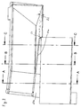
Fig. 1 eine perspektivische Ansicht einer erfindungsgemäßen Vorrichtung zum Vereinzeln von Stückgutteilen zeigt, wobei eine erste Fördereinrichtung in einem Übergabebereich und eine zweite Fördereinrichtung in einem Übernahmebereich dargestellt ist, -
Fig. 2 die Vorrichtung nachFig. 1 aus einer anderen Blickrichtung zeigt, -
Fig. 3 eine Draufsicht der Vorrichtung nachFig. 1 und2 zeigt, -
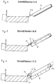
Fig. 4 eine Schnittansicht gemäßFig. 3 A-A zeigt, -
Fig. 5 eine Schnittansicht gemäßFig. 3 B-B zeigt, und -
Fig. 6 eine Schnittansicht gemäßFig. 3 C-C zeigt. - Die dargestellte Vorrichtung zum Vereinzeln von Stückgutteilen umfasst eine erste Fördereinrichtung 2 mit einem Förderband 4, das in einer Zuführrichtung 10 angetrieben ist. Eine erste Förderoberfläche 12 der ersten Fördereinrichtung 2 bzw. des Förderbands 4 ist quer zur Zuführrichtung 10 unter einem Querneigungswinkel 14 bezüglich einer Horizontalebene 20 geneigt angeordnet, damit in Zuführrichtung 10 zugeführte Stückgutteile quer zur Zuführrichtung 10 abgleiten können. Die Größe des Querneigungswinkels 14 hängt unter anderem von den Gleiteigenschaften der zugeführten Stückgutteile ab, da die Vorrichtung darauf beruht, dass übereinander liegende Stückgutteile voneinander abgleiten. Der Querneigungswinkel 14 kann beispielsweise in einem Bereich zwischen 5° und 45° liegen und beträgt bevorzugt zwischen 20° und 35°. Der Winkel 14 kann einstellbar oder auch während des Betriebs der Vorrichtung verstellbar oder an momentane Situationen anpassbar sein.
- Weiterhin ist die erste Förderfläche unter einem Längsneigungswinkel 15 in Zuführrichtung 10 gesehen ansteigend angeordnet, beispielsweise mit ca. 5 bis 10° Steigung.
- Die erste Fördereinrichtung 2 umfasst einen Zuführbereich 16, in dem die Stückgutteile im Wesentlichen in Zuführrichtung 10 gefördert werden, und einen in Zuführrichtung 10 an den Zuführbereich 16 anschließenden Übergabebereich 18 (schraffiert), in dem die Stückgutteile eine Bewegungskomponente quer zur Zuführrichtung 10 erhalten und von der ersten Fördereinrichtung 2 abgleiten. In dem Zuführbereich 16 kann die erste Förderoberfläche einen anderen Querneigungswinkel haben als in dem Übergabebereich, insbesondere einen kleineren Querneigungswinkel, bis hin zu 0° (ohne Querneigung).
- Obwohl die Förderoberfläche 12 der ersten Fördereinrichtung 2 zwischen angedeuteten Antriebs- und Umlenkrollen verlaufen kann, ist eine Variante möglich, die in
Fig. 1 und3 angedeutet ist. Ein Teil der Förderoberfläche 12, eine Förderoberfläche 58, schließt sich mittels eines sogenannten Knickstoßes in Zuführrichtung 10 an einen ersten Teil der Förderoberfläche 12 an und kann als getrenntes Förderband ausgebildet sein. Die Förderoberfläche 58 kann in Zuführrichtung 10 gesehen bezüglich einer Horizontalebene 20 abfallend unter einem Längsneigungswinkel 60 von 5° bis 20° geneigt sein, vorzugsweise unter 10°. - Benachbart zu der ersten Fördereinrichtung 2 ist eine zweite Fördereinrichtung 30 mit einem zweiten Förderband 32 angeordnet, das in einer Abförderrichtung 34 oder Längsrichtung angetrieben ist und eine zweite Förderoberfläche 36 aufweist. Die zweite Fördereinrichtung 30 weist benachbart zu dem Übergabebereich 18 der ersten Fördereinrichtung 2 einen Übernahmebereich 38 (schraffiert) auf, sowie einen sich in Abförderrichtung 34 an den Übernahmebereich 38 anschließenden Abförderbereich 40. Während von der ersten Fördereinrichtung 2 in dem Übernahmebereich 38 zugeführte Stückgutteile eine Bewegungskomponente quer zur Abförderrichtung 34 aufweisen, werden sie im Abförderbereich 40 im Wesentlichen in Abförderrichtung 34 bewegt. Die Abförderrichtung 34 kann parallel zu der Zuführrichtung 10 sein oder einen beliebigen Winkel damit bilden.
- Zwischen dem Übergabebereich 18 der ersten Fördereinrichtung 2 und dem Übernahmebereich 38 der zweiten Fördereinrichtung 30 ist erfindungsgemäß eine Leiteinrichtung 50 angeordnet, die als feststehendes Element mit einer zu der ersten Fördereinrichtung 2 weisenden Leitfläche 52 ausgebildet ist. Wie insbesondere aus den Schnittansichten gemäß
Fig. 4, 5 und 6 hervorgeht, ist die Leitfläche 52 beispielhaft senkrecht zu der ersten Förderoberfläche 12 oder deren Erstreckungsebene 12a angeordnet und weist diesbezüglich eine Höhe H auf, die sich entlang des Übergabebereichs 18 in Zuführrichtung 10 gesehen kontinuierlich bis auf Null verringert. WieFig. 1 und2 zeigen, verläuft die Leiteinrichtung 50 in dem dargestellten Beispiel in einem ersten Teilstück 50a wie vorstehend beschrieben, während ein zweites, anschließendes Teilstück 50b der Leiteinrichtung 50 als ebene Übergangsfläche zwischen der ersten Fördereinrichtung 2 und der zweiten Fördereinrichtung 30 ausgebildet ist. Während das zweite Teilstück oder die Übergangsfläche 50b in der dargestellten Ausführung in einer Ebene mit der ersten Förderoberfläche 12 ausgebildet ist, kann in einer Variante vorgesehen sein, dass die Übergangsfläche 50b in Bezug auf die erste Förderoberfläche 12 abgesenkt oder vertieft ausgebildet ist. Die Förderoberfläche 58 kann benachbart zu der Übergangsfläche 50b angeordnet sein. - Die Leitfläche 52 könnte parallel zur Zuführrichtung 10 verlaufen, ist jedoch bevorzugt unter einem Stauwinkel 22 (
Fig. 3 ) von beispielsweise 5° dazu angeordnet, um eine Stauwirkung der gegen die Leiteinrichtung geförderten Stückgutteile zu erreichen. - Die Leitfläche 52 geht in eine zur zweiten Fördereinrichtung geneigte Abgabefläche 54 über, die schräg geneigt zur zweiten Förderoberfläche 36 verläuft. Die Abgabefläche 54 schließt an die Übergangsfläche 50b an.
- Wie bereits in der Beschreibungseinleitung ausgeführt ist, handelt es sich bei der ersten Fördereinrichtung 2 um einen Gurtförderer, oder aber bevorzugt um ein als Ganzes in Zuführrichtung bewegtes Förder- oder Modulband mit eingebetteten Rollen. Die eingebetteten Rollen sind bevorzugt nicht angetrieben und weisen eine in Zuführrichtung 10 ausgerichtete Drehachse auf, so dass Stückgutteile in Zuführrichtung 10 gefördert werden können, aber unmittelbar auf der ersten Fördereinrichtung aufliegende Stückgutteile mit sehr geringen (Roll-)Reibwerten quer zur Zuführrichtung in Richtung auf die Leiteinrichtung und die zweite Fördereinrichtung abgleiten können. Die Rollen sind beispielsweise mit Gummi beschichtet und haben einen hohen Reibwert, in Zuführrichtung 10 gesehen.
- Die zweite Fördereinrichtung 30 ist bevorzugt als Schrägrollenförderer, beispielsweise in Fischgrätanordnung, ausgebildet, wobei die Rollen unter einem spitzen Winkel zur Förderrichtung angeordnet sind, beispielsweise unter einem Winkel zwischen 10° und 20°. Alternativ besteht die Möglichkeit, die zweite Fördereinrichtung 30 mit selektiv aktivierbaren bzw. antreibbaren Rollen gemäß
WO2006/121750 A1 auszuführen. Diese Gestaltung der zweiten Fördereinrichtung 30 dient dazu, Stückgutteile, die über die Leiteinrichtung auf den Übernahmebereich 38 gelangt sind, schnell aus diesem Bereich herauszufördern, um einen Stau von Stückgutteilen im Übernahmebereich 38 zu verhindern, und um insbesondere zu verhindern, dass sich Stückgutteile übereinander legen. -
- 2
- erste Fördereinrichtung
- 4
- erstes Förderband
- 6, 8
- Antriebs- und Umlenkrolle
- 10
- Zuführrichtung
- 12
- erste Förderoberfläche
- 12a
- Erstreckungsebene (von 12)
- 14
- Querneigungswinkel (von 12)
- 15
- Längsneigungswinkel (von 12)
- 16
- Zuführbereich
- 18
- Übergabebereich
- 20
- Horizontalebene
- 22
- Stauwinkel
- 30
- zweite Fördereinrichtung
- 32
- zweites Förderband
- 34
- Abförderrichtung (Längsrichtung)
- 36
- zweite Förderoberfläche
- 38
- Übernahmebereich
- 40
- Abförderbereich
- 50
- Leiteinrichtung
- 50a
- erstes Teilstück
- 50b
- zweites Teilstück (Übergangsfläche)
- 52
- Leitfläche
- 58
- Förderoberfläche
- 60
- Längsneigungswinkel (von 58)
- H
- Höhe (von 52 bezüglich 12)
Claims (13)
- Vorrichtung zum Vereinzeln von Stückgutteilen, mit einer ersten, in einer Zuführrichtung (10) arbeitenden Fördereinrichtung (2) mit einer ersten Förderoberfläche (12) zum Zuführen von Stückgutteilen, mit einer benachbart zu einem Übergabebereich (18) der ersten Fördereinrichtung (2) angeordneten zweiten Fördereinrichtung (30) mit einer zweiten Förderoberfläche (36) zum Übernehmen der mit der ersten Fördereinrichtung (2) zugeführten Stückgutteile in einem Übernahmebereich (38) und zum Abfördern der Stückgutteile aus dem Übernahmebereich (38), wobei die erste Förderoberfläche (12) in dem Übergabebereich (18) quer zu der Zuführrichtung (10) und in Richtung der zweiten Fördereinrichtung (30) bezüglich einer Horizontalebene (20) unter einem Querneigungswinkel (14) abfallend geneigt ist, mit einer zwischen dem Übergabebereich (18) der ersten Fördereinrichtung (2) und dem Übernahmebereich (38) der zweiten Fördereinrichtung (30) angeordneten Leiteinrichtung (50) zum kontrollierten Überleiten von Stückgutteilen von der ersten zu der zweiten Fördereinrichtung, dadurch gekennzeichnet, dass die Leiteinrichtung (50) eine entlang des Übergabebereichs (18) verlaufende Leitfläche (52) aufweist, die mit einer in Zuführrichtung (10) abnehmenden Höhe (H) über eine Erstreckungsebene (12a) der ersten Förderoberfläche (12) vorsteht.
- Vorrichtung nach Anspruch 1, dadurch gekennzeichnet, dass die erste Förderoberfläche (12) in Zuführrichtung (10) gesehen horizontal oder unter einem Längsneigungswinkel (15) bezüglich der Horizontalebene (20) ansteigend geneigt angeordnet ist.
- Vorrichtung nach Anspruch 1 oder 2, dadurch gekennzeichnet, dass die zweite Förderoberfläche (36) quer zu einer Längsrichtung (34) gesehen horizontal angeordnet ist.
- Vorrichtung nach einem der vorangehenden Ansprüche, dadurch gekennzeichnet, dass die zweite Förderoberfläche (36) in einer Längsrichtung (34) gesehen horizontal, ansteigend oder abfallend geneigt angeordnet ist.
- Vorrichtung nach einem der vorangehenden Ansprüche, dadurch gekennzeichnet, dass die Leitfläche (52) mit der ersten Förderoberfläche (12) einen Winkel zwischen 90° und 120° bildet.
- Vorrichtung nach einem der vorangehenden Ansprüche, dadurch gekennzeichnet, dass die Leitfläche (52) eben ist.
- Vorrichtung nach einem der Ansprüche 1 bis 5, dadurch gekennzeichnet, dass die Leitfläche reibungsarm beschichtet oder mit eingebetteten Rollen versehen ist, deren Drehachsen parallel zur Zuführeinrichtung (10) sein können.
- Vorrichtung nach einem der vorangehenden Ansprüche, dadurch gekennzeichnet, dass sich ein an die Leiteinrichtung (50) angrenzender Teil des Übergabebereichs (18) der ersten Förderoberfläche (12) oberhalb der zweiten Förderoberfläche (36) befindet.
- Vorrichtung nach einem der Ansprüche 1 bis 7 , dadurch gekennzeichnet, dass ein an die Übergabefläche (54) angrenzender Teil des Übernahmebereichs (38) der zweiten Förderoberfläche (36) in gleicher Höhe mit der Übergabefläche (18) verläuft.
- Vorrichtung nach einem der vorangehenden Ansprüche, dadurch gekennzeichnet, dass die erste Fördereinrichtung (2) ein Gurt- oder Rollenförderer ist, insbesondere in Form eines Förder- oder Modulbands mit eingebetteten Rollen.
- Vorrichtung nach Anspruch 10, dadurch gekennzeichnet, dass die eingebetteten Rollen als nicht angetriebene Rollen mit einer Drehachse in Zuführrichtung (10) ausgebildet sind.
- Vorrichtung nach einem der vorangehenden Ansprüche, dadurch gekennzeichnet, dass die zweite Fördereinrichtung (30) ein Gurt- oder Rollenförderer ist, der ein Förder- oder Modulband mit eingebetteten Rollen aufweisen kann.
- Vorrichtung nach Anspruch 12, dadurch gekennzeichnet, dass die eingebetteten Rollen selektiv aktivierbar sind.
Applications Claiming Priority (1)
| Application Number | Priority Date | Filing Date | Title |
|---|---|---|---|
| DE202013005786U DE202013005786U1 (de) | 2013-06-27 | 2013-06-27 | Vorrichtung zum Vereinzeln von Stückgutteilen |
Publications (2)
| Publication Number | Publication Date |
|---|---|
| EP2818436A1 EP2818436A1 (de) | 2014-12-31 |
| EP2818436B1 true EP2818436B1 (de) | 2016-03-02 |
Family
ID=48951214
Family Applications (1)
| Application Number | Title | Priority Date | Filing Date |
|---|---|---|---|
| EP14002173.4A Not-in-force EP2818436B1 (de) | 2013-06-27 | 2014-06-25 | Vorrichtung zum Vereinzeln von Stückgutteilen |
Country Status (4)
| Country | Link |
|---|---|
| US (1) | US9169084B2 (de) |
| EP (1) | EP2818436B1 (de) |
| CN (1) | CN104249921B (de) |
| DE (1) | DE202013005786U1 (de) |
Families Citing this family (6)
| Publication number | Priority date | Publication date | Assignee | Title |
|---|---|---|---|---|
| DE202015103937U1 (de) * | 2015-07-09 | 2015-09-03 | Alfons Brass Logisitk Gmbh & Co. Kg | Depalettiervorrichtung für Reifen |
| CN108946093B (zh) * | 2017-05-25 | 2021-04-30 | Ykk株式会社 | 搬送装置及搬送方法 |
| CN110406939B (zh) * | 2019-08-19 | 2024-05-28 | 成都信息工程大学 | 车载摄像头分拣输出装置 |
| JP7327337B2 (ja) * | 2020-10-02 | 2023-08-16 | 株式会社ダイフク | 物品搬送装置 |
| CN114890108A (zh) * | 2022-04-13 | 2022-08-12 | 江苏富联通讯技术有限公司 | 一种用于5g模块加工的自动输送装置及其使用方法 |
| CN118477831B (zh) * | 2024-07-09 | 2024-09-13 | 常州科顺检测技术服务有限公司 | 一种应用于动力锂电池组bms测试系统的转动式调节装置 |
Family Cites Families (12)
| Publication number | Priority date | Publication date | Assignee | Title |
|---|---|---|---|---|
| US2956665A (en) * | 1958-01-23 | 1960-10-18 | John D Macarthur | Part feeding and orienting device |
| US3913730A (en) * | 1974-03-08 | 1975-10-21 | Fairchild Industries | Article transferring apparatus |
| US6015039A (en) * | 1997-02-04 | 2000-01-18 | United Parcel Service Of America, Inc. | High speed tilted belt sorter |
| US6491154B2 (en) | 2000-12-26 | 2002-12-10 | Sandvik Sorting Systems, Inc. | Unstacker for unstacking items conveyed in a bulk stream |
| US7344018B2 (en) | 2005-05-06 | 2008-03-18 | Laitram, L.L.C. | Conveyor and method for diverting closely spaced articles |
| DE502006005659D1 (de) | 2006-05-12 | 2010-01-28 | Liechtenstein Alexander Von | Vorrichtung zum Vereinzeln im Wesentlichen quaderförmiger Stückgüter |
| DE102008035690A1 (de) * | 2008-07-30 | 2010-03-04 | Siemens Aktiengesellschaft | Kippschalen-Sortierförderer |
| AU2011224626A1 (en) | 2010-03-08 | 2012-08-23 | Laitram, L.L.C. | Package-culling conveyor system and method |
| DE102010025744A1 (de) * | 2010-06-30 | 2012-01-05 | Krones Aktiengesellschaft | Ausleitvorrichtung |
| JP4809496B1 (ja) * | 2010-12-24 | 2011-11-09 | 株式会社ダイシン | 搬送物分離機構及びこれを備えた搬送装置 |
| JP5316907B2 (ja) * | 2011-03-17 | 2013-10-16 | 株式会社ダイフク | 物品搬送設備 |
| DE202012100777U1 (de) * | 2012-03-05 | 2013-06-12 | Caterpillar Global Mining Europe Gmbh | Plattenbandförderer für Gewinnungsanlagen und Transportplatten hierfür |
-
2013
- 2013-06-27 DE DE202013005786U patent/DE202013005786U1/de not_active Expired - Lifetime
-
2014
- 2014-06-25 EP EP14002173.4A patent/EP2818436B1/de not_active Not-in-force
- 2014-06-27 CN CN201410295793.4A patent/CN104249921B/zh not_active Expired - Fee Related
- 2014-06-27 US US14/316,909 patent/US9169084B2/en not_active Expired - Fee Related
Also Published As
| Publication number | Publication date |
|---|---|
| CN104249921B (zh) | 2016-09-14 |
| EP2818436A1 (de) | 2014-12-31 |
| US9169084B2 (en) | 2015-10-27 |
| DE202013005786U1 (de) | 2013-07-10 |
| US20150001042A1 (en) | 2015-01-01 |
| CN104249921A (zh) | 2014-12-31 |
Similar Documents
| Publication | Publication Date | Title |
|---|---|---|
| EP2818436B1 (de) | Vorrichtung zum Vereinzeln von Stückgutteilen | |
| EP3115322B1 (de) | Verfahren und vorrichtung zum depalettieren von reifen | |
| EP2986543B1 (de) | Paketvereinzelung | |
| EP2243728A2 (de) | Förderer zum Transportieren von Gegenständen | |
| DE102010049281B4 (de) | Schwerkraftrutsche | |
| EP3248913B1 (de) | Singulationsförderer und verfahren zum fördern und vereinzeln von stückgut entlang wenigstens einer transportbahn | |
| DE202012013047U1 (de) | Vorrichtung zum Sammeln von Produkten sowie Anlage mit einer solchen Vorrichtung | |
| EP3381842B1 (de) | Fördervorrichtung zum zusammenführen von stückgutteilen von mehreren einschleusförderern | |
| EP3684714B1 (de) | Aufgabeeinrichtung zur aufgabe von produkten auf ein förderband | |
| EP2531425A1 (de) | Verfahren und vorrichtung zum selektiven kippen von gegenständen | |
| EP1559663B1 (de) | Verfahren und Fördervorrichtung zur Förderung von mit einem Kragen versehenen Gegenständen | |
| DE102017006855B4 (de) | Kastenrutsche für eine Endstellenvorrichtung | |
| WO2022122792A2 (de) | Ausschleusvorrichtung | |
| DE2015512A1 (de) | Umsetzvorrichtung für Behälter zwischen einem ersten und einem zweiten Förderer | |
| DE10317417B4 (de) | Vereinzelungs- und Fördervorrichtung | |
| EP3498639B1 (de) | Vorrichtung zum zusammenführen von zwei in unterschiedlichen höhen angeordneten stückgutströmen | |
| WO2022129342A1 (de) | Behälterzuführvorrichtung und verfahren zum betreiben der behälterzuführvorrichtung | |
| EP2609023A1 (de) | Verfahren und vorrichtung zum kontrollierten übergeben eines stückguts von einem zuführförderer auf einen förderer | |
| EP3263493A1 (de) | Durchlaufregal zum kommissionieren von lagereinheiten | |
| DE102010028500A1 (de) | Einrichtung zur aufrechten Förderung eines Behältnisses, vorzugsweise eines Preforms | |
| EP2754626A1 (de) | Fördervorrichtung mit konkavem Gurt | |
| EP3078270B1 (de) | Vorrichtung zum kontinuierlichen gefalteten ablegen von teig auf einem fördermittel | |
| DE102004054490A1 (de) | Vorrichtung zum Ändern der Orientierung von Blattstapeln | |
| EP1538115B1 (de) | Verfahren zum Transportieren von Produkten | |
| EP3740445A1 (de) | Übergabe von stückgütern |
Legal Events
| Date | Code | Title | Description |
|---|---|---|---|
| PUAI | Public reference made under article 153(3) epc to a published international application that has entered the european phase |
Free format text: ORIGINAL CODE: 0009012 |
|
| 17P | Request for examination filed |
Effective date: 20140625 |
|
| AK | Designated contracting states |
Kind code of ref document: A1 Designated state(s): AL AT BE BG CH CY CZ DE DK EE ES FI FR GB GR HR HU IE IS IT LI LT LU LV MC MK MT NL NO PL PT RO RS SE SI SK SM TR |
|
| AX | Request for extension of the european patent |
Extension state: BA ME |
|
| R17P | Request for examination filed (corrected) |
Effective date: 20141218 |
|
| RBV | Designated contracting states (corrected) |
Designated state(s): AL AT BE BG CH CY CZ DE DK EE ES FI FR GB GR HR HU IE IS IT LI LT LU LV MC MK MT NL NO PL PT RO RS SE SI SK SM TR |
|
| GRAP | Despatch of communication of intention to grant a patent |
Free format text: ORIGINAL CODE: EPIDOSNIGR1 |
|
| INTG | Intention to grant announced |
Effective date: 20151002 |
|
| RIC1 | Information provided on ipc code assigned before grant |
Ipc: B65G 47/30 20060101ALI20150923BHEP Ipc: B65G 47/14 20060101AFI20150923BHEP Ipc: B65G 47/57 20060101ALI20150923BHEP Ipc: B65G 47/31 20060101ALN20150923BHEP |
|
| GRAS | Grant fee paid |
Free format text: ORIGINAL CODE: EPIDOSNIGR3 |
|
| GRAA | (expected) grant |
Free format text: ORIGINAL CODE: 0009210 |
|
| AK | Designated contracting states |
Kind code of ref document: B1 Designated state(s): AL AT BE BG CH CY CZ DE DK EE ES FI FR GB GR HR HU IE IS IT LI LT LU LV MC MK MT NL NO PL PT RO RS SE SI SK SM TR |
|
| REG | Reference to a national code |
Ref country code: GB Ref legal event code: FG4D Free format text: NOT ENGLISH |
|
| REG | Reference to a national code |
Ref country code: AT Ref legal event code: REF Ref document number: 777860 Country of ref document: AT Kind code of ref document: T Effective date: 20160315 Ref country code: CH Ref legal event code: EP |
|
| REG | Reference to a national code |
Ref country code: IE Ref legal event code: FG4D Free format text: LANGUAGE OF EP DOCUMENT: GERMAN |
|
| REG | Reference to a national code |
Ref country code: DE Ref legal event code: R096 Ref document number: 502014000399 Country of ref document: DE |
|
| REG | Reference to a national code |
Ref country code: FR Ref legal event code: PLFP Year of fee payment: 3 |
|
| REG | Reference to a national code |
Ref country code: NL Ref legal event code: FP |
|
| REG | Reference to a national code |
Ref country code: LT Ref legal event code: MG4D |
|
| PG25 | Lapsed in a contracting state [announced via postgrant information from national office to epo] |
Ref country code: ES Free format text: LAPSE BECAUSE OF FAILURE TO SUBMIT A TRANSLATION OF THE DESCRIPTION OR TO PAY THE FEE WITHIN THE PRESCRIBED TIME-LIMIT Effective date: 20160302 Ref country code: FI Free format text: LAPSE BECAUSE OF FAILURE TO SUBMIT A TRANSLATION OF THE DESCRIPTION OR TO PAY THE FEE WITHIN THE PRESCRIBED TIME-LIMIT Effective date: 20160302 Ref country code: NO Free format text: LAPSE BECAUSE OF FAILURE TO SUBMIT A TRANSLATION OF THE DESCRIPTION OR TO PAY THE FEE WITHIN THE PRESCRIBED TIME-LIMIT Effective date: 20160602 Ref country code: HR Free format text: LAPSE BECAUSE OF FAILURE TO SUBMIT A TRANSLATION OF THE DESCRIPTION OR TO PAY THE FEE WITHIN THE PRESCRIBED TIME-LIMIT Effective date: 20160302 Ref country code: GR Free format text: LAPSE BECAUSE OF FAILURE TO SUBMIT A TRANSLATION OF THE DESCRIPTION OR TO PAY THE FEE WITHIN THE PRESCRIBED TIME-LIMIT Effective date: 20160603 |
|
| PG25 | Lapsed in a contracting state [announced via postgrant information from national office to epo] |
Ref country code: PL Free format text: LAPSE BECAUSE OF FAILURE TO SUBMIT A TRANSLATION OF THE DESCRIPTION OR TO PAY THE FEE WITHIN THE PRESCRIBED TIME-LIMIT Effective date: 20160302 Ref country code: LV Free format text: LAPSE BECAUSE OF FAILURE TO SUBMIT A TRANSLATION OF THE DESCRIPTION OR TO PAY THE FEE WITHIN THE PRESCRIBED TIME-LIMIT Effective date: 20160302 Ref country code: LT Free format text: LAPSE BECAUSE OF FAILURE TO SUBMIT A TRANSLATION OF THE DESCRIPTION OR TO PAY THE FEE WITHIN THE PRESCRIBED TIME-LIMIT Effective date: 20160302 Ref country code: SE Free format text: LAPSE BECAUSE OF FAILURE TO SUBMIT A TRANSLATION OF THE DESCRIPTION OR TO PAY THE FEE WITHIN THE PRESCRIBED TIME-LIMIT Effective date: 20160302 Ref country code: RS Free format text: LAPSE BECAUSE OF FAILURE TO SUBMIT A TRANSLATION OF THE DESCRIPTION OR TO PAY THE FEE WITHIN THE PRESCRIBED TIME-LIMIT Effective date: 20160302 |
|
| PG25 | Lapsed in a contracting state [announced via postgrant information from national office to epo] |
Ref country code: IS Free format text: LAPSE BECAUSE OF FAILURE TO SUBMIT A TRANSLATION OF THE DESCRIPTION OR TO PAY THE FEE WITHIN THE PRESCRIBED TIME-LIMIT Effective date: 20160702 Ref country code: EE Free format text: LAPSE BECAUSE OF FAILURE TO SUBMIT A TRANSLATION OF THE DESCRIPTION OR TO PAY THE FEE WITHIN THE PRESCRIBED TIME-LIMIT Effective date: 20160302 |
|
| PG25 | Lapsed in a contracting state [announced via postgrant information from national office to epo] |
Ref country code: RO Free format text: LAPSE BECAUSE OF FAILURE TO SUBMIT A TRANSLATION OF THE DESCRIPTION OR TO PAY THE FEE WITHIN THE PRESCRIBED TIME-LIMIT Effective date: 20160302 Ref country code: SM Free format text: LAPSE BECAUSE OF FAILURE TO SUBMIT A TRANSLATION OF THE DESCRIPTION OR TO PAY THE FEE WITHIN THE PRESCRIBED TIME-LIMIT Effective date: 20160302 Ref country code: CZ Free format text: LAPSE BECAUSE OF FAILURE TO SUBMIT A TRANSLATION OF THE DESCRIPTION OR TO PAY THE FEE WITHIN THE PRESCRIBED TIME-LIMIT Effective date: 20160302 Ref country code: SK Free format text: LAPSE BECAUSE OF FAILURE TO SUBMIT A TRANSLATION OF THE DESCRIPTION OR TO PAY THE FEE WITHIN THE PRESCRIBED TIME-LIMIT Effective date: 20160302 Ref country code: PT Free format text: LAPSE BECAUSE OF FAILURE TO SUBMIT A TRANSLATION OF THE DESCRIPTION OR TO PAY THE FEE WITHIN THE PRESCRIBED TIME-LIMIT Effective date: 20160704 |
|
| REG | Reference to a national code |
Ref country code: DE Ref legal event code: R097 Ref document number: 502014000399 Country of ref document: DE |
|
| PG25 | Lapsed in a contracting state [announced via postgrant information from national office to epo] |
Ref country code: BE Free format text: LAPSE BECAUSE OF NON-PAYMENT OF DUE FEES Effective date: 20160630 |
|
| PLBE | No opposition filed within time limit |
Free format text: ORIGINAL CODE: 0009261 |
|
| STAA | Information on the status of an ep patent application or granted ep patent |
Free format text: STATUS: NO OPPOSITION FILED WITHIN TIME LIMIT |
|
| PG25 | Lapsed in a contracting state [announced via postgrant information from national office to epo] |
Ref country code: DK Free format text: LAPSE BECAUSE OF FAILURE TO SUBMIT A TRANSLATION OF THE DESCRIPTION OR TO PAY THE FEE WITHIN THE PRESCRIBED TIME-LIMIT Effective date: 20160302 Ref country code: MC Free format text: LAPSE BECAUSE OF FAILURE TO SUBMIT A TRANSLATION OF THE DESCRIPTION OR TO PAY THE FEE WITHIN THE PRESCRIBED TIME-LIMIT Effective date: 20160302 |
|
| 26N | No opposition filed |
Effective date: 20161205 |
|
| PG25 | Lapsed in a contracting state [announced via postgrant information from national office to epo] |
Ref country code: SI Free format text: LAPSE BECAUSE OF FAILURE TO SUBMIT A TRANSLATION OF THE DESCRIPTION OR TO PAY THE FEE WITHIN THE PRESCRIBED TIME-LIMIT Effective date: 20160302 Ref country code: BG Free format text: LAPSE BECAUSE OF FAILURE TO SUBMIT A TRANSLATION OF THE DESCRIPTION OR TO PAY THE FEE WITHIN THE PRESCRIBED TIME-LIMIT Effective date: 20160602 |
|
| REG | Reference to a national code |
Ref country code: IE Ref legal event code: MM4A |
|
| PG25 | Lapsed in a contracting state [announced via postgrant information from national office to epo] |
Ref country code: IE Free format text: LAPSE BECAUSE OF NON-PAYMENT OF DUE FEES Effective date: 20160625 |
|
| REG | Reference to a national code |
Ref country code: FR Ref legal event code: PLFP Year of fee payment: 4 |
|
| REG | Reference to a national code |
Ref country code: CH Ref legal event code: PL |
|
| PG25 | Lapsed in a contracting state [announced via postgrant information from national office to epo] |
Ref country code: LI Free format text: LAPSE BECAUSE OF NON-PAYMENT OF DUE FEES Effective date: 20170630 Ref country code: CH Free format text: LAPSE BECAUSE OF NON-PAYMENT OF DUE FEES Effective date: 20170630 |
|
| PG25 | Lapsed in a contracting state [announced via postgrant information from national office to epo] |
Ref country code: HU Free format text: LAPSE BECAUSE OF FAILURE TO SUBMIT A TRANSLATION OF THE DESCRIPTION OR TO PAY THE FEE WITHIN THE PRESCRIBED TIME-LIMIT; INVALID AB INITIO Effective date: 20140625 |
|
| REG | Reference to a national code |
Ref country code: FR Ref legal event code: PLFP Year of fee payment: 5 |
|
| PG25 | Lapsed in a contracting state [announced via postgrant information from national office to epo] |
Ref country code: MT Free format text: LAPSE BECAUSE OF FAILURE TO SUBMIT A TRANSLATION OF THE DESCRIPTION OR TO PAY THE FEE WITHIN THE PRESCRIBED TIME-LIMIT Effective date: 20160302 Ref country code: LU Free format text: LAPSE BECAUSE OF NON-PAYMENT OF DUE FEES Effective date: 20160625 Ref country code: CY Free format text: LAPSE BECAUSE OF FAILURE TO SUBMIT A TRANSLATION OF THE DESCRIPTION OR TO PAY THE FEE WITHIN THE PRESCRIBED TIME-LIMIT Effective date: 20160302 Ref country code: MK Free format text: LAPSE BECAUSE OF FAILURE TO SUBMIT A TRANSLATION OF THE DESCRIPTION OR TO PAY THE FEE WITHIN THE PRESCRIBED TIME-LIMIT Effective date: 20160302 |
|
| PG25 | Lapsed in a contracting state [announced via postgrant information from national office to epo] |
Ref country code: AL Free format text: LAPSE BECAUSE OF FAILURE TO SUBMIT A TRANSLATION OF THE DESCRIPTION OR TO PAY THE FEE WITHIN THE PRESCRIBED TIME-LIMIT Effective date: 20160302 Ref country code: TR Free format text: LAPSE BECAUSE OF FAILURE TO SUBMIT A TRANSLATION OF THE DESCRIPTION OR TO PAY THE FEE WITHIN THE PRESCRIBED TIME-LIMIT Effective date: 20160302 |
|
| REG | Reference to a national code |
Ref country code: DE Ref legal event code: R082 Ref document number: 502014000399 Country of ref document: DE Representative=s name: BOEHMERT & BOEHMERT ANWALTSPARTNERSCHAFT MBB -, DE Ref country code: DE Ref legal event code: R081 Ref document number: 502014000399 Country of ref document: DE Owner name: BEUMER GROUP GMBH & CO. KG, DE Free format text: FORMER OWNER: BEUMER GMBH & CO. KG, 59269 BECKUM, DE |
|
| REG | Reference to a national code |
Ref country code: NL Ref legal event code: HC Owner name: BEUMER GROUP GMBH & CO. KG; DE Free format text: DETAILS ASSIGNMENT: CHANGE OF OWNER(S), CHANGE OF OWNER(S) NAME; FORMER OWNER NAME: BEUMER GMBH & CO. KG Effective date: 20191115 |
|
| REG | Reference to a national code |
Ref country code: AT Ref legal event code: HC Ref document number: 777860 Country of ref document: AT Kind code of ref document: T Owner name: BEUMER GROUP GMBH & CO. KG, DE Effective date: 20200624 |
|
| PGFP | Annual fee paid to national office [announced via postgrant information from national office to epo] |
Ref country code: NL Payment date: 20220621 Year of fee payment: 9 Ref country code: GB Payment date: 20220623 Year of fee payment: 9 Ref country code: DE Payment date: 20220621 Year of fee payment: 9 |
|
| PGFP | Annual fee paid to national office [announced via postgrant information from national office to epo] |
Ref country code: AT Payment date: 20220617 Year of fee payment: 9 |
|
| PGFP | Annual fee paid to national office [announced via postgrant information from national office to epo] |
Ref country code: FR Payment date: 20220621 Year of fee payment: 9 |
|
| PGFP | Annual fee paid to national office [announced via postgrant information from national office to epo] |
Ref country code: IT Payment date: 20220630 Year of fee payment: 9 |
|
| P01 | Opt-out of the competence of the unified patent court (upc) registered |
Effective date: 20230411 |
|
| REG | Reference to a national code |
Ref country code: DE Ref legal event code: R119 Ref document number: 502014000399 Country of ref document: DE |
|
| REG | Reference to a national code |
Ref country code: NL Ref legal event code: MM Effective date: 20230701 |
|
| REG | Reference to a national code |
Ref country code: AT Ref legal event code: MM01 Ref document number: 777860 Country of ref document: AT Kind code of ref document: T Effective date: 20230625 |
|
| GBPC | Gb: european patent ceased through non-payment of renewal fee |
Effective date: 20230625 |
|
| PG25 | Lapsed in a contracting state [announced via postgrant information from national office to epo] |
Ref country code: NL Free format text: LAPSE BECAUSE OF NON-PAYMENT OF DUE FEES Effective date: 20230701 |
|
| PG25 | Lapsed in a contracting state [announced via postgrant information from national office to epo] |
Ref country code: AT Free format text: LAPSE BECAUSE OF NON-PAYMENT OF DUE FEES Effective date: 20230625 |
|
| PG25 | Lapsed in a contracting state [announced via postgrant information from national office to epo] |
Ref country code: DE Free format text: LAPSE BECAUSE OF NON-PAYMENT OF DUE FEES Effective date: 20240103 Ref country code: AT Free format text: LAPSE BECAUSE OF NON-PAYMENT OF DUE FEES Effective date: 20230625 Ref country code: GB Free format text: LAPSE BECAUSE OF NON-PAYMENT OF DUE FEES Effective date: 20230625 |
|
| PG25 | Lapsed in a contracting state [announced via postgrant information from national office to epo] |
Ref country code: FR Free format text: LAPSE BECAUSE OF NON-PAYMENT OF DUE FEES Effective date: 20230630 |
|
| PG25 | Lapsed in a contracting state [announced via postgrant information from national office to epo] |
Ref country code: IT Free format text: LAPSE BECAUSE OF NON-PAYMENT OF DUE FEES Effective date: 20230625 |