EP3498523B1 - System und verfahren für vorladetests zur verhinderung des missbrauchs einer ladestation für elektrofahrzeuge - Google Patents
System und verfahren für vorladetests zur verhinderung des missbrauchs einer ladestation für elektrofahrzeuge Download PDFInfo
- Publication number
- EP3498523B1 EP3498523B1 EP18208752.8A EP18208752A EP3498523B1 EP 3498523 B1 EP3498523 B1 EP 3498523B1 EP 18208752 A EP18208752 A EP 18208752A EP 3498523 B1 EP3498523 B1 EP 3498523B1
- Authority
- EP
- European Patent Office
- Prior art keywords
- charging
- pilot signal
- state
- vehicle
- voltage level
- Prior art date
- Legal status (The legal status is an assumption and is not a legal conclusion. Google has not performed a legal analysis and makes no representation as to the accuracy of the status listed.)
- Active
Links
Images


Classifications
-
- B—PERFORMING OPERATIONS; TRANSPORTING
- B60—VEHICLES IN GENERAL
- B60L—PROPULSION OF ELECTRICALLY-PROPELLED VEHICLES; SUPPLYING ELECTRIC POWER FOR AUXILIARY EQUIPMENT OF ELECTRICALLY-PROPELLED VEHICLES; ELECTRODYNAMIC BRAKE SYSTEMS FOR VEHICLES IN GENERAL; MAGNETIC SUSPENSION OR LEVITATION FOR VEHICLES; MONITORING OPERATING VARIABLES OF ELECTRICALLY-PROPELLED VEHICLES; ELECTRIC SAFETY DEVICES FOR ELECTRICALLY-PROPELLED VEHICLES
- B60L53/00—Methods of charging batteries, specially adapted for electric vehicles; Charging stations or on-board charging equipment therefor; Exchange of energy storage elements in electric vehicles
- B60L53/10—Methods of charging batteries, specially adapted for electric vehicles; Charging stations or on-board charging equipment therefor; Exchange of energy storage elements in electric vehicles characterised by the energy transfer between the charging station and the vehicle
- B60L53/14—Conductive energy transfer
-
- B—PERFORMING OPERATIONS; TRANSPORTING
- B60—VEHICLES IN GENERAL
- B60L—PROPULSION OF ELECTRICALLY-PROPELLED VEHICLES; SUPPLYING ELECTRIC POWER FOR AUXILIARY EQUIPMENT OF ELECTRICALLY-PROPELLED VEHICLES; ELECTRODYNAMIC BRAKE SYSTEMS FOR VEHICLES IN GENERAL; MAGNETIC SUSPENSION OR LEVITATION FOR VEHICLES; MONITORING OPERATING VARIABLES OF ELECTRICALLY-PROPELLED VEHICLES; ELECTRIC SAFETY DEVICES FOR ELECTRICALLY-PROPELLED VEHICLES
- B60L53/00—Methods of charging batteries, specially adapted for electric vehicles; Charging stations or on-board charging equipment therefor; Exchange of energy storage elements in electric vehicles
- B60L53/10—Methods of charging batteries, specially adapted for electric vehicles; Charging stations or on-board charging equipment therefor; Exchange of energy storage elements in electric vehicles characterised by the energy transfer between the charging station and the vehicle
- B60L53/14—Conductive energy transfer
- B60L53/16—Connectors, e.g. plugs or sockets, specially adapted for charging electric vehicles
-
- B—PERFORMING OPERATIONS; TRANSPORTING
- B60—VEHICLES IN GENERAL
- B60L—PROPULSION OF ELECTRICALLY-PROPELLED VEHICLES; SUPPLYING ELECTRIC POWER FOR AUXILIARY EQUIPMENT OF ELECTRICALLY-PROPELLED VEHICLES; ELECTRODYNAMIC BRAKE SYSTEMS FOR VEHICLES IN GENERAL; MAGNETIC SUSPENSION OR LEVITATION FOR VEHICLES; MONITORING OPERATING VARIABLES OF ELECTRICALLY-PROPELLED VEHICLES; ELECTRIC SAFETY DEVICES FOR ELECTRICALLY-PROPELLED VEHICLES
- B60L53/00—Methods of charging batteries, specially adapted for electric vehicles; Charging stations or on-board charging equipment therefor; Exchange of energy storage elements in electric vehicles
- B60L53/30—Constructional details of charging stations
- B60L53/31—Charging columns specially adapted for electric vehicles
-
- B—PERFORMING OPERATIONS; TRANSPORTING
- B60—VEHICLES IN GENERAL
- B60L—PROPULSION OF ELECTRICALLY-PROPELLED VEHICLES; SUPPLYING ELECTRIC POWER FOR AUXILIARY EQUIPMENT OF ELECTRICALLY-PROPELLED VEHICLES; ELECTRODYNAMIC BRAKE SYSTEMS FOR VEHICLES IN GENERAL; MAGNETIC SUSPENSION OR LEVITATION FOR VEHICLES; MONITORING OPERATING VARIABLES OF ELECTRICALLY-PROPELLED VEHICLES; ELECTRIC SAFETY DEVICES FOR ELECTRICALLY-PROPELLED VEHICLES
- B60L53/00—Methods of charging batteries, specially adapted for electric vehicles; Charging stations or on-board charging equipment therefor; Exchange of energy storage elements in electric vehicles
- B60L53/60—Monitoring or controlling charging stations
- B60L53/66—Data transfer between charging stations and vehicles
- B60L53/665—Methods related to measuring, billing or payment
-
- Y—GENERAL TAGGING OF NEW TECHNOLOGICAL DEVELOPMENTS; GENERAL TAGGING OF CROSS-SECTIONAL TECHNOLOGIES SPANNING OVER SEVERAL SECTIONS OF THE IPC; TECHNICAL SUBJECTS COVERED BY FORMER USPC CROSS-REFERENCE ART COLLECTIONS [XRACs] AND DIGESTS
- Y02—TECHNOLOGIES OR APPLICATIONS FOR MITIGATION OR ADAPTATION AGAINST CLIMATE CHANGE
- Y02T—CLIMATE CHANGE MITIGATION TECHNOLOGIES RELATED TO TRANSPORTATION
- Y02T10/00—Road transport of goods or passengers
- Y02T10/60—Other road transportation technologies with climate change mitigation effect
- Y02T10/70—Energy storage systems for electromobility, e.g. batteries
-
- Y—GENERAL TAGGING OF NEW TECHNOLOGICAL DEVELOPMENTS; GENERAL TAGGING OF CROSS-SECTIONAL TECHNOLOGIES SPANNING OVER SEVERAL SECTIONS OF THE IPC; TECHNICAL SUBJECTS COVERED BY FORMER USPC CROSS-REFERENCE ART COLLECTIONS [XRACs] AND DIGESTS
- Y02—TECHNOLOGIES OR APPLICATIONS FOR MITIGATION OR ADAPTATION AGAINST CLIMATE CHANGE
- Y02T—CLIMATE CHANGE MITIGATION TECHNOLOGIES RELATED TO TRANSPORTATION
- Y02T10/00—Road transport of goods or passengers
- Y02T10/60—Other road transportation technologies with climate change mitigation effect
- Y02T10/7072—Electromobility specific charging systems or methods for batteries, ultracapacitors, supercapacitors or double-layer capacitors
-
- Y—GENERAL TAGGING OF NEW TECHNOLOGICAL DEVELOPMENTS; GENERAL TAGGING OF CROSS-SECTIONAL TECHNOLOGIES SPANNING OVER SEVERAL SECTIONS OF THE IPC; TECHNICAL SUBJECTS COVERED BY FORMER USPC CROSS-REFERENCE ART COLLECTIONS [XRACs] AND DIGESTS
- Y02—TECHNOLOGIES OR APPLICATIONS FOR MITIGATION OR ADAPTATION AGAINST CLIMATE CHANGE
- Y02T—CLIMATE CHANGE MITIGATION TECHNOLOGIES RELATED TO TRANSPORTATION
- Y02T90/00—Enabling technologies or technologies with a potential or indirect contribution to GHG emissions mitigation
- Y02T90/10—Technologies relating to charging of electric vehicles
- Y02T90/12—Electric charging stations
-
- Y—GENERAL TAGGING OF NEW TECHNOLOGICAL DEVELOPMENTS; GENERAL TAGGING OF CROSS-SECTIONAL TECHNOLOGIES SPANNING OVER SEVERAL SECTIONS OF THE IPC; TECHNICAL SUBJECTS COVERED BY FORMER USPC CROSS-REFERENCE ART COLLECTIONS [XRACs] AND DIGESTS
- Y02—TECHNOLOGIES OR APPLICATIONS FOR MITIGATION OR ADAPTATION AGAINST CLIMATE CHANGE
- Y02T—CLIMATE CHANGE MITIGATION TECHNOLOGIES RELATED TO TRANSPORTATION
- Y02T90/00—Enabling technologies or technologies with a potential or indirect contribution to GHG emissions mitigation
- Y02T90/10—Technologies relating to charging of electric vehicles
- Y02T90/14—Plug-in electric vehicles
-
- Y—GENERAL TAGGING OF NEW TECHNOLOGICAL DEVELOPMENTS; GENERAL TAGGING OF CROSS-SECTIONAL TECHNOLOGIES SPANNING OVER SEVERAL SECTIONS OF THE IPC; TECHNICAL SUBJECTS COVERED BY FORMER USPC CROSS-REFERENCE ART COLLECTIONS [XRACs] AND DIGESTS
- Y02—TECHNOLOGIES OR APPLICATIONS FOR MITIGATION OR ADAPTATION AGAINST CLIMATE CHANGE
- Y02T—CLIMATE CHANGE MITIGATION TECHNOLOGIES RELATED TO TRANSPORTATION
- Y02T90/00—Enabling technologies or technologies with a potential or indirect contribution to GHG emissions mitigation
- Y02T90/10—Technologies relating to charging of electric vehicles
- Y02T90/16—Information or communication technologies improving the operation of electric vehicles
Definitions
- the invention relates generally to electric vehicle charging and, more particularly, to a system and method for preventing misuse of an electric vehicle charging station.
- the charging station performs a pre-charge testing procedure to provide a flexible charging authorization that accommodates differing types of electric vehicles, while meeting desirable safety and efficiency standards.
- Electrically powered vehicles including electric vehicles and plug-in hybrid electric vehicles, provide a zero- or low-emissions solution for transportation in cities and, in the future, are expected to gradually replace the internal combustion engine vehicle as the primary mode of transportation.
- Electrically powered vehicles include electric motors powered from energy storage devices, such as batteries. As the vehicles operate, the energy storage devices contained therein are depleted. The energy storage devices are commonly recharged by electrical vehicle supply equipment (EVSE) or "charging stations" to enable further use of the vehicle, with such EVSE or charging stations being designed to charge the energy storage device when connected to the vehicle.
- EVSE electrical vehicle supply equipment
- charging stations are designed to harmonized standards (i.e., International Electrotechnical Commission (IEC) standards) which incorporate features to prevent the charging stations from being used to supply power for anything other than a conforming electric vehicle.
- IEC International Electrotechnical Commission
- One such feature or test that is employed in charging stations to prevent misuse thereof is a pilot diode test that interacts with and checks a pilot diode D included in a control pilot circuit 2 in an electric vehicle 4, as illustrated in FIG. 1 , in order to determine if the vehicle conforms to required standards. Checking for the presence of this diode D is one method that can be used to prevent misuse of the charging station 6, or prevent accidental energization of the charging station should the charging plug get wet (e.g. laying in a puddle of water on the ground).
- the sequencing test sets forth a required sequence of events/conditions that must be satisfied in order for charging to commence - with the sequence generally progressing as follows: State A (electric vehicle not connected to charging station) ⁇ State B (electric vehicle connected to charging station, but not ready for charging) ⁇ State C (electric vehicle connected to charging station and ready for charging).
- State B is where the charging station requires authorization (e.g., RFID or mobile app authorization) before it will allow charging but has not provided such authorization - such that the charging station will not oscillate the control pilot signal, for example.
- the charging station would have been provided authorization to allow charging and would have enabled charging, such as generating an oscillating pilot signal that is provided to control pilot circuit 2 and causing closing of a switch S2 in the control pilot circuit, as shown in FIG. 1 .
- While owner-implemented configuration of a charging station is feasible for environments and situations where the charging station is repeatedly used to charge only a single vehicle (i.e., personal or residential use), it is recognized that such configuration may be problematic and/or inefficient when the charging station is a public charging station. That is, as public charging stations are utilized by many different types of vehicles (i.e., both vehicles that require standard charging and vehicles that only require simplified charging), the charging stations cannot simply be configured a single time and left in that configuration, as certain vehicles would then not comply with the test being employed and would be left unable to use the charging stations to recharge their vehicle - as charging stations configured to supply simplified charging and just run a pilot diode test would not be able to provide higher amperage charging.
- US2015097526 A1 concerns a vehicle connected to electric vehicle supply equipment which is configured to wake-up an onboard charger based on a pilot signal.
- GB1425313 A relates to a circuit which provides energisation of a pilot relay via a pilot conductor circuit, and a control circuit which includes a detector circuit which detects the presence of a pilot diode in the pilot conductor circuit.
- a charging station and method of operation thereof that employs pre-charge testing to prevent misuse of the charging station. It is further desirable that such testing performed by the charging station be performed in an automated fashion, so as to allow for the charging of multiple electric vehicle types while maintain safety and efficiency associated with the charging operation.
- a charging station for charging an electrically powered vehicle comprising one or more energy storage devices and a vehicle control circuit having a pilot diode.
- the charging station includes a power source useable to provide recharging power to the one or more energy storage devices on the electrically powered vehicle and a charging device configured to control energy transfer from the power source to the electrically powered vehicle.
- the charging device is configured to provide a control pilot signal to a vehicle control circuit of the electrically powered vehicle, with the control pilot signal being received by the vehicle control circuit upon connection of the electrically powered vehicle to the charging station.
- the charging device is also configured to measure a voltage level of the control pilot signal upon connection of the electrically powered vehicle to the charging station, perform a selected pre-charge testing routine based on the measured voltage level of the control pilot signal, and enable charging of the electrically powered vehicle from the power source upon compliance with the selected pre-charge testing routine that was performed.
- a method of pre-charge testing for authorizing use of an electric vehicle charging station is performed by a charging device of the electric vehicle charging station.
- the method includes providing a control pilot signal to a load upon detecting connection thereof to the electric vehicle charging station and determining a state of a load charging cycle based on the control pilot signal, the load charging cycle comprising at least a State A, a State B, and a State C each defined by a different control pilot signal voltage level.
- the method also includes performing a pilot sequencing test if the charging cycle goes from State A to State B upon connection of the load to the electric vehicle charging station, performing a pilot diode test if the charging cycle goes from State A to State C upon connection of the load to the electric vehicle charging station, and enabling charging of the load from the electric vehicle charging station upon completion of and compliance with the one of the pilot sequencing test or the pilot diode test that was performed.
- Embodiments of the invention are directed to a system and method for preventing misuse of an electric vehicle charging station.
- the charging station performs an automatically determined pre-charge testing procedure to provide a flexible charging authorization that accommodates differing types of electric vehicles, while meeting desirable safety and efficiency standards.
- the term "electrically powered vehicle” is used to refer to a vehicle that includes one or more electric motors that are used for propulsion.
- Energy used to propel electrically powered vehicles may come from various energy storage devices, such as, but not limited to, an on-board rechargeable battery, a capacitor, and/or an on-board fuel cell.
- the electrically powered vehicle is a hybrid electric vehicle, which may include both an electric motor and a combustion engine.
- an electrically powered vehicle is an electric vehicle, which may include only an electric motor for propulsion.
- Electrically powered vehicles may capture and store energy generated, for example, by braking.
- some electrically powered vehicles are capable of recharging the energy storage device from a power receptacle, such as a power outlet. Accordingly, the term “electrically powered vehicle” as used herein may refer to any vehicle that includes an energy storage device to which electrical energy may be delivered, for example, via a power grid.
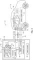
- system 10 for use in charging an electrically powered vehicle 12 is illustrated.
- system 10 includes a charging station 14 coupled to electrically powered vehicle 12.
- Electrically powered vehicle 12 includes at least one energy storage device 16 coupled to motor 18.
- Energy storage device 16 may include, for example, one or more batteries, capacitors, inductors, etc.
- electrically powered vehicle 12 includes a vehicle control circuit 20 coupled to energy storage device 16.
- Vehicle control circuit 20 communicates with charging station 14 and participates in controlling energy transfer from charging station 14 to energy storage device 16.
- vehicle control circuit 20 includes a pilot diode 22, resistors 24 and 26, and a switching device 28.
- the pilot diode 22 on electric vehicle 12 is intended to be a common small signal silicon diode, with reverse voltage ratings of at least 100V being recommended since this diode is exposed directly to cable transients.
- Switching device 28 may be a mechanical switch or relay, or alternatively may be a solid-state switch such as a FET.
- Charging conduit 30 may couple to vehicle 12 at a charging receptacle 32 via a connector 34 that, according to one embodiment, may be a five-prong (not shown) connector compliant with the SAE J1772 standard, with contacts 1 and 2 being used for the AC power lines, contact 3 being used for the equipment ground, contact 4 being used for the control pilot signal (state voltage and reference signal), and contact 5 being used for proximity detection, for example.
- a connector 34 may be a five-prong (not shown) connector compliant with the SAE J1772 standard, with contacts 1 and 2 being used for the AC power lines, contact 3 being used for the equipment ground, contact 4 being used for the control pilot signal (state voltage and reference signal), and contact 5 being used for proximity detection, for example.
- charging conduit 30 may include at least one conductor for supplying electrical energy to energy storage device 16 and/or to any other component within vehicle 12, and at least one conductor for transmitting information to and/or receiving information from vehicle control circuit 20 and/or any other component within vehicle 12. Additionally, or alternatively, charging conduit 30 may include a cable with one or more conductors for supplying electricity to vehicle 12, without a separate and dedicated conductor for communicating information to/from vehicle 12. In such an embodiment, information may be embedded in one or more power signals transmitted through charging conduit 30 between vehicle charging station 14 and vehicle 12.
- charging station 14 includes a power source 36 and a charging device 38 coupled to power source 36.
- charging device 38 includes a processor 44, a state drive circuit 46 coupled to processor 44, and a detection circuit 48 coupled to each of processor 44 and state drive circuit 46.
- Processor 44 includes a memory 50 that may be integrated with processor 44 or separate from processor 44 in other charging device embodiment.
- State drive circuit is configured to provide a control pilot voltage signal to a node A, so as to provide a state voltage to vehicle control circuit 20.
- state drive circuit 46 is configured to supply +/-12V to node A, with state drive circuit 46 including a positive voltage branch 52 to supply +12V to node A and a negative voltage branch 54 to supply -12V to node A.
- positive voltage branch 52 and negative voltage branch 54 are substantially balanced, such that the response time of each branch 52 and 54 to a state voltage command from processor 44 is substantially the same.
- charging device 38 is configured to control energy transfer from power source 36 to electrically powered vehicle 12 (such as via opening/closing of contactors 51) based on a charging state associated with electrically powered vehicle 12 - with such charging state being determined/confirmed via performing of what are referred to hereafter as a "pilot sequencing test” and/or a “pilot diode test.”
- charging device 38 determines the charging cycle state associated with electrically powered vehicle 12 based on the state voltage provided between and affected by each of charging station 14 and electrically powered vehicle 12. More specifically, the state voltage is a voltage affected by charging device 38 and/or vehicle 12 to indicate the changing cycle state associated with electrically powered vehicle 12.
- detection circuit 48 detects the state voltage
- processor 44 determines the charging state associated with electrically powered vehicle 12 based on the detected state voltage.
- the different electric vehicle charging cycle states that are typically defined, such as by the SAE J1772, are represented by different voltages of the pilot signal, including: state A (an electric vehicle is not connected) that is represented by 12 volts, state B (an electric vehicle is connected but not ready to accept energy, with sub-states B1 and B2 being possible, as will be described later) that is represented by 9 volts, state C (an electric vehicle is connected, is ready to accept energy, and indoor charging area ventilation is not required) that is represented by 6 volts, state D (an electric vehicle is connected, ready to accept energy, indoor charging area ventilation is required) that is represented by 3 volts, state E (the charging station is disconnected, utility power is not available, or other charging station problem) that is represented by 0 volts, and state F (charging station is not available, or other charging station problem) that is represented by -12 volts.
- state A an electric vehicle is not connected
- state B an electric vehicle is connected but not ready to accept energy, with sub-states B1 and B2 being
- the stated values are approximate voltages and that, in practice, standards allow for a tolerance of several tenths of a volt (e.g., up to +/- 0.7V) from the stated/nominal values, i.e., the voltages may be equal to or substantially equal to the stated 0V/3V/6 /9 V/12V values, such that more expensive/precise components are not required.
- processor 44 In operation of charging station 14, processor 44 provides a state voltage command, which may be either high (e.g., 0V) or low (e.g., 5V), to state drive circuit 46. Absent a condition to provide a low state voltage command (e.g., an error, a failure, a test, etc.), processor 44 provides a high state voltage command, resulting in state drive circuit 46 supplying a +12V control pilot voltage signal to node A.
- a state voltage command which may be either high (e.g., 0V) or low (e.g., 5V)
- Absent a condition to provide a low state voltage command e.g., an error, a failure, a test, etc.
- processor 44 provides a high state voltage command, resulting in state drive circuit 46 supplying a +12V control pilot voltage signal to node A.
- the processor 44 determines an appropriate pre-charge testing scheme to employ for ensuring that charging may be safely provided, as will be explained in greater detail below - with a more detailed explanation of the pilot sequencing test and pilot diode test that may be performed by processor 44 being described first here below.
- the sequencing test proceeds from a state where the electric vehicle 12 is not connected to charging station 14 (state A) to a state where the vehicle 12 is connected to charging station 14.
- state A a state where the electric vehicle 12 is not connected to charging station 14
- diode 22 and resistor 24 are coupled to charging device 38 and, when the state voltage command is high, the state voltage at node A is thus reduced from +12V to +9V.
- processor 44 determines that vehicle 12 is coupled to charging station 104, but not ready to accept energy (state B). Once processor 44 determines that vehicle 12 is coupled to charging station 14, processor 44 provides a PWM state voltage command to state drive circuit 46 to initiate energy transfer from charging station 14 to vehicle 12.
- PWM state voltage command causes the state drive circuit (via oscillator 56) to generate a control pilot voltage signal that oscillates at a duty cycle equivalent to a 16A charging level, with the pilot voltage signal being a +9V, -12V, 1 KHz square wave, for example.
- the frequency of the oscillating signal is used to verify connection between a compatible electric vehicle 12 and charging station 14, with the vehicle responding to a correct frequency signal by vehicle control circuit 20 closing switch 28 to couple resistor 24 in parallel with resistor 26.
- the parallel combination of resistors 24 and 26 performs as a voltage divider as described above.
- the resulting state voltage is either 6V, indicating vehicle 12 is connected and ready to receive energy without ventilation, or 3V, indicating vehicle 12 is connected and ready to receive energy with ventilation.
- detection circuit 48 detects the state voltage and processor 44 determines the charging state associated with electrically powered vehicle 12, and if it determines that a 6V/3V signal is present, then contactors 51 may be closed to enable charging (state C).
- the processor 44 may determine that only a pilot diode test is needed - without any sequencing requirement. In an occurrence where the state voltage at node A is reduced from +12V to +6V upon connection of vehicle 12 to charging station 14, the processor 44 may determine that only a simplified charging is required (i.e., a jumping from state A to state C, without sequencing requirements). Thus, based on the +6V state voltage at node A, processor 44 performs a self-test to check that an appropriate/compliant electric vehicle 12. Specifically, processor 44 performs a pilot diode test that causes state drive circuit 46 to supply -12V to node A. At the same time, positive voltage branch 52 is turned OFF to stop supplying +12V to node A.
- vehicle control circuit 20 includes diode 22, which blocks the -12V state voltage at node A. Accordingly, resistor 24 is not permitted to behave as a voltage divider with state drive circuit 46 (i.e., a resistor in the state drive circuit). As a result, the -12V state voltage supplied by state drive circuit 46 remains -12V, despite being coupled to vehicle 12.
- Processor 44 receives the - 12V detect signal and confirms that the -12V test is passed. Conversely, if the -12V detect signal is not received, processor 44 recognizes a fault condition.
- the pilot diode test performed by charging device thus ensures an appropriate electric vehicle (that includes a pilot diode 22) is connected to charging station 14 and that the pilot diode 22 is functional, thus helping to prevent misuse of the charging station 14, such as attempting to charge a device other than vehicle 12 from charging station 14.
- the self-test may include one or more other tests, such as, without limitation, a ground fault test.
- charging device 38 operates to control energy transfer from power source 36 to electrically powered vehicle 12 based on a charging cycle state associated with electrically powered vehicle 12, with the charging device 38 sourcing a control pilot signal that is used to perform one or more of the following functions: verify that an electric vehicle is present and connected to the charging station 14, permit energization/de-energization of the power supply 36, transmit available supply current to the electric vehicle 12, and monitor the presence of ground.
- the charging station will often default to employing both a pilot diode test and a pilot sequencing test prior to enabling charging of electric vehicle, but it is recognized that in some instances the performing of both tests is not necessary to enable charging. That is, IEC standards make provision for smaller electric vehicles that draw less than 16A to utilize a "simplified control pilot circuit" - and for such vehicles, performing of the sequencing test is not required such that a "simplified charging” might instead be performed. While the charging station may be configurable to allow for manual/owner designated disabling of one or both of the sequencing test and pilot diode test, such configuring may be problematic and/or inefficient.
- the charging station is a public charging station
- many different types of vehicles i.e., both vehicles that require standard charging and vehicles that only require simplified charging
- an exemplary embodiment of the charging station 14 includes an automated testing scheme or technique performed thereby whereby the charging station selectively performs a sequencing test or pilot diode test based on identified requirements and specifications of the electric vehicle that requests charging from the charging station.
- FIG. 4 a technique 60 is illustrated for such an automated testing scheme or technique. While technique 60 is described with reference to charging station 14, it should be appreciated that technique 60 is not limited to charging station 14 and may be used with other charging station embodiments. In describing the technique 60, reference is made back to FIG. 3 to refer to the components of the charging station 14, as it is recognized that the technique 60 would be implemented by charging device 38 of the charging station 14.
- the processor 44, state drive circuit 46, and detection circuit 48 may perform one or more steps directed to state voltage generation and detection and charging state identification and verification to facilitate implementing of the technique 60.
- the technique 60 begins at STEP 62 at a State A where the electric vehicle 12 is disconnected from the charging station 14. During this time, processor 44 is providing a high state voltage command (i.e., "control pilot signal") to state drive circuit 46, resulting in state drive circuit 46 supplying +/-12V to node A. As long as a +12V control pilot signal is received back by detection circuit 48 (i.e., +12V detect signal), processor 44 determines that no electric vehicle or other load is connected to charging station 14. At STEP 64, an electric vehicle 12 is connected to the charging station 14, during which time the charging station 14 continues to supply a control pilot voltage signal to the electric vehicle 12 via state voltage circuit 46.
- control pilot signal i.e., +12V detect signal
- charging station 14 is able to determine that the connector 34 is fully inserted into the vehicle receptacle 32 and properly connected to the electric vehicle 12 by sensing resistance of resistor 24, as resistor 24 will cause a drop in the detect signal voltage that is sensed by detection circuit 48.
- a determination is then made at STEP 66 of the specific state voltage present at node A resulting from the connection of electric vehicle 12. Specifically, it is determined whether the resulting state voltage at node A is either 6V or 9V, with it being recognized that the voltage present at node A is determined in part based on the configuration of the electric vehicle 12 and the vehicle control circuit 20 included therein.
- switch 28 may be excluded from vehicle control circuit 20 (i.e., a simplified control pilot circuit), as compared to an electric vehicle 12 that draws more than 16A and includes switch 28 as part of vehicle control circuit 20.
- control pilot voltage at node A that is measured/determined at STEP 66 will vary based on the type of electric vehicle 12 connected to the charging station 14 - with a 9V being present at node A for a larger electric vehicle drawing more than 16A (due to switch 28 therein being open at this stage) and 6V (or 3V for state D charging) being present at node A for a smaller electric vehicle drawing less than 16A (due to there being no switch 28 therein - equivalent to a closed switch)
- This variance in the voltage at node A is based on whether resistors 24 and 26 in vehicle control circuit 20 are connected in parallel to act as a voltage divider - with the presence of an open switch 28 or no switch dictating whether such a parallel connection is present.
- technique 60 continues at STEP 70 by identifying that a smaller electric vehicle drawing less than 16A is connected to charging station 14 - such that a simplified charging may be performed to charge electric vehicle 12. That is, in a simplified charging, a stage A --> stage C jump would be performed rather than a typical stage A --> stage B --> stage C sequencing. Based on the determination that a simplified charging technique may be employed to charge electric vehicle 12, it is recognized that a pilot sequencing test is not required, and thus the technique 60 continues at STEP 72 by performing only a pilot diode test.
- processor 44 performs a pilot diode test by causing state drive circuit 46 to supply -12V to node A via negative voltage branch 54 (with positive voltage branch 52 being turned OFF to stop supplying +12V to node A while the -12V is being supplied). Assuming that diode 22 in vehicle control circuit 20 is functioning properly, diode 22 acts to block the -12V state voltage at node A and resistor 24 is not permitted to behave as a voltage divider with state drive circuit (i.e., a resistor in the state drive circuit). Accordingly, the -12V state voltage supplied by state drive circuit 46 remains -12V, despite being coupled to vehicle 12.
- the technique 60 thus proceeds to STEP 78 where the state drive circuit 46 functions to oscillate the control pilot signal as an indication that the charging station 14 is ready to provide charging to the electric vehicle 12. That is, processor 44 causes state drive circuit 46 (i.e., oscillator 56 thereof) to provide a PWM state voltage command to initiate energy transfer from charging station 14 to vehicle 12.
- PWM state voltage command oscillates at a duty cycle equivalent to a 16A charging level, such as at 1 kHz.
- the charging station 14 then closes contactors 51 in charging device 38 such that charging power may be provided from charging station 14 to electric vehicle 12 - with a state C thus being entered into.
- the charging station 14 is thus able to progress from state A directly to state C while only performing the pilot diode test and performing the simplified charging of the electric vehicle at less than 16A.
- the -12V detect signal is not blocked by a functioning diode 22 at node A, then the -12V detect signal would not be received by processor 44, and processor 44 determines that the pilot diode test has not passed, as indicated at 82. A fault condition will thus be identified at STEP 84, and charging of the electric vehicle via charging station 14 is disabled - with a state F thus being entered into.
- technique 60 continues at STEP 88 by identifying that a larger electric vehicle drawing more than 16A is connected to charging station 14 - such that a normal charging sequencing (i.e., not a simplified charging) is required to charge electric vehicle 12.
- processor 44 causes state drive circuit 46 (i.e., oscillator 56 thereof) to oscillate the control pilot signal and provide a PWM state voltage command to initiate energy transfer from charging station 14 to vehicle 12 - such that the charging electric vehicle 12 progresses to a stage B2.
- state drive circuit 46 i.e., oscillator 56 thereof
- PWM state voltage command oscillates at 1 kHz.
- switch 28 When energy transfer is initiated upon oscillation of the control pilot signal, vehicle controller 20 closes switch 28 at STEP 92. Closing of switch 28 couples resistor 24 in parallel with resistor 26 so as to indicate that the electric vehicle is ready to accept energy from the charging station. That is, upon closing of switch 28, the parallel combination of resistors 24 and 26 performs as a voltage divider as described above, such that the state voltage drops to either 6V, indicating vehicle 12 is connected and ready to receive energy without ventilation, or 3V, indicating vehicle 12 is connected and ready to receive energy with ventilation.
- the processor 44 checks the control pilot voltage to verify that it is at one of the expected 6V or 3V levels - indicating that the electric vehicle 12 is ready and able to except charging power from the charging station 14.
- step 92 If the check at STEP 92 indicates that the control pilot voltage to verify that it is at one of the expected 6V or 3V levels, as indicated at 94, then technique continues to STEP 80 where the charging station 14 then closes contactors 51 in charging device 38 such that charging power may be provided from charging station 14 to electric vehicle 12 - with a state C thus being entered into. Conversely, if the check at STEP 92 indicates that the control pilot voltage is not at one of the expected 6V or 3V levels, as indicated at 96, then technique continues to STEP 84, where processor 44 determines that a fault condition is present in the charging station 14 and/or electric vehicle. A fault condition is thus declared at STEP 98 and charging of the electric vehicle 12 via charging station 14 is disabled - with a state F thus being entered into.
- technique 60 continues directly to STEP 84 where processor 44 determines that a fault condition is present in the charging station 14 and/or electric vehicle. A fault condition is thus declared at STEP 84 and charging of the electric vehicle 12 via charging station 14 is disabled - with a state F thus being entered into.
- embodiments of the invention thus provide an electric vehicle charging station and method of operation thereof that prevents misuse of the electric vehicle charging station in providing charging power to an electric vehicle.
- the automated pre-charge testing procedure performed by the charging station provides a flexible charging authorization that accommodates differing types of electric vehicles, as well providing for either AC or DC charging, while meeting desirable safety and efficiency standards.
- the charging station performs an automated check of the electric vehicle requesting charging and determines an appropriate pre-charge testing procedure for authorizing/enabling charging of the electric vehicle based on this check.
- a technical effect of the methods, systems, and apparatus described herein is that a computer implemented technique is provided that includes: identifying parameters of an electric vehicle connected to a charging station and requesting charging therefrom, automatically determining an appropriate pre-charge testing procedure for authorizing/enabling charging of the electric vehicle based on the identified parameters, and ensuring compliance with the selected pre-charge test procedure to confirm that charging of the electric vehicle may proceed.
- a charging station for charging an electrically powered vehicle comprising one or more energy storage devices and a vehicle control circuit having a pilot diode.
- the charging station includes a power source useable to provide recharging power to the one or more energy storage devices on the electrically powered vehicle and a charging device configured to control energy transfer from the power source to the electrically powered vehicle.
- the charging device is configured to provide a control pilot signal to a vehicle control circuit of the electrically powered vehicle, with the control pilot signal being received by the vehicle control circuit upon connection of the electrically powered vehicle to the charging station.
- the charging device is also configured to measure a voltage level of the control pilot signal upon connection of the electrically powered vehicle to the charging station, perform a selected pre-charge testing routine based on the measured voltage level of the control pilot signal, and enable charging of the electrically powered vehicle from the power source upon compliance with the selected pre-charge testing routine that was performed.
- a method of pre-charge testing for authorizing use of an electric vehicle charging station is performed by a charging device of the electric vehicle charging station.
- the method includes providing a control pilot signal to a load upon detecting connection thereof to the electric vehicle charging station and determining a state of a load charging cycle based on the control pilot signal, the load charging cycle comprising at least a State A, a State B, and a State C each defined by a different control pilot signal voltage level.
- the method also includes performing a pilot sequencing test if the charging cycle goes from State A to State B upon connection of the load to the electric vehicle charging station, performing a pilot diode test if the charging cycle goes from State A to State C upon connection of the load to the electric vehicle charging station, and enabling charging of the load from the electric vehicle charging station upon completion of and compliance with the one of the pilot sequencing test or the pilot diode test that was performed.
- a charging station for charging an electrically powered vehicle.
- the charging station includes a state drive circuit configured to generate and provide a control pilot signal to a vehicle control circuit of the electrically powered vehicle, a detection circuit configured to measure a voltage level of the control pilot signal responsive to the providing thereof to the vehicle control circuit, and a processor programmed to determine a charging state associated with the electrically powered vehicle based on the measured voltage level of the control pilot signal, perform a first pre-charge testing routine if the voltage level of the control pilot signal is at a first voltage level or a second pre-charge testing routine if the voltage level of the control pilot signal is at a second voltage level, and enable charging of the electrically powered vehicle from the charging station upon completion of and compliance with the one of the first pre-charge testing routine or the second pre-charge testing routine that was performed.
Landscapes
- Engineering & Computer Science (AREA)
- Power Engineering (AREA)
- Transportation (AREA)
- Mechanical Engineering (AREA)
- Electric Propulsion And Braking For Vehicles (AREA)
- Charge And Discharge Circuits For Batteries Or The Like (AREA)
Claims (15)
- Ladestation (14) zum Laden eines elektrisch angetriebenen Fahrzeugs (12), umfassend eine oder mehrere Energiespeicher-Vorrichtungen (16) und einen Fahrzeug-Steuerkreis (20) mit einer Pilotdiode (22), wobei die Ladestation (14) Folgendes umfasst:eine Stromquelle (36), die verwendbar ist, um Wiederauflade-Energie für die eine oder mehreren Energiespeicher-Vorrichtung(en) (16) am elektrisch angetriebenen Fahrzeug (12) bereitzustellen; undeine Ladevorrichtung (38), die konfiguriert ist, um Energieübertragung von der Stromquelle (36) zum elektrisch angetriebenen Fahrzeug (12) zu steuern, wobei die Ladevorrichtung (38) für Folgendes konfiguriert ist:Bereitstellen eines Steuer-Pilotsignals an einem Fahrzeug-Steuerkreis (20) des elektrisch angetriebenen Fahrzeugs (12), wobei das Steuer-Pilotsignal bei der Verbindung des elektrisch angetriebenen Fahrzeugs (12) mit der Ladestation (14) vom Fahrzeug-Steuerkreis (20) empfangen wird;Messen eines Spannungspegels des Steuer-Pilotsignals bei der Verbindung des elektrisch angetriebenen Fahrzeugs (12) mit der Ladestation (14); dadurch gekennzeichnet, dass die Ladestation für Folgendes konfiguriert ist:Ausführen einer von einer ersten Vorlade-Testroutine und einer zweiten Vorlade-Testroutine, wobei die eine der ersten Vorlade-Testroutine und der zweiten Vorlade-Testroutine auf der Grundlage des gemessenen Spannungspegels des Steuer-Pilotsignals ausgewählt wird; undFreigeben des Ladens des elektrisch angetriebenen Fahrzeugs (12) von der Stromquelle (36) bei Vereinbarkeit mit der einen der ausgeführten ersten Vorlade-Testroutine und zweiten Vorlade-Testroutine.
- Ladestation (14) nach Anspruch 1, wobei die Ladevorrichtung (38) ferner für Folgendes konfiguriert ist:Bestimmen eines dem elektrisch angetriebenen Fahrzeug (12) zugeordneten Ladezyklus-Zustands auf der Grundlage des gemessenen Spannungspegels des Steuer-Pilotsignals;Ausführen der ersten Vorlade-Testroutine, falls der Spannungspegel des Steuer-Pilotsignals bei einem ersten Spannungspegel liegt, oder der zweiten Vorlade-Testroutine, falls der Spannungspegel des Steuer-Pilotsignals bei einem zweiten Spannungspegel liegt, und Freigeben des Ladens des elektrisch angetriebenen Fahrzeugs (12) von der Stromquelle (36) bei Abschluss von und Vereinbarkeit mit der einen der ausgeführten ersten Vorlade-Testroutine oder zweiten Vorlade-Testroutine.
- Ladestation (14) nach Anspruch 2, wobei der erste Spannungspegel etwa 9 V beträgt, wobei der Spannungspegel von etwa 9 V des Steuer-Pilotsignals anzeigt, dass ein Schalter (28) im Fahrzeug-Steuerkreis (20) vorhanden und offen ist, und/oder wobei die erste Vorlade-Testroutine einen Pilot-Sequenzierungstest umfasst, der einer Sequenz Zustand A-> Zustand B --> Zustand C- folgt, wobei jeder Zustand durch einen jeweiligen Spannungspegel des Steuerpilotsignals definiert ist, wobei der Spannungspegel des Steuerpilotsignals zwischen jedem Zustand variiert.
- Ladestation (14) nach Anspruch 3, wobei das Ladegerät (38) beim Ausführen des Pilot-Sequenzierungstests für Folgendes konfiguriert ist:Oszillieren des am Fahrzeug-Steuerkreis (20) bereitgestellten Steuer-Pilotsignals, wobei das oszillierende Steuer-Pilotsignal bewirkt, dass sich der Schalter (28) im Fahrzeug-Steuerkreis (20) schließt;Messen des Spannungspegels des Steuer-Pilotsignals beim Schließen des Schalters (28) im Fahrzeug-Steuerkreis (20);Bewirken, dass sich Schütze (51) in der Ladevorrichtung (38) schließen, falls der Spannungspegel des Steuer-Pilotsignals bei einem dritten Spannungspegel liegt, um das Laden des elektrisch angetriebenen Fahrzeugs (12) von der Stromquelle (36) freizugeben, wobei der dritte Spannungspegel entweder etwa 3 V oder etwa 6 V beträgt;andernfalls Erklären eines Fehlerzustands und Sperren des Ladens des elektrisch angetriebenen Fahrzeugs (12) von der Stromquelle (36).
- Ladestation (14) nach Anspruch 2, wobei der zweite Spannungspegel etwa 3 V oder etwa 6 V beträgt, wobei der Spannungspegel des Steuer-Pilotsignals von etwa 3 V oder 6 V anzeigt, dass der Fahrzeug-Steuerkreis (20) einen vereinfachten Fahrzeug-Steuerkreis (20) umfasst, der keinen Schalter (28) darin besitzt, und/oder wobei die zweite Vorlade-Testroutine einen Pilotdioden-Test umfasst, der einer Sequenz Zustand A --> Zustand C folgt, wobei jeder Zustand durch einen jeweiligen Spannungspegel des Steuer-Pilotsignals definiert ist, wobei der Spannungspegel des Steuerpilotsignals zwischen jedem Zustand variiert.
- Ladestation (14) nach Anspruch 5, wobei das Ladegerät (38) beim Ausführen des Pilotdioden-Tests für Folgendes konfiguriert ist:Bereitstellen eines Steuer-Pilotsignals mit einer Spannung von -12 V an dem Fahrzeug-Steuerkreis (20);Messen des Spannungspegels des Steuer-Pilotsignals als Reaktion auf das Bereitstellen des Steuer-Pilotsignals am Fahrzeug-Steuerkreis (20);Oszillieren des am Fahrzeug-Steuerkreis (20) bereitgestellten Steuer-Pilotsignals und Bewirken, dass sich Schütze (51) in der Ladevorrichtung (38) schließen, falls der Spannungspegel des Steuer-Pilotsignals bei etwa -12 V verbleibt; wobei die Ladevorrichtung (38) konfiguriert ist, um das Steuer-Pilotsignal mit einer Einschaltdauer zu oszillieren, die einem Ladepegel von 16 A entspricht;andernfalls Erklären eines Fehlerzustands und Sperren des Ladens des elektrisch angetriebenen Fahrzeugs (12) von der Stromquelle (36).
- Ladestation (14) nach Anspruch 2, wobei die Ladevorrichtung (38) konfiguriert ist, um einen Fehlerzustand zu melden und das Laden des elektrisch angetriebenen Fahrzeugs (12) von der Stromquelle (36) zu sperren, falls der Spannungspegel des Steuer-Pilotsignals bei der Verbindung des elektrisch angetriebenen Fahrzeugs (12) mit der Ladestation (14) weder auf dem ersten Spannungspegel noch auf dem zweiten Spannungspegel ist.
- Ladestation (14) nach Anspruch 1, wobei die Ladevorrichtung (38) Folgendes umfasst:einen Zustands-Treiberkreis (46), der konfiguriert ist, um das Steuer-Pilotsignal zu erzeugen;ein Detektionskreis (48), der konfiguriert ist, um als Reaktion auf das Bereitstellen des Spannungspegels des Steuer-Pilotsignals am Fahrzeug-Steuerkreis (20) diesen zu messen; undeinen Prozessor (44), der programmiert ist, um dem Zustands-Treiberkreis (46) Befehle bereitzustellen, welche die Erzeugung des Steuer-Pilotsignals steuern und das Laden des elektrisch angetriebenen Fahrzeugs (12) von der Stromquelle (36) freigeben und sperren.
- Verfahren zum Laden eines elektrisch angetriebenen Fahrzeugs (12), umfassend eine oder mehrere Energiespeicher-Vorrichtungen (16) und einen Fahrzeug-Steuerkreis (20) mit einer Pilotdiode (22), wobei die Ladestation (14) eine Stromquelle (36) umfasst, die verwendbar ist, um Wiederauflade-Energie für die eine oder mehreren Energiespeicher-Vorrichtung(en) (16) am elektrisch angetriebenen Fahrzeug (12) bereitzustellen, sowie eine Ladevorrichtung (38), die konfiguriert ist, um Energieübertragung von der Stromquelle (36) zum elektrisch angetriebenen Fahrzeug zu steuern (12), wobei das Verfahren durch Folgendes gekennzeichnet ist:Bereitstellen eines Steuer-Pilotsignals an einem Fahrzeug-Steuerkreis (20) des elektrisch angetriebenen Fahrzeugs (12), wobei das Steuer-Pilotsignal bei der Verbindung des elektrisch angetriebenen Fahrzeugs (12) mit der Ladestation (14) vom Fahrzeug-Steuerkreis (20) empfangen wird;Messen eines Spannungspegels des Steuer-Pilotsignals bei der Verbindung des elektrisch angetriebenen Fahrzeugs (12) mit der Ladestation (14); undAusführen einer von einer ersten Vorlade-Testroutine und einer zweiten Vorlade-Testroutine, wobei die eine der ersten Vorlade-Testroutine und der zweiten Vorlade-Testroutine auf der Grundlage des gemessenen Spannungspegels des Steuer-Pilotsignals ausgewählt wird; undFreigeben des Ladens des elektrisch angetriebenen Fahrzeugs (12) von der Stromquelle (36) bei Vereinbarkeit mit der einen der ausgeführten ersten Vorlade-Testroutine und zweiten Vorlade-Testroutine.
- Verfahren nach Anspruch 9, umfassend:Bestimmen eines dem elektrisch angetriebenen Fahrzeug (12) zugeordneten Ladezyklus-Zustands auf der Grundlage der gemessenen Spannung des Steuer-Pilotsignals, wobei der Ladezyklus-Zustand zumindest einen eines Zustands A, eines Zustands B oder eines Zustands C umfasst, die jeweils durch einen unterschiedlichen Spannungspegel des Steuer-Pilotsignals definiert sind;Ausführen eines Pilot-Sequenzierungstests als die erste Vorlade-Testroutine, falls der Ladezyklus bei der Verbindung der Last mit der Elektrofahrzeug-Ladestation (14) von Zustand A zu Zustand B übergeht; undAusführen eines Pilotdioden-Tests als die zweite Vorlade-Testroutine, falls der Ladezyklus bei der Verbindung der Last mit der Elektrofahrzeug-Ladestation (14) von Zustand A zu Zustand C übergeht.
- Verfahren nach Anspruch 10, wobei der Ladezyklus in Zustand B ist, wenn der Spannungspegel des Steuer-Pilotsignals etwa 9 V beträgt, wobei der Spannungspegel des Steuer-Pilotsignals von 9 V anzeigt, dass ein Schalter (28) im Fahrzeug-Steuerkreis (20) vorhanden ist und der Schalter (28) in einem offenen Zustand ist, um das Laden der Last bei einem Ladepegel von 16 A oder höher bereitzustellen, und wobei der Ladezyklus-Zustand im Zustand C ist, wenn der Spannungspegel des Steuer-Pilotsignals ungefähr 6 V beträgt.
- Verfahren nach Anspruch 10, wobei das Ausführen des Pilot-Sequenzierungstests Folgendes umfasst:Oszillieren des am Fahrzeug-Steuerkreis (20) bereitgestellten Steuer-Pilotsignals, wobei das oszillierende Steuer-Pilotsignal bewirkt, dass sich der Schalter (28) im Fahrzeug-Steuerkreis (20) schließt;Messen des Spannungspegels des Steuer-Pilotsignals beim Schließen des Schalters (28) im Fahrzeug-Steuerkreis (20);Bewirken, dass sich Schütze (51) in der Ladevorrichtung (38) schließen, falls der gemessene Spannungspegel des Steuer-Pilotsignals beim Schließen des Schalters (28) im Fahrzeug-Steuerkreis etwa 6 V beträgt, um das Laden des elektrisch angetriebenen Fahrzeugs (12) freizugeben;andernfalls Erklären eines Fehlerzustands und Sperren des Ladens des elektrisch angetriebenen Fahrzeugs (12) von der Stromquelle (36).
- Verfahren nach Anspruch 12, wobei der Spannungspegel des Steuer-Pilotsignals von 6 V anzeigt, dass der Fahrzeug-Steuerkreis einen vereinfachten Fahrzeug-Steuerkreis (20) umfasst, der keinen Schalter (28) darin besitzt, wenn der Ladezyklus von Zustand A zu Zustand C springt, um ein Laden des elektrisch angetriebenen Fahrzeugs (12) bei einem Ladepegel von 16 A oder höher bereitzustellen; und
wobei der Spannungspegel des Steuer-Pilotsignals von 6 V anzeigt, dass das elektrisch angetriebene Fahrzeug (12) einen Fahrzeug-Steuerkreis (20) mit dem Schalter (28) in einem geschlossenen Zustand umfasst, wenn der Ladezyklus von Zustand B zu Zustand C übergeht, um ein Laden des elektrisch angetriebenen Fahrzeugs (12) bei einem Ladepegel von 16 A oder höher bereitzustellen. - Verfahren nach Anspruch 12, wobei das Ausführen des Pilotdioden-Tests Folgendes umfasst:Bereitstellen eines Steuer-Pilotsignals an dem Fahrzeug-Steuerkreis (20) mit einer Spannung von -12 V an der Last;Messen des Spannungspegels des Steuer-Pilotsignals als Reaktion auf das Bereitstellen des Steuer-Pilotsignals von -12 V am Fahrzeug-Steuerkreis (20);Oszillieren des Steuer-Pilotsignals und Bewirken, dass sich Schütze (51) in der Ladevorrichtung (38) schließen, falls der Spannungspegel des Steuer-Pilotsignals bei etwa - 12 V verbleibt;andernfalls Erklären eines Fehlerzustands und Sperren des Ladens des elektrisch angetriebenen Fahrzeugs (12) von der Stromquelle (36).
- Verfahren nach Anspruch 14, wobei das Steuer-Pilotsignal als Teil des Pilotdioden-Tests mit einer Einschaltdauer oszilliert wird, die einem Ladepegel von 16 A entspricht, wenn der Ladezyklus von Zustand A zu Zustand C springt.
Applications Claiming Priority (1)
| Application Number | Priority Date | Filing Date | Title |
|---|---|---|---|
| US15/830,322 US10882415B2 (en) | 2017-12-04 | 2017-12-04 | System and method of pre-charge testing to prevent misuse of electric vehicle charging station |
Publications (2)
| Publication Number | Publication Date |
|---|---|
| EP3498523A1 EP3498523A1 (de) | 2019-06-19 |
| EP3498523B1 true EP3498523B1 (de) | 2023-05-10 |
Family
ID=64556698
Family Applications (1)
| Application Number | Title | Priority Date | Filing Date |
|---|---|---|---|
| EP18208752.8A Active EP3498523B1 (de) | 2017-12-04 | 2018-11-28 | System und verfahren für vorladetests zur verhinderung des missbrauchs einer ladestation für elektrofahrzeuge |
Country Status (4)
| Country | Link |
|---|---|
| US (1) | US10882415B2 (de) |
| EP (1) | EP3498523B1 (de) |
| JP (2) | JP7313814B2 (de) |
| CN (1) | CN109866646B (de) |
Families Citing this family (12)
| Publication number | Priority date | Publication date | Assignee | Title |
|---|---|---|---|---|
| DE102020100955A1 (de) | 2020-01-16 | 2021-07-22 | Audi Aktiengesellschaft | Ladeverfahren für ein Elektrofahrzeug |
| TW202130527A (zh) * | 2020-02-04 | 2021-08-16 | 飛宏科技股份有限公司 | 直流充電樁中偵測控制導引點異常的電路及其方法 |
| US11385631B2 (en) * | 2020-11-11 | 2022-07-12 | Honda Research Institute Europe Gmbh | Method and system for detecting faults in a charging infrastructure system for electric vehicles |
| CN112895961B (zh) * | 2021-01-29 | 2023-05-05 | 北京嘀嘀无限科技发展有限公司 | 交通工具的充电验证的方法和装置 |
| KR20230024147A (ko) * | 2021-08-11 | 2023-02-20 | 현대자동차주식회사 | 자율 이동장치, 도킹 스테이션 및 자율 이동장치의 제어방법 |
| KR20230024148A (ko) | 2021-08-11 | 2023-02-20 | 현대자동차주식회사 | 이동장치를 위한 도킹 스테이션의 유체 공급 시스템 및 그 제어방법 |
| US12208701B2 (en) * | 2021-11-08 | 2025-01-28 | Honda Motor Co., Ltd. | System and method for identifying an electric vehicle through alternating current electric charging |
| EP4201735A3 (de) * | 2021-12-22 | 2023-07-26 | PhySens GmbH | Adapter und ladesystem |
| TWI849402B (zh) * | 2022-04-08 | 2024-07-21 | 飛宏科技股份有限公司 | 直流充電樁中控制導引點異常的偵測電路 |
| CN115042644B (zh) * | 2022-05-24 | 2026-04-14 | 中电海康集团有限公司 | 一种电动车充电系统、方法及装置 |
| JP7524513B2 (ja) * | 2022-12-15 | 2024-07-30 | メルセデス・ベンツ グループ アクチェンゲゼルシャフト | 充電器管理装置、及び充電制御装置 |
| US20240326626A1 (en) * | 2023-03-28 | 2024-10-03 | Uchicago Argonne, Llc | Vehicle charging system compatible with multiple charging protocols and method |
Family Cites Families (26)
| Publication number | Priority date | Publication date | Assignee | Title |
|---|---|---|---|---|
| GB1425313A (en) | 1972-03-13 | 1976-02-18 | Baldwin Francis Holdings Ld | Power supply control circuits |
| US5369540A (en) * | 1993-02-11 | 1994-11-29 | General Electric Company | Electric vehicle drive train with contactor protection |
| JP4259006B2 (ja) * | 2001-09-18 | 2009-04-30 | スズキ株式会社 | 電気自動車用電源制御装置 |
| JP4380776B1 (ja) * | 2008-07-25 | 2009-12-09 | トヨタ自動車株式会社 | 充放電システムおよび電動車両 |
| CN102318162B (zh) * | 2009-02-03 | 2013-08-28 | 丰田自动车株式会社 | 车辆的充电系统 |
| DE102009025303A1 (de) | 2009-06-15 | 2010-12-16 | Rwe Ag | Verfahren und Vorrichtung zur Kommunikation zwischen einem Elektrofahrzeug und einer Ladestation |
| JP2011200071A (ja) * | 2010-03-23 | 2011-10-06 | Toyota Motor Corp | 車両の制御装置およびそれを搭載する車両 |
| US8378623B2 (en) * | 2010-11-05 | 2013-02-19 | General Electric Company | Apparatus and method for charging an electric vehicle |
| DE102010063790A1 (de) * | 2010-12-21 | 2012-06-21 | Bayerische Motoren Werke Aktiengesellschaft | Ladestation, Adaptervorrichtung und Ladesystem |
| US9000721B2 (en) * | 2011-06-29 | 2015-04-07 | General Electric Company | Systems and methods for charging |
| US8917054B2 (en) | 2011-08-08 | 2014-12-23 | Lear Corporation | Charger system with safety guardian |
| JP5758746B2 (ja) | 2011-08-30 | 2015-08-05 | トヨタ自動車株式会社 | 給電コネクタ、車両および車両の制御方法 |
| US8466656B2 (en) | 2011-09-09 | 2013-06-18 | General Electric Company | Charging devices and methods for charging electrically powered vehicles |
| US9725005B2 (en) | 2011-12-15 | 2017-08-08 | Chargepoint, Inc. | Circuit for controlling an electric vehicle pilot signal level for connector disconnect |
| US9350187B2 (en) * | 2012-01-09 | 2016-05-24 | Johnson Controls Technology Llc | Pre-charging vehicle bus using parallel battery packs |
| JP5970666B2 (ja) | 2012-05-09 | 2016-08-17 | 株式会社豊田自動織機 | 充電装置 |
| US9333864B2 (en) | 2012-05-31 | 2016-05-10 | Lear Corporation | Wake-by-control pilot circuit for onboard battery charger |
| US9118183B2 (en) * | 2012-06-07 | 2015-08-25 | Schneider Electric USA, Inc. | Auto detection of vehicle type connected to an EVSE |
| JP2014128111A (ja) | 2012-12-26 | 2014-07-07 | Toyota Industries Corp | 充電システム |
| US10286800B2 (en) * | 2013-10-09 | 2019-05-14 | Ford Global Technologies, Llc | Control pilot latch-out mechanism to reduce off-board energy consumption |
| KR101587357B1 (ko) | 2014-09-01 | 2016-01-20 | 엘에스산전 주식회사 | 차량 충전 장치 및 충전 방법 |
| US20160121736A1 (en) * | 2014-10-31 | 2016-05-05 | Schneider Electric USA, Inc. | Evse shorted cable protection method |
| US9804034B2 (en) | 2014-11-14 | 2017-10-31 | Schneider Electric USA, Inc. | EVSE with cordset handle temperature measurement |
| JP6502871B2 (ja) * | 2016-02-12 | 2019-04-17 | 株式会社デンソー | 車両の充電システム及び充電制御装置 |
| CN106564396A (zh) * | 2016-11-03 | 2017-04-19 | 深圳市沃特玛电池有限公司 | 电动汽车及其预充电控制电路 |
| CN106427648B (zh) * | 2016-11-15 | 2018-11-16 | 许继电源有限公司 | 一种充电桩预充电控制方法和装置 |
-
2017
- 2017-12-04 US US15/830,322 patent/US10882415B2/en active Active
-
2018
- 2018-11-28 EP EP18208752.8A patent/EP3498523B1/de active Active
- 2018-12-03 CN CN201811464252.4A patent/CN109866646B/zh active Active
- 2018-12-03 JP JP2018226185A patent/JP7313814B2/ja active Active
-
2023
- 2023-07-12 JP JP2023114795A patent/JP7634927B2/ja active Active
Also Published As
| Publication number | Publication date |
|---|---|
| US20190168619A1 (en) | 2019-06-06 |
| CN109866646B (zh) | 2023-08-25 |
| US10882415B2 (en) | 2021-01-05 |
| EP3498523A1 (de) | 2019-06-19 |
| JP2023139076A (ja) | 2023-10-03 |
| JP7313814B2 (ja) | 2023-07-25 |
| JP2019110744A (ja) | 2019-07-04 |
| CN109866646A (zh) | 2019-06-11 |
| JP7634927B2 (ja) | 2025-02-25 |
Similar Documents
| Publication | Publication Date | Title |
|---|---|---|
| EP3498523B1 (de) | System und verfahren für vorladetests zur verhinderung des missbrauchs einer ladestation für elektrofahrzeuge | |
| CN105480103B (zh) | 高电压电池非车载充电器 | |
| JP5854242B2 (ja) | 電動車両を用いた電力供給装置 | |
| US8768533B2 (en) | Vehicle, communication system, and communication device | |
| CN104553847B (zh) | 具有第二dc-dc转换器的插电式车辆 | |
| US11167657B2 (en) | Vehicle charging system | |
| US9114716B2 (en) | Method and apparatus for high-voltage DC charging of battery-electric and plug-in hybrid electric vehicles | |
| EP2690741B1 (de) | Adapter und fahrzeug sowie verfahren zur stromversorgung damit | |
| EP3092149B1 (de) | Hybridfahrzeug mit einer einrichtung zum abschalten einer abgereicherten hilfsbatterie, um ein schnelleres aufladen der hauptbatterie zu erlauben | |
| JP7528784B2 (ja) | 電力伝送システム | |
| US9296305B2 (en) | Charging apparatus for vehicles | |
| CN113263931A (zh) | 用于利用充电站对车辆充电的导频控制电路 | |
| CN103814498A (zh) | 电动汽车用的充电装置 | |
| CN112428822A (zh) | 一种诊断控制方法、装置及电动汽车 | |
| CN110014889B (zh) | 对具有电驱动器的车辆的低电压车载网络的供电 | |
| US9108522B2 (en) | Vehicle-mounted controller | |
| JP2010142088A (ja) | プラグイン車両用充電システム及び充電制御装置 | |
| CN115912326A (zh) | 车辆控制装置、车辆、电力供给系统、放电连接器、电力设备以及电力供给方法 | |
| US11552486B2 (en) | Portable vehicle charging system with location detection | |
| CN120171355B (zh) | 充放电控制方法、装置、介质及充电桩 | |
| CN219927479U (zh) | 电动车直流充电系统及电动车 | |
| CN121487856A (zh) | 车辆充电装置 | |
| CN119821202A (zh) | 车辆充电控制方法、装置、车辆及存储介质 | |
| CN120073973A (zh) | 车辆中蓄电池充电系统、方法、车载电源模块和车辆 | |
| JPWO2013054435A1 (ja) | 電気自動車用の充電装置 |
Legal Events
| Date | Code | Title | Description |
|---|---|---|---|
| PUAI | Public reference made under article 153(3) epc to a published international application that has entered the european phase |
Free format text: ORIGINAL CODE: 0009012 |
|
| STAA | Information on the status of an ep patent application or granted ep patent |
Free format text: STATUS: THE APPLICATION HAS BEEN PUBLISHED |
|
| AK | Designated contracting states |
Kind code of ref document: A1 Designated state(s): AL AT BE BG CH CY CZ DE DK EE ES FI FR GB GR HR HU IE IS IT LI LT LU LV MC MK MT NL NO PL PT RO RS SE SI SK SM TR |
|
| AX | Request for extension of the european patent |
Extension state: BA ME |
|
| STAA | Information on the status of an ep patent application or granted ep patent |
Free format text: STATUS: REQUEST FOR EXAMINATION WAS MADE |
|
| 17P | Request for examination filed |
Effective date: 20191018 |
|
| RBV | Designated contracting states (corrected) |
Designated state(s): AL AT BE BG CH CY CZ DE DK EE ES FI FR GB GR HR HU IE IS IT LI LT LU LV MC MK MT NL NO PL PT RO RS SE SI SK SM TR |
|
| STAA | Information on the status of an ep patent application or granted ep patent |
Free format text: STATUS: EXAMINATION IS IN PROGRESS |
|
| 17Q | First examination report despatched |
Effective date: 20210416 |
|
| GRAP | Despatch of communication of intention to grant a patent |
Free format text: ORIGINAL CODE: EPIDOSNIGR1 |
|
| STAA | Information on the status of an ep patent application or granted ep patent |
Free format text: STATUS: GRANT OF PATENT IS INTENDED |
|
| INTG | Intention to grant announced |
Effective date: 20221201 |
|
| GRAS | Grant fee paid |
Free format text: ORIGINAL CODE: EPIDOSNIGR3 |
|
| GRAA | (expected) grant |
Free format text: ORIGINAL CODE: 0009210 |
|
| STAA | Information on the status of an ep patent application or granted ep patent |
Free format text: STATUS: THE PATENT HAS BEEN GRANTED |
|
| AK | Designated contracting states |
Kind code of ref document: B1 Designated state(s): AL AT BE BG CH CY CZ DE DK EE ES FI FR GB GR HR HU IE IS IT LI LT LU LV MC MK MT NL NO PL PT RO RS SE SI SK SM TR |
|
| REG | Reference to a national code |
Ref country code: GB Ref legal event code: FG4D |
|
| REG | Reference to a national code |
Ref country code: AT Ref legal event code: REF Ref document number: 1566377 Country of ref document: AT Kind code of ref document: T Effective date: 20230515 Ref country code: CH Ref legal event code: EP |
|
| REG | Reference to a national code |
Ref country code: DE Ref legal event code: R096 Ref document number: 602018049520 Country of ref document: DE |
|
| REG | Reference to a national code |
Ref country code: IE Ref legal event code: FG4D |
|
| P01 | Opt-out of the competence of the unified patent court (upc) registered |
Effective date: 20230528 |
|
| REG | Reference to a national code |
Ref country code: LT Ref legal event code: MG9D |
|
| REG | Reference to a national code |
Ref country code: NL Ref legal event code: MP Effective date: 20230510 |
|
| REG | Reference to a national code |
Ref country code: AT Ref legal event code: MK05 Ref document number: 1566377 Country of ref document: AT Kind code of ref document: T Effective date: 20230510 |
|
| PG25 | Lapsed in a contracting state [announced via postgrant information from national office to epo] |
Ref country code: SE Free format text: LAPSE BECAUSE OF FAILURE TO SUBMIT A TRANSLATION OF THE DESCRIPTION OR TO PAY THE FEE WITHIN THE PRESCRIBED TIME-LIMIT Effective date: 20230510 Ref country code: PT Free format text: LAPSE BECAUSE OF FAILURE TO SUBMIT A TRANSLATION OF THE DESCRIPTION OR TO PAY THE FEE WITHIN THE PRESCRIBED TIME-LIMIT Effective date: 20230911 Ref country code: NO Free format text: LAPSE BECAUSE OF FAILURE TO SUBMIT A TRANSLATION OF THE DESCRIPTION OR TO PAY THE FEE WITHIN THE PRESCRIBED TIME-LIMIT Effective date: 20230810 Ref country code: NL Free format text: LAPSE BECAUSE OF FAILURE TO SUBMIT A TRANSLATION OF THE DESCRIPTION OR TO PAY THE FEE WITHIN THE PRESCRIBED TIME-LIMIT Effective date: 20230510 Ref country code: ES Free format text: LAPSE BECAUSE OF FAILURE TO SUBMIT A TRANSLATION OF THE DESCRIPTION OR TO PAY THE FEE WITHIN THE PRESCRIBED TIME-LIMIT Effective date: 20230510 Ref country code: AT Free format text: LAPSE BECAUSE OF FAILURE TO SUBMIT A TRANSLATION OF THE DESCRIPTION OR TO PAY THE FEE WITHIN THE PRESCRIBED TIME-LIMIT Effective date: 20230510 |
|
| PG25 | Lapsed in a contracting state [announced via postgrant information from national office to epo] |
Ref country code: RS Free format text: LAPSE BECAUSE OF FAILURE TO SUBMIT A TRANSLATION OF THE DESCRIPTION OR TO PAY THE FEE WITHIN THE PRESCRIBED TIME-LIMIT Effective date: 20230510 Ref country code: PL Free format text: LAPSE BECAUSE OF FAILURE TO SUBMIT A TRANSLATION OF THE DESCRIPTION OR TO PAY THE FEE WITHIN THE PRESCRIBED TIME-LIMIT Effective date: 20230510 Ref country code: LV Free format text: LAPSE BECAUSE OF FAILURE TO SUBMIT A TRANSLATION OF THE DESCRIPTION OR TO PAY THE FEE WITHIN THE PRESCRIBED TIME-LIMIT Effective date: 20230510 Ref country code: LT Free format text: LAPSE BECAUSE OF FAILURE TO SUBMIT A TRANSLATION OF THE DESCRIPTION OR TO PAY THE FEE WITHIN THE PRESCRIBED TIME-LIMIT Effective date: 20230510 Ref country code: IS Free format text: LAPSE BECAUSE OF FAILURE TO SUBMIT A TRANSLATION OF THE DESCRIPTION OR TO PAY THE FEE WITHIN THE PRESCRIBED TIME-LIMIT Effective date: 20230910 Ref country code: HR Free format text: LAPSE BECAUSE OF FAILURE TO SUBMIT A TRANSLATION OF THE DESCRIPTION OR TO PAY THE FEE WITHIN THE PRESCRIBED TIME-LIMIT Effective date: 20230510 Ref country code: GR Free format text: LAPSE BECAUSE OF FAILURE TO SUBMIT A TRANSLATION OF THE DESCRIPTION OR TO PAY THE FEE WITHIN THE PRESCRIBED TIME-LIMIT Effective date: 20230811 |
|
| PG25 | Lapsed in a contracting state [announced via postgrant information from national office to epo] |
Ref country code: FI Free format text: LAPSE BECAUSE OF FAILURE TO SUBMIT A TRANSLATION OF THE DESCRIPTION OR TO PAY THE FEE WITHIN THE PRESCRIBED TIME-LIMIT Effective date: 20230510 |
|
| PG25 | Lapsed in a contracting state [announced via postgrant information from national office to epo] |
Ref country code: SK Free format text: LAPSE BECAUSE OF FAILURE TO SUBMIT A TRANSLATION OF THE DESCRIPTION OR TO PAY THE FEE WITHIN THE PRESCRIBED TIME-LIMIT Effective date: 20230510 |
|
| PG25 | Lapsed in a contracting state [announced via postgrant information from national office to epo] |
Ref country code: SM Free format text: LAPSE BECAUSE OF FAILURE TO SUBMIT A TRANSLATION OF THE DESCRIPTION OR TO PAY THE FEE WITHIN THE PRESCRIBED TIME-LIMIT Effective date: 20230510 Ref country code: SK Free format text: LAPSE BECAUSE OF FAILURE TO SUBMIT A TRANSLATION OF THE DESCRIPTION OR TO PAY THE FEE WITHIN THE PRESCRIBED TIME-LIMIT Effective date: 20230510 Ref country code: RO Free format text: LAPSE BECAUSE OF FAILURE TO SUBMIT A TRANSLATION OF THE DESCRIPTION OR TO PAY THE FEE WITHIN THE PRESCRIBED TIME-LIMIT Effective date: 20230510 Ref country code: EE Free format text: LAPSE BECAUSE OF FAILURE TO SUBMIT A TRANSLATION OF THE DESCRIPTION OR TO PAY THE FEE WITHIN THE PRESCRIBED TIME-LIMIT Effective date: 20230510 Ref country code: DK Free format text: LAPSE BECAUSE OF FAILURE TO SUBMIT A TRANSLATION OF THE DESCRIPTION OR TO PAY THE FEE WITHIN THE PRESCRIBED TIME-LIMIT Effective date: 20230510 Ref country code: CZ Free format text: LAPSE BECAUSE OF FAILURE TO SUBMIT A TRANSLATION OF THE DESCRIPTION OR TO PAY THE FEE WITHIN THE PRESCRIBED TIME-LIMIT Effective date: 20230510 |
|
| REG | Reference to a national code |
Ref country code: DE Ref legal event code: R097 Ref document number: 602018049520 Country of ref document: DE |
|
| PLBE | No opposition filed within time limit |
Free format text: ORIGINAL CODE: 0009261 |
|
| STAA | Information on the status of an ep patent application or granted ep patent |
Free format text: STATUS: NO OPPOSITION FILED WITHIN TIME LIMIT |
|
| 26N | No opposition filed |
Effective date: 20240213 |
|
| PG25 | Lapsed in a contracting state [announced via postgrant information from national office to epo] |
Ref country code: SI Free format text: LAPSE BECAUSE OF FAILURE TO SUBMIT A TRANSLATION OF THE DESCRIPTION OR TO PAY THE FEE WITHIN THE PRESCRIBED TIME-LIMIT Effective date: 20230510 |
|
| PG25 | Lapsed in a contracting state [announced via postgrant information from national office to epo] |
Ref country code: SI Free format text: LAPSE BECAUSE OF FAILURE TO SUBMIT A TRANSLATION OF THE DESCRIPTION OR TO PAY THE FEE WITHIN THE PRESCRIBED TIME-LIMIT Effective date: 20230510 |
|
| REG | Reference to a national code |
Ref country code: CH Ref legal event code: PL |
|
| PG25 | Lapsed in a contracting state [announced via postgrant information from national office to epo] |
Ref country code: MC Free format text: LAPSE BECAUSE OF FAILURE TO SUBMIT A TRANSLATION OF THE DESCRIPTION OR TO PAY THE FEE WITHIN THE PRESCRIBED TIME-LIMIT Effective date: 20230510 |
|
| PG25 | Lapsed in a contracting state [announced via postgrant information from national office to epo] |
Ref country code: LU Free format text: LAPSE BECAUSE OF NON-PAYMENT OF DUE FEES Effective date: 20231128 |
|
| PG25 | Lapsed in a contracting state [announced via postgrant information from national office to epo] |
Ref country code: CH Free format text: LAPSE BECAUSE OF NON-PAYMENT OF DUE FEES Effective date: 20231130 |
|
| PG25 | Lapsed in a contracting state [announced via postgrant information from national office to epo] |
Ref country code: MC Free format text: LAPSE BECAUSE OF FAILURE TO SUBMIT A TRANSLATION OF THE DESCRIPTION OR TO PAY THE FEE WITHIN THE PRESCRIBED TIME-LIMIT Effective date: 20230510 Ref country code: LU Free format text: LAPSE BECAUSE OF NON-PAYMENT OF DUE FEES Effective date: 20231128 Ref country code: CH Free format text: LAPSE BECAUSE OF NON-PAYMENT OF DUE FEES Effective date: 20231130 |
|
| REG | Reference to a national code |
Ref country code: BE Ref legal event code: MM Effective date: 20231130 |
|
| REG | Reference to a national code |
Ref country code: IE Ref legal event code: MM4A |
|
| PG25 | Lapsed in a contracting state [announced via postgrant information from national office to epo] |
Ref country code: IE Free format text: LAPSE BECAUSE OF NON-PAYMENT OF DUE FEES Effective date: 20231128 |
|
| PG25 | Lapsed in a contracting state [announced via postgrant information from national office to epo] |
Ref country code: BE Free format text: LAPSE BECAUSE OF NON-PAYMENT OF DUE FEES Effective date: 20231130 |
|
| PG25 | Lapsed in a contracting state [announced via postgrant information from national office to epo] |
Ref country code: IE Free format text: LAPSE BECAUSE OF NON-PAYMENT OF DUE FEES Effective date: 20231128 Ref country code: BE Free format text: LAPSE BECAUSE OF NON-PAYMENT OF DUE FEES Effective date: 20231130 |
|
| PG25 | Lapsed in a contracting state [announced via postgrant information from national office to epo] |
Ref country code: BG Free format text: LAPSE BECAUSE OF FAILURE TO SUBMIT A TRANSLATION OF THE DESCRIPTION OR TO PAY THE FEE WITHIN THE PRESCRIBED TIME-LIMIT Effective date: 20230510 |
|
| PG25 | Lapsed in a contracting state [announced via postgrant information from national office to epo] |
Ref country code: BG Free format text: LAPSE BECAUSE OF FAILURE TO SUBMIT A TRANSLATION OF THE DESCRIPTION OR TO PAY THE FEE WITHIN THE PRESCRIBED TIME-LIMIT Effective date: 20230510 |
|
| PG25 | Lapsed in a contracting state [announced via postgrant information from national office to epo] |
Ref country code: CY Free format text: LAPSE BECAUSE OF FAILURE TO SUBMIT A TRANSLATION OF THE DESCRIPTION OR TO PAY THE FEE WITHIN THE PRESCRIBED TIME-LIMIT; INVALID AB INITIO Effective date: 20181128 |
|
| PG25 | Lapsed in a contracting state [announced via postgrant information from national office to epo] |
Ref country code: HU Free format text: LAPSE BECAUSE OF FAILURE TO SUBMIT A TRANSLATION OF THE DESCRIPTION OR TO PAY THE FEE WITHIN THE PRESCRIBED TIME-LIMIT; INVALID AB INITIO Effective date: 20181128 |
|
| REG | Reference to a national code |
Ref country code: DE Ref legal event code: R081 Ref document number: 602018049520 Country of ref document: DE Owner name: DOLBY INTELLECTUAL PROPERTY LICENSING, LLC, NI, US Free format text: FORMER OWNER: GENERAL ELECTRIC COMPANY, SCHENECTADY, NY, US |
|
| PG25 | Lapsed in a contracting state [announced via postgrant information from national office to epo] |
Ref country code: TR Free format text: LAPSE BECAUSE OF FAILURE TO SUBMIT A TRANSLATION OF THE DESCRIPTION OR TO PAY THE FEE WITHIN THE PRESCRIBED TIME-LIMIT Effective date: 20230510 |
|
| PGFP | Annual fee paid to national office [announced via postgrant information from national office to epo] |
Ref country code: DE Payment date: 20251022 Year of fee payment: 8 |
|
| PGFP | Annual fee paid to national office [announced via postgrant information from national office to epo] |
Ref country code: GB Payment date: 20251023 Year of fee payment: 8 |
|
| PGFP | Annual fee paid to national office [announced via postgrant information from national office to epo] |
Ref country code: IT Payment date: 20251022 Year of fee payment: 8 |
|
| PGFP | Annual fee paid to national office [announced via postgrant information from national office to epo] |
Ref country code: FR Payment date: 20251022 Year of fee payment: 8 |
|
| REG | Reference to a national code |
Ref country code: GB Ref legal event code: 732E Free format text: REGISTERED BETWEEN 20260108 AND 20260114 |