EP3495810B1 - Electrochemical oxygen sensor - Google Patents
Electrochemical oxygen sensor Download PDFInfo
- Publication number
- EP3495810B1 EP3495810B1 EP17886846.9A EP17886846A EP3495810B1 EP 3495810 B1 EP3495810 B1 EP 3495810B1 EP 17886846 A EP17886846 A EP 17886846A EP 3495810 B1 EP3495810 B1 EP 3495810B1
- Authority
- EP
- European Patent Office
- Prior art keywords
- electrolyte solution
- oxygen sensor
- chelating agent
- positive electrode
- negative electrode
- Prior art date
- Legal status (The legal status is an assumption and is not a legal conclusion. Google has not performed a legal analysis and makes no representation as to the accuracy of the status listed.)
- Active
Links
Images

Classifications
-
- G—PHYSICS
- G01—MEASURING; TESTING
- G01N—INVESTIGATING OR ANALYSING MATERIALS BY DETERMINING THEIR CHEMICAL OR PHYSICAL PROPERTIES
- G01N27/00—Investigating or analysing materials by the use of electric, electrochemical, or magnetic means
- G01N27/26—Investigating or analysing materials by the use of electric, electrochemical, or magnetic means by investigating electrochemical variables; by using electrolysis or electrophoresis
- G01N27/403—Cells and electrode assemblies
- G01N27/404—Cells with anode, cathode and cell electrolyte on the same side of a permeable membrane which separates them from the sample fluid, e.g. Clark-type oxygen sensors
-
- G—PHYSICS
- G01—MEASURING; TESTING
- G01N—INVESTIGATING OR ANALYSING MATERIALS BY DETERMINING THEIR CHEMICAL OR PHYSICAL PROPERTIES
- G01N27/00—Investigating or analysing materials by the use of electric, electrochemical, or magnetic means
- G01N27/26—Investigating or analysing materials by the use of electric, electrochemical, or magnetic means by investigating electrochemical variables; by using electrolysis or electrophoresis
- G01N27/28—Electrolytic cell components
- G01N27/30—Electrodes, e.g. test electrodes; Half-cells
-
- G—PHYSICS
- G01—MEASURING; TESTING
- G01N—INVESTIGATING OR ANALYSING MATERIALS BY DETERMINING THEIR CHEMICAL OR PHYSICAL PROPERTIES
- G01N27/00—Investigating or analysing materials by the use of electric, electrochemical, or magnetic means
- G01N27/26—Investigating or analysing materials by the use of electric, electrochemical, or magnetic means by investigating electrochemical variables; by using electrolysis or electrophoresis
- G01N27/416—Systems
Definitions
- the present invention relates to an electrochemical oxygen sensor.
- Electrochemical oxygen sensors are advantageous in that they are inexpensive and convenient and can operate at ordinary temperatures. Thus, these oxygen sensors have been used widely in various fields, such as for checking the degree of oxygen deficiency in holds of ships and in manholes and for detecting the oxygen concentration in medical equipment such as anesthesia apparatuses and respirators.
- Patent Document 1 discloses "an electrochemical oxygen sensor comprising a cathode, an anode, and an electrolyte solution, wherein said electrolyte solution contains a chelating agent" (claim 1). Patent Document 1 also discloses, as an effect of the invention, that "according to the present invention, an electrochemical oxygen sensor can be provided which provides a high response speed” (paragraph [0015]).
- Patent Document 2 discloses a galvanic cell type oxygen sensor wherein the anode contains a Pb-Sb alloy, however it does not teach the use of a chelating agent in the electrolyte.
- Patent Document 3 discloses the use of an aqueous solution of citric acid for the electrolyte solution, i.e. the use of a chelating agent. Furthermore, it discloses adjusting the pH of the solution to between 3 and 7. However, Patent Document 3 fails to disclose that the negative electrode is made out of Sn or a Sn alloy.
- the present invention was made in order to solve the above-described problem, and it is an object of the present invention to provide an electrochemical oxygen sensor that attains a high response speed and also an improved service life of the oxygen sensor.
- the electrochemical oxygen sensor according to the present invention is an electrochemical oxygen sensor according to claim 1 and includes a holder, a positive electrode, a negative electrode, and an electrolyte solution, the positive electrode, the negative electrode, and the electrolyte solution being contained in the holder, wherein the negative electrode is made of Sn or an Sn alloy, the electrolyte solution contains a chelating agent and a molar concentration of the chelating agent is 1.4 mol/L or higher,the electrolyte solution contains at least one of citric acid and citrate as the chelating agent, and the electrolyte solution is a buffer solution having a pH of not less than 2.09 and not more than 7.40.
- the present invention can provide an electrochemical oxygen sensor that attains a high response speed and also an improved service life of the oxygen sensor.
- the inventor of the present invention found out that the service life of an oxygen sensor is proportional to the molar concentration (mol/L) of a chelating agent contained in an electrolyte solution.
- the inventor of the present invention discovered that, in order to improve the service life of an oxygen sensor in which an electrolyte solution contains a chelating agent while maintaining a high response speed, it is important to increase the molar concentration of the chelating agent, thereby achieving the present invention.
- chelating agent refers to molecules that have multiple functional groups such as carboxyl groups and amino groups capable of coordinating with a metal ion and that form a complex with the metal ion, thereby inactivating the metal ion.
- molar concentration (mol/L) refers to the number of moles of a solute dissolved in 1 L (liter) of a solution at 25°C.
- a preferred embodiment of the present invention (referred to as “the present embodiment” hereinafter) will be described specifically using a galvanic cell type oxygen sensor, which is one type of electrochemical oxygen sensor.
- the galvanic cell type oxygen sensor is an electrochemical oxygen sensor with a resistor connected between a positive electrode and a negative electrode. Specifically, in the galvanic cell type oxygen sensor, a current generated by electrochemical reduction of oxygen on the positive electrode is converted to a voltage at the resistor. The current converted to the voltage is proportional to the oxygen concentration. Accordingly, by measuring the voltage, it is possible to detect the oxygen concentration in unknown gas.
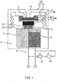
- FIG. 1 is a schematic diagram showing a cross-sectional structure of a galvanic cell type oxygen sensor according to the present embodiment.
- numeral 1 denotes a first holder lid (inner lid)
- numeral 2 denotes an O-ring
- numeral 3 denotes a protective film for preventing adhesion of dirt and dust or adhesion of a water film to a membrane
- numeral 4A denotes the membrane
- numeral 4B denotes a catalytic electrode
- numeral 5 denotes a positive electrode current collector
- numeral 6 denotes a positive electrode lead wire
- numeral 7 denotes an electrolyte solution
- numeral 8 denotes a negative electrode
- numeral 9 denotes a holder
- numeral 10 denotes a second holder lid (outer lid)
- numeral 11 denotes a bore for the supply of the electrolyte solution
- numeral 12 denotes a bore for the lead wire
- numeral 13 denotes a positive electrode current collector holding section
- numeral 14 denotes a correction resistor
- numeral 15 denotes a temperature compensation therm
- the galvanic cell type oxygen sensor according to the present embodiment may be embodied so as to have the configuration as shown in FIG. 1 , for example, and it includes the holder 9 and the positive electrode 45, negative electrode 8, and electrolyte solution 7, which are contained in the holder 9.
- the holder 9 is configured so as to contain the positive electrode 45, the negative electrode 8, and the electrolyte solution 7 therein.
- the material of the holder 9 is not particularly limited as long as it does not cause problems such as corrosion by the electrolyte solution 7 to be described below, and ABS resin is preferably used.
- the positive electrode 45 is contained in the holder 9.
- the material of the positive electrode 45 is not particularly limited as long as a current is generated by electrochemical reduction of oxygen on the positive electrode, and a catalyst made of gold (Au), silver (Ag), platinum (Pt), titanium (Ti), or the like that is active for oxidation and reduction is preferably used.
- the electrolyte solution 7 is contained in the holder 9.
- the electrolyte solution 7 contains a chelating agent.
- the molar concentration of the chelating agent is 1.4 mol/L or higher.
- the galvanic cell type oxygen sensor can attain a high response speed and also an improved service life of the oxygen sensor.
- the response speed is increased owing to the chelate effect.
- the molar concentration of the chelating agent contained in the electrolyte solution 7 is 1.4 mol/L or higher, the service life of the oxygen sensor is improved.
- the chelating agent whose molar concentration can be set to 1.4 mol/L or higher is at least one of citric acid and citrates.
- the citric acid and citrates exhibit high degrees of solubility (see the numerical value in brackets on the right) in water (25°C) (citric acid [73 g/100 ml], trisodium citrate [71 g/100 ml], and tripotassium citrate [167 g/100 ml]). Accordingly, the molar concentration of the chelating agent can be made high.
- the chelating agent at least contains tripotassium citrate.
- the solubility of tripotassium citrate in water is very high. Accordingly, the molar concentration of the chelating agent can be made still higher.
- the upper limit of the molar concentration varies depending on the type of chelating agent, and is determined as a maximum number of moles of the chelating agent that can be dissolved in 1 L (liter) of a solution (water) at 25°C.
- the chelating agent is a mixed solution containing citric acid and tripotassium citrate
- the upper limit is 3.0 mol/L, and more preferably 2.3 mol/L.
- acetic acid, boric acid, phosphoric acid, ammonia, carbonic acid, and salts thereof which are not encompassed in the "chelating agent" in the present invention, are not preferable, because they exhibit low complexing power and thus a high response speed cannot be attained when any of these substances alone is contained in the electrolyte solution 7 as the chelating agent.
- the electrolyte solution contains a chelating agent in the present invention means “the molar concentration of the chelating agent is 1.4 mol/L or higher” (providing an electrochemical oxygen sensor that attains a high response speed and also an improved service life of the oxygen sensor; the same applies hereinafter).
- the electrolyte solution 7 may contain, in addition to the chelating agent, any component(s) (including substances with low complexing power, such as acetic acid, boric acid, phosphoric acid, ammonia, carbonic acid, and salts thereof) other than the chelating agent.
- the pH of the electrolyte solution at 25°C (the same applies hereinafter) when the chelating agent is at least one of citric acid and citrates is not less than 2.09 and not more than 7.40.
- the electrolyte solution with a pH in the above-described range can be obtained by mixing citric acid and tripotassium citrate and adjusting the composition ratio thereof.
- the pH of the electrolyte solution may be adjusted by adding sodium hydroxide (NaOH), potassium hydroxide (KOH), or the like to a mixed solution containing citric acid and tripotassium citrate.
- the pH of the electrolyte solution also may be adjusted by adding an acid (e.g., acetic acid, phosphoric acid, or carbonic acid) to tripotassium citrate (pH 7.8 to 8.6).
- the pH is not less than 2.59 and not more than 6.90.
- the pH of the electrolyte solution at 25°C when the chelating agent is citric acid is preferably not less than 5.40 and not more than 7.40.
- the electrolyte solution with a pH in the above-described range can be obtained by mixing citric acid and tripotassium citrate and adjusting the composition ratio thereof.
- the pH of the electrolyte solution may be adjusted by adding sodium hydroxide (NaOH), potassium hydroxide (KOH), or the like to citric acid or/and tripotassium citrate.
- the pH of the electrolyte solution also may be adjusted by adding an acid (e.g., acetic acid, phosphoric acid, or carbonic acid) to tripotassium citrate (pH 7.8 to 8.6).
- the pH is not less than 5.90 and not more than 6.90.
- the pH of the electrolyte solution at 25°C when the chelating agent is citric acid is preferably not less than 3.75 and not more than 5.75.
- the electrolyte solution with a pH in the above-described range can be obtained by mixing citric acid and tripotassium citrate and adjusting the composition ratio thereof.
- the pH of the electrolyte solution may be adjusted by adding sodium hydroxide (NaOH), potassium hydroxide (KOH), an acid (e.g., acetic acid, phosphoric acid, or carbonic acid), or the like to a mixed solution containing citric acid and tripotassium citrate.
- the pH is not less than 4.25 and not more than 5.25.
- the pH of the electrolyte solution at 25°C when the chelating agent is citric acid is preferably not less than 2.09 and not more than 4.09.
- the electrolyte solution with a pH in the above-described range can be obtained by mixing citric acid and tripotassium citrate and adjusting the composition ratio thereof.
- the pH of the electrolyte solution may be adjusted by adding sodium hydroxide (NaOH), potassium hydroxide (KOH), an acid (e.g., acetic acid, phosphoric acid, or carbonic acid), or the like to a mixed solution containing citric acid and tripotassium citrate.
- the pH is not less than 2.59 and not more than 3.59.
- the negative electrode 8 is contained in the holder 9.
- the material of the negative electrode 8 is Sn or a Sn alloy.
- the material of the negative electrode 8 may also contain a metal(s) other than the negative electrode metals and other impurities.
- a metal(s) other than the negative electrode metals and other impurities include In, Au, Bi, Na, S, Se, and Ca.
- the negative electrode 8 is made of an Sn alloy.
- the Sn alloy is an Sn-Sb alloy.
- the metal structure of Sn is more microscopic than those in other Sn alloys, and therefore, transformation (phase transition) to ⁇ -Sn (also known as "tin pest") can be suppressed. Accordingly, it is considered that the use of the Sn-Sb alloy allows the sensor to operate at low temperature (e.g., 0°C) and that a decrease in the output stability of the sensor can be suppressed even at low temperature.
- the negative electrode 8 (preferably an Sn alloy and more preferably an Sn-Sb alloy) is substantially lead free.
- substantially lead free means that the content of Pb in the negative electrode 8 is less than 1000 ppm.
- the content of Sb in the Sn-Sb alloy is not particularly limited without departing from the gist of the present invention.
- the content of Sb in the Sn-Sb alloy is expressed in mass%, and is determined by performing EDX analysis (beam diameter: 1 mm) with respect to any desired portion of the negative electrode 8 to be subjected to measurement and calculating the content of Sb in all the metal elements measured in that portion.
- the galvanic cell type oxygen sensor include, as shown in FIG. 1 , the holder 9, the positive electrode 45, negative electrode 8, and electrolyte solution 7, which are contained in the holder 9, the membrane 4A provided on the positive electrode 45, the protective film 3 provided on the membrane 4A, the first holder lid (inner lid) 1 for fixing the protective film 3, the O-ring 2 disposed between the holder 9 and the inner lid 1, the second holder lid (outer lid) 10 for fixing the inner lid 1, and the correction resistor 14 and the temperature compensation thermistor 15, which are connected in series to the positive electrode 45 and the negative electrode 8.
- the holder lid 101 constituted by the outer lid 10 and the inner lid 1 is provided with a through hole 16 that serves as an oxygen supply pathway (space) leading to the protective film 3.
- the holder 9 is provided with an opening in an upper part thereof, and an outer peripheral portion of the opening is provided with a thread section that is formed of thread ridges and thread grooves and is used for threaded engagement with the outer lid 10.
- the positive electrode 45 is constituted by the catalytic electrode 4B for electrochemically reducing oxygen and the positive electrode current collector 5 disposed on the electrolyte solution 7 side of the catalytic electrode 4B.
- the material of the catalytic electrode 4B gold (Au), silver (Ag), platinum (Pt), or the like is typically used.
- titanium (Ti) is typically used. It is to be noted that both the materials are not limited to those described above.
- the positive electrode current collector holding section 13 for holding the positive electrode current collector 5 is disposed below the positive electrode current collector 5.
- This positive electrode current collector holding section 13 is provided with the bore 11 for the supply of the electrolyte solution to the positive electrode 45 and the bore 12 configured to allow the positive electrode lead wire 6 to pass therethrough.
- the material of the positive electrode current collector holding section 13 is not particularly limited, and ABS resin is typically used.
- the membrane 4A in the present embodiment is disposed for control of the entry of oxygen so as not to allow an excess amount of oxygen to reach the catalytic electrode 4B.
- the membrane 4A is such that it selectively allows oxygen to pass therethrough and also can limit the amount of oxygen passing therethrough.
- the material and the thickness of the membrane 4A are not particularly limited, and a fluorocarbon polymer such as polytetrafluoroethylene or a tetrafluoroetylene-hexafluoropropylene copolymer, a polyolefin such as polyethylene, or the like is typically used.
- the membrane 4A include porous membranes, non-porous membranes, and further, membranes in which capillary tubes are formed, which are called capillary-type membranes.
- the protective film 3 in the present embodiment is a porous resin film provided on the membrane 4A and has a function of preventing adhesion of dirt and dust or adhesion of a water film to the membrane 4A.
- the material of the protective film 3 is not particularly limited, and a fluorocarbon polymer such as polytetrafluoroethylene is typically used.
- the inner lid 1 in the present embodiment functions as a presser end plate for pressing the protective film 3 and the positive electrode 45.
- the outer lid 10 is screwed onto the holder 9, the inner lid 1 is pressed against the holder 9 via the O-ring 2, whereby the protective film 3 and the positive electrode 45 can be fixed to the holder 9 with maintaining airtightness and liquid tightness.
- the material of the inner lid 1 is not particularly limited, and ABS resin, polypropylene, polycarbonate, a fluorocarbon polymer, or the like is typically used.
- the O-ring 2 in the present embodiment is disposed between the holder 9 and the inner lid 1.
- the O-ring 2 is pressed and deformed, thereby allowing the airtightness and the liquid tightness to be maintained.
- the material of the O-ring 2 is not particularly limited, and nitrile rubber, silicone rubber, ethylene-propylene rubber, a fluorocarbon polymer, or the like is typically used.
- the outer lid 10 in the present embodiment is configured so as to seal the opening of the holder 9 in cooperation with the O-ring 2 and the inner lid 1.
- An inner peripheral portion of the outer lid 10 is provided with a thread section that is threadedly engageable with the thread section provided in the outer peripheral portion of the opening of the holder 9.
- the material of the outer lid 1 is not particularly limited, and ABS resin, polypropylene, polycarbonate, a fluorocarbon polymer, or the like is typically used.
- constituent elements denoted by numerals 1 to 15 in FIG. 1 are not limited those shown in FIG. 1 , and various changes and modifications in design may be made as long as functions as the oxygen sensor and the above-described oxygen supply pathways are provided.
- the present invention has been described using a galvanic cell type oxygen sensor in the present embodiment, the present invention is also applicable to a potentiostatic type oxygen sensor.
- the potentiostatic type oxygen sensor is a sensor configured such that a constant voltage is applied between a positive electrode and a negative electrode, and the voltage to be applied is set depending on the electrochemical characteristics of the respective electrodes and the type of gas to be detected.
- a current that flows between the positive electrode and the negative electrode when an appropriate constant voltage is applied therebetween is proportional to the oxygen gas concentration.
- the present invention is also applicable to a galvanic cell type dissolved oxygen sensor.
- FIG. 2 is a schematic diagram showing a cross-sectional structure of a galvanic cell type dissolved oxygen sensor which does not form part of the invention.
- the galvanic cell type dissolved oxygen sensor according Fig. 2 which does not form part of the invention, includes a membrane 21, a positive electrode 22, an electrolyte solution 23, a negative electrode 24, a lead wire 25, a correction resistor 26, and a temperature compensation thermistor 27.
- the membrane 21 is, for example, a membrane formed of a tetrafluoroetylene-hexafluoropropylene copolymer.
- the positive electrode 22 is, for example, a carbon fiber electrode coated with gold, and the gold acts as a catalyst effective for electrochemical reduction of oxygen.
- the electrolyte solution 23 is, for example, a mixed aqueous solution containing acetic acid, potassium acetate, and lead acetate.
- the negative electrode 24 is a lead electrode, for example.
- the lead wire 25 is made of titanium, for example.
- the temperature compensation thermistor 27 is attached to the outer wall of the galvanic cell type dissolved oxygen sensor.
- Galvanic cell type oxygen sensors shown in FIG. 1 were produced.
- the inner lid 1 was made of ABS resin
- the protective film 3 was a porous polytetrafluoroethylene sheet
- the membrane 4A was a tetrafluoroetylene-hexafluoropropylene copolymer membrane
- the catalytic electrode 4B was made of gold (Au)
- the positive electrode current collector 5 was made of titanium
- the positive electrode lead wire 6 was made of titanium
- the positive electrode current collector 5 and the positive electrode lead wire 6 were integrated with each other by welding.
- the negative electrode 8 was made of an Sn-5.0 Sb alloy (the numerical value on the left indicates the content of Sb in mass% in the Sn alloy).
- the holder body 9 was made of ABS resin.
- the outer lid 10 was made of ABS resin. The holder body 9 and the outer lid 10 were both threaded.
- the inner lid 1, the O-ring 2, the polytetrafluoroethylene sheet (protective film) 3, the membrane 4A formed of the tetrafluoroetylene-hexafluoropropylene copolymer membrane, the catalytic electrode 4B, and the positive electrode current collector 5 were pressed against each other when the outer lid 10 was screwed onto the holder body 9, whereby they were kept in a favorable contact state.
- the inner lid 1 functioned as a presser end plate, and the airtightness and the liquid tightness were secured by the O-ring 2.
- the numeral 11 denotes a bore for the supply of the electrolyte solution to the positive electrode and the membrane
- the numeral 12 denotes a perforation configured to allow the titanium lead wire of the positive electrode current collector to pass therethrough.
- a 1-year service life galvanic cell type oxygen sensor shown in FIG. 1 and having the same configuration as that of Example 1 except for the followings was produced: a tetrasodium EDTA (Etylene Diamine Tetraacetic Acid) aqueous solution (the solubility in water at 25°C was 60 g/100 ml) was used as the chelating agent and the molar concentration of the chelating agent was such that the solubility in water was close to the saturated concentration (the molar concentration: 1.2 mol/L).
- a tetrasodium EDTA Etylene Diamine Tetraacetic Acid
- the produced multiple galvanic cell type oxygen sensors were allowed to stand at ordinary temperature (25°C) for 360 days under the same environment, and thereafter, whether the output voltage of each of the oxygen sensors was stable was evaluated.
- the expression that the output voltage was stable as used in this context means that, when the trend of the output voltage over the measurement time is plotted with the horizontal axis representing the measurement time and the vertical axis representing the output voltage as shown in FIG. 3 , a straight line as shown in FIG. 3 is obtained.
- accelerated life testing was performed by passing oxygen gas at a concentration of 100% through each of the oxygen sensors at 40°C. Electrochemical reactions at 40°C proceed about twice as fast as those at room temperature, and also, electrochemical reactions when oxygen gas at a concentration of 100% is passed through the oxygen sensor proceed about 5 times as fast as those in the air. Accordingly, this accelerated life testing can determine the service lives of the oxygen sensors about 10 times faster than in the case where they are allowed to stand at room temperature in the air. In the accelerated life testing, the service lives of the oxygen sensors of the respective examples were evaluated by indicating how many times greater their service lives were than the service life of the oxygen sensor of Comparative Example 1, assuming that the service life of the oxygen sensor of Comparative Example 1 was 1.0. The results thereof are shown in Table 1.
- the galvanic cell type oxygen sensors of Examples 1 to 3 each exhibited a high response speed and a stable output voltage. Moreover, regarding the service life, it was found that the service life of the oxygen sensor of Example 3 was improved to 1.6 times that of the oxygen sensor of Comparative Example 1, and besides, the service lives of the oxygen sensors of Examples 1 and 2 were improved to about 3.0 times that of the oxygen sensor of Comparative Example 1.
Landscapes
- Chemical & Material Sciences (AREA)
- Life Sciences & Earth Sciences (AREA)
- Health & Medical Sciences (AREA)
- Physics & Mathematics (AREA)
- Chemical Kinetics & Catalysis (AREA)
- Electrochemistry (AREA)
- Molecular Biology (AREA)
- Analytical Chemistry (AREA)
- Biochemistry (AREA)
- General Health & Medical Sciences (AREA)
- General Physics & Mathematics (AREA)
- Immunology (AREA)
- Pathology (AREA)
- Measuring Oxygen Concentration In Cells (AREA)
- Electrolytic Production Of Non-Metals, Compounds, Apparatuses Therefor (AREA)
Applications Claiming Priority (2)
| Application Number | Priority Date | Filing Date | Title |
|---|---|---|---|
| JP2016256733A JP6537491B2 (ja) | 2016-12-28 | 2016-12-28 | 電気化学式酸素センサ |
| PCT/JP2017/046622 WO2018124066A1 (ja) | 2016-12-28 | 2017-12-26 | 電気化学式酸素センサ |
Publications (3)
| Publication Number | Publication Date |
|---|---|
| EP3495810A1 EP3495810A1 (en) | 2019-06-12 |
| EP3495810A4 EP3495810A4 (en) | 2019-08-21 |
| EP3495810B1 true EP3495810B1 (en) | 2020-11-04 |
Family
ID=62707440
Family Applications (1)
| Application Number | Title | Priority Date | Filing Date |
|---|---|---|---|
| EP17886846.9A Active EP3495810B1 (en) | 2016-12-28 | 2017-12-26 | Electrochemical oxygen sensor |
Country Status (5)
| Country | Link |
|---|---|
| US (2) | US20190219535A1 (enExample) |
| EP (1) | EP3495810B1 (enExample) |
| JP (1) | JP6537491B2 (enExample) |
| CN (1) | CN109642887B (enExample) |
| WO (1) | WO2018124066A1 (enExample) |
Families Citing this family (6)
| Publication number | Priority date | Publication date | Assignee | Title |
|---|---|---|---|---|
| CN117929502A (zh) * | 2018-10-17 | 2024-04-26 | 麦克赛尔株式会社 | 电化学氧传感器 |
| EP3882617B1 (en) * | 2020-01-21 | 2024-02-21 | Maxell, Ltd. | Electrochemical oxygen sensor |
| US20240003843A1 (en) * | 2020-11-25 | 2024-01-04 | Maxell, Ltd. | Electrochemical oxygen sensor and method for manufacturing the same |
| JP7539337B2 (ja) * | 2021-04-09 | 2024-08-23 | マクセル株式会社 | 電気化学式酸素センサ |
| US20220326174A1 (en) * | 2021-04-09 | 2022-10-13 | Maxell, Ltd. | Electrochemical oxygen sensor |
| CN113295755B (zh) * | 2021-05-18 | 2022-11-29 | 中国科学院合肥物质科学研究院 | 一种采样式快速原电池氧气传感器 |
Family Cites Families (13)
| Publication number | Priority date | Publication date | Assignee | Title |
|---|---|---|---|---|
| JPS52127392A (en) * | 1976-04-19 | 1977-10-25 | Hokushin Electric Works | Membrane type gas densitometer |
| DE3729287A1 (de) * | 1987-09-02 | 1989-03-23 | Draegerwerk Ag | Elektrochemische messzelle mit einem sauren elektrolyten |
| JPH06138080A (ja) * | 1992-03-12 | 1994-05-20 | Matsushita Electric Ind Co Ltd | バイオセンサ |
| JP2004132915A (ja) * | 2002-10-15 | 2004-04-30 | Oji Keisoku Kiki Kk | 微生物電極、微生物電極用酸素電極及びそれを用いる測定装置 |
| JP4062447B2 (ja) * | 2005-01-13 | 2008-03-19 | 株式会社ジーエス・ユアサコーポレーション | 定電位式酸素センサ |
| DE102006024022B4 (de) * | 2006-05-23 | 2008-05-08 | It Dr. Gambert Gmbh | Bleifreier galvanischer Sauerstoffsensor |
| WO2009069749A1 (ja) * | 2007-11-28 | 2009-06-04 | Gs Yuasa Corporation | 電気化学式酸素センサ |
| JP5145916B2 (ja) * | 2007-12-18 | 2013-02-20 | 東亜ディーケーケー株式会社 | ポーラログラフ式隔膜型電極用電解液およびポーラログラフ式隔膜型電極 |
| CN104094106B (zh) * | 2011-09-14 | 2016-11-09 | 生命安全销售股份公司 | 无铅电化学原电池型氧传感器 |
| CN102353711B (zh) * | 2011-10-18 | 2013-09-25 | 郑州炜盛电子科技有限公司 | 原电池型半固态溶解氧传感器 |
| DE102013011773B4 (de) * | 2013-07-15 | 2016-08-04 | It Dr. Gambert Gmbh | Galvanischer Sauerstoffsensor für die Messung in Gasgemischen |
| JP6004040B2 (ja) * | 2014-05-26 | 2016-10-05 | 株式会社Gsユアサ | ガルバニ電池式酸素センサ |
| CN104155355A (zh) * | 2014-08-20 | 2014-11-19 | 黄崇艺 | 氧传感器 |
-
2016
- 2016-12-28 JP JP2016256733A patent/JP6537491B2/ja active Active
-
2017
- 2017-12-26 US US16/331,178 patent/US20190219535A1/en not_active Abandoned
- 2017-12-26 CN CN201780049732.1A patent/CN109642887B/zh active Active
- 2017-12-26 EP EP17886846.9A patent/EP3495810B1/en active Active
- 2017-12-26 WO PCT/JP2017/046622 patent/WO2018124066A1/ja not_active Ceased
-
2024
- 2024-05-28 US US18/675,372 patent/US20240319133A1/en active Pending
Non-Patent Citations (1)
| Title |
|---|
| None * |
Also Published As
| Publication number | Publication date |
|---|---|
| WO2018124066A1 (ja) | 2018-07-05 |
| EP3495810A4 (en) | 2019-08-21 |
| CN109642887B (zh) | 2021-08-27 |
| JP2018109549A (ja) | 2018-07-12 |
| US20240319133A1 (en) | 2024-09-26 |
| EP3495810A1 (en) | 2019-06-12 |
| JP6537491B2 (ja) | 2019-07-03 |
| CN109642887A (zh) | 2019-04-16 |
| US20190219535A1 (en) | 2019-07-18 |
Similar Documents
| Publication | Publication Date | Title |
|---|---|---|
| US20240319133A1 (en) | Electrochemical oxygen sensor | |
| EP2219024B1 (en) | Electrochemical oxygen sensor | |
| US11733200B2 (en) | Electrochemical oxygen sensor | |
| US9146208B2 (en) | Lead-free oxygen sensor | |
| JP7610477B2 (ja) | 電気化学式酸素センサ | |
| EP1593962A1 (en) | Electrochemical oxygen sensor | |
| JP2019066328A (ja) | 電気化学式酸素センサ | |
| JP6707431B2 (ja) | ガルバニ電池式酸素センサ | |
| JP6899751B2 (ja) | 電気化学式酸素センサ | |
| EP3882617B1 (en) | Electrochemical oxygen sensor | |
| JP2018059719A (ja) | 電気化学式酸素センサ | |
| WO2023162960A1 (ja) | 電気化学式酸素センサおよびその製造方法 | |
| JP7539337B2 (ja) | 電気化学式酸素センサ | |
| EP3832297B1 (en) | Electrochemical oxygen sensor | |
| JPH0239740B2 (enExample) | ||
| JP2002310974A (ja) | 酸性気体の検出器 | |
| JP3650919B2 (ja) | 電気化学センサ | |
| US20220326174A1 (en) | Electrochemical oxygen sensor | |
| JP7555426B2 (ja) | 電気化学式酸素センサおよびその製造方法 |
Legal Events
| Date | Code | Title | Description |
|---|---|---|---|
| STAA | Information on the status of an ep patent application or granted ep patent |
Free format text: STATUS: THE INTERNATIONAL PUBLICATION HAS BEEN MADE |
|
| PUAI | Public reference made under article 153(3) epc to a published international application that has entered the european phase |
Free format text: ORIGINAL CODE: 0009012 |
|
| STAA | Information on the status of an ep patent application or granted ep patent |
Free format text: STATUS: REQUEST FOR EXAMINATION WAS MADE |
|
| 17P | Request for examination filed |
Effective date: 20190307 |
|
| AK | Designated contracting states |
Kind code of ref document: A1 Designated state(s): AL AT BE BG CH CY CZ DE DK EE ES FI FR GB GR HR HU IE IS IT LI LT LU LV MC MK MT NL NO PL PT RO RS SE SI SK SM TR |
|
| AX | Request for extension of the european patent |
Extension state: BA ME |
|
| STAA | Information on the status of an ep patent application or granted ep patent |
Free format text: STATUS: EXAMINATION IS IN PROGRESS |
|
| A4 | Supplementary search report drawn up and despatched |
Effective date: 20190722 |
|
| RIC1 | Information provided on ipc code assigned before grant |
Ipc: G01N 27/404 20060101AFI20190716BHEP Ipc: G01N 27/416 20060101ALI20190716BHEP |
|
| 17Q | First examination report despatched |
Effective date: 20190809 |
|
| DAV | Request for validation of the european patent (deleted) | ||
| DAX | Request for extension of the european patent (deleted) | ||
| GRAP | Despatch of communication of intention to grant a patent |
Free format text: ORIGINAL CODE: EPIDOSNIGR1 |
|
| STAA | Information on the status of an ep patent application or granted ep patent |
Free format text: STATUS: GRANT OF PATENT IS INTENDED |
|
| INTG | Intention to grant announced |
Effective date: 20200528 |
|
| GRAS | Grant fee paid |
Free format text: ORIGINAL CODE: EPIDOSNIGR3 |
|
| GRAA | (expected) grant |
Free format text: ORIGINAL CODE: 0009210 |
|
| STAA | Information on the status of an ep patent application or granted ep patent |
Free format text: STATUS: THE PATENT HAS BEEN GRANTED |
|
| REG | Reference to a national code |
Ref country code: DE Ref legal event code: R083 Ref document number: 602017027172 Country of ref document: DE |
|
| AK | Designated contracting states |
Kind code of ref document: B1 Designated state(s): AL AT BE BG CH CY CZ DE DK EE ES FI FR GB GR HR HU IE IS IT LI LT LU LV MC MK MT NL NO PL PT RO RS SE SI SK SM TR |
|
| REG | Reference to a national code |
Ref country code: GB Ref legal event code: FG4D |
|
| RIN2 | Information on inventor provided after grant (corrected) |
Inventor name: KITAZAWA, NAOHISA |
|
| REG | Reference to a national code |
Ref country code: CH Ref legal event code: EP |
|
| REG | Reference to a national code |
Ref country code: AT Ref legal event code: REF Ref document number: 1331477 Country of ref document: AT Kind code of ref document: T Effective date: 20201115 |
|
| REG | Reference to a national code |
Ref country code: IE Ref legal event code: FG4D |
|
| REG | Reference to a national code |
Ref country code: DE Ref legal event code: R096 Ref document number: 602017027172 Country of ref document: DE |
|
| REG | Reference to a national code |
Ref country code: NL Ref legal event code: MP Effective date: 20201104 |
|
| REG | Reference to a national code |
Ref country code: AT Ref legal event code: MK05 Ref document number: 1331477 Country of ref document: AT Kind code of ref document: T Effective date: 20201104 |
|
| PG25 | Lapsed in a contracting state [announced via postgrant information from national office to epo] |
Ref country code: GR Free format text: LAPSE BECAUSE OF FAILURE TO SUBMIT A TRANSLATION OF THE DESCRIPTION OR TO PAY THE FEE WITHIN THE PRESCRIBED TIME-LIMIT Effective date: 20210205 Ref country code: NO Free format text: LAPSE BECAUSE OF FAILURE TO SUBMIT A TRANSLATION OF THE DESCRIPTION OR TO PAY THE FEE WITHIN THE PRESCRIBED TIME-LIMIT Effective date: 20210204 Ref country code: FI Free format text: LAPSE BECAUSE OF FAILURE TO SUBMIT A TRANSLATION OF THE DESCRIPTION OR TO PAY THE FEE WITHIN THE PRESCRIBED TIME-LIMIT Effective date: 20201104 Ref country code: RS Free format text: LAPSE BECAUSE OF FAILURE TO SUBMIT A TRANSLATION OF THE DESCRIPTION OR TO PAY THE FEE WITHIN THE PRESCRIBED TIME-LIMIT Effective date: 20201104 Ref country code: PT Free format text: LAPSE BECAUSE OF FAILURE TO SUBMIT A TRANSLATION OF THE DESCRIPTION OR TO PAY THE FEE WITHIN THE PRESCRIBED TIME-LIMIT Effective date: 20210304 |
|
| PG25 | Lapsed in a contracting state [announced via postgrant information from national office to epo] |
Ref country code: AT Free format text: LAPSE BECAUSE OF FAILURE TO SUBMIT A TRANSLATION OF THE DESCRIPTION OR TO PAY THE FEE WITHIN THE PRESCRIBED TIME-LIMIT Effective date: 20201104 Ref country code: ES Free format text: LAPSE BECAUSE OF FAILURE TO SUBMIT A TRANSLATION OF THE DESCRIPTION OR TO PAY THE FEE WITHIN THE PRESCRIBED TIME-LIMIT Effective date: 20201104 Ref country code: BG Free format text: LAPSE BECAUSE OF FAILURE TO SUBMIT A TRANSLATION OF THE DESCRIPTION OR TO PAY THE FEE WITHIN THE PRESCRIBED TIME-LIMIT Effective date: 20210204 Ref country code: IS Free format text: LAPSE BECAUSE OF FAILURE TO SUBMIT A TRANSLATION OF THE DESCRIPTION OR TO PAY THE FEE WITHIN THE PRESCRIBED TIME-LIMIT Effective date: 20210304 Ref country code: LV Free format text: LAPSE BECAUSE OF FAILURE TO SUBMIT A TRANSLATION OF THE DESCRIPTION OR TO PAY THE FEE WITHIN THE PRESCRIBED TIME-LIMIT Effective date: 20201104 Ref country code: PL Free format text: LAPSE BECAUSE OF FAILURE TO SUBMIT A TRANSLATION OF THE DESCRIPTION OR TO PAY THE FEE WITHIN THE PRESCRIBED TIME-LIMIT Effective date: 20201104 Ref country code: SE Free format text: LAPSE BECAUSE OF FAILURE TO SUBMIT A TRANSLATION OF THE DESCRIPTION OR TO PAY THE FEE WITHIN THE PRESCRIBED TIME-LIMIT Effective date: 20201104 |
|
| REG | Reference to a national code |
Ref country code: LT Ref legal event code: MG9D |
|
| PG25 | Lapsed in a contracting state [announced via postgrant information from national office to epo] |
Ref country code: HR Free format text: LAPSE BECAUSE OF FAILURE TO SUBMIT A TRANSLATION OF THE DESCRIPTION OR TO PAY THE FEE WITHIN THE PRESCRIBED TIME-LIMIT Effective date: 20201104 |
|
| PG25 | Lapsed in a contracting state [announced via postgrant information from national office to epo] |
Ref country code: SM Free format text: LAPSE BECAUSE OF FAILURE TO SUBMIT A TRANSLATION OF THE DESCRIPTION OR TO PAY THE FEE WITHIN THE PRESCRIBED TIME-LIMIT Effective date: 20201104 Ref country code: LT Free format text: LAPSE BECAUSE OF FAILURE TO SUBMIT A TRANSLATION OF THE DESCRIPTION OR TO PAY THE FEE WITHIN THE PRESCRIBED TIME-LIMIT Effective date: 20201104 Ref country code: CZ Free format text: LAPSE BECAUSE OF FAILURE TO SUBMIT A TRANSLATION OF THE DESCRIPTION OR TO PAY THE FEE WITHIN THE PRESCRIBED TIME-LIMIT Effective date: 20201104 Ref country code: EE Free format text: LAPSE BECAUSE OF FAILURE TO SUBMIT A TRANSLATION OF THE DESCRIPTION OR TO PAY THE FEE WITHIN THE PRESCRIBED TIME-LIMIT Effective date: 20201104 Ref country code: RO Free format text: LAPSE BECAUSE OF FAILURE TO SUBMIT A TRANSLATION OF THE DESCRIPTION OR TO PAY THE FEE WITHIN THE PRESCRIBED TIME-LIMIT Effective date: 20201104 Ref country code: SK Free format text: LAPSE BECAUSE OF FAILURE TO SUBMIT A TRANSLATION OF THE DESCRIPTION OR TO PAY THE FEE WITHIN THE PRESCRIBED TIME-LIMIT Effective date: 20201104 |
|
| REG | Reference to a national code |
Ref country code: CH Ref legal event code: PL |
|
| REG | Reference to a national code |
Ref country code: DE Ref legal event code: R097 Ref document number: 602017027172 Country of ref document: DE |
|
| PG25 | Lapsed in a contracting state [announced via postgrant information from national office to epo] |
Ref country code: MC Free format text: LAPSE BECAUSE OF FAILURE TO SUBMIT A TRANSLATION OF THE DESCRIPTION OR TO PAY THE FEE WITHIN THE PRESCRIBED TIME-LIMIT Effective date: 20201104 Ref country code: DK Free format text: LAPSE BECAUSE OF FAILURE TO SUBMIT A TRANSLATION OF THE DESCRIPTION OR TO PAY THE FEE WITHIN THE PRESCRIBED TIME-LIMIT Effective date: 20201104 |
|
| REG | Reference to a national code |
Ref country code: BE Ref legal event code: MM Effective date: 20201231 |
|
| PLBE | No opposition filed within time limit |
Free format text: ORIGINAL CODE: 0009261 |
|
| STAA | Information on the status of an ep patent application or granted ep patent |
Free format text: STATUS: NO OPPOSITION FILED WITHIN TIME LIMIT |
|
| 26N | No opposition filed |
Effective date: 20210805 |
|
| PG25 | Lapsed in a contracting state [announced via postgrant information from national office to epo] |
Ref country code: NL Free format text: LAPSE BECAUSE OF FAILURE TO SUBMIT A TRANSLATION OF THE DESCRIPTION OR TO PAY THE FEE WITHIN THE PRESCRIBED TIME-LIMIT Effective date: 20201104 Ref country code: IE Free format text: LAPSE BECAUSE OF NON-PAYMENT OF DUE FEES Effective date: 20201226 Ref country code: AL Free format text: LAPSE BECAUSE OF FAILURE TO SUBMIT A TRANSLATION OF THE DESCRIPTION OR TO PAY THE FEE WITHIN THE PRESCRIBED TIME-LIMIT Effective date: 20201104 Ref country code: LU Free format text: LAPSE BECAUSE OF NON-PAYMENT OF DUE FEES Effective date: 20201226 |
|
| PG25 | Lapsed in a contracting state [announced via postgrant information from national office to epo] |
Ref country code: CH Free format text: LAPSE BECAUSE OF NON-PAYMENT OF DUE FEES Effective date: 20201231 Ref country code: SI Free format text: LAPSE BECAUSE OF FAILURE TO SUBMIT A TRANSLATION OF THE DESCRIPTION OR TO PAY THE FEE WITHIN THE PRESCRIBED TIME-LIMIT Effective date: 20201104 Ref country code: LI Free format text: LAPSE BECAUSE OF NON-PAYMENT OF DUE FEES Effective date: 20201231 |
|
| PG25 | Lapsed in a contracting state [announced via postgrant information from national office to epo] |
Ref country code: IS Free format text: LAPSE BECAUSE OF FAILURE TO SUBMIT A TRANSLATION OF THE DESCRIPTION OR TO PAY THE FEE WITHIN THE PRESCRIBED TIME-LIMIT Effective date: 20210304 Ref country code: TR Free format text: LAPSE BECAUSE OF FAILURE TO SUBMIT A TRANSLATION OF THE DESCRIPTION OR TO PAY THE FEE WITHIN THE PRESCRIBED TIME-LIMIT Effective date: 20201104 Ref country code: MT Free format text: LAPSE BECAUSE OF FAILURE TO SUBMIT A TRANSLATION OF THE DESCRIPTION OR TO PAY THE FEE WITHIN THE PRESCRIBED TIME-LIMIT Effective date: 20201104 Ref country code: CY Free format text: LAPSE BECAUSE OF FAILURE TO SUBMIT A TRANSLATION OF THE DESCRIPTION OR TO PAY THE FEE WITHIN THE PRESCRIBED TIME-LIMIT Effective date: 20201104 |
|
| PG25 | Lapsed in a contracting state [announced via postgrant information from national office to epo] |
Ref country code: MK Free format text: LAPSE BECAUSE OF FAILURE TO SUBMIT A TRANSLATION OF THE DESCRIPTION OR TO PAY THE FEE WITHIN THE PRESCRIBED TIME-LIMIT Effective date: 20201104 |
|
| PG25 | Lapsed in a contracting state [announced via postgrant information from national office to epo] |
Ref country code: BE Free format text: LAPSE BECAUSE OF NON-PAYMENT OF DUE FEES Effective date: 20201231 |
|
| REG | Reference to a national code |
Ref country code: GB Ref legal event code: 732E Free format text: REGISTERED BETWEEN 20220728 AND 20220803 |
|
| REG | Reference to a national code |
Ref country code: DE Ref legal event code: R081 Ref document number: 602017027172 Country of ref document: DE Owner name: MAXELL, LTD., OYAMAZAKI, JP Free format text: FORMER OWNER: MAXELL, LTD., KYOTO, JP |
|
| REG | Reference to a national code |
Ref country code: DE Ref legal event code: R081 Ref document number: 602017027172 Country of ref document: DE Owner name: MAXELL, LTD., OYAMAZAKI, JP Free format text: FORMER OWNER: MAXELL HOLDINGS, LTD., OYAMAZAKI, KYOTO, JP |
|
| PGFP | Annual fee paid to national office [announced via postgrant information from national office to epo] |
Ref country code: DE Payment date: 20241210 Year of fee payment: 8 |
|
| PGFP | Annual fee paid to national office [announced via postgrant information from national office to epo] |
Ref country code: GB Payment date: 20241226 Year of fee payment: 8 |
|
| PGFP | Annual fee paid to national office [announced via postgrant information from national office to epo] |
Ref country code: FR Payment date: 20241224 Year of fee payment: 8 |
|
| PGFP | Annual fee paid to national office [announced via postgrant information from national office to epo] |
Ref country code: IT Payment date: 20241227 Year of fee payment: 8 |