EP3495128A1 - Procédé de fabrication additive d'une lentille ophtalmique et lentille ophtalmique - Google Patents
Procédé de fabrication additive d'une lentille ophtalmique et lentille ophtalmique Download PDFInfo
- Publication number
- EP3495128A1 EP3495128A1 EP17306712.5A EP17306712A EP3495128A1 EP 3495128 A1 EP3495128 A1 EP 3495128A1 EP 17306712 A EP17306712 A EP 17306712A EP 3495128 A1 EP3495128 A1 EP 3495128A1
- Authority
- EP
- European Patent Office
- Prior art keywords
- optical element
- ophthalmic lens
- build support
- complementary
- complementary optical
- Prior art date
- Legal status (The legal status is an assumption and is not a legal conclusion. Google has not performed a legal analysis and makes no representation as to the accuracy of the status listed.)
- Withdrawn
Links
Images

Classifications
-
- B—PERFORMING OPERATIONS; TRANSPORTING
- B29—WORKING OF PLASTICS; WORKING OF SUBSTANCES IN A PLASTIC STATE IN GENERAL
- B29C—SHAPING OR JOINING OF PLASTICS; SHAPING OF MATERIAL IN A PLASTIC STATE, NOT OTHERWISE PROVIDED FOR; AFTER-TREATMENT OF THE SHAPED PRODUCTS, e.g. REPAIRING
- B29C64/00—Additive manufacturing, i.e. manufacturing of three-dimensional [3D] objects by additive deposition, additive agglomeration or additive layering, e.g. by 3D printing, stereolithography or selective laser sintering
- B29C64/10—Processes of additive manufacturing
- B29C64/106—Processes of additive manufacturing using only liquids or viscous materials, e.g. depositing a continuous bead of viscous material
- B29C64/112—Processes of additive manufacturing using only liquids or viscous materials, e.g. depositing a continuous bead of viscous material using individual droplets, e.g. from jetting heads
-
- B—PERFORMING OPERATIONS; TRANSPORTING
- B29—WORKING OF PLASTICS; WORKING OF SUBSTANCES IN A PLASTIC STATE IN GENERAL
- B29D—PRODUCING PARTICULAR ARTICLES FROM PLASTICS OR FROM SUBSTANCES IN A PLASTIC STATE
- B29D11/00—Producing optical elements, e.g. lenses or prisms
- B29D11/00009—Production of simple or compound lenses
- B29D11/00432—Auxiliary operations, e.g. machines for filling the moulds
-
- B—PERFORMING OPERATIONS; TRANSPORTING
- B29—WORKING OF PLASTICS; WORKING OF SUBSTANCES IN A PLASTIC STATE IN GENERAL
- B29C—SHAPING OR JOINING OF PLASTICS; SHAPING OF MATERIAL IN A PLASTIC STATE, NOT OTHERWISE PROVIDED FOR; AFTER-TREATMENT OF THE SHAPED PRODUCTS, e.g. REPAIRING
- B29C64/00—Additive manufacturing, i.e. manufacturing of three-dimensional [3D] objects by additive deposition, additive agglomeration or additive layering, e.g. by 3D printing, stereolithography or selective laser sintering
- B29C64/10—Processes of additive manufacturing
-
- B—PERFORMING OPERATIONS; TRANSPORTING
- B29—WORKING OF PLASTICS; WORKING OF SUBSTANCES IN A PLASTIC STATE IN GENERAL
- B29C—SHAPING OR JOINING OF PLASTICS; SHAPING OF MATERIAL IN A PLASTIC STATE, NOT OTHERWISE PROVIDED FOR; AFTER-TREATMENT OF THE SHAPED PRODUCTS, e.g. REPAIRING
- B29C64/00—Additive manufacturing, i.e. manufacturing of three-dimensional [3D] objects by additive deposition, additive agglomeration or additive layering, e.g. by 3D printing, stereolithography or selective laser sintering
- B29C64/40—Structures for supporting 3D objects during manufacture and intended to be sacrificed after completion thereof
-
- B—PERFORMING OPERATIONS; TRANSPORTING
- B29—WORKING OF PLASTICS; WORKING OF SUBSTANCES IN A PLASTIC STATE IN GENERAL
- B29C—SHAPING OR JOINING OF PLASTICS; SHAPING OF MATERIAL IN A PLASTIC STATE, NOT OTHERWISE PROVIDED FOR; AFTER-TREATMENT OF THE SHAPED PRODUCTS, e.g. REPAIRING
- B29C65/00—Joining or sealing of preformed parts, e.g. welding of plastics materials; Apparatus therefor
- B29C65/48—Joining or sealing of preformed parts, e.g. welding of plastics materials; Apparatus therefor using adhesives, i.e. using supplementary joining material; solvent bonding
-
- B—PERFORMING OPERATIONS; TRANSPORTING
- B29—WORKING OF PLASTICS; WORKING OF SUBSTANCES IN A PLASTIC STATE IN GENERAL
- B29D—PRODUCING PARTICULAR ARTICLES FROM PLASTICS OR FROM SUBSTANCES IN A PLASTIC STATE
- B29D11/00—Producing optical elements, e.g. lenses or prisms
- B29D11/00009—Production of simple or compound lenses
-
- B—PERFORMING OPERATIONS; TRANSPORTING
- B29—WORKING OF PLASTICS; WORKING OF SUBSTANCES IN A PLASTIC STATE IN GENERAL
- B29D—PRODUCING PARTICULAR ARTICLES FROM PLASTICS OR FROM SUBSTANCES IN A PLASTIC STATE
- B29D11/00—Producing optical elements, e.g. lenses or prisms
- B29D11/00663—Production of light guides
-
- B—PERFORMING OPERATIONS; TRANSPORTING
- B29—WORKING OF PLASTICS; WORKING OF SUBSTANCES IN A PLASTIC STATE IN GENERAL
- B29D—PRODUCING PARTICULAR ARTICLES FROM PLASTICS OR FROM SUBSTANCES IN A PLASTIC STATE
- B29D11/00—Producing optical elements, e.g. lenses or prisms
- B29D11/0074—Production of other optical elements not provided for in B29D11/00009- B29D11/0073
-
- B—PERFORMING OPERATIONS; TRANSPORTING
- B29—WORKING OF PLASTICS; WORKING OF SUBSTANCES IN A PLASTIC STATE IN GENERAL
- B29D—PRODUCING PARTICULAR ARTICLES FROM PLASTICS OR FROM SUBSTANCES IN A PLASTIC STATE
- B29D11/00—Producing optical elements, e.g. lenses or prisms
- B29D11/00865—Applying coatings; tinting; colouring
- B29D11/00894—Applying coatings; tinting; colouring colouring or tinting
- B29D11/00903—Applying coatings; tinting; colouring colouring or tinting on the surface
-
- B—PERFORMING OPERATIONS; TRANSPORTING
- B33—ADDITIVE MANUFACTURING TECHNOLOGY
- B33Y—ADDITIVE MANUFACTURING, i.e. MANUFACTURING OF THREE-DIMENSIONAL [3-D] OBJECTS BY ADDITIVE DEPOSITION, ADDITIVE AGGLOMERATION OR ADDITIVE LAYERING, e.g. BY 3-D PRINTING, STEREOLITHOGRAPHY OR SELECTIVE LASER SINTERING
- B33Y40/00—Auxiliary operations or equipment, e.g. for material handling
-
- B—PERFORMING OPERATIONS; TRANSPORTING
- B33—ADDITIVE MANUFACTURING TECHNOLOGY
- B33Y—ADDITIVE MANUFACTURING, i.e. MANUFACTURING OF THREE-DIMENSIONAL [3-D] OBJECTS BY ADDITIVE DEPOSITION, ADDITIVE AGGLOMERATION OR ADDITIVE LAYERING, e.g. BY 3-D PRINTING, STEREOLITHOGRAPHY OR SELECTIVE LASER SINTERING
- B33Y80/00—Products made by additive manufacturing
-
- B—PERFORMING OPERATIONS; TRANSPORTING
- B29—WORKING OF PLASTICS; WORKING OF SUBSTANCES IN A PLASTIC STATE IN GENERAL
- B29D—PRODUCING PARTICULAR ARTICLES FROM PLASTICS OR FROM SUBSTANCES IN A PLASTIC STATE
- B29D11/00—Producing optical elements, e.g. lenses or prisms
- B29D11/0073—Optical laminates
-
- B—PERFORMING OPERATIONS; TRANSPORTING
- B29—WORKING OF PLASTICS; WORKING OF SUBSTANCES IN A PLASTIC STATE IN GENERAL
- B29L—INDEXING SCHEME ASSOCIATED WITH SUBCLASS B29C, RELATING TO PARTICULAR ARTICLES
- B29L2011/00—Optical elements, e.g. lenses, prisms
- B29L2011/0016—Lenses
-
- B—PERFORMING OPERATIONS; TRANSPORTING
- B33—ADDITIVE MANUFACTURING TECHNOLOGY
- B33Y—ADDITIVE MANUFACTURING, i.e. MANUFACTURING OF THREE-DIMENSIONAL [3-D] OBJECTS BY ADDITIVE DEPOSITION, ADDITIVE AGGLOMERATION OR ADDITIVE LAYERING, e.g. BY 3-D PRINTING, STEREOLITHOGRAPHY OR SELECTIVE LASER SINTERING
- B33Y10/00—Processes of additive manufacturing
Definitions
- the invention relates to the field of the manufacture of ophthalmic lenses having at least one optical function.
- the invention concerns more specifically a method of manufacturing an ophthalmic lens.
- the invention further concerns an ophthalmic lens obtained at least partly by additive man ufacturing.
- Methods for manufacturing ophthalmic lenses with a complementary optical element obtained by additive manufacturing involve a step of obtaining the complementary optical element by depositing a plurality of predetermined volumes of material on a build support. Said complementary optical element is then transferred, with or without the build support, onto a starting optical system to form an ophthalmic lens.
- Added functions are for example a polarization or tinting filter, a hard-coat function, an anti-reflective function, a protective coat and a surface quality function.
- a problem that the invention aims to solve is thus to provide a method of manufacturing an ophthalmic lens by additive manufacturing wherein it is easier to provide added values to the ophthalmic lens.
- the invention provides method of manufacturing an ophthalmic lens having at least one optical function, comprising:
- Such a build support with at least one added value or adhesive has a combined action allowing to first provide a support for the additive manufacturing that may be integrated into the ophthalmic lens and then provide at least one added function to the ophthalmic lens.
- Using this build support allows to facilitate manufacturing of the ophthalmic lens because the addition of the added function is integrated to the additive manufacturing process rather than an additional step following thereof.
- the shape and the optical power of the complementary optical element are predetermined as a function of the desired optical function of the ophthalmic lens.
- the complementary optical element is assembled to a starting optical system with the build support remaining on the complementary optical element during the assembling step.
- the complementary optical element is assembled to the starting optical system so that the build support is disposed between the starting optical system and the complementary optical element.
- the build support is removed from the complementary optical element during or after the assembling step to obtain an ophthalmic lens free of build support.
- the method comprises a step of gluing in which a gluing element having adhesion properties is provided to or comprised in at least one among the complementary optical element, the starting optical system and the build support.
- the manufacturing method further comprises, before the assembling step, a step of adding the at least one added value or adhesive onto an external surface of the build support intended to receive the complementary optical element, said at least one added value or adhesive being configured to remain on the complementary optical element if the build support is removed from the complementary optical element.
- said at least one added function is provided after the assembling step.
- the build support is a film.
- the build support is configured to transfer said at least one added value or adhesive to the complementary optical element when the complementary optical element contacts the build support.
- the at least one added function is one among a polarization or tinting filter, a hard-coat function, an anti-reflective function, a protective coat and a surface quality function.
- the invention also provides an ophthalmic lens having at least one optical function, comprising:
- the invention further provides an ophthalmic lens having at least one optical function, the ophthalmic lens being obtained by the manufacturing method as described above, the ophthalmic lens comprising:
- the ophthalmic lens further comprises a starting optical system assembled to a surface of the complementary optical element.
- the build support is disposed between the complementary optical element and the starting optical system.
- Figure 1 schematically shows an ophthalmic lens obtained by the deposition of predetermined volumes on a build support.
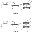
- Figure 2 to 4 each schematically shows various steps of an embodiment of a method of manufacturing an ophthalmic lens comprising a complementary optical element, a build support and a starting optical system.
- an ophthalmic lens 40 having at least one optical function is provided.
- a method of manufacturing such an ophthalmic lens 40 is also provided.
- the ophthalmic lens 40 comprises a build support 10 and a complementary optical element 12 providing at least a part of the optical function of the ophthalmic lens 40.
- the optical function of a lens, of a system or of an optical element means the optical response of this lens or of this system or of this element, namely a function that defines any modification in the propagation and transmission of an optical beam through the lens, the system or the optical element concerned, whatever the angle of incidence of the incident optical beam and whatever the geometric extent of an input diopter illuminated by the incident optical beam.
- Said at least one optical function may be simple or complex.
- the optical function is defined as the distribution of wearer power and astigmatism characteristics and of higher-order aberrations associated with the lens, with the system or with the optical element for all the directions of gaze of a wearer of this lens, of this system or of this element. That of course assumes that the geometric positioning of the lens, of the system or of the optical element with respect to the eye of the wearer has been predetermined.
- the complementary optical element 12 is obtained by a step of additively manufacturing the complementary optical element 12 by depositing a plurality of predetermined volume elements 14 on the build support 10.
- additive manufacturing it is meant a manufacturing technology as defined in the international standard ASTM 2792-12, which mentions a process of joining materials to make objects from 3D model data, usually layer upon layer, as opposed to subtractive manufacturing methodologies, such as traditional machining.
- the additive manufacturing method may be selected in, but is not limited to, the list consisting of stereolithography, mask stereolithography or mask projection stereolithography, polymer jetting, scanning laser sintering or SLS, scanning laser melting or SLM, fused deposition modeling or FDM.
- the complementary optical element 12 is formed by the plurality of predetermined volume elements 14 which are juxtaposed and superposed to form a plurality of superposed layers of a material. Dimensions of each of the superposed layers are chosen to fit a predetermined profile 16 of the complementary optical element 12 (dotted line).
- the layers each have a thickness that is constant over the length and all have the same thickness. The thickness of these layers is between 0,1 ⁇ m and 100 ⁇ m, preferably between 0,5 ⁇ m and 10 ⁇ m.
- the minimum thickness of the predetermined volume elements 14 mainly depends on the additive manufacturing method that is used to obtain the complementary optical element 30.
- the material of the complementary optical element 12 is compatible with additive manufacturing.
- the material is an acrylic polymer, more specifically a photopolymer, for example a photopolymer such as the product marketed by the company OBJET Ltd, under the trade name of VeroClear.
- additive manufacturing here corresponds to a three-dimensional printing or stereolithography method, or even to a method of fused filament fabrication.
- the additive manufacture is one among polymer jetting and stereolithography.
- the complementary optical element 12 has a curved, more specifically convex, front side and a planar back side.
- the front and back sides of the complementary optical element 12 may be each planar or curved.
- Shape of the complementary optical element 12, or predetermined profile 16, is determined depending on the desired optical function of the ophthalmic lens 40.
- “planar” does not necessarily mean “smooth” and does not necessarily exclude the presence of roughness.
- “planar” surface means that this surface has a curvature close to zero.
- the additive manufacture of the complementary optical element 12 may comprise, in addition to the deposition of the plurality of successive and superposed layers, one or more photopolymerization steps. It will also be noted, that the polymerization of the complementary optical element 12 may not be completely over at the end of the step of additive manufacture of this complementary optical element 12. In this later case, a final polymerization of the complementary optical element 12 may be totally completed during or after assembling step to adapt the shape of the complementary optical system 12 to a substrate on which it is then transferred.
- the build support 10 comprises at least one added value or adhesive configured to provide to the ophthalmic lens 40 at least one added function.
- This at least one added function is one among a polarization or tinting filter, a hard-coat function, an anti-reflective function, a protective coat and a surface quality function.
- Added values under the meaning of the invention are layers or elements that modify the mechanical or optical properties of the ophthalmic lens without influencing the optical power of said ophthalmic lens.
- a non exhaustive list of added values can be found hereafter : anti-scratch layers, also called hard-coats or abrasion resistant coatings, anti-shock layers, sometimes called primer layers or coatings, tinted layers or dyes, photochromic layers or dye, polarized layers, antistatic layers, anti-reflective layers or stacks, mirrors or partial mirror layers, filtering layers that selectively absorb or reflect one or more wavelength within the near Ultraviolet, the visible or near infra-red wavelength ranges, hydrophobic, hydrophilic or oleophobic layers, also known as anti-smudge or anti-fog layers, and also active layers comprising liquid crystals or other elements activated by an electric signal.
- the build support 10 may be configured to transfer said at least one added value or adhesive to the complementary optical element 12 when the complementary optical element 12 contacts the build support 10.
- the manufacturing method may comprise, before the assembling step, a step of adding the at least one added value or adhesive onto an external surface of the build support 10 intended to receive the complementary optical element 12.
- said at least one added value or adhesive is configured to remain on the complementary optical element 12 if the build support 10 is removed from the complementary optical element 12.
- the added value may be a specific surface quality provided by the internal side of the build support 10 to the complement optical element 12.
- said at least one added function may be provided after the assembling step.
- the adhesive is defined as being a layer configured to ease the adhesion of the complementary optical element 12 on the build support 10.
- the adhesive is configured to be used in a later step of the manufacturing method.
- the build support 10 may be a film.
- the build support 10 is a thin sheet or membrane. Forming the build support as a film allows the build support to be selectively shaped to ease manufacturing of the ophthalmic lens.
- the build support may be initially flat to facilitate additive manufacturing and to allow manufacturing of several complementary optical element on a single build support. Then, the build support formed as a film may be bent to have a curved shape corresponding to a surface on which the build support has to be disposed.
- the complementary optical element may be bent together with the build support to improve handling and positioning of the complementary optical element onto a substrate, as a starting optical system. Therefore, the build support as a film allows to optimize and facilitate the manufacturing method from the manufacturing of the complementary optical element to a potential transfer of the complementary optical element onto a substrate.
- the build support 10 is preferably flexible. In this way, the build support 10 may be selectively shaped. Particularly, the flexibility of the build support 10 makes it possible to shape or bend the complementary optical element 40 together with the build support 10 so that handling of the complementary optical element 40 is facilitated.
- This step of shaping or bending may be a thermoforming step when the build support 10 is a thermoset material.
- the curved shape of the complementary optical element 12 may be a final or intermediate shape. Alternatively, the film may be rigid.
- the build support 10 may be in the form of a patch. It will be noted that a patch differs from a film in that the patch has a mechanical behavior allowing the build support 10 to support its own weight so as to remain in a predetermined position or shape. Preferably, the patch has a predetermined flexibility allowing the build support 10 to be easily shaped or bent under a predetermined stress.
- the build support 10 comprises a body provided with a build surface 15 which in this instance is of planar overall shape.
- the build support 10 may be curved or bent before the step of additive manufacturing to obtain a complementary optical element 12 in a final shape, for example a shape close to the curvature of a substrate on which the complementary optical element 12 is intended to be then disposed.
- the build support 10 is preferably made of Cellulose Triacetate (TAC) or polycarbonate or Polyethylene terephthalate (PET).
- TAC Cellulose Triacetate
- PET Polyethylene terephthalate
- the thickness of the build support 10 is preferably between 50 ⁇ m and 500 ⁇ m, most preferably between 100 ⁇ m and 300 ⁇ m.
- the build support 10 may be configured to be used with a plurality of complementary optical elements 12 successively manufactured on the build support 10.
- a plurality of complementary optical elements 12 intended to be part of different ophthalmic lenses 40 may be additively manufactured on a single build support 10.
- Said plurality of complementary optical elements 12 may be then separated with an additional step of cutting the build support 10 between each of the complementary optical elements 12.
- additive manufacturing of complementary optical elements 12 may be automated.
- the build support 10 is in the form of a roll which is rolled out to receive the additively manufactured complementary optical elements 12.
- the build support 10 is part of the ophthalmic lens 40. In other words, the build support 10 remains in contact with the complementary optical element 12 to form the ophthalmic lens 40.
- the build support 10 may be disposed either on a first surface of the complementary optical element 12 intended to face an eye of a user when the ophthalmic lens 40 is mounted on a frame worn by the user or on a second surface opposite to the first surface.
- the ophthalmic lens 40 may further comprises a starting optical system 30 assembled to a surface of the complementary optical element 12.
- the starting optical system 30 may have an initial optical function. It will be noted that it is chiefly the complementary optical element 12 which confers the optical function on the ophthalmic lens 40, even if the starting optical system 30 already has a simple or complex optical function. In other words, without this complementary optical element 12, the ophthalmic lens 40 cannot exhibit the optical function prescribed for it.
- This complementary optical element 12 therefore has nothing to do with a simple surface coating, such as an antireflective coating, an antifog coating, a scratchproof coating or even a dirt-resistant coating.
- This starting optical system 30 is preferably made of a material generally used for the manufacture of ophthalmic lens, such as the allylic polymer known by the name CR39.
- the starting optical system 30 may also be made of polycarbonate or MR7 polymer.
- the starting optical system 30 may be manufactured by casting, injection, surfacing or by additive manufacturing.
- the starting optical system 30 is preferably a thin lens which power is around to the planned Rx. Particularly, the starting optical system 30 has a local thickness which is higher than 0.3 mm and preferably higher than 0.5 mm.
- the starting optical system 30 may be spherical, torical or progressive.
- the starting optical system has a planar front side and a curved back side. Depending on the desired optical function, the front and back sides of the starting optical system 30 may be each planar or curved.
- the complementary optical element 12 is transferred on a surface of the starting optical system 30, preferably using lamination processes. This transfer may be performed by a film applicator method, a pad printing method, a membrane applicator or a combination thereof.
- the build support 10 is maintained by its edge and the starting optical system 10 is pushed against the complementary optical element 12. This method may be performed under vacuum to complete the adhesion of the different layers.
- a deformable stamp presses the complementary optical element 12 together with the build support 10 onto the starting optical system 30.
- the stamp is preferably made of rubber.
- This pad printing method is preferably performed when the complementary optical element 12 has to be transferred on a concave surface.
- the membrane applicator method is very close to the pad printing method but differs from this latter method in that the rubber stamp is replaced by an inflated membrane.
- the shape and the optical power of the complementary optical element 12 are preferably predetermined as a function of the desired optical function of the ophthalmic lens 40.
- a geometric transfer law is used to determine the deformation characteristics of the complementary optical element 12 when it is transferred onto the starting optical system 30.
- Such a geometric transfer law is for example defined in the document US 2015/0241714 A1 .
- the build support 10 may be configured to transfer said at least one added value or adhesive to the complementary optical element 12 when the complementary optical element 12 contacts the build support 10.
- the manufacturing method may comprise, before the assembling step, a step of adding the at least one added value or adhesive onto an external surface of the build support 10 intended to receive the complementary optical element 12.
- said at least one added value or adhesive is configured to remain on the complementary optical element 12 if the build support 10 is removed from the complementary optical element 12.
- the added value may be a specific surface quality provided by the internal side of the build support 10 to the complement optical element 12.
- said at least one added function may be provided after the assembling step.
- the complementary optical element 12, with or without the build support 10, may be selectively assembled on the front side or on the back side of the starting optical system 30.
- the complementary optical element 12 may be selectively assembled on the surface of the starting optical system 30 which is intended to face the eye of the wearer or on the opposite surface.
- the build support 10 may be disposed on the first or second surface of the complementary optical element 12.
- the build support 10 may be part of the ophthalmic lens 40 or removed during or after the assembling step.
- the complementary optical element 12 is assembled to the starting optical system 30 with the build support 10 remaining on the complementary optical element 12 during an assembling step.
- the build support 10 may be disposed between the complementary optical element 12 and the starting optical system 30 or as an external layer of the ophthalmic lens 40.
- the complementary optical element 12 is assembled to the starting optical system 30 so that the build support 10 is disposed between the starting optical system 30 and the complementary optical element 12.
- the complementary optical element 12 is disposed between the build support 10 and the starting optical system 30.
- An optional step of edging the build support 10 may be performed to make the peripheral edge of the build support 10 correspond to the external edge of the complementary optical element 12 and the starting optical system 30.
- the build support 10 is removed from the complementary optical element 12 during or after the assembling step.
- the added value may be a function that eases removing the build support 10 from the complementary optical element 12, as a fluorized polymer. Removing the build support 10 from the complementary optical element 12 allows to get an improved optical quality of the external surface of the complementary optical element 12 without any smoothing additional step. The optical quality of the external surface of the complementary optical element 12 is thus provided by the build support 10.
- Figures 2-4 schematically show various steps of three embodiments of the method of manufacturing the ophthalmic lens 40.
- the complementary optical element 12 is additively manufactured on the build support 10.
- the complementary optical element 12 and the build support 10 are transferred onto the starting optical system 30 to form the ophthalmic lens 40.
- the build support 10 is part the ophthalmic lens 40 so that it remains in contact with the complementary optical element 12 after the transferring step.
- the build support 10 is disposed between the starting optical system 30 and the complementary optical element 12 in the embodiment of figure 2 whereas the build support 10 is disposed as an external layer of the ophthalmic lens 40 in the embodiment of figure 4 .
- An optional step of edging the build support 10 is then performed to make the peripheral edge of the build support 10 correspond to the external edge of the complementary optical element 12 and the starting optical system 30. Conversely, in the embodiment of figure 3 , the build support 10 is removed from complementary optical element 12 after transferring it onto the starting optical system 30.
- the manufacturing method comprises a step of gluing in which a gluing element or an adhesive having adhesion properties is provided to or comprised in at least one among the complementary optical element 12, the starting optical system 30 and the build support 10.
- this gluing element may be a gluing layer disposed between two layers of the ophthalmic lens 40.
- Polymer jetting technology is preferred to deposit the glue layer on a selected area. Most preferably, the same equipment is used for manufacturing the glue layer and the complementary optical element 12. Another advantage of polymer jetting technology is that additive manufacturing machine can have multiple printing heads with various materials.
- the glue layer may also be deposited by spin or spray coatings. Particularly, spin coating is preferred when deposited onto the starting optical system 30 and spray coating is preferred when deposited onto the build support 10. These spin and spray coatings are specifically interesting to deposit a pressure sensitive adhesive.
- the gluing element may be chosen to be activated with light, by thermal curing or by pression.
- At least one among the build support 10, the complementary optical element 12 and the starting optical system 30 is at least partially transparent to the activation wavelength.
- the curing temperature is preferably below the glass transition of the build support 10, the complementary optical element 12 and the starting optical system 30 to avoid lens distortion.
- Thermal activation is preferably used when thermal expansion of the build support 10, the complementary optical element 12 and the starting optical system 30 are close to each other.
- the gluing element is a pressure-sensitive adhesive (PSA) that is preferably at least one of the material of the build support 10.
- PSA pressure-sensitive adhesive
- the gluing element may be a polymer resin used for manufacturing the complementary optical element 12.
Priority Applications (8)
| Application Number | Priority Date | Filing Date | Title |
|---|---|---|---|
| EP17306712.5A EP3495128A1 (fr) | 2017-12-06 | 2017-12-06 | Procédé de fabrication additive d'une lentille ophtalmique et lentille ophtalmique |
| CN201880078863.7A CN111433009A (zh) | 2017-12-06 | 2018-12-05 | 增材制造眼科镜片的方法和眼科镜片 |
| US16/770,848 US11772322B2 (en) | 2017-12-06 | 2018-12-05 | Method of additively manufacturing an ophthalmic lens with at least one added function |
| EP18811051.4A EP3720692A1 (fr) | 2017-12-06 | 2018-12-05 | Méthode de fabrication additive d'une lentille ophtalmique et lentille ophtalmique |
| PCT/EP2018/083699 WO2019110692A1 (fr) | 2017-12-06 | 2018-12-05 | Méthode de fabrication additive d'une lentille ophtalmique et lentille ophtalmique |
| KR1020207016256A KR102424134B1 (ko) | 2017-12-06 | 2018-12-05 | 안과 렌즈의 부가 제조 방법 및 안과 렌즈 |
| JP2020530997A JP2021505953A (ja) | 2017-12-06 | 2018-12-05 | 眼用レンズの付加的な製造方法、及び眼用レンズ |
| JP2023150311A JP2023164574A (ja) | 2017-12-06 | 2023-09-15 | 眼用レンズの付加的な製造方法、及び眼用レンズ |
Applications Claiming Priority (1)
| Application Number | Priority Date | Filing Date | Title |
|---|---|---|---|
| EP17306712.5A EP3495128A1 (fr) | 2017-12-06 | 2017-12-06 | Procédé de fabrication additive d'une lentille ophtalmique et lentille ophtalmique |
Publications (1)
| Publication Number | Publication Date |
|---|---|
| EP3495128A1 true EP3495128A1 (fr) | 2019-06-12 |
Family
ID=60782118
Family Applications (2)
| Application Number | Title | Priority Date | Filing Date |
|---|---|---|---|
| EP17306712.5A Withdrawn EP3495128A1 (fr) | 2017-12-06 | 2017-12-06 | Procédé de fabrication additive d'une lentille ophtalmique et lentille ophtalmique |
| EP18811051.4A Pending EP3720692A1 (fr) | 2017-12-06 | 2018-12-05 | Méthode de fabrication additive d'une lentille ophtalmique et lentille ophtalmique |
Family Applications After (1)
| Application Number | Title | Priority Date | Filing Date |
|---|---|---|---|
| EP18811051.4A Pending EP3720692A1 (fr) | 2017-12-06 | 2018-12-05 | Méthode de fabrication additive d'une lentille ophtalmique et lentille ophtalmique |
Country Status (6)
| Country | Link |
|---|---|
| US (1) | US11772322B2 (fr) |
| EP (2) | EP3495128A1 (fr) |
| JP (2) | JP2021505953A (fr) |
| KR (1) | KR102424134B1 (fr) |
| CN (1) | CN111433009A (fr) |
| WO (1) | WO2019110692A1 (fr) |
Cited By (3)
| Publication number | Priority date | Publication date | Assignee | Title |
|---|---|---|---|---|
| EP3756872A1 (fr) * | 2019-06-24 | 2020-12-30 | Essilor International | Procédé de fabrication d'un article optique doté d'un film fonctionel |
| EP3888894A1 (fr) * | 2020-03-31 | 2021-10-06 | Essilor International | Plaquettes stratifiées contenant un film intérieur souple et déformable |
| EP3974163A1 (fr) * | 2020-09-28 | 2022-03-30 | Essilor International | Procédé d'impression d'un film thermoplastique sur un moule optique |
Citations (7)
| Publication number | Priority date | Publication date | Assignee | Title |
|---|---|---|---|---|
| US20060065989A1 (en) * | 2004-09-29 | 2006-03-30 | Thad Druffel | Lens forming systems and methods |
| US20090091825A1 (en) * | 2006-04-27 | 2009-04-09 | Seiko Epson Corporation | Plastic Polarized Lens |
| EP2878989A1 (fr) * | 2013-11-29 | 2015-06-03 | Carl Zeiss Vision International GmbH | Procédé de fabrication d'un verre de lunettes et verre de lunettes |
| US20150241714A1 (en) | 2012-09-28 | 2015-08-27 | Essilor International (Compagnie Generale D'optique) | Method for manufacturing an ophthalmic lens |
| US20160161761A1 (en) * | 2013-07-08 | 2016-06-09 | Essilor International (Compagnie Generale D'optique) | Method for manufacturing at least one ophthalmic lens |
| US20170165931A1 (en) * | 2014-06-30 | 2017-06-15 | Anteryon Wafer Optics B.V. | Method for manufacturing a lens structure |
| EP3311994A1 (fr) * | 2016-10-21 | 2018-04-25 | Carl Zeiss Vision International GmbH | Procédé, en particulier procédé d'impression 3d destiné à la fabrication d'un verre de lunette |
Family Cites Families (8)
| Publication number | Priority date | Publication date | Assignee | Title |
|---|---|---|---|---|
| CN1918252A (zh) * | 2004-02-06 | 2007-02-21 | 日东电工株式会社 | 涂布用涂料、使用该涂料的光学薄膜的制造方法、光学薄膜、偏振片及图像显示装置 |
| US8252369B2 (en) * | 2008-05-21 | 2012-08-28 | Essilor International (Compagnie Generale D'optique) | Process for applying a coating onto a fresnel lens forming surface |
| JP2012197390A (ja) | 2011-03-23 | 2012-10-18 | Toyo Ink Sc Holdings Co Ltd | 感圧式接着剤組成物、及びそれを用いてなる積層体 |
| FR3006622B1 (fr) * | 2013-06-07 | 2015-07-17 | Essilor Int | Procede de fabrication d'une lentille ophtalmique |
| US9969135B2 (en) * | 2013-07-31 | 2018-05-15 | Essilor International (Compagnie Generale D'optique) | Additive manufacturing for transparent ophthalmic lens |
| US9933632B2 (en) * | 2014-03-26 | 2018-04-03 | Indizen Optical Technologies, S.L. | Eyewear lens production by multi-layer additive techniques |
| CN204731504U (zh) * | 2015-05-04 | 2015-10-28 | 中青辰光(北京)科技有限公司 | 一种复合型偏光镜片 |
| FR3039659B1 (fr) * | 2015-07-28 | 2018-08-17 | Essilor International | Lentille ophtalmique et procede de fabrication associe |
-
2017
- 2017-12-06 EP EP17306712.5A patent/EP3495128A1/fr not_active Withdrawn
-
2018
- 2018-12-05 WO PCT/EP2018/083699 patent/WO2019110692A1/fr unknown
- 2018-12-05 EP EP18811051.4A patent/EP3720692A1/fr active Pending
- 2018-12-05 US US16/770,848 patent/US11772322B2/en active Active
- 2018-12-05 JP JP2020530997A patent/JP2021505953A/ja active Pending
- 2018-12-05 KR KR1020207016256A patent/KR102424134B1/ko active IP Right Grant
- 2018-12-05 CN CN201880078863.7A patent/CN111433009A/zh active Pending
-
2023
- 2023-09-15 JP JP2023150311A patent/JP2023164574A/ja active Pending
Patent Citations (7)
| Publication number | Priority date | Publication date | Assignee | Title |
|---|---|---|---|---|
| US20060065989A1 (en) * | 2004-09-29 | 2006-03-30 | Thad Druffel | Lens forming systems and methods |
| US20090091825A1 (en) * | 2006-04-27 | 2009-04-09 | Seiko Epson Corporation | Plastic Polarized Lens |
| US20150241714A1 (en) | 2012-09-28 | 2015-08-27 | Essilor International (Compagnie Generale D'optique) | Method for manufacturing an ophthalmic lens |
| US20160161761A1 (en) * | 2013-07-08 | 2016-06-09 | Essilor International (Compagnie Generale D'optique) | Method for manufacturing at least one ophthalmic lens |
| EP2878989A1 (fr) * | 2013-11-29 | 2015-06-03 | Carl Zeiss Vision International GmbH | Procédé de fabrication d'un verre de lunettes et verre de lunettes |
| US20170165931A1 (en) * | 2014-06-30 | 2017-06-15 | Anteryon Wafer Optics B.V. | Method for manufacturing a lens structure |
| EP3311994A1 (fr) * | 2016-10-21 | 2018-04-25 | Carl Zeiss Vision International GmbH | Procédé, en particulier procédé d'impression 3d destiné à la fabrication d'un verre de lunette |
Cited By (7)
| Publication number | Priority date | Publication date | Assignee | Title |
|---|---|---|---|---|
| EP3756872A1 (fr) * | 2019-06-24 | 2020-12-30 | Essilor International | Procédé de fabrication d'un article optique doté d'un film fonctionel |
| WO2020260291A1 (fr) * | 2019-06-24 | 2020-12-30 | Essilor International | Procédé de fabrication d'un article optique avec un film à valeur ajoutée |
| CN113993691A (zh) * | 2019-06-24 | 2022-01-28 | 依视路国际公司 | 用于制造具有附加值膜的光学制品的方法 |
| EP3888894A1 (fr) * | 2020-03-31 | 2021-10-06 | Essilor International | Plaquettes stratifiées contenant un film intérieur souple et déformable |
| WO2021198374A1 (fr) * | 2020-03-31 | 2021-10-07 | Essilor International | Plaquettes fonctionnelles par impression 3d |
| EP3974163A1 (fr) * | 2020-09-28 | 2022-03-30 | Essilor International | Procédé d'impression d'un film thermoplastique sur un moule optique |
| WO2022064028A1 (fr) * | 2020-09-28 | 2022-03-31 | Essilor International | Procédé d'impression d'un film thermoplastique sur un moule optique |
Also Published As
| Publication number | Publication date |
|---|---|
| JP2021505953A (ja) | 2021-02-18 |
| WO2019110692A1 (fr) | 2019-06-13 |
| EP3720692A1 (fr) | 2020-10-14 |
| JP2023164574A (ja) | 2023-11-10 |
| CN111433009A (zh) | 2020-07-17 |
| KR20200079309A (ko) | 2020-07-02 |
| KR102424134B1 (ko) | 2022-07-25 |
| US11772322B2 (en) | 2023-10-03 |
| US20200391434A1 (en) | 2020-12-17 |
Similar Documents
| Publication | Publication Date | Title |
|---|---|---|
| CN110031984B (zh) | 眼镜镜片及其生产方法 | |
| JP2019521397A5 (fr) | ||
| US10281738B2 (en) | Method for manufacturing an ophthalmic lens | |
| US11772322B2 (en) | Method of additively manufacturing an ophthalmic lens with at least one added function | |
| CN108474873A (zh) | 用于将全息光学元件与眼镜镜片整合在一起的系统、制品和方法 | |
| US6886937B2 (en) | Ophthalmic lens with graded interference coating | |
| CN112888991B (zh) | 具有限定封装微镜片的压花膜的光学制品及其制造方法 | |
| CA2304764A1 (fr) | Verre ophtalmique synthetise a partir de ses specifications | |
| JP2016500842A (ja) | 保護された微細構造を有する眼鏡レンズの作製 | |
| WO2013074269A1 (fr) | Verres en 3d et ses procédés de fabrication | |
| US10274749B2 (en) | Producing microstructured spectacle lenses by means of transfer layer | |
| JP4261344B2 (ja) | インサートを有するレンズを型で作る方法 | |
| CN110023066B (zh) | 用于制造眼科制品的方法 | |
| US11940673B2 (en) | Determining method for an ophthalmic lens with optimized thickness | |
| CN114521244A (zh) | 眼科镜片、其制造方法以及包括眼科镜片的眼睛配戴物 | |
| CA2304960A1 (fr) | Verre ophtalmique plat synthetise a partir de ses specifications | |
| CN111479674A (zh) | 用于增材制造眼科镜片的方法以及眼科镜片 | |
| CN112805144B (zh) | 具有改进的封阻器支撑件的层压机及方法 | |
| US11667093B2 (en) | Method for manufacturing one-piece corrective eyewear | |
| JP2024509560A (ja) | 眼鏡レンズ内の薄膜の封入 | |
| CN115103772A (zh) | 将功能性膜层压到光学制品上的方法以及光学制品 | |
| CN116113871A (zh) | 装饰眼科制品的方法及相关眼科制品 |
Legal Events
| Date | Code | Title | Description |
|---|---|---|---|
| PUAI | Public reference made under article 153(3) epc to a published international application that has entered the european phase |
Free format text: ORIGINAL CODE: 0009012 |
|
| AK | Designated contracting states |
Kind code of ref document: A1 Designated state(s): AL AT BE BG CH CY CZ DE DK EE ES FI FR GB GR HR HU IE IS IT LI LT LU LV MC MK MT NL NO PL PT RO RS SE SI SK SM TR |
|
| AX | Request for extension of the european patent |
Extension state: BA ME |
|
| STAA | Information on the status of an ep patent application or granted ep patent |
Free format text: STATUS: THE APPLICATION IS DEEMED TO BE WITHDRAWN |
|
| 18D | Application deemed to be withdrawn |
Effective date: 20191213 |