EP3494852A1 - Base plate for a vacuum cleaner suction head for the suction of fine dust and large debris - Google Patents
Base plate for a vacuum cleaner suction head for the suction of fine dust and large debris Download PDFInfo
- Publication number
- EP3494852A1 EP3494852A1 EP18211202.9A EP18211202A EP3494852A1 EP 3494852 A1 EP3494852 A1 EP 3494852A1 EP 18211202 A EP18211202 A EP 18211202A EP 3494852 A1 EP3494852 A1 EP 3494852A1
- Authority
- EP
- European Patent Office
- Prior art keywords
- base plate
- channel
- edge
- suction
- vacuumed
- Prior art date
- Legal status (The legal status is an assumption and is not a legal conclusion. Google has not performed a legal analysis and makes no representation as to the accuracy of the status listed.)
- Granted
Links
Images






Classifications
-
- A—HUMAN NECESSITIES
- A47—FURNITURE; DOMESTIC ARTICLES OR APPLIANCES; COFFEE MILLS; SPICE MILLS; SUCTION CLEANERS IN GENERAL
- A47L—DOMESTIC WASHING OR CLEANING; SUCTION CLEANERS IN GENERAL
- A47L9/00—Details or accessories of suction cleaners, e.g. mechanical means for controlling the suction or for effecting pulsating action; Storing devices specially adapted to suction cleaners or parts thereof; Carrying-vehicles specially adapted for suction cleaners
- A47L9/02—Nozzles
-
- A—HUMAN NECESSITIES
- A47—FURNITURE; DOMESTIC ARTICLES OR APPLIANCES; COFFEE MILLS; SPICE MILLS; SUCTION CLEANERS IN GENERAL
- A47L—DOMESTIC WASHING OR CLEANING; SUCTION CLEANERS IN GENERAL
- A47L9/00—Details or accessories of suction cleaners, e.g. mechanical means for controlling the suction or for effecting pulsating action; Storing devices specially adapted to suction cleaners or parts thereof; Carrying-vehicles specially adapted for suction cleaners
- A47L9/02—Nozzles
- A47L9/06—Nozzles with fixed, e.g. adjustably fixed brushes or the like
- A47L9/0606—Nozzles with fixed, e.g. adjustably fixed brushes or the like rigidly anchored brushes, combs, lips or pads
- A47L9/0613—Nozzles with fixed, e.g. adjustably fixed brushes or the like rigidly anchored brushes, combs, lips or pads with means specially adapted for picking up threads, hair or the like, e.g. brushes, combs, lint pickers or bristles pads
Definitions
- the present invention relates to the sector of electric household appliances for performing cleaning by means of suction, such as a vacuum cleaner, an electric broom or a multi-purpose vacuum cleaner drum, for picking up dust and/or fluids and/or debris from a surface. More particularly, it relates to a base plate for a suction head to be fitted to such an electric household appliance. Even more particularly it relates to a base plate configured to pick up large-size debris and fine dust. The present invention also relates to a suction head comprising a base plate configured to pick up large-size debris and fine dust.
- a vacuum cleaner, an electric broom or a similar electric household appliance for performing cleaning by means of suction comprises a suction head for picking up dust, debris or fluids from a surface.
- a suction head is generally referred to by the term "brush”.
- the terms “suction head” and “brush” are considered to be equivalent.
- the term “vacuum cleaner” will be used with a broad meaning so as to include all those apparatus, for professional or domestic use, which perform cleaning by means of suction. Therefore, the term “vacuum cleaner” will comprise a vacuum cleaner, an electric broom, a so-called multi-purpose vacuum cleaner drum, a centralized suction system for domestic or industrial use, and a steam supply and suction apparatus.
- a known suction head comprises a base plate shaped so as to have at least one base plate channel open towards a surface to be vacuumed, a suction channel which, during use, is joined to the base plate and is in fluid communication with the base plate channel and optionally a covering body which can be connected to the base plate/suction channel assembly.
- the other end of the suction channel communicates with a suction tube usually via a (rotatable or non-rotatable) joint.
- suction heads in which the suction channel, during use, is formed together with the covering body.
- the patent EP 3 207 848 describes a base plate for a suction head for a vacuum cleaner comprising a lower face configured to be directed towards a surface to be vacuumed, an opposite upper face, and a base plate channel open towards the surface to be vacuumed, wherein said lower face consists of a single surface delimited by a perimeter comprising a front side, a rear side and two lateral sides, said single surface being completely closed except for said base plate channel which is the sole opening configured to pick up dust and/or fluids and/or dirt from said surface, wherein said base plate, during use, is connected to a suction channel and said base plate channel is in fluid communication with the suction channel, wherein said base plate channel extends substantially across the whole width of said base plate and has closed ends at the lateral sides of said base plate, wherein the base plate channel comprises a front edge and a rear edge, wherein at least the surface of the lower face which extends along the entire front edge of the base plate channel and at least the surface of the lower face which extends along the entire rear
- the patent GB 2 496 663 describes a suction head for a vacuum cleaner.
- the patent WO 2005/096907 A1 describes an apparatus for cleaning a surface.
- the patent GB 2 471 918 A describes a head for treating a surface.
- suction heads are known from EP 1 964 501 A2 , EP 2 995 234 A1 , WO 02/26097 A1 , EP 3 047 775 A1 and EP 3 087 890 A1 .
- large-size debris For the purposes of the present invention, the expression "large-size debris", “large-size body” or “large-size material” (or similar expressions) will be understood as meaning a body with a size generally larger than that of a particle of dust or a grain of sand.
- a large-size body may be a grain of rice, a lentil, a bread crumb, a paper clip, a staple of a stapler, a piece of cardboard or the like.
- a large-size body may also be a set of homogeneous or non-homogeneous bodies. For example a tuft of animal and/or human hair and/or dust.
- the relevant dimension for classifying a body as large-size debris for the purposes of the present invention is the height of the body when located on the surface to be vacuumed. This relevant dimension is therefore not necessarily the maximum dimension of the said body.
- the relevant dimension of an elongate body (such as a grain of rice) is the diameter in its central part and not the total length of the grain.
- the relevant dimension is essentially the diameter of the wire or in any case the thickness of the staple when it is lying on a surface to be vacuumed.
- a large-size body has a relevant dimension greater than or equal to 1 mm.
- the relevant dimension is greater than or equal to 2 mm.
- the relevant dimension is not greater than 5 mm, more preferably not greater than 4 mm.
- the general aim of the Applicant is that of combining the suction of fine dust with a substantial improvement in the capacity to pick up large-size debris on carpets, rugs, doormats, matting or the like or on a hard surface.
- the Applicant has defined the object of providing a base plate shaped so as to provide an improved suction performance compared to the suction heads provided with a known suction plate, for the same suction power, and to pick up also large-size bodies, in addition to fine dust particles.
- the aforementioned aim may be obtained by means of a suction head which ensures adhesion to the surface to be vacuumed in the vicinity of the base plate channel, but which also has a form along its front part which conveys a large-size body towards the suction channel and prevents this body from being pushed in a forwards direction or from being pushed downwards (in the case of carpets or the like) when the suction head is pushed forwards.
- a base plate for a suction head for a vacuum cleaner comprising a lower face configured so as to be directed towards a surface to be vacuumed, an opposite upper face and a base plate channel open towards the surface to be vacuumed, wherein said lower face consists of a single surface delimited by a perimeter comprising a front side, a rear side and two lateral sides, wherein said base plate, during use, is joined to a suction channel and said base plate channel is in fluid communication with the suction channel, wherein said base plate channel extends substantially across the whole width of said base plate, wherein the base plate channel comprises a front edge and a rear edge, wherein the lower face comprises:
- the ends of the base plate channel may be completely closed, completely open or partially open.
- the ends of the base plate channel may be (at least partially) open in the same way or may have openings with a different size and/or form. It is even possible to have one end which is completely closed and the other end completely open or partially open.
- the opening could be circular, oval, square, rectangular or have any other form.
- the inclined surface may be inclined at an angle of attack ( ⁇ ) of between 11° and 14°.
- the front inclined surface extends directly from the most forward edge of the first surface, without any curved surface between said front inclined surface and said first surface.
- the front side is preferably raised by 2.0 - 5.0 mm from the surface to be vacuumed.
- the first surface may extend by 1.0 - 10.0 mm towards the front side.
- the second surface may extend by 2.0 - 10.0 mm towards the rear side.
- the base plate preferably comprises also a rear inclined surface which extends from said second flat surface to the rear side.
- the rear inclined surface is inclined of a rear angle of attack smaller than the front angle of attack.
- the rear inclined surface extends directly from the rearmost edge of the second flat surface, without any curved surface between said rear inclined surface and said second flat surface.
- the base plate channel has a front surface inclined at an angle ⁇ relative to the surface connecting the front edge and the rear edge and, similarly, the base plate channel has a rear surface inclined substantially of the same angle ⁇ with respect to the surface connecting the front edge and the rear edge.
- front edge is shaped with a nose facing the rear edge.
- the base plate may also comprise a third and a fourth horizontal flat surface which extend from the end edges of the base plate channel to the respective short sides of the base plate so that a single flat surface formed by the first flat surface, the second flat surface, the third flat surface and the fourth flat surface extends around the whole perimeter of the base plate channel.
- the base plate may also comprise a first strip of velvet or the like on the front inclined surface and a second strip of velvet or the like on the rear flat surface.
- a suction head comprising a base plate comprising a lower face configured so as to be directed towards a surface to be vacuumed, an opposite upper face and a base plate channel open towards the surface to be vacuumed, wherein said lower face consists of a single surface delimited by a perimeter comprising a front side, a rear side and two lateral sides, wherein said base plate, during use, is joined to a suction channel and said base plate channel is in fluid communication with the suction channel, wherein said base plate channel extends substantially across the whole width of the said base plate, wherein the base plate channel comprises a front edge and a rear edge, wherein the lower face comprises:
- Figure 1 shows by way of example a first embodiment of a suction head 1 of a vacuum cleaner or the like with a base plate 2 mounted in accordance with an embodiment of the present invention.
- the suction head 1 according to the invention is particularly suitable for vacuuming surfaces such as carpets, rugs, doormats, matting or the like. However, it is also effective for smooth and compact surfaces such as floors made of stone (marble or the like), terracotta, clinker, cement, resin, tiles, parquet or the like, in particular when used together with bristles and/or extruded (or co-moulded) profiles which may vary their configuration according to needs.
- the base plate has a lower face 2A directed towards the surface to be vacuumed and an opposite upper face 2B which is connected to the brush body 8 or to other components of the suction head.
- the suction head 1 has a suction channel 4 which, during use, is joined to the base plate 2 and is fluid communication with a base plate channel 3 and optionally a covering body which can be connected to the base plate and/or to the suction channel.
- the other end of the suction channel 3 communicates with a suction tube usually via a joint 7 which may be rotatable or non-rotatable.
- the base plate 2 may have any form, but typically has a roughly rectangular shape with a front side 21, a rear side 22 and two shorter lateral sides 23, 24.
- the base plate channel 3 has a front edge 31, a rear edge 32 and two end edges 33 and 34.
- the base plate channel 3 has a front surface 311 inclined at an angle ⁇ (beta) relative to the surface connecting the front edge 31 and the rear edge 32.
- the base plate channel 3 has a rear surface 321 inclined substantially of the same angle ⁇ (beta) with respect to the surface connecting the front edge 31 and the rear edge 32.
- the inclination of the two front and back surfaces is such that the two surfaces converge upwards.
- the value of the angle ⁇ is less than 90° and is preferably greater than 80°. More preferably, the angle ⁇ is between 82° and 86°. Even more preferably it is between 83° and 85°.
- the front edge 311 is shaped with a nose 31' facing the rear edge 31.
- the lower face of the base plate comprises a first front flat surface H1 and a second rear flat surface H2.
- the first and second flat surfaces H1, H2 lie in the same plane. This common plane of lying substantially coincides with the plane of the surface to be vacuumed or is substantially parallel thereto and at a minimum distance therefrom.
- the front surface 311 form substantially a sharp edge with the front flat surface H1, i.e. with a minimum radius of curvature, necessary for production reasons.
- the radius of curvature is 1 mm or less.
- Such a sharp edge increases the scraping effect over the known embodiments having curved edges, as for instance EP 1964501 .
- the rear surface 321 form a sharp edge with the rear flat surface H2. Also this rear sharp edge increases scraping effect when the nozzle is moved backwardly.
- the first flat surface H1 is delimited by the front edge 31 of the base plate channel 3 and extends towards the front side 21 of the base plate 2 over a first length L1.
- the first length L1 may be between 1.0 mm and 10.0 mm. However, according to embodiments, L1 is less than 5.0 mm. According to other embodiments, L1 is less than 4.0 mm. Preferably it is greater than 2.0 mm. According to a preferred embodiment, L1 is between 2.5 and 3.0 mm.
- the first flat surface extends over an area such as to ensure suitable sealing of the mouth of the base plate channel when the suction head is in contact with the surface to be vacuumed (which may be for example a carpet, a rug or a surface of this type). Therefore, the first flat surface is a substantially thin surface.
- the second flat surface H2 is delimited by the rear edge 32 of the base plate channel 3 and extends towards the rear side 22 of the base plate 2 over a second distance L2.
- the second distance L2 may be a few mm, for example 2.0 - 10.0 mm or more.
- the lower face of the base plate also comprises a third lateral flat surface H3 and a fourth lateral flat surface H4.
- the third and fourth flat surfaces extend from the end edges 33 and 34 of the base plate channel 3 to the respective short sides 23, 24 of the base plate.
- a single flat surface formed by the surfaces H1, H2, H3 and H4 extends around the entire perimeter of the base plate channel.
- This surface (or also only the surface formed by the first and second flat surfaces H1 and H2) forms a seal with respect to the surface to be vacuumed and limits the losses, increasing consequently the suction efficiency.
- an inclined front surface 11 is provided in front of the first horizontal flat surface H1.
- the inclined front surface 11 extends from the first flat surface towards the front side 21, namely the inclined front surface I1 starts directly where the first horizontal flat surface H1 ends, substantially without a curved surface between them.
- the inclined front surface 11 extends as far as the front side 21 of the base plate 2.
- the inclined front surface I1 is inclined with respect to the horizontal at an angle of attack ⁇ (alpha), as shown in Figure 4 and also in Figures 1.1 and 1.2 .
- the value of the angle of inclination is preferably greater than 10°. Preferably it is less than 20°. Preferably, the value of the angle of inclination is between 10° and 15°.
- the Applicant has carried out various tests varying the angle of inclination and has concluded that an optimum value is between 11° and 14°, for example 12° or 13°.
- the front side 21 of the base plate 2 is raised with respect to the surface to be vacuumed.
- This raised configuration favours capturing of large-size debris which is not pushed forwards or downwards in the event of surfaces with bristles (such as rugs or carpets).
- the inclined front surface I1 provides a "surf effect" on carpets or the like. Namely, it increases the capability to surf and slide on carpets, rugs, doormats, matting or the like.
- the inclination of the inclined front surface I1 must be such as to raise the front side 21 of a height P1 equal to some millimetres, for example 2-5 mm. Raising by more than 5 mm was considered to be excessive. Raising by less than 1 mm was unable to ensure the efficient suction of large-size debris of the type mentioned above.
- the front side 21 is preferably raised by 3-4 mm, for example 3.5 mm.
- an inclined rear surface I2 is provided at the rear with respect to the second horizontal flat surface H2.
- the inclined rear surface I2 extends from the second flat surface to the rear side 212, i.e. the inclined rear surface I2 starts directly where the second horizontal flat surface H2 ends, substantially without a curved surface between them.
- the inclined rear surface 12 extends up to the rear side 22 of the base plate 2.
- the inclined rear surface 12 is inclined with respect to the horizontal plane of a rear angle of attack ⁇ (gamma) as shown in Figure 4 and also in Figures 1.1 and 1.2 is smaller than the front angle of attack ⁇ .
- the value of the rear angle of attack ⁇ is preferably less than 10°. Preferably, it is greater than 5°. Preferably, the value of the rear angle of attack is between 6° and 8°.
- the inclined back surface I2 provides a "surf effect" on carpets or the like when the nozzle is moved backwardly. The nozzle becomes less attracted to the carpet.
- the present invention there may be strips of velvet (or other similar material suitable for capturing very fine dust or small-size material) 36F, 36R along (at least) the central part of the base plate channel 3.
- a front strip of velvet 36F which is inset with respect to the inclined front surface I1
- a rear strip of velvet 36F which is inset with respect to the second (rear) flat surface H2.
- the term "velvet" is used to indicate not only velvet, but also (synthetic or natural) felt or in any case a surface suitable for capturing and trapping particularly small particles (for example fine dust).
- the base plate is provided with two rear wheels 9 for favouring the movement of the suction head over the surface to be vacuumed.
- the base plate 2 of the suction head makes sliding contact with the surface to be vacuumed along the first and second flat horizontal surfaces H1, H2 (as well as the fourth and fifth flat surfaces H3 and H4) and rests on the rear wheels 9.
- the rear wheels 9 project at the bottom only over a small height or in any case such as to keep the horizontal flat surfaces H1 and H2 in contact with the surface to be vacuumed.
- FIGS 5 and 6 show a second embodiment of the present invention.
- the suction head of the second embodiment is identical to the suction head of the first embodiment and will not be described again in detail.
- the difference lies in the fact that the base plate channel 3 is not closed at the ends, but has at least one hole 60 formed in at least one of the two ends.
- the hole may be circular (as shown in Figures 5 and 6 ), oval, square, rectangular or any other shape.
- the purpose of the hole 60 is to reduce the suction power which tends to cause the suction head "to stick" on the ground with a suction effect. Due to the holes 60, the suction pressure diminishes and reduces correspondingly the force needed to move the suction head forwards and backwards.
- the holes may also be at least partially closed, for example with a small stopper or the like (not shown).
- FIGS 7 and 8 show a third embodiment of the present invention.
- the suction head of the third embodiment is identical to the suction head of the first embodiment and will not be described again in detail.
- the difference lies in the fact that the base plate channel 3 is not closed at the ends, but has at least one aperture 61 formed in at least one of the two ends.
- the aperture 61 differently from the hole 60, does not have a bottom closing side, facing the surface to be vacuumed.
- the purpose of the aperture 61 is to reduce the suction power which tends to cause the suction head "to stick" on the floor with a suction effect. Due to the apertures 61, the suction pressure diminishes and reduces correspondingly the force needed to move the suction head forwards and backwards.
- the apertures may be at least partially closed, for example with a small stopper or the like (not shown).
- one end of the channel 3 has a hole and the other end has an aperture.
Landscapes
- Engineering & Computer Science (AREA)
- Mechanical Engineering (AREA)
- Nozzles For Electric Vacuum Cleaners (AREA)
Abstract
Description
- The present invention relates to the sector of electric household appliances for performing cleaning by means of suction, such as a vacuum cleaner, an electric broom or a multi-purpose vacuum cleaner drum, for picking up dust and/or fluids and/or debris from a surface. More particularly, it relates to a base plate for a suction head to be fitted to such an electric household appliance. Even more particularly it relates to a base plate configured to pick up large-size debris and fine dust. The present invention also relates to a suction head comprising a base plate configured to pick up large-size debris and fine dust.
- As is known, a vacuum cleaner, an electric broom or a similar electric household appliance for performing cleaning by means of suction comprises a suction head for picking up dust, debris or fluids from a surface. In the sector of electric household appliances, a suction head is generally referred to by the term "brush". For the purpose of the present description, therefore, the terms "suction head" and "brush" are considered to be equivalent. Again for the purpose of the present description, the term "vacuum cleaner" will be used with a broad meaning so as to include all those apparatus, for professional or domestic use, which perform cleaning by means of suction. Therefore, the term "vacuum cleaner" will comprise a vacuum cleaner, an electric broom, a so-called multi-purpose vacuum cleaner drum, a centralized suction system for domestic or industrial use, and a steam supply and suction apparatus.
- Basically a known suction head comprises a base plate shaped so as to have at least one base plate channel open towards a surface to be vacuumed, a suction channel which, during use, is joined to the base plate and is in fluid communication with the base plate channel and optionally a covering body which can be connected to the base plate/suction channel assembly. The other end of the suction channel communicates with a suction tube usually via a (rotatable or non-rotatable) joint. Also known are suction heads in which the suction channel, during use, is formed together with the covering body.
- In order to avoid an incorrect interpretation of certain expressions which will be frequently used during the course of the present description and in the claims, a number of definitions are provided here below.
- the expression "width" of a suction head, will be understood as meaning the maximum dimension (or footprint) of a suction head without the covering body and calculated substantially parallel to a longitudinal axis (or main longitudinal axis) of the base plate channel;
- the expression "suction efficiency" will be understood as meaning essentially the ratio, in percentage terms, of the vacuumed material to the material to be vacuumed. The vacuuming tests are carried out in accordance with the provisions of the standard EN 60312-1:2013 and later versions.
- The
patent EP 3 207 848 describes a base plate for a suction head for a vacuum cleaner comprising a lower face configured to be directed towards a surface to be vacuumed, an opposite upper face, and a base plate channel open towards the surface to be vacuumed, wherein said lower face consists of a single surface delimited by a perimeter comprising a front side, a rear side and two lateral sides, said single surface being completely closed except for said base plate channel which is the sole opening configured to pick up dust and/or fluids and/or dirt from said surface, wherein said base plate, during use, is connected to a suction channel and said base plate channel is in fluid communication with the suction channel, wherein said base plate channel extends substantially across the whole width of said base plate and has closed ends at the lateral sides of said base plate, wherein the base plate channel comprises a front edge and a rear edge, wherein at least the surface of the lower face which extends along the entire front edge of the base plate channel and at least the surface of the lower face which extends along the entire rear edge of the base plate channel lie in a same plane. - The
patent GB 2 496 663 - The patent
WO 2005/096907 A1 describes an apparatus for cleaning a surface. - The patent
US 2014/033473 A1 describes a floor tool for a vacuum-cleaning apparatus. - The
patent GB 2 471 918 A - Other suction heads are known from
EP 1 964 501 A2EP 2 995 234 A1WO 02/26097 A1 EP 3 047 775 A1 andEP 3 087 890 A1 . - Although different suction heads which perform the function of sucking dust and/or fluids and/or debris from a surface in a sufficiently efficient manner are available on the market, the Applicant has noticed that there exists the need to improve the performance of the known suction heads. In particular, the Applicant has noticed the need to increase the suction efficiency on carpets, rugs, doormats, matting or the like as well as on hard and substantially smooth surfaces such as floors consisting of marble, cement, resin, tiles, parquet or the like. Even more particularly, the Applicant has noticed that there exists the need to pick up in a more efficient and reliable manner both large-size debris and fine dust.
- For the purposes of the present invention, the expression "large-size debris", "large-size body" or "large-size material" (or similar expressions) will be understood as meaning a body with a size generally larger than that of a particle of dust or a grain of sand. Such a large-size body may be a grain of rice, a lentil, a bread crumb, a paper clip, a staple of a stapler, a piece of cardboard or the like. A large-size body may also be a set of homogeneous or non-homogeneous bodies. For example a tuft of animal and/or human hair and/or dust.
- The relevant dimension for classifying a body as large-size debris for the purposes of the present invention is the height of the body when located on the surface to be vacuumed. This relevant dimension is therefore not necessarily the maximum dimension of the said body. For example, the relevant dimension of an elongate body (such as a grain of rice) is the diameter in its central part and not the total length of the grain. In the case of paper staples, the relevant dimension is essentially the diameter of the wire or in any case the thickness of the staple when it is lying on a surface to be vacuumed.
- For the purposes of the present invention, a large-size body has a relevant dimension greater than or equal to 1 mm. Preferably the relevant dimension is greater than or equal to 2 mm. Preferably the relevant dimension is not greater than 5 mm, more preferably not greater than 4 mm.
- In the present description, all the numerical values, for example a linear measurement or a diameter, unless expressly indicated, are understood as being preceded by the term "about".
- For many years, manufacturers have improved the performance of vacuum cleaners by increasing the power of the motors, without bothering about the associated increase in power consumption. By means of a high vacuuming power it has been possible to achieve an optimum vacuuming performance, even without optimizing the various components of a vacuum cleaner brush.
- At present, the current regulations which have been issued with the aim of reducing power consumption levels, also in the sector of electric household appliances, have resulted in a substantial reduction in the power of electric household appliances and the need to optimize the components in order to ensure performance levels comparable to those of the preceding models.
- The general aim of the Applicant is that of combining the suction of fine dust with a substantial improvement in the capacity to pick up large-size debris on carpets, rugs, doormats, matting or the like or on a hard surface.
- As is known, when the suction head is moved forwards, large-size debris are also pushed in a forwards direction or, on a carpet, are pushed downwards and are not picked up.
- In this context, the Applicant has defined the object of providing a base plate shaped so as to provide an improved suction performance compared to the suction heads provided with a known suction plate, for the same suction power, and to pick up also large-size bodies, in addition to fine dust particles.
- According to the Applicant, the aforementioned aim, together with other aims, may be obtained by means of a suction head which ensures adhesion to the surface to be vacuumed in the vicinity of the base plate channel, but which also has a form along its front part which conveys a large-size body towards the suction channel and prevents this body from being pushed in a forwards direction or from being pushed downwards (in the case of carpets or the like) when the suction head is pushed forwards.
- According to a first aspect of the present invention, a base plate for a suction head for a vacuum cleaner is provided, said base plate comprising a lower face configured so as to be directed towards a surface to be vacuumed, an opposite upper face and a base plate channel open towards the surface to be vacuumed,
wherein said lower face consists of a single surface delimited by a perimeter comprising a front side, a rear side and two lateral sides,
wherein said base plate, during use, is joined to a suction channel and said base plate channel is in fluid communication with the suction channel,
wherein said base plate channel extends substantially across the whole width of said base plate,
wherein the base plate channel comprises a front edge and a rear edge,
wherein the lower face comprises: - a first surface extending along the entire front edge of the base plate channel;
- a second surface extending along the entire rear edge of the base plate channel, wherein the first and second surfaces lie in a same horizontal plane; and
- a front inclined surface extending from said first surface towards the front side;
- wherein the front inclined surface is inclined upwardly so that the front side is raised with respect to the surface to be vacuumed, and wherein the front inclined surface is inclined of a front angle of attack of between 10° and 20°.
- In the present description and in the claims, all the positional terms are understood as referring to the suction head during use, i.e. when it is used to vacuum a surface. For example, saying that "the third surface extends upwards" is the same as saying that, when looking at the suction head from the front, the front side of the suction head is situated higher up than the surface around the base plate, which in turn corresponds to the surface to be vacuumed.
- The ends of the base plate channel may be completely closed, completely open or partially open. The ends of the base plate channel may be (at least partially) open in the same way or may have openings with a different size and/or form. It is even possible to have one end which is completely closed and the other end completely open or partially open.
- The opening could be circular, oval, square, rectangular or have any other form. The inclined surface may be inclined at an angle of attack (α) of between 11° and 14°.
- Preferably, the front inclined surface extends directly from the most forward edge of the first surface, without any curved surface between said front inclined surface and said first surface.
- The front side is preferably raised by 2.0 - 5.0 mm from the surface to be vacuumed.
- The first surface may extend by 1.0 - 10.0 mm towards the front side.
- The second surface may extend by 2.0 - 10.0 mm towards the rear side.
- The base plate preferably comprises also a rear inclined surface which extends from said second flat surface to the rear side.
- According to preferred embodiments, the rear inclined surface is inclined of a rear angle of attack smaller than the front angle of attack.
- Advantageously, the rear inclined surface extends directly from the rearmost edge of the second flat surface, without any curved surface between said rear inclined surface and said second flat surface.
- Preferably, the base plate channel has a front surface inclined at an angle β relative to the surface connecting the front edge and the rear edge and, similarly, the base plate channel has a rear surface inclined substantially of the same angle β with respect to the surface connecting the front edge and the rear edge.
- In embodiments, front edge is shaped with a nose facing the rear edge.
- The base plate may also comprise a third and a fourth horizontal flat surface which extend from the end edges of the base plate channel to the respective short sides of the base plate so that a single flat surface formed by the first flat surface, the second flat surface, the third flat surface and the fourth flat surface extends around the whole perimeter of the base plate channel.
- Advantageously, the base plate may also comprise a first strip of velvet or the like on the front inclined surface and a second strip of velvet or the like on the rear flat surface.
- According to a second aspect of the present invention, a suction head is provided, said suction head comprising a base plate comprising a lower face configured so as to be directed towards a surface to be vacuumed, an opposite upper face and a base plate channel open towards the surface to be vacuumed,
wherein said lower face consists of a single surface delimited by a perimeter comprising a front side, a rear side and two lateral sides,
wherein said base plate, during use, is joined to a suction channel and said base plate channel is in fluid communication with the suction channel,
wherein said base plate channel extends substantially across the whole width of the said base plate,
wherein the base plate channel comprises a front edge and a rear edge,
wherein the lower face comprises: - a first surface extending along the entire front edge of the base plate channel;
- a second surface extending along the entire rear edge of the base plate channel, wherein the first and second surfaces lie in a same horizontal plane; and
- a front inclined surface extending from said first surface towards the front side;
- wherein said front inclined surface is inclined upwards so that the front side is raised with respect to the surface to be vacuumed, and
- wherein the front inclined surface is inclined by a front angle of attack α comprised between 10° and 20°.
- The present invention will become completely clear from the following detailed description, provided purely by way of a non-limiting example, to be read with reference to the accompanying drawings, in which:
-
Figure 1 is a view of a suction head with base plate according to a first embodiment of the invention; -
Figure 1.1 is an enlarged view of a portion of the suction head ofFigure 1 ; -
Figure 1.2 is an enlarged view of a variant of the suction head ofFigure 1 ; -
Figure 2 is a bottom plan view of the base plate of the suction head according toFigure 1 ; -
Figure 3 is an axonometric view of the base plate of the suction head according toFigure 1 ; -
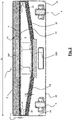
Figure 4 is a cross-sectional view of the base plate of the suction head according toFigure 1 ; -
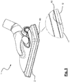
Figures 5 and6 are an axonometric views of a second embodiment of the invention; and -
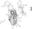
Figures 7 and8 are axonometric views of a third embodiment of the invention. -
Figure 1 shows by way of example a first embodiment of asuction head 1 of a vacuum cleaner or the like with abase plate 2 mounted in accordance with an embodiment of the present invention. - The
suction head 1 according to the invention is particularly suitable for vacuuming surfaces such as carpets, rugs, doormats, matting or the like. However, it is also effective for smooth and compact surfaces such as floors made of stone (marble or the like), terracotta, clinker, cement, resin, tiles, parquet or the like, in particular when used together with bristles and/or extruded (or co-moulded) profiles which may vary their configuration according to needs. - As shown in the various figures, the base plate has a
lower face 2A directed towards the surface to be vacuumed and an oppositeupper face 2B which is connected to thebrush body 8 or to other components of the suction head. - The
suction head 1 has asuction channel 4 which, during use, is joined to thebase plate 2 and is fluid communication with abase plate channel 3 and optionally a covering body which can be connected to the base plate and/or to the suction channel. The other end of thesuction channel 3 communicates with a suction tube usually via a joint 7 which may be rotatable or non-rotatable. - The
base plate 2 may have any form, but typically has a roughly rectangular shape with afront side 21, arear side 22 and two shorterlateral sides - According to the first embodiment, the
base plate channel 3 has afront edge 31, arear edge 32 and twoend edges - As shown in
Figure 1 and inFigures 1.1 and1.2 , thebase plate channel 3 has afront surface 311 inclined at an angle β (beta) relative to the surface connecting thefront edge 31 and therear edge 32. - The
base plate channel 3 has arear surface 321 inclined substantially of the same angle β (beta) with respect to the surface connecting thefront edge 31 and therear edge 32. The inclination of the two front and back surfaces is such that the two surfaces converge upwards. The value of the angle β is less than 90° and is preferably greater than 80°. More preferably, the angle β is between 82° and 86°. Even more preferably it is between 83° and 85°. - As shown in
Figure 1 and, even more clearly inFigure 1.1 , to increase the forward scraping effect, thefront edge 311 is shaped with a nose 31' facing therear edge 31. - According to the present invention, the lower face of the base plate comprises a first front flat surface H1 and a second rear flat surface H2. The first and second flat surfaces H1, H2 lie in the same plane. This common plane of lying substantially coincides with the plane of the surface to be vacuumed or is substantially parallel thereto and at a minimum distance therefrom.
- According to the alternative embodiment of
Figure 1.2 , thefront surface 311 form substantially a sharp edge with the front flat surface H1, i.e. with a minimum radius of curvature, necessary for production reasons. For example, the radius of curvature is 1 mm or less. Such a sharp edge increases the scraping effect over the known embodiments having curved edges, as for instanceEP 1964501 . As shown inFigure 1 and inFigures 1.1 and1.2 , therear surface 321 form a sharp edge with the rear flat surface H2. Also this rear sharp edge increases scraping effect when the nozzle is moved backwardly. - The first flat surface H1 is delimited by the
front edge 31 of thebase plate channel 3 and extends towards thefront side 21 of thebase plate 2 over a first length L1. The first length L1 may be between 1.0 mm and 10.0 mm. However, according to embodiments, L1 is less than 5.0 mm. According to other embodiments, L1 is less than 4.0 mm. Preferably it is greater than 2.0 mm. According to a preferred embodiment, L1 is between 2.5 and 3.0 mm. In any case, the first flat surface extends over an area such as to ensure suitable sealing of the mouth of the base plate channel when the suction head is in contact with the surface to be vacuumed (which may be for example a carpet, a rug or a surface of this type). Therefore, the first flat surface is a substantially thin surface. - The second flat surface H2 is delimited by the
rear edge 32 of thebase plate channel 3 and extends towards therear side 22 of thebase plate 2 over a second distance L2. The second distance L2 may be a few mm, for example 2.0 - 10.0 mm or more. - According to variants of the first embodiment, the lower face of the base plate also comprises a third lateral flat surface H3 and a fourth lateral flat surface H4.
- The third and fourth flat surfaces extend from the end edges 33 and 34 of the
base plate channel 3 to the respectiveshort sides - According to the present invention, an inclined
front surface 11 is provided in front of the first horizontal flat surface H1. The inclinedfront surface 11 extends from the first flat surface towards thefront side 21, namely the inclined front surface I1 starts directly where the first horizontal flat surface H1 ends, substantially without a curved surface between them. Preferably, the inclinedfront surface 11 extends as far as thefront side 21 of thebase plate 2. - The inclined front surface I1 is inclined with respect to the horizontal at an angle of attack α (alpha), as shown in
Figure 4 and also inFigures 1.1 and1.2 . The value of the angle of inclination is preferably greater than 10°. Preferably it is less than 20°. Preferably, the value of the angle of inclination is between 10° and 15°. The Applicant has carried out various tests varying the angle of inclination and has concluded that an optimum value is between 11° and 14°, for example 12° or 13°. - Owing to this inclined front surface I1, the
front side 21 of thebase plate 2, during use, is raised with respect to the surface to be vacuumed. This raised configuration favours capturing of large-size debris which is not pushed forwards or downwards in the event of surfaces with bristles (such as rugs or carpets). In addition, the inclined front surface I1 provides a "surf effect" on carpets or the like. Namely, it increases the capability to surf and slide on carpets, rugs, doormats, matting or the like. - The Applicant has in particular established that the inclination of the inclined front surface I1 must be such as to raise the
front side 21 of a height P1 equal to some millimetres, for example 2-5 mm. Raising by more than 5 mm was considered to be excessive. Raising by less than 1 mm was unable to ensure the efficient suction of large-size debris of the type mentioned above. According to preferred embodiments, thefront side 21 is preferably raised by 3-4 mm, for example 3.5 mm. - Preferably, an inclined rear surface I2 is provided at the rear with respect to the second horizontal flat surface H2. The inclined rear surface I2 extends from the second flat surface to the rear side 212, i.e. the inclined rear surface I2 starts directly where the second horizontal flat surface H2 ends, substantially without a curved surface between them. Preferably, the inclined
rear surface 12 extends up to therear side 22 of thebase plate 2. - The inclined
rear surface 12 is inclined with respect to the horizontal plane of a rear angle of attack γ (gamma) as shown inFigure 4 and also inFigures 1.1 and1.2 is smaller than the front angle of attack α. The value of the rear angle of attack γ is preferably less than 10°. Preferably, it is greater than 5°. Preferably, the value of the rear angle of attack is between 6° and 8°. Also the inclined back surface I2 provides a "surf effect" on carpets or the like when the nozzle is moved backwardly. The nozzle becomes less attracted to the carpet. - According to embodiments of the present invention, there may be strips of velvet (or other similar material suitable for capturing very fine dust or small-size material) 36F, 36R along (at least) the central part of the
base plate channel 3. Preferably there is a front strip ofvelvet 36F which is inset with respect to the inclined front surface I1 and a rear strip ofvelvet 36F which is inset with respect to the second (rear) flat surface H2. In the present description and in the claims, the term "velvet" is used to indicate not only velvet, but also (synthetic or natural) felt or in any case a surface suitable for capturing and trapping particularly small particles (for example fine dust). - Preferably, as shown in
Figures 2-4 , the base plate is provided with tworear wheels 9 for favouring the movement of the suction head over the surface to be vacuumed. During the movement of the suction head, thebase plate 2 of the suction head makes sliding contact with the surface to be vacuumed along the first and second flat horizontal surfaces H1, H2 (as well as the fourth and fifth flat surfaces H3 and H4) and rests on therear wheels 9. Therear wheels 9 project at the bottom only over a small height or in any case such as to keep the horizontal flat surfaces H1 and H2 in contact with the surface to be vacuumed. -
Figures 5 and6 show a second embodiment of the present invention. The suction head of the second embodiment is identical to the suction head of the first embodiment and will not be described again in detail. The difference lies in the fact that thebase plate channel 3 is not closed at the ends, but has at least onehole 60 formed in at least one of the two ends. The hole may be circular (as shown inFigures 5 and6 ), oval, square, rectangular or any other shape. The purpose of thehole 60 is to reduce the suction power which tends to cause the suction head "to stick" on the ground with a suction effect. Due to theholes 60, the suction pressure diminishes and reduces correspondingly the force needed to move the suction head forwards and backwards. Preferably, a strip of material not smaller than 2 mm, preferably not smaller than 2.5 mm, is provided underneath thehole 60 so as not to weaken the end zone of the base plate channel. Depending on the surface to be vacuumed, the holes may also be at least partially closed, for example with a small stopper or the like (not shown). -
Figures 7 and8 show a third embodiment of the present invention. The suction head of the third embodiment is identical to the suction head of the first embodiment and will not be described again in detail. The difference lies in the fact that thebase plate channel 3 is not closed at the ends, but has at least oneaperture 61 formed in at least one of the two ends. Theaperture 61, differently from thehole 60, does not have a bottom closing side, facing the surface to be vacuumed. The purpose of theaperture 61 is to reduce the suction power which tends to cause the suction head "to stick" on the floor with a suction effect. Due to theapertures 61, the suction pressure diminishes and reduces correspondingly the force needed to move the suction head forwards and backwards. Depending on the surface to be vacuumed, the apertures may be at least partially closed, for example with a small stopper or the like (not shown).
According to other embodiments, not shown, one end of thechannel 3 has a hole and the other end has an aperture.
Claims (15)
- A base plate (2) for a suction head (1) for a vacuum cleaner comprising a lower face (2A) configured so as to be directed towards a surface to be vacuumed, an opposite upper face (2B) and a base plate channel (3) open towards the surface to be vacuumed,
wherein said lower face (2A) consists of a single surface delimited by a perimeter comprising a front side (21), a rear side (22) and two lateral sides (23, 24), wherein said base plate (2), during use, is joined to a suction channel (4) and said base plate channel (3) is in fluid communication with the suction channel (4),
wherein said base plate channel (3) extends substantially across the whole width of said base plate (2),
wherein the base plate channel (3) comprises a front edge (31) and a rear edge (32),
wherein the lower face (2A) comprises:a first surface (H1) extending along the entire front edge (31) of the base plate channel (3);a second surface (H2) extending along the entire rear edge (32) of the base plate channel (3), wherein the first and second surfaces (H1, H2) lie in the same horizontal plane; anda front inclined surface (I1) extending from said first surface (H1) towards the front side (21);wherein said front inclined surface (I1) is inclined upwards so that the front side (21) is raised with respect to the surface to be vacuumed; and
wherein said front inclined surface (I1) is inclined of a front angle of attack (α) of between 10° and 20° - The base plate (2) of claim 1, wherein said front inclined surface (I1) is inclined at an angle of attack (α) of between 11° and 14°.
- The base plate (2) of claim 1 or 2, wherein said front inclined surface (I1) extends directly from the most forward edge of the first surface (H1), without any curved surface between said front inclined surface (I1) and said first surface (H1).
- The base plate (2) of claim 1, 2 or 3, wherein the front side (21) is raised by 2.0 - 5.0 mm from the surface to be vacuumed.
- The base plate (2) of any of the preceding claims, wherein said first surface (H1) extends by 1.0 to 10.0 mm towards said front side (21).
- The base plate (2) of any one of the preceding claims, wherein said second surface (H2) extends by 2.0 to 10.0 mm towards said rear side (22).
- The base plate (2) of any one of the preceding claims, comprising also a rear inclined surface (12) which extends from said second flat surface (H2) to the rear side (22).
- The base plate (2) according to claim 7, wherein said rear inclined surface (I2) is inclined of a rear angle of attack (γ) smaller than the front angle of attack (α).
- The base plate (2) of claim 7 or 8, wherein said rear inclined surface (I2) extends directly from the rearmost edge of the second flat surface (H2), without any curved surface between said rear inclined surface (I2) and said second flat surface (H2).
- The base plate (2) of any one of the preceding claims, wherein the base plate channel (3) has a front surface (311) inclined at an angle (β) relative to the surface connecting the front edge (31) and the rear edge (32) and wherein the base plate channel (3) has a rear surface (321) inclined substantially of the same angle (β) with respect to the surface connecting the front edge (31) and the rear edge (32).
- The base plate (2) of claim 10, wherein the front edge (31) is shaped with a nose (31') facing the rear edge (32).
- The base plate (2) of any one of the preceding claims, wherein said channel (3) has closed ends at the lateral sides (23, 24) of said base plate (2) and wherein said base plate comprises also a third and a fourth horizontal flat surface (H3, H4) extending from the end edges (33, 34) of the base plate channel (3) to the respective short sides (23, 24) of the base plate so that a single flat surface formed by the first flat surface (H1), the second flat surface (H2), the third flat surface (H3) and the fourth flat surface (H4) is formed around the whole perimeter of the base plate channel.
- The base plate (2) of any one of claims 1-12, wherein at least one end of said channel (3) comprises a hole (60) or an aperture (61).
- The base plate (2) of any one of the preceding claims, further comprising a first strip (36F) of velvet or the like on said front inclined surface (I1) and a second strip (36R) of velvet or the like on said flat rear surface (H2).
- A suction head (1) comprising a base plate (2) with a base plate channel (3) which is open towards a surface to be vacuumed, a suction channel (4) in fluid communication with the channel (3) of the base plate and a covering body (8) connected to at least one of said base plate (2) and said suction channel (4),
wherein the base plate (2) has a lower face (2A) configured to be directed towards the surface to be vacuumed and an opposite upper face (2B), the base plate channel (3) comprising a front edge (31) and a rear edge (32),
wherein said lower face (2A) consists of a single surface delimited by a perimeter comprising a front side, a rear side and two lateral sides,
wherein said base plate channel (3) extends substantially across the whole width of said base plate (2),
wherein the lower face (2B) comprises:a first surface (H1) extending along the entire front edge (31) of the base plate channel (3);a second surface (H2) extending along the entire rear edge (32) of the base plate channel (3), wherein the first and second surfaces (H1, H2) lie in the same horizontal plane; anda front inclined surface (I1) extending from said first surface (H1) towards the front side (21);wherein said front inclined surface (I1) is inclined upwardly so that the front side (21) is raised with respect to the surface to be vacuumed, and
wherein said front inclined surface (I1) is inclined by a front angle of attack (α) comprised between 10° and 20°.
Applications Claiming Priority (1)
| Application Number | Priority Date | Filing Date | Title |
|---|---|---|---|
| IT201700142414 | 2017-12-11 |
Publications (2)
| Publication Number | Publication Date |
|---|---|
| EP3494852A1 true EP3494852A1 (en) | 2019-06-12 |
| EP3494852B1 EP3494852B1 (en) | 2020-07-22 |
Family
ID=61656232
Family Applications (1)
| Application Number | Title | Priority Date | Filing Date |
|---|---|---|---|
| EP18211202.9A Active EP3494852B1 (en) | 2017-12-11 | 2018-12-10 | Base plate for a vacuum cleaner suction head for the suction of fine dust and large debris |
Country Status (6)
| Country | Link |
|---|---|
| US (1) | US11224319B2 (en) |
| EP (1) | EP3494852B1 (en) |
| CN (1) | CN109893030B (en) |
| DK (1) | DK3494852T3 (en) |
| ES (1) | ES2826573T3 (en) |
| HU (1) | HUE051317T2 (en) |
Cited By (2)
| Publication number | Priority date | Publication date | Assignee | Title |
|---|---|---|---|---|
| EP3760091A1 (en) * | 2019-07-02 | 2021-01-06 | Miele & Cie. KG | Sliding base, vacuum cleaner nozzle and vacuum cleaner |
| SE2330398A1 (en) * | 2023-09-12 | 2025-03-13 | Electrolux Ab | Nozzle for a vacuum cleaner and a vacuum cleaner having such a nozzle |
Families Citing this family (5)
| Publication number | Priority date | Publication date | Assignee | Title |
|---|---|---|---|---|
| US11224319B2 (en) | 2017-12-11 | 2022-01-18 | New Ermes Europe S.R.L. | Base plate for a vacuum cleaner suction head for the suction of fine dust and large debris |
| JP1641037S (en) | 2018-09-18 | 2019-09-09 | ||
| IT202000001555A1 (en) | 2020-01-28 | 2021-07-28 | New Ermes Europe Srl | Adapter device for cordless electric vacuum cleaner |
| USD953673S1 (en) | 2020-02-17 | 2022-05-31 | New Ermes Europe S.R.L. | Head of a vacuum cleaner |
| CN116634912A (en) | 2020-12-23 | 2023-08-22 | 新埃莫斯欧洲有限责任公司 | electric suction head |
Citations (11)
| Publication number | Priority date | Publication date | Assignee | Title |
|---|---|---|---|---|
| DE19906137C1 (en) * | 1999-02-13 | 2000-07-20 | Wessel Werk Gmbh | Slide plate for vacuum cleaner nozzle has insert in recess or aperture with bottom profile forming active suction flow edge for flow channel |
| WO2002026097A1 (en) | 2000-09-28 | 2002-04-04 | Dyson Limited | A floor tool |
| WO2005096907A1 (en) | 2004-04-08 | 2005-10-20 | Grey Technology Limited | Surface cleaning apparatus |
| EP1964501A2 (en) | 2007-03-01 | 2008-09-03 | Wessel-Werk Gmbh | Sheet metal sliding base plate for vacuum cleaner nozzle |
| GB2471918A (en) | 2009-07-16 | 2011-01-19 | Dyson Technology Ltd | A surface treating head |
| GB2496663A (en) | 2011-11-18 | 2013-05-22 | Dyson Technology Ltd | Cleaner head for a vacuum cleaner |
| US20140033473A1 (en) | 2012-08-03 | 2014-02-06 | Dyson Technology Limited | Floor tool for a vacuum cleaning appliance |
| EP2995234A1 (en) | 2014-08-28 | 2016-03-16 | New Ermes Europe S.r.l. | Suction nozzle for a vacuum cleaner or the like with dust-raising device |
| EP3047775A1 (en) | 2015-01-23 | 2016-07-27 | Wessel-Werk GmbH | Sliding sole made from plastic for a vacuum cleaner nozzle |
| EP3087890A1 (en) | 2015-04-29 | 2016-11-02 | Seb S.A. | Vacuum cleaner nozzle flange |
| EP3207848A1 (en) | 2016-02-19 | 2017-08-23 | New Ermes Europe S.r.l. | Base plate for a suction head for vacuum cleaners or the like |
Family Cites Families (109)
| Publication number | Priority date | Publication date | Assignee | Title |
|---|---|---|---|---|
| US428023A (en) | 1890-05-13 | Casing for flexible shafts | ||
| US24222A (en) | 1859-05-31 | Suction-hose | ||
| US395671A (en) | 1889-01-01 | Pipe-coupler | ||
| US809977A (en) | 1903-02-02 | 1906-01-16 | Arthur O'brien | Flexible pipe. |
| US1153187A (en) | 1913-08-05 | 1915-09-14 | Edward Francis Berry | Flexible joint. |
| US1434631A (en) | 1921-01-22 | 1922-11-07 | James J Reynolds | Flexible pipe joint |
| US1560789A (en) | 1922-03-25 | 1925-11-10 | Sf Bowser & Co Inc | Hose holder |
| GB220206A (en) | 1923-11-27 | 1924-08-14 | Selina Hamburger | Improvements in adjustable display stands for flowers and the like |
| FR578087A (en) | 1924-03-05 | 1924-09-16 | Kustner Freres Cie Sa | Machine for making so-called sweets |
| GB468920A (en) | 1935-11-26 | 1937-07-15 | Electrolux Ltd | Improvements in nozzles for vacuum cleaners |
| US2249463A (en) | 1939-07-21 | 1941-07-15 | Electric Vacuum Cleaner Co | Suction nozzle |
| US2416418A (en) | 1943-09-27 | 1947-02-25 | Westinghouse Electric Corp | Convertible pneumatic cleaning apparatus |
| US2627623A (en) | 1949-02-15 | 1953-02-10 | Hoover Co | Agitator raiser and belt release for suction cleaners |
| FR1140810A (en) | 1956-02-07 | 1957-08-14 | Flexible tube for dust extractors | |
| US2915774A (en) | 1957-05-20 | 1959-12-08 | Gen Electric | Turbine drive surface cleaner with integral generator |
| US3266059A (en) | 1963-06-19 | 1966-08-16 | North American Aviation Inc | Prestressed flexible joint for mechanical arms and the like |
| US3245228A (en) | 1964-04-03 | 1966-04-12 | Eaton Mfg Co | Universal joint |
| FR1501935A (en) | 1966-09-29 | 1967-11-18 | Olivier Ets Georges | Improvements to vacuum cleaners |
| US3855666A (en) | 1972-09-25 | 1974-12-24 | Electrolux Ab | Vacuum cleaner |
| GB2072495B (en) | 1980-03-25 | 1983-11-30 | Wessel H | Vacuum cleaner nozzles |
| US4319379A (en) | 1980-04-29 | 1982-03-16 | Carrigan William J | Pickup |
| US4336628A (en) | 1980-06-05 | 1982-06-29 | The Hoover Company | Nozzle with pivoted wand |
| AT383264B (en) | 1980-10-01 | 1987-06-10 | Walkner & Co Ohg Dr H & A | CLEANING DEVICE FOR TEXTILE MATERIAL, FOR CONNECTION TO AN AIR EXTRACTION DEVICE |
| FR2546054B1 (en) | 1983-05-17 | 1985-08-30 | Olivier Ets Georges | ROLLER VACUUM CLEANER |
| DE8436154U1 (en) | 1984-12-11 | 1985-04-25 | Vorwerk & Co Interholding Gmbh, 5600 Wuppertal | SUCTION HOSE FOR VACUUM CLEANERS |
| DE8604732U1 (en) | 1986-02-21 | 1987-06-19 | Siemens AG, 1000 Berlin und 8000 München | Vacuum cleaner mouthpiece with a pivoting connection piece and a mouthpiece body |
| US4777696A (en) | 1986-07-17 | 1988-10-18 | The Regina Co., Inc. | Vacuum cleaner nozzle |
| DE3737568A1 (en) | 1987-11-05 | 1989-05-18 | Siegfried Maier | CONTROL DEVICE FOR THE BRUSHES OF A CLEANING DEVICE |
| DE4000374A1 (en) | 1989-01-31 | 1990-08-02 | Duepro Ag | MULTI-PURPOSE SUCTION NOZZLE |
| DE8901995U1 (en) | 1989-02-20 | 1990-06-28 | Siemens AG, 1000 Berlin und 8000 München | Insert joint |
| USD333539S (en) | 1989-09-01 | 1993-02-23 | Wessel-Werk Gmbh | Suction cleaner nozzle |
| JPH03149489A (en) | 1989-11-02 | 1991-06-26 | Fujitsu Ltd | Coupler for connection of gas piping |
| DE4028113A1 (en) | 1990-09-05 | 1992-03-12 | Licentia Gmbh | Floor-cleaning nozzle attachment for hand vacuum cleaner - is secured releasably by latch with pins engaging brackets on either side of leaf-sprung lever |
| DE4105012C2 (en) | 1991-02-19 | 1994-09-29 | Fedag Romanshorn Fa | Vacuum cleaner mouthpiece |
| DE4105336C2 (en) | 1991-02-21 | 1994-08-25 | Fedag Romanshorn Fa | Suction cleaning tool |
| US5069569A (en) | 1991-05-09 | 1991-12-03 | Ferro Tools Inc. | Universal joint |
| DE4201596C2 (en) | 1992-01-22 | 2001-07-05 | Gerhard Kurz | Floor nozzle for vacuum cleaners |
| DE4204749C1 (en) | 1992-02-18 | 1993-10-28 | Fedag Romanshorn Fa | Suction cleaning tool for wet and dry vacuum cleaners |
| DE4403971B4 (en) | 1993-06-25 | 2007-03-01 | Vorwerk & Co. Interholding Gmbh | Floor suction device, in particular intent or part of an electric vacuum cleaner |
| JP2526509B2 (en) | 1993-10-14 | 1996-08-21 | マルホ産業株式会社 | Underground electric wire burying protection tube |
| DE4413071C2 (en) | 1994-04-15 | 1999-07-15 | Kurt Zachhuber | Mouthpiece |
| FR2732884B1 (en) | 1995-04-13 | 1997-07-04 | Olivier Ets Georges | VACUUM CLEANER WITH REAR WHEELS |
| JPH08322766A (en) | 1995-05-30 | 1996-12-10 | Hitachi Ltd | Electric vacuum cleaner |
| EP0780085A1 (en) | 1995-12-21 | 1997-06-25 | Walter Fust | Vacuum cleaner and suction nozzle |
| GB9603250D0 (en) | 1996-02-16 | 1996-04-17 | Vax Ltd | Cleaning heads and adaptors for the use therewith |
| DE19617415C2 (en) | 1996-05-01 | 2001-06-21 | Wessel Werk Gmbh | Suction head on a vacuum cleaner |
| DE29608726U1 (en) | 1996-05-14 | 1996-07-11 | Siemens AG, 80333 München | Vacuum cleaner mouthpiece |
| DE19704796C1 (en) | 1997-02-08 | 1998-01-15 | Wessel Werk Gmbh | Vacuum cleaner nozzle with low-noise characteristics |
| US5740839A (en) | 1997-03-25 | 1998-04-21 | Kuo; Hsien-Jen | Flexible extension conduit |
| USD392780S (en) | 1997-05-16 | 1998-03-24 | Emerson Electric Co. | Vacuum cleaner nozzle |
| DE19745479C1 (en) | 1997-10-15 | 1999-04-29 | Aeg Hausgeraete Gmbh | Floor nozzle for a cleaning device, in particular for a vacuum cleaner |
| USD424766S (en) | 1998-01-26 | 2000-05-09 | Emerson Electric Co. | Multi-use vacuum nozzle |
| DE59907302D1 (en) | 1998-06-12 | 2003-11-13 | Duepro Ag Romanshorn | vacuum cleaning tool |
| US6675438B2 (en) | 1999-02-19 | 2004-01-13 | Wessel-Werke Gmbh | Vacuum-cleaner floor head |
| EP1031312A1 (en) | 1999-02-22 | 2000-08-30 | POLTI S.p.A. | Articulation for pipes in cleaning appliances |
| DE19912651A1 (en) | 1999-03-20 | 2000-09-21 | Wessel Werk Gmbh | Vacuum cleaner has solar cells mounted on exterior of housing to charge up rechargeable accumulator for supplying electrical power to motor for driving brush roller in suction channel |
| DE19915035C2 (en) | 1999-04-01 | 2001-08-09 | Kabelschlepp Gmbh | Line guiding element for guiding at least one line |
| DK1176902T3 (en) | 1999-04-30 | 2009-02-23 | Johan Adolf Bystroem | coupling device |
| DE10000504C2 (en) | 2000-01-08 | 2002-11-07 | Wessel Werk Gmbh | Suction head for vacuum cleaner |
| ATE264648T1 (en) | 2000-01-28 | 2004-05-15 | New Ermes Europe Spa | DUST AND WASTE REMOVAL DEVICE |
| JP3457639B2 (en) | 2000-05-04 | 2003-10-20 | エルジー電子株式会社 | Vacuum cleaner |
| SE516615C2 (en) | 2000-06-21 | 2002-02-05 | Johan Adolf Bystroem | Bendable joint |
| USD457696S1 (en) | 2000-08-02 | 2002-05-21 | Düpro AG | Vacuum cleaning tool |
| EP1210898B1 (en) | 2000-11-22 | 2004-03-24 | Wessel-Werk Gmbh | Nozzle for vacuum cleaner for cleaning floors, in particular household vacuum cleaner |
| FR2821540B1 (en) | 2001-03-05 | 2004-03-19 | Millet Marius | VACUUM CLEANER WITH SUPPORT SCRAPER |
| DE10111867A1 (en) | 2001-03-13 | 2002-09-19 | Vorwerk Co Interholding | Tilting joint formation of a vacuum cleaner suction channel |
| USD456967S1 (en) | 2001-05-01 | 2002-05-07 | Bissell Homecare, Inc. | Vacuum cleaner foot |
| USD466499S1 (en) | 2001-07-20 | 2002-12-03 | Sony Corporation | Computer |
| ITMO20010215A1 (en) | 2001-11-13 | 2003-05-13 | Next At Srl | ARTICULATED JOINT FOR RIGID PIPES SUPPLIED TO HOUSEHOLD APPLIANCES |
| ITMI20021567A1 (en) | 2002-07-16 | 2004-01-16 | New Ermes Europe Spa | ARTICULATED JOINT FOR HOUSEHOLD APPLIANCES AND HOUSEHOLD APPLIANCES INCLUDING SUCH JOINT |
| USD484287S1 (en) | 2003-01-10 | 2003-12-23 | Royal Appliance Mfg. Co. | Suction nozzle |
| DE10312906B4 (en) | 2003-02-20 | 2006-05-04 | Wessel-Werk Gmbh | Staubstaugerdüse for smooth floors and textile floor coverings |
| EP1449476B1 (en) | 2003-02-20 | 2008-08-27 | Wessel-Werk Gmbh | Nozzle for smooth surfaces and for textile floor coverings |
| USD507854S1 (en) | 2003-10-17 | 2005-07-26 | Lg Electronics Inc. | Suction nozzle for vacuum cleaner |
| US6981338B2 (en) | 2003-12-23 | 2006-01-03 | Jensen Dale S | Device for improved removal of liquid from fabric |
| EP1595485B1 (en) | 2004-05-10 | 2007-03-28 | Wessel-Werk GmbH & Co. KG | Nozzle for vaccum cleaner |
| ITMI20041075A1 (en) | 2004-05-28 | 2004-08-28 | New Ermes Europe Spa | IMPROVED MECHANISM FOR HANDLING A RUBBING-LIFTING INSERTS IN A VACUUM HEAD FOR VACUUM CLEANERS |
| ITMI20041074A1 (en) | 2004-05-28 | 2004-08-28 | New Ermes Europe Spa | ASPIRATION HEAD FOR DUST VACUUM OR SIMILAR WITH SEPARABLE SUCTION DUCT |
| KR100642076B1 (en) | 2004-07-01 | 2006-11-10 | 삼성광주전자 주식회사 | Suction structure assembly and vacuum cleaner with same |
| USD518259S1 (en) | 2004-09-13 | 2006-03-28 | Robert Wertz | Vacuum attachment |
| AU305340S (en) | 2004-10-08 | 2006-02-07 | Dyson Technology Ltd | An accessory for a cleaning appliance |
| DE102004061971B4 (en) | 2004-12-23 | 2012-04-26 | Wessel-Werk Gmbh | Floor nozzle for vacuum cleaner |
| US8117714B2 (en) | 2005-03-09 | 2012-02-21 | Bissell Homecare, Inc. | Vacuum cleaner with hair collection element |
| ITMO20050151A1 (en) | 2005-06-14 | 2006-12-15 | Pineschi Massimiliano | VACUUM CLEANER. |
| USD543669S1 (en) | 2005-07-11 | 2007-05-29 | Sanyo Electric Co., Ltd. | Nozzle of electric vacuum cleaner |
| KR20070008946A (en) | 2005-07-14 | 2007-01-18 | 삼성전자주식회사 | Display device and portable wireless terminal having same |
| USD556963S1 (en) | 2006-02-06 | 2007-12-04 | Black & Decker Inc. | Floor head for a vacuum cleaner |
| USD599065S1 (en) | 2006-08-23 | 2009-08-25 | New Ermes Europe S.P.A. | Vacuum cleaner suction nozzle |
| US7798177B1 (en) | 2006-09-07 | 2010-09-21 | Superior Tire & Rubber Corporation | Removable transition sleeve for a transition tube of a vacuum sweeper |
| DE102008010897A1 (en) | 2008-02-23 | 2009-08-27 | Wessel-Werk Gmbh | Nozzle for vacuum cleaner |
| USD635728S1 (en) | 2008-10-21 | 2011-04-05 | Aktiebolaget Electrolux | Vacuum cleaner |
| WO2010081186A1 (en) | 2009-01-19 | 2010-07-22 | Adc Gmbh | Telecommunications connector |
| KR101338268B1 (en) | 2009-06-17 | 2013-12-11 | 다이슨 테크놀러지 리미티드 | A tool for a surface treating appliance |
| DE102010043515B4 (en) | 2010-11-05 | 2014-10-16 | BSH Bosch und Siemens Hausgeräte GmbH | Suction nozzle arrangement and vacuum cleaner |
| USD672103S1 (en) | 2010-12-22 | 2012-12-04 | Dyson Limited | Part of a vacuum cleaner |
| USD741559S1 (en) | 2013-05-02 | 2015-10-20 | Techtronic Floor Care Technology Limited | Floor cleaning tool |
| USD775443S1 (en) | 2014-01-03 | 2016-12-27 | Samsung Electronics Co., Ltd. | Brush for cleaner |
| DK2944242T3 (en) | 2014-05-14 | 2019-11-11 | New Ermes Europe Srl | Suction head for a vacuum cleaner or similar with improved base plate channel |
| GB2532961B (en) | 2014-12-02 | 2017-03-22 | Dyson Technology Ltd | Floor tool for a vacuum cleaner |
| JP1543696S (en) | 2014-12-11 | 2018-01-29 | ||
| USD787766S1 (en) | 2015-02-23 | 2017-05-23 | Lg Electronics Inc. | Nozzle for vacuum cleaner |
| USD789007S1 (en) | 2015-03-12 | 2017-06-06 | Samsung Electronics Co., Ltd | Intake for cleaner |
| USD796136S1 (en) | 2015-06-03 | 2017-08-29 | Ac (Macao Commercial Offshore) Limited | Floorhead |
| ITUA20162159A1 (en) | 2016-03-31 | 2017-10-01 | New Ermes Europe Srl | Suction head with perfected suction channel |
| ITUA20163223A1 (en) | 2016-05-06 | 2017-11-06 | New Ermes Europe Srl | Suction head with improved adherence to the surface to be aspirated |
| JP1581451S (en) | 2016-09-06 | 2017-07-18 | ||
| JP1608643S (en) | 2017-08-03 | 2018-07-09 | ||
| US11224319B2 (en) | 2017-12-11 | 2022-01-18 | New Ermes Europe S.R.L. | Base plate for a vacuum cleaner suction head for the suction of fine dust and large debris |
| US20190174983A1 (en) | 2017-12-11 | 2019-06-13 | New Ermes Europe S.R.L. | Accessory for a vacuum cleaner suction head for collecting large debris |
-
2018
- 2018-12-06 US US16/211,730 patent/US11224319B2/en active Active
- 2018-12-10 HU HUE18211202A patent/HUE051317T2/en unknown
- 2018-12-10 ES ES18211202T patent/ES2826573T3/en active Active
- 2018-12-10 DK DK18211202.9T patent/DK3494852T3/en active
- 2018-12-10 EP EP18211202.9A patent/EP3494852B1/en active Active
- 2018-12-11 CN CN201811506940.2A patent/CN109893030B/en active Active
Patent Citations (11)
| Publication number | Priority date | Publication date | Assignee | Title |
|---|---|---|---|---|
| DE19906137C1 (en) * | 1999-02-13 | 2000-07-20 | Wessel Werk Gmbh | Slide plate for vacuum cleaner nozzle has insert in recess or aperture with bottom profile forming active suction flow edge for flow channel |
| WO2002026097A1 (en) | 2000-09-28 | 2002-04-04 | Dyson Limited | A floor tool |
| WO2005096907A1 (en) | 2004-04-08 | 2005-10-20 | Grey Technology Limited | Surface cleaning apparatus |
| EP1964501A2 (en) | 2007-03-01 | 2008-09-03 | Wessel-Werk Gmbh | Sheet metal sliding base plate for vacuum cleaner nozzle |
| GB2471918A (en) | 2009-07-16 | 2011-01-19 | Dyson Technology Ltd | A surface treating head |
| GB2496663A (en) | 2011-11-18 | 2013-05-22 | Dyson Technology Ltd | Cleaner head for a vacuum cleaner |
| US20140033473A1 (en) | 2012-08-03 | 2014-02-06 | Dyson Technology Limited | Floor tool for a vacuum cleaning appliance |
| EP2995234A1 (en) | 2014-08-28 | 2016-03-16 | New Ermes Europe S.r.l. | Suction nozzle for a vacuum cleaner or the like with dust-raising device |
| EP3047775A1 (en) | 2015-01-23 | 2016-07-27 | Wessel-Werk GmbH | Sliding sole made from plastic for a vacuum cleaner nozzle |
| EP3087890A1 (en) | 2015-04-29 | 2016-11-02 | Seb S.A. | Vacuum cleaner nozzle flange |
| EP3207848A1 (en) | 2016-02-19 | 2017-08-23 | New Ermes Europe S.r.l. | Base plate for a suction head for vacuum cleaners or the like |
Cited By (4)
| Publication number | Priority date | Publication date | Assignee | Title |
|---|---|---|---|---|
| EP3760091A1 (en) * | 2019-07-02 | 2021-01-06 | Miele & Cie. KG | Sliding base, vacuum cleaner nozzle and vacuum cleaner |
| SE2330398A1 (en) * | 2023-09-12 | 2025-03-13 | Electrolux Ab | Nozzle for a vacuum cleaner and a vacuum cleaner having such a nozzle |
| EP4523588A1 (en) * | 2023-09-12 | 2025-03-19 | Aktiebolaget Electrolux | Nozzle for a vacuum cleaner and a vacuum cleaner having such a nozzle |
| SE547527C2 (en) * | 2023-09-12 | 2025-09-14 | Electrolux Ab | Nozzle for a vacuum cleaner and a vacuum cleaner having such a nozzle |
Also Published As
| Publication number | Publication date |
|---|---|
| US11224319B2 (en) | 2022-01-18 |
| CN109893030A (en) | 2019-06-18 |
| CN109893030B (en) | 2022-04-05 |
| ES2826573T3 (en) | 2021-05-18 |
| US20190174981A1 (en) | 2019-06-13 |
| EP3494852B1 (en) | 2020-07-22 |
| DK3494852T3 (en) | 2020-10-19 |
| HUE051317T2 (en) | 2021-03-01 |
Similar Documents
| Publication | Publication Date | Title |
|---|---|---|
| EP3494852B1 (en) | Base plate for a vacuum cleaner suction head for the suction of fine dust and large debris | |
| EP3510908B1 (en) | Accessory for a vacuum cleaner suction head for collecting large debris | |
| US7069620B2 (en) | Floor tool | |
| EP3207848B1 (en) | Base plate for a suction head for vacuum cleaners or the like | |
| CN103826517B (en) | The suction nozzle of dust catcher | |
| US10765281B2 (en) | Suction head for a vacuum cleaner and method of operation | |
| GB2468514A (en) | Surface treating head | |
| AU2001287872A1 (en) | A floor tool | |
| EP2995234B1 (en) | Suction nozzle for a vacuum cleaner or the like with dust-raising device | |
| EP3181029A1 (en) | Vacuum cleaner nozzle | |
| CN210300848U (en) | Dust collector suction nozzle and household dust collector comprising same | |
| EP3284380B1 (en) | Vacuum cleaner head | |
| EP2989954B1 (en) | Accessory for a suction nozzle of vacuum cleaners or the like | |
| HK40010127A (en) | Base plate for a vacuum cleaner suction head for the suction of fine dust and large debris | |
| HK40010127B (en) | Base plate for a vacuum cleaner suction head for the suction of fine dust and large debris | |
| US11786090B2 (en) | Floor nozzle for a vacuum cleaner and vacuum cleaner | |
| EP3151711B1 (en) | Nozzle with three settings | |
| HK1236782A1 (en) | Base plate for a suction head for vacuum cleaners or the like | |
| HK1217625B (en) | Accessory for a suction nozzle of vacuum cleaners or the like |
Legal Events
| Date | Code | Title | Description |
|---|---|---|---|
| PUAI | Public reference made under article 153(3) epc to a published international application that has entered the european phase |
Free format text: ORIGINAL CODE: 0009012 |
|
| STAA | Information on the status of an ep patent application or granted ep patent |
Free format text: STATUS: THE APPLICATION HAS BEEN PUBLISHED |
|
| AK | Designated contracting states |
Kind code of ref document: A1 Designated state(s): AL AT BE BG CH CY CZ DE DK EE ES FI FR GB GR HR HU IE IS IT LI LT LU LV MC MK MT NL NO PL PT RO RS SE SI SK SM TR |
|
| AX | Request for extension of the european patent |
Extension state: BA ME |
|
| STAA | Information on the status of an ep patent application or granted ep patent |
Free format text: STATUS: REQUEST FOR EXAMINATION WAS MADE |
|
| 17P | Request for examination filed |
Effective date: 20191212 |
|
| RBV | Designated contracting states (corrected) |
Designated state(s): AL AT BE BG CH CY CZ DE DK EE ES FI FR GB GR HR HU IE IS IT LI LT LU LV MC MK MT NL NO PL PT RO RS SE SI SK SM TR |
|
| GRAP | Despatch of communication of intention to grant a patent |
Free format text: ORIGINAL CODE: EPIDOSNIGR1 |
|
| STAA | Information on the status of an ep patent application or granted ep patent |
Free format text: STATUS: GRANT OF PATENT IS INTENDED |
|
| RIC1 | Information provided on ipc code assigned before grant |
Ipc: A47L 9/02 20060101ALI20200131BHEP Ipc: A47L 9/06 20060101AFI20200131BHEP |
|
| INTG | Intention to grant announced |
Effective date: 20200228 |
|
| GRAS | Grant fee paid |
Free format text: ORIGINAL CODE: EPIDOSNIGR3 |
|
| GRAA | (expected) grant |
Free format text: ORIGINAL CODE: 0009210 |
|
| STAA | Information on the status of an ep patent application or granted ep patent |
Free format text: STATUS: THE PATENT HAS BEEN GRANTED |
|
| REG | Reference to a national code |
Ref country code: HK Ref legal event code: DE Ref document number: 40010127 Country of ref document: HK |
|
| AK | Designated contracting states |
Kind code of ref document: B1 Designated state(s): AL AT BE BG CH CY CZ DE DK EE ES FI FR GB GR HR HU IE IS IT LI LT LU LV MC MK MT NL NO PL PT RO RS SE SI SK SM TR |
|
| REG | Reference to a national code |
Ref country code: GB Ref legal event code: FG4D |
|
| REG | Reference to a national code |
Ref country code: CH Ref legal event code: EP |
|
| REG | Reference to a national code |
Ref country code: DE Ref legal event code: R096 Ref document number: 602018006250 Country of ref document: DE |
|
| REG | Reference to a national code |
Ref country code: AT Ref legal event code: REF Ref document number: 1292562 Country of ref document: AT Kind code of ref document: T Effective date: 20200815 |
|
| REG | Reference to a national code |
Ref country code: IE Ref legal event code: FG4D |
|
| REG | Reference to a national code |
Ref country code: DK Ref legal event code: T3 Effective date: 20201014 |
|
| REG | Reference to a national code |
Ref country code: SE Ref legal event code: TRGR |
|
| REG | Reference to a national code |
Ref country code: NL Ref legal event code: FP |
|
| REG | Reference to a national code |
Ref country code: CH Ref legal event code: NV Representative=s name: E. BLUM AND CO. AG PATENT- UND MARKENANWAELTE , CH |
|
| REG | Reference to a national code |
Ref country code: LT Ref legal event code: MG4D |
|
| REG | Reference to a national code |
Ref country code: AT Ref legal event code: MK05 Ref document number: 1292562 Country of ref document: AT Kind code of ref document: T Effective date: 20200722 |
|
| PG25 | Lapsed in a contracting state [announced via postgrant information from national office to epo] |
Ref country code: PT Free format text: LAPSE BECAUSE OF FAILURE TO SUBMIT A TRANSLATION OF THE DESCRIPTION OR TO PAY THE FEE WITHIN THE PRESCRIBED TIME-LIMIT Effective date: 20201123 Ref country code: AT Free format text: LAPSE BECAUSE OF FAILURE TO SUBMIT A TRANSLATION OF THE DESCRIPTION OR TO PAY THE FEE WITHIN THE PRESCRIBED TIME-LIMIT Effective date: 20200722 Ref country code: HR Free format text: LAPSE BECAUSE OF FAILURE TO SUBMIT A TRANSLATION OF THE DESCRIPTION OR TO PAY THE FEE WITHIN THE PRESCRIBED TIME-LIMIT Effective date: 20200722 Ref country code: BG Free format text: LAPSE BECAUSE OF FAILURE TO SUBMIT A TRANSLATION OF THE DESCRIPTION OR TO PAY THE FEE WITHIN THE PRESCRIBED TIME-LIMIT Effective date: 20201022 Ref country code: LT Free format text: LAPSE BECAUSE OF FAILURE TO SUBMIT A TRANSLATION OF THE DESCRIPTION OR TO PAY THE FEE WITHIN THE PRESCRIBED TIME-LIMIT Effective date: 20200722 Ref country code: GR Free format text: LAPSE BECAUSE OF FAILURE TO SUBMIT A TRANSLATION OF THE DESCRIPTION OR TO PAY THE FEE WITHIN THE PRESCRIBED TIME-LIMIT Effective date: 20201023 Ref country code: NO Free format text: LAPSE BECAUSE OF FAILURE TO SUBMIT A TRANSLATION OF THE DESCRIPTION OR TO PAY THE FEE WITHIN THE PRESCRIBED TIME-LIMIT Effective date: 20201022 Ref country code: FI Free format text: LAPSE BECAUSE OF FAILURE TO SUBMIT A TRANSLATION OF THE DESCRIPTION OR TO PAY THE FEE WITHIN THE PRESCRIBED TIME-LIMIT Effective date: 20200722 |
|
| PG25 | Lapsed in a contracting state [announced via postgrant information from national office to epo] |
Ref country code: RS Free format text: LAPSE BECAUSE OF FAILURE TO SUBMIT A TRANSLATION OF THE DESCRIPTION OR TO PAY THE FEE WITHIN THE PRESCRIBED TIME-LIMIT Effective date: 20200722 Ref country code: LV Free format text: LAPSE BECAUSE OF FAILURE TO SUBMIT A TRANSLATION OF THE DESCRIPTION OR TO PAY THE FEE WITHIN THE PRESCRIBED TIME-LIMIT Effective date: 20200722 Ref country code: IS Free format text: LAPSE BECAUSE OF FAILURE TO SUBMIT A TRANSLATION OF THE DESCRIPTION OR TO PAY THE FEE WITHIN THE PRESCRIBED TIME-LIMIT Effective date: 20201122 |
|
| REG | Reference to a national code |
Ref country code: HU Ref legal event code: AG4A Ref document number: E051317 Country of ref document: HU |
|
| REG | Reference to a national code |
Ref country code: DE Ref legal event code: R097 Ref document number: 602018006250 Country of ref document: DE |
|
| PG25 | Lapsed in a contracting state [announced via postgrant information from national office to epo] |
Ref country code: RO Free format text: LAPSE BECAUSE OF FAILURE TO SUBMIT A TRANSLATION OF THE DESCRIPTION OR TO PAY THE FEE WITHIN THE PRESCRIBED TIME-LIMIT Effective date: 20200722 Ref country code: CZ Free format text: LAPSE BECAUSE OF FAILURE TO SUBMIT A TRANSLATION OF THE DESCRIPTION OR TO PAY THE FEE WITHIN THE PRESCRIBED TIME-LIMIT Effective date: 20200722 Ref country code: EE Free format text: LAPSE BECAUSE OF FAILURE TO SUBMIT A TRANSLATION OF THE DESCRIPTION OR TO PAY THE FEE WITHIN THE PRESCRIBED TIME-LIMIT Effective date: 20200722 Ref country code: SM Free format text: LAPSE BECAUSE OF FAILURE TO SUBMIT A TRANSLATION OF THE DESCRIPTION OR TO PAY THE FEE WITHIN THE PRESCRIBED TIME-LIMIT Effective date: 20200722 |
|
| REG | Reference to a national code |
Ref country code: ES Ref legal event code: FG2A Ref document number: 2826573 Country of ref document: ES Kind code of ref document: T3 Effective date: 20210518 |
|
| PLBE | No opposition filed within time limit |
Free format text: ORIGINAL CODE: 0009261 |
|
| STAA | Information on the status of an ep patent application or granted ep patent |
Free format text: STATUS: NO OPPOSITION FILED WITHIN TIME LIMIT |
|
| PG25 | Lapsed in a contracting state [announced via postgrant information from national office to epo] |
Ref country code: AL Free format text: LAPSE BECAUSE OF FAILURE TO SUBMIT A TRANSLATION OF THE DESCRIPTION OR TO PAY THE FEE WITHIN THE PRESCRIBED TIME-LIMIT Effective date: 20200722 |
|
| 26N | No opposition filed |
Effective date: 20210423 |
|
| PG25 | Lapsed in a contracting state [announced via postgrant information from national office to epo] |
Ref country code: SK Free format text: LAPSE BECAUSE OF FAILURE TO SUBMIT A TRANSLATION OF THE DESCRIPTION OR TO PAY THE FEE WITHIN THE PRESCRIBED TIME-LIMIT Effective date: 20200722 |
|
| PG25 | Lapsed in a contracting state [announced via postgrant information from national office to epo] |
Ref country code: SI Free format text: LAPSE BECAUSE OF FAILURE TO SUBMIT A TRANSLATION OF THE DESCRIPTION OR TO PAY THE FEE WITHIN THE PRESCRIBED TIME-LIMIT Effective date: 20200722 Ref country code: MC Free format text: LAPSE BECAUSE OF FAILURE TO SUBMIT A TRANSLATION OF THE DESCRIPTION OR TO PAY THE FEE WITHIN THE PRESCRIBED TIME-LIMIT Effective date: 20200722 |
|
| PG25 | Lapsed in a contracting state [announced via postgrant information from national office to epo] |
Ref country code: IE Free format text: LAPSE BECAUSE OF NON-PAYMENT OF DUE FEES Effective date: 20201210 Ref country code: LU Free format text: LAPSE BECAUSE OF NON-PAYMENT OF DUE FEES Effective date: 20201210 |
|
| PG25 | Lapsed in a contracting state [announced via postgrant information from national office to epo] |
Ref country code: MT Free format text: LAPSE BECAUSE OF FAILURE TO SUBMIT A TRANSLATION OF THE DESCRIPTION OR TO PAY THE FEE WITHIN THE PRESCRIBED TIME-LIMIT Effective date: 20200722 Ref country code: CY Free format text: LAPSE BECAUSE OF FAILURE TO SUBMIT A TRANSLATION OF THE DESCRIPTION OR TO PAY THE FEE WITHIN THE PRESCRIBED TIME-LIMIT Effective date: 20200722 |
|
| PG25 | Lapsed in a contracting state [announced via postgrant information from national office to epo] |
Ref country code: MK Free format text: LAPSE BECAUSE OF FAILURE TO SUBMIT A TRANSLATION OF THE DESCRIPTION OR TO PAY THE FEE WITHIN THE PRESCRIBED TIME-LIMIT Effective date: 20200722 |
|
| P01 | Opt-out of the competence of the unified patent court (upc) registered |
Effective date: 20230529 |
|
| REG | Reference to a national code |
Ref country code: CH Ref legal event code: U11 Free format text: ST27 STATUS EVENT CODE: U-0-0-U10-U11 (AS PROVIDED BY THE NATIONAL OFFICE) Effective date: 20260101 |
|
| PGFP | Annual fee paid to national office [announced via postgrant information from national office to epo] |
Ref country code: DE Payment date: 20251211 Year of fee payment: 8 |
|
| PGFP | Annual fee paid to national office [announced via postgrant information from national office to epo] |
Ref country code: GB Payment date: 20251219 Year of fee payment: 8 |
|
| PGFP | Annual fee paid to national office [announced via postgrant information from national office to epo] |
Ref country code: IT Payment date: 20251217 Year of fee payment: 8 Ref country code: DK Payment date: 20251224 Year of fee payment: 8 |
|
| PGFP | Annual fee paid to national office [announced via postgrant information from national office to epo] |
Ref country code: HU Payment date: 20251223 Year of fee payment: 8 Ref country code: NL Payment date: 20251219 Year of fee payment: 8 Ref country code: FR Payment date: 20251229 Year of fee payment: 8 |
|
| PGFP | Annual fee paid to national office [announced via postgrant information from national office to epo] |
Ref country code: TR Payment date: 20251203 Year of fee payment: 8 Ref country code: BE Payment date: 20251219 Year of fee payment: 8 |
|
| PGFP | Annual fee paid to national office [announced via postgrant information from national office to epo] |
Ref country code: SE Payment date: 20251219 Year of fee payment: 8 |
|
| PGFP | Annual fee paid to national office [announced via postgrant information from national office to epo] |
Ref country code: PL Payment date: 20251126 Year of fee payment: 8 |
|
| PGFP | Annual fee paid to national office [announced via postgrant information from national office to epo] |
Ref country code: ES Payment date: 20260130 Year of fee payment: 8 |
|
| PGFP | Annual fee paid to national office [announced via postgrant information from national office to epo] |
Ref country code: CH Payment date: 20260101 Year of fee payment: 8 |