EP3494583B1 - Elektrisches gerät mit unterschiedlich stark gekühlten kapselungsräumen - Google Patents
Elektrisches gerät mit unterschiedlich stark gekühlten kapselungsräumen Download PDFInfo
- Publication number
- EP3494583B1 EP3494583B1 EP17767832.3A EP17767832A EP3494583B1 EP 3494583 B1 EP3494583 B1 EP 3494583B1 EP 17767832 A EP17767832 A EP 17767832A EP 3494583 B1 EP3494583 B1 EP 3494583B1
- Authority
- EP
- European Patent Office
- Prior art keywords
- winding
- insulating fluid
- temperature
- electrical device
- insulating
- Prior art date
- Legal status (The legal status is an assumption and is not a legal conclusion. Google has not performed a legal analysis and makes no representation as to the accuracy of the status listed.)
- Active
Links
Images


Classifications
-
- H—ELECTRICITY
- H01—ELECTRIC ELEMENTS
- H01F—MAGNETS; INDUCTANCES; TRANSFORMERS; SELECTION OF MATERIALS FOR THEIR MAGNETIC PROPERTIES
- H01F27/00—Details of transformers or inductances, in general
- H01F27/08—Cooling; Ventilating
- H01F27/10—Liquid cooling
- H01F27/12—Oil cooling
- H01F27/14—Expansion chambers; Oil conservators; Gas cushions; Arrangements for purifying, drying, or filling
-
- H—ELECTRICITY
- H01—ELECTRIC ELEMENTS
- H01F—MAGNETS; INDUCTANCES; TRANSFORMERS; SELECTION OF MATERIALS FOR THEIR MAGNETIC PROPERTIES
- H01F27/00—Details of transformers or inductances, in general
- H01F27/02—Casings
- H01F27/025—Constructional details relating to cooling
-
- H—ELECTRICITY
- H01—ELECTRIC ELEMENTS
- H01F—MAGNETS; INDUCTANCES; TRANSFORMERS; SELECTION OF MATERIALS FOR THEIR MAGNETIC PROPERTIES
- H01F27/00—Details of transformers or inductances, in general
- H01F27/08—Cooling; Ventilating
- H01F27/10—Liquid cooling
-
- H—ELECTRICITY
- H01—ELECTRIC ELEMENTS
- H01F—MAGNETS; INDUCTANCES; TRANSFORMERS; SELECTION OF MATERIALS FOR THEIR MAGNETIC PROPERTIES
- H01F27/00—Details of transformers or inductances, in general
- H01F27/08—Cooling; Ventilating
- H01F27/10—Liquid cooling
- H01F27/12—Oil cooling
-
- H—ELECTRICITY
- H01—ELECTRIC ELEMENTS
- H01F—MAGNETS; INDUCTANCES; TRANSFORMERS; SELECTION OF MATERIALS FOR THEIR MAGNETIC PROPERTIES
- H01F27/00—Details of transformers or inductances, in general
- H01F27/28—Coils; Windings; Conductive connections
- H01F27/32—Insulating of coils, windings, or parts thereof
- H01F27/322—Insulating of coils, windings, or parts thereof the insulation forming channels for circulation of the fluid
-
- H—ELECTRICITY
- H01—ELECTRIC ELEMENTS
- H01F—MAGNETS; INDUCTANCES; TRANSFORMERS; SELECTION OF MATERIALS FOR THEIR MAGNETIC PROPERTIES
- H01F27/00—Details of transformers or inductances, in general
- H01F27/40—Structural association with built-in electric component, e.g. fuse
- H01F27/402—Association of measuring or protective means
- H01F2027/406—Temperature sensor or protection
Definitions
- Such an electrical device is from the JP S 61 150309 A already known.
- a winding is disclosed which is arranged inside insulation tubes.
- Vertical flow channels are formed in the encapsulation space formed by the insulation tubes.
- the JP S 52 96313 A discloses a transformer with two windings, which are also arranged in different encapsulation spaces.
- Another state of the art is the JP S 54 52620 A , the JP S 57 90921 A , the DE 27 38 398 A1 , the DE 20 16 508 A1 , the JP S 60 246608 A and finally the US 6 401 518 B1 to be taken.
- the DE 197 01 269 A1 discloses a transformer that is cooled with a liquid.
- the transformer is divided into several temperature zones.
- a first temperature zone is described as an outer area of the winding.
- Another hotter zone is further inside.
- the hotter zone is limited by the core of the transformer so that its waste heat is transferred to the hotter liquid in the inner temperature zone. It is suggested that the internal winding be designed for a higher insulation class.
- transformers or chokes which are connected to a high-voltage network, each have a container which is usually filled with a mineral insulating oil as an insulating fluid.
- a low-voltage and a high-voltage winding are arranged in the container. Both windings are inductively coupled to one another via a magnetizable core.
- the insulating fluid is used to insulate the windings but also to cool the transformer. To do this, the insulating fluid, which is heated during operation, is passed through a cooling device attached to the outside of the container to dissipate the heat. The cooling is set so that a maximum temperature of the insulating fluid is not exceeded, as otherwise the solid insulation of the transformer could be damaged.
- alternative insulating fluids such as ester or silicone oils are increasingly being used in transformers, which have a higher temperature resistance. These alternative insulating fluids ensure greater fire safety and are also biodegradable. Improved environmental compatibility of insulating fluids is particularly necessary for offshore applications. Due to the improved thermal resistance of these alternative insulating fluids, the transformer can be operated at higher temperatures. In this context, IEEE 1276(1997) standard ).
- hybrid solutions have been proposed in which both high-temperature insulation and insulation made of conventional materials are used.
- the barrier system has conventional insulating materials, while the conductor winding insulation is made of high-temperature materials.
- the disadvantage of hybrid solutions is that despite the use of expensive high-temperature insulating materials, the operating temperature of the insulating fluid is significantly lower than the temperature that would be possible if high-temperature insulating materials were used exclusively, due to the conventional insulating materials that are still used.
- the object of the invention is therefore to provide an electrical device of the type mentioned above which can be operated at higher temperatures, but at the same time remains cost-effective.
- the invention solves this problem by arranging insulation made of different insulating materials in the encapsulation spaces.
- a barrier system in conjunction with the correspondingly designed cooling device ensures that at least two partial windings can be operated in different temperature ranges, which are referred to here as encapsulation chamber temperatures.
- the barrier system ensures that the insulating fluid and the winding have different temperatures in the encapsulation chambers.
- the encapsulation chamber temperature i.e. the temperature range of the partial winding and/or the insulating fluid in the respective encapsulation chamber, is expediently set so that a maximum operating temperature predetermined for this encapsulation chamber is not exceeded. In this way, This makes it possible to use different insulating materials in the encapsulation rooms.
- the partial winding which is arranged in an encapsulation chamber in which a higher encapsulation chamber temperature occurs during normal operation of the electrical device, can be designed with a low insulation material.
- the use of mains twisted-conductor windings is possible, for example.
- Enamelled copper wires coated with various insulating varnishes that can withstand even high temperatures are available on the market. This also applies, for example, to a wire with a coating of Pyre-ML polyimide, which is thermally resistant up to 220°C. Due to the low thickness of its varnish layer, good heat transfer from the wire to the insulating fluid is guaranteed.
- partial windings which are arranged in an encapsulation space in which the insulating fluid has a lower encapsulation space temperature, are, however, equipped according to the invention with the usual conventional, i.e. not high-temperature-resistant partial winding insulation or barrier systems.
- the material of the barrier system can vary from encapsulation space to encapsulation space.
- insulation made of different insulating materials is arranged in the encapsulation spaces.
- Insulation here means both the insulation of the partial winding arranged in the respective encapsulation space and the barrier system itself.
- the partial windings have different conductor insulation.
- the first partial winding is equipped with high-temperature insulation, for example, while a second partial winding and all other partial windings have conventional insulation made of materials that are designed for lower temperatures.
- the materials of the barrier system can also vary from enclosure room to enclosure room.
- the encapsulation spaces are connected to one another so that a hydraulic coupling is provided between them.
- the flow of the insulating fluid is preferably driven by a pump (OD cooling).
- the barrier system guides the insulating fluid through the encapsulation chambers one after the other, or in other words, one after the other.
- the cooled and therefore cold insulating fluid initially flows into the first encapsulation chamber and ensures that the partial winding arranged there is cooled.
- the insulating fluid heats up and thus reaches the second encapsulation chamber that follows in the direction of flow. If more than two encapsulation chambers are provided, the insulating fluid flows from the second to the third encapsulation chamber and so on. In each encapsulation chamber, the insulating fluid heats up slightly, so that the encapsulation chamber temperature rises. In the last encapsulation chamber, the insulating fluid therefore has the highest encapsulation chamber temperature.
- each encapsulation chamber is connected to another encapsulation chamber, so that a series of encapsulation chambers is formed in the direction of flow of the insulating fluid, with the first encapsulation chamber of said series forming an inlet opening and the last encapsulation chamber of said series forming an outlet opening.
- the encapsulation chambers thus form a hydraulic series connection.
- the insulating fluid enters the encapsulation chambers connected in series through the inlet opening and exits them again through the outlet opening.
- the opening between two encapsulation chambers is called a connecting opening here.
- the inlet opening and each connecting opening can be followed by a meandering channel system that is formed by a labyrinth-like barrier system.
- the barrier system forms Advantageously, a labyrinth structure is also formed in the area of the inlet and/or connection opening.
- the barrier system encloses a partial winding at least in sections.
- the barrier system is, for example, partially hollow-cylindrical and this part is arranged concentrically to at least one partial winding.
- the barrier system consists, for example, partly of chipboard, paper or other cellulose. According to this variant of the invention, the barrier system serves both as a thermal and as an electrical barrier.
- an electrically required section of the barrier system is included as an encapsulation or insulation section in the formation of the encapsulation spaces. Therefore, essential components of the encapsulation are formed by the appropriate design of the cylindrical, disc-shaped and curved sections of the electrical barriers. For this purpose, the usual meander-shaped horizontal barriers are closed off to the outside so that the inflow and outflow of the insulating fluid to the encapsulation spaces can only take place via defined inlet and outlet openings. Furthermore, in this embodiment, the encapsulation spaces are fluidically connected to one another by using the gap between the cylindrical sections of the barriers forming the encapsulation as a return flow channel for the insulating fluid.
- the flow of the insulating fluid is diverted and guided by appropriate design and connection of the curved areas of the barriers with the respective adjacent cylindrical and disc-shaped sections of the barrier system.
- additional curved, cylindrical or disc-shaped barrier sections are inserted.
- the gaps between the barriers of the encapsulation spaces which form a component of the electrical barrier arrangement and which are used in this embodiment as flow channels for the diversion and return of the insulating liquid, are at least partially divided into narrower partial gaps by further electrical barriers located within the flow channels in order to increase the electrical strength.
- the partial winding with the greater high-voltage stress i.e. with the higher proportion of insulating materials, is now arranged in the area which is upstream in terms of flow, i.e. the area with the colder insulating fluid.
- the first partial winding is a low-voltage winding and a second partial winding is a high-voltage winding.
- the two windings are arranged concentrically to one another and, for example, also to a core section extending through the inner low-voltage winding.
- the electrical device according to this embodiment of the invention is a transformer with concentric high-voltage and low-voltage windings as partial windings.
- the partial windings are advantageously designed as circumferentially closed cylindrical windings.
- the cooling device has a supply line which forms an outlet opening arranged, for example, below the first partial winding and in particular below the high-voltage winding.
- the cooled insulating fluid is led from the cooling device via the supply line directly into the encapsulation space of the first partial winding, so that the first partial winding is cooled more strongly than the other partial windings which are arranged downstream of the first partial winding in the flow direction of the insulating fluid.
- the partial windings are designed for different operating voltages, wherein the temperature of the insulating fluid and/or the partial winding in the encapsulation space in which a partial winding designed for a higher voltage is arranged is lower during normal operation of the electrical device according to the invention than the temperature of the insulating fluid and/or the partial winding in the encapsulation space in which a partial winding designed for a comparatively lower voltage is arranged.
- the partial winding designed for higher voltages has a larger proportion of insulating material than the partial winding for lower voltages.
- the cooled insulating fluid is first fed to the partial winding at which a higher voltage, for example in the range of several hundred kilovolts, drops during normal operation.
- the cooling device advantageously has a control unit with temperature sensors, whereby the control unit has a threshold value for each temperature range and controls the cooling capacity of the cooling device depending on the respective threshold value.
- the respective threshold value is determined, for example, depending on the respective class of insulating materials of the partial windings. If the temperature detected by the temperature sensors reaches the threshold value, the control unit controls, for example, a circulation pump of the cooling device and thus increases its cooling capacity.
- Each temperature range of a partial winding is advantageously equipped with a sensor.
- the temperature sensors are designed to detect the temperature of a partial winding and/or to detect the temperature of the insulating fluid in a partial winding.
- the barrier system has at least one insulation section which is designed to control electrical field strengths.
- the barrier system delimits vertical flow channels running parallel to one another with opposite flow directions, with at least one of the vertical flow channels being arranged as a return channel between insulation sections surrounding a partial winding.
- the cooled insulating fluid flows, for example, from bottom to top through the first vertical flow channel. Its flow is thus aligned with the inherent movement of the insulating fluid caused by heating.
- the insulating fluid can flow through adjacent flow channels in the same direction.
- the flow channels can be limited by the insulation sections, or in other words by sections of the barrier system that serve to electrically insulate the partial windings.
- the design of the flow channels is possible in many different ways within the scope of the invention.
- channels between the barriers which are not required for the targeted fluid flow are closed by shims to avoid bypass formation.
- the main flow of the insulating liquid within the encapsulation spaces is from bottom to top, i.e. it is aligned with the movement of the insulating liquid caused by heating. Outside the encapsulation spaces, the insulating liquid is diverted to another insulation section. In these areas without a heat source, the flow of top to bottom and then flow into another encapsulation space, again identical to the thermal motion of the insulating fluid, from bottom to top.
- a wall of the barrier system between vertical flow channels running parallel to one another with opposite flow directions has thermal insulation.
- Thermal insulation can be provided, for example, by a wall thickness that is greater than the remaining components of the barrier system or by a thermal coating.
- At least one partial winding forms temperature ranges in which insulating materials are arranged that have different thermal load capacities.
- the insulating materials are, for example, each assigned to different thermal classes.
- each temperature range equipped with different insulating materials is equipped with a thermal sensor for measuring the hot spot temperature of the respective temperature range.
- the sensors are connected to a control unit that monitors the hot spot temperature separately for each temperature range.
- each temperature range is assigned threshold values that are tailored to the insulating materials used.
- the barrier system is designed such that cooling channels of the magnetic core are included in the forced flow of the insulating fluid.
- the temperature classes for the insulating components are also graded within a temperature range of a partial winding according to their thermal stress.
- the conductor insulation is designed according to the hot spot temperature of the respective temperature range. Insulating components within the respective temperature range, but which maintain a certain distance from the hottest points of the respective partial winding, can be designed in a lower thermal class if the corresponding temperature gradient allows it.
- winding parts that require complex insulation technology are arranged in the area where the insulating liquid enters the corresponding winding section.
- Partial windings which, due to their geometry or technical design, are not suitable for integration into the described fluidic series connection can still form separate concentrically arranged winding blocks.
- the invention operation at higher temperatures is possible, whereby a costly conversion of, for example, the winding parts of a high-voltage winding that contain a lot of insulating material to high-temperature insulating materials can be avoided.
- a higher current density in the winding conductors and thus a significant reduction in size are possible.
- an increase in the temperature of the insulating fluid leads to a significant increase in the temperature difference to the external cooling medium such as air or water. This significantly increases the effectiveness of the cooling, so that the electrical device according to the invention can be designed more compactly.
- ester and silicone-based insulating fluids Due to the high viscosity of ester and silicone-based insulating fluids, there are also fluidic and cooling advantages when operating at higher temperatures. It is possible to optimize losses for normal loads while providing a high overload margin. For certain applications, the high temperature spread of the insulating fluid enables the effective use of external evaporative coolers and coolers based on heat pipes.
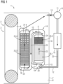
- the drawing shows an embodiment of the electrical device 1 according to the invention, which is designed as a transformer.
- the transformer 1 has an active part 2, which is formed from a core 3, a low-voltage winding 4 and a high-voltage winding 5.
- the low-voltage winding 4 and the high-voltage winding 5 are arranged concentrically to a leg 6 of the core 3, wherein in the Figure 1 only one side of the windings is shown.
- both the low-voltage winding and the high-voltage winding are circumferentially closed partial windings, i.e. they run in a ring shape around the leg 6.
- the active part 2 is arranged within a vessel 7 which is filled with an insulating fluid 8, in the embodiment shown a vegetable ester.
- a cooling device 9 is attached to the vessel 7, which has a cooling register 10, a circulation pump 11, a supply line 12 and has a return line 13.
- the transformer 1 is intended for connection to a high-voltage network, so that when the transformer is in operation, the high-voltage winding 5 is at a high-voltage potential, i.e. is subjected to a voltage of over 50 kV.
- a barrier system 14 is used to control the electrical field that occurs, which almost completely encloses both the low-voltage winding 4 and the high-voltage winding 5 with one of its insulation sections.
- the barrier system 14 is made at least partially from pressboard or another cellulose-based material and has curved sections 15 and cylindrical sections 16, which are arranged in such a way that the high-voltage winding 5 and the low-voltage winding 4 are each arranged in an encapsulation space 17 and 18, which are fluidically connected to one another.
- the encapsulation spaces 17, 18 are not completely fluid-tight.
- Some insulating fluid 8 can therefore also escape from the inside to the outside of the barrier system 14 above the high-voltage winding 5. However, these "unintentionally" escaping fluid quantities can be neglected with regard to cooling.
- the main part of the flow of the insulating fluid is guided through the barrier system 14.
- the barrier system 14 forms an inlet opening 19 below the high-voltage winding 5, through which the cooled insulating fluid emerging from the supply line 12 of the cooling device 9 enters the barrier system 14.
- the barrier system 14 also forms an outlet opening 21, which in the example shown is arranged above the low-voltage winding 4.
- the encapsulation spaces 17 and 18 are also hydraulically coupled to one another.
- the circulation pump 11 ensures that the insulating fluid 8 flows through the active part 2 and the vessel 7 in the direction indicated by flow arrows 23.
- Each partial winding 4 and 5 has shield rings 24 which are arranged at their upper and lower ends for field control.
- the insulating fluid 8 i.e. the ester
- the circulation pump 11 By circulating by means of the circulation pump 11, the insulating fluid 8, i.e. the ester, is guided over the cooling register 10 and cooled, whereby cooled insulating fluid 8 emerging from the outlet opening 20 of the supply line 12 enters the barrier system 14 through the inlet opening 19. There, the insulating fluid 8 is deflected several times, i.e. guided in a meandering manner, until it reaches the lower end of the high-voltage winding 5, in which cooling channels are formed. In these cooling channels (not shown in the figure), the heat loss of the high-voltage winding 5 is transferred to the insulating fluid 8 flowing through the cooling channels. This results in a continuous heating of the insulating fluid 8.
- the high-voltage winding 5 forms two temperature ranges 25.1 and 25.2, which in Figure 1 are indicated by a different pattern.
- the winding 5 is equipped with different insulating materials, which are assigned, for example, to different thermal classes.
- the gradually warming insulating fluid 8 enters the encapsulation space 18 of the low-voltage winding 4 from the encapsulation space 17 of the high-voltage winding 5.
- the barrier system 14 guides the insulating fluid 8 over the low-voltage winding 4, which also has cooling channels and temperature areas 25.3 and 25.4 with different insulating materials.
- the insulating fluid 8, which has been heated again here enters the interior of the vessel through the outlet opening 21. From there, the insulating fluid 8 is fed back to the cooling register 10 via the return line 13 and the circulation pump 11. The cooling cycle begins again.
- the encapsulation chamber temperature i.e. the temperature of the winding 5 and the insulating fluid 8 is on average lower in the temperature range 25.1 than in the temperature range 25.2 and especially in the temperature ranges 25.3 and 25.4.
- the grading of the thermal performance of the insulating materials can also be carried out within the thermal classes according to EN 60085. There are a variety of possibilities here, for example grading in temperature steps of less than 10 Kelvin is also possible.
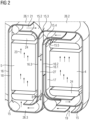
- Fig. 2 shows a simplified embodiment of the electrical device 1 according to the invention, wherein the barrier system 14 is particularly clearly visible.
- the barrier system 14 is designed in such a way that it can be used to guide and deflect the flow of the insulating fluid 8.
- the barrier system 14 again has cylindrical sections 16, 16.1, 16.2, 16.3, disk-shaped Sections 26.1, 26.2, 26.3 and curved sections 15, 15.1, 15.2, 15.3 and 15.4, the latter also referred to as angle rings or caps.
- the barrier system 14 is designed in such a way that encapsulated winding spaces are formed, which are referred to here as encapsulation spaces 17, 28.
- encapsulation spaces 17, 28 the usually present, outer horizontal, disk-shaped barriers that delimit a flow channel for the insulating fluid are replaced by closed disks 26.2, 26.3, so that the inflow and outflow of the insulating fluid 8 into the encapsulation spaces 17 and 18 takes place in a controlled manner via the inlet 19 and outlet opening 21.
- the encapsulation spaces 17 and 18 are fluidically connected to one another by using the gap between the cylindrical sections 16.2 and 16.3 as a return flow channel 27 for the insulating fluid.
- the inlet opening 19 is formed in the so-called winding substructure.
- the outlet opening 21 is located in the disk-shaped section 26.1.
- the gap between the curved sections 15.3 and 15.4 is used to deflect or, in other words, reverse the direction of the flow 23 of the insulating fluid 8.
- the construction of closed barrier surfaces as perpendicular to the field direction as possible is preferable.
- the curved barriers should therefore also follow the course of the equipotential lines.
- the resulting largely parallel arrangement of the curved sections 15, 15.2 also facilitates use as a flow channel 27 for redirecting the flow of the insulating fluid 8, so that only minor fluidic changes are necessary.
- additional flow-guiding barriers are used. and curved barriers 15.3 sealing the winding space to the outside are inserted.
- an additional curved barrier 15.3 which serves to redirect the flow of the insulating fluid, results in an overlay of several solid insulations at the interface between the cylindrical and curved barrier sections.
- shouldered 15.2 and unshouldered angle rings with a small wall thickness 15.3 are combined at the interface between the curved barriers and the cylindrical barriers and arranged opposite one another on the cylindrical section 16.3.
- Fig. 3 shows an embodiment in which only one of the encapsulation spaces 17, 18 has a partial winding with several temperature ranges 25.1 and 25.2.
- the thermal class of the conductor insulation 26 increases from encapsulation space 17 to encapsulation space 18 and in the latter again from temperature range 25.1 to temperature range 25.2.
- the transition of the temperature ranges takes place after reaching a winding height H1.
- the oil gaps of the insulation structure are divided into narrower vertical channels 27 and horizontal channels 28 by the barrier system 14.
- These channels 27, 28 are used according to the invention to guide the insulating fluid 8 to the partial winding 4 downstream in the direction of flow 23.
- several of these channels 27, 28 extend parallel to one another in order to achieve the cross-section required for the flow of the insulating fluid 8.
- the cross-section or more precisely the cross-sectional area and the number of interconnected vertical 27 and horizontal 28 channels can differ from one another within the scope of the invention.
- the channels 29 that are not used as flow channels used completely or partially closed at their lower end by inserts 30 made of insulating material.
- insulating fluid 8 flows from an outer vertical channel through several horizontal channels into a second outer channel, where the flow direction of the insulating fluid 8 is diverted so that the insulating fluid 8 flows in the opposite direction as it continues, so that it changes the flow direction several times along the height of the winding.
- inventive design of the barrier system 14 and insulation can be applied analogously to all other winding types.
- the partial windings are equipped with thermal sensors 31 at so-called hot spots in their respective temperature ranges 5, 25.1 and 25.2.
- the sensors 31 are connected to a control unit not shown in the figure.
- a further sensor 32 for measuring the maximum temperature of the insulating fluid 8 is arranged at the outlet opening 21 of the last thermally series-connected partial winding 4. If required, the maximum temperature of the insulating fluid 8 in the upstream partial winding 5 can also be monitored via the sensor 33.
- Fig. 4 shows an embodiment in which the core 3 is included in the cooling circuit. This is advantageous if a large temperature spread of the insulating fluid 8 is provided.
- the design of the core 3 for higher temperatures requires only a very small amount of effort, since no molded parts are required and an electric field stress does not have to be taken into account. Therefore, the core 3 is arranged at the end of the fluidic series connection of the components of the electrical device 1 to be cooled.
- the windings are successively 5 and 4 and then the core 3 are flowed through by the insulating fluid 8.
- the cooling channels of the partial windings 4, 5 and cooling channels 34 of the core 3 are connected in series in terms of thermal and fluid technology.
- the barriers are designed such that the main flow of the insulating fluid 8 within the encapsulation spaces 17 and 18 and in the core 3 is directed from bottom to top, i.e. is aligned with the inherent movement of the insulating fluid 8 generated by heating.
- the return of the insulating fluid 8 takes place in the vertical channels 27 between the barriers of the insulation arrangement, which are referred to here as insulation sections of the barrier system 14.
- the vertical sections 16 of the barrier system 14, which delimit channels 27 with opposite flow directions, are provided with additional thermal insulation 35 in areas with a high temperature difference of the insulating fluid 8. In a simple case, this can be done by increasing the wall thickness. In the areas close to the reversal of direction of the insulating fluid 8, the temperature difference is small. No measures are therefore required there.
Landscapes
- Engineering & Computer Science (AREA)
- Power Engineering (AREA)
- Transformer Cooling (AREA)
- Coils Of Transformers For General Uses (AREA)
Applications Claiming Priority (2)
| Application Number | Priority Date | Filing Date | Title |
|---|---|---|---|
| DE102016219378.3A DE102016219378A1 (de) | 2016-10-06 | 2016-10-06 | Elektrisches Gerät mit unterschiedlich stark gekühlten Kapselungsräumen |
| PCT/EP2017/073248 WO2018065188A1 (de) | 2016-10-06 | 2017-09-15 | Elektrisches gerät mit unterschiedlich stark gekühlten kapselungsräumen |
Publications (3)
| Publication Number | Publication Date |
|---|---|
| EP3494583A1 EP3494583A1 (de) | 2019-06-12 |
| EP3494583C0 EP3494583C0 (de) | 2024-12-04 |
| EP3494583B1 true EP3494583B1 (de) | 2024-12-04 |
Family
ID=59859096
Family Applications (1)
| Application Number | Title | Priority Date | Filing Date |
|---|---|---|---|
| EP17767832.3A Active EP3494583B1 (de) | 2016-10-06 | 2017-09-15 | Elektrisches gerät mit unterschiedlich stark gekühlten kapselungsräumen |
Country Status (5)
| Country | Link |
|---|---|
| US (1) | US11322289B2 (pl) |
| EP (1) | EP3494583B1 (pl) |
| DE (1) | DE102016219378A1 (pl) |
| PL (1) | PL3494583T3 (pl) |
| WO (1) | WO2018065188A1 (pl) |
Families Citing this family (7)
| Publication number | Priority date | Publication date | Assignee | Title |
|---|---|---|---|---|
| WO2019133972A1 (en) * | 2017-12-30 | 2019-07-04 | Abb Schweiz Ag | System for sensor utilization in a transformer cooling circuit |
| JP7080796B2 (ja) * | 2018-10-31 | 2022-06-06 | 株式会社東芝 | 電流導入端子構造及び電磁石装置 |
| EP3767651A1 (de) * | 2019-07-17 | 2021-01-20 | Siemens Aktiengesellschaft | Verfahren zum betreiben eines kühlsystems eines transformators |
| CN110428951B (zh) * | 2019-08-08 | 2021-06-04 | 李辛阳 | 一种基于温度变化的变压器散热设备 |
| CN112863813B (zh) * | 2021-02-04 | 2021-11-23 | 台州市康新电容器有限公司 | 一种变压器防水外罩 |
| CN114898992A (zh) * | 2022-04-29 | 2022-08-12 | 武汉大学 | 一种66kV高电压等级、10MVA大容量的海上风电干式变压器 |
| US20240326651A1 (en) * | 2023-03-30 | 2024-10-03 | InductEV, Inc. | System and method for thermal management of an inductive wireless power charger |
Citations (1)
| Publication number | Priority date | Publication date | Assignee | Title |
|---|---|---|---|---|
| DE19701269A1 (de) * | 1997-01-16 | 1998-07-23 | Ask Antriebs Steuerungs Und In | Transformator mit Flüssigkeitskühlung |
Family Cites Families (13)
| Publication number | Priority date | Publication date | Assignee | Title |
|---|---|---|---|---|
| US3144770A (en) * | 1961-01-30 | 1964-08-18 | Gen Electric | Means for determining an internal condition in electrical apparatus |
| DE2016508A1 (de) * | 1970-04-07 | 1972-10-19 | Skoda Np | Wicklung einer nichtrotierenden elektromagnetischen Maschine, besonders eines Transformators |
| DE2738398C3 (de) * | 1977-08-25 | 1981-08-13 | Transformatoren Union Ag, 7000 Stuttgart | Gestell zur Halterung und Pressung von Wicklungen in flüssigkeitsgekühlten Großtransformatoren |
| DE2364438B2 (de) | 1973-12-24 | 1979-03-29 | Henkel Kgaa, 4000 Duesseldorf | Verwendung von wäßrigen Klebstofflösungen auf Basis von Polyvinylalkohol |
| US3902146A (en) * | 1974-11-27 | 1975-08-26 | Gen Electric | Transformer with improved liquid cooled disc winding |
| JPS5296313A (en) * | 1976-02-09 | 1977-08-12 | Hitachi Ltd | Oil-filled transformer |
| JPS5442620A (en) * | 1977-09-12 | 1979-04-04 | Hitachi Ltd | Transformer winding |
| JPS5790921A (en) * | 1980-11-27 | 1982-06-05 | Toshiba Corp | Oil immersed transformer |
| JPS60246608A (ja) * | 1984-05-22 | 1985-12-06 | Kitashiba Denki Kk | 油入機器巻線の冷却方法 |
| JPS61150309A (ja) * | 1984-12-25 | 1986-07-09 | Toshiba Corp | 送油式変圧器巻線 |
| JP2853505B2 (ja) * | 1993-03-19 | 1999-02-03 | 三菱電機株式会社 | 静止誘導機器 |
| US6494617B1 (en) * | 1999-04-30 | 2002-12-17 | General Electric Company | Status detection apparatus and method for fluid-filled electrical equipment |
| US6401518B1 (en) * | 1999-07-29 | 2002-06-11 | General Electric Company | Fluid filled electrical device with diagnostic sensor located in fluid circulation flow path |
-
2016
- 2016-10-06 DE DE102016219378.3A patent/DE102016219378A1/de not_active Ceased
-
2017
- 2017-09-15 PL PL17767832.3T patent/PL3494583T3/pl unknown
- 2017-09-15 WO PCT/EP2017/073248 patent/WO2018065188A1/de not_active Ceased
- 2017-09-15 EP EP17767832.3A patent/EP3494583B1/de active Active
- 2017-09-15 US US16/340,266 patent/US11322289B2/en active Active
Patent Citations (1)
| Publication number | Priority date | Publication date | Assignee | Title |
|---|---|---|---|---|
| DE19701269A1 (de) * | 1997-01-16 | 1998-07-23 | Ask Antriebs Steuerungs Und In | Transformator mit Flüssigkeitskühlung |
Also Published As
| Publication number | Publication date |
|---|---|
| DE102016219378A1 (de) | 2018-04-12 |
| US20190259521A1 (en) | 2019-08-22 |
| EP3494583C0 (de) | 2024-12-04 |
| WO2018065188A1 (de) | 2018-04-12 |
| US11322289B2 (en) | 2022-05-03 |
| PL3494583T3 (pl) | 2025-04-07 |
| EP3494583A1 (de) | 2019-06-12 |
Similar Documents
| Publication | Publication Date | Title |
|---|---|---|
| EP3494583B1 (de) | Elektrisches gerät mit unterschiedlich stark gekühlten kapselungsräumen | |
| DE102015216055B4 (de) | Kühlsystem für eine elektrische Maschine | |
| DE2260746A1 (de) | Kuehlsystem fuer kabelendverschluesse | |
| DE102017222635A1 (de) | Stator und Elektromaschine mit Kühlsystem | |
| WO2008083838A1 (de) | Halbleiterbaugruppe zum anschluss an eine transformatorwicklung und transformatoranordnung | |
| EP3494584B1 (de) | Elektrisches gerät mit mehreren kühleinheiten | |
| WO2021099190A1 (de) | Kühlsystem und bauteil für eine elektrische maschine mit hohlleiterkühlung | |
| DE102016200742B3 (de) | Eine Kühlflüssigkeit enthaltendes Gehäuse eines elektrischen Gerätes | |
| DE3336842C2 (pl) | ||
| AT522500A1 (de) | Spiralwärmetauscher | |
| CH701383B1 (de) | Ablenkvorrichtung für Kühlfluide und deren Verwendung in einem Leistungsgenerator. | |
| WO2011026603A1 (de) | Trockentransformator | |
| DE19912280C1 (de) | Transformator und Verfahren zur Kühlung eines Transformators | |
| DE112022007711T5 (de) | Stator einer elektrischen Maschine mit inneren Kühlkanälen | |
| DE102020212463B4 (de) | Flüssigkeitsgekühlter Bremswiderstand mit Turbulator | |
| EP1903583B1 (de) | Hochstrom-Trafodurchführung | |
| WO2017097351A1 (de) | Hochenergie-stossstrombegrenzer | |
| EP2511919A1 (de) | Trockentransformatorheizung | |
| EP4093153B1 (de) | Vorrichtung zur induktiven erwärmung von metallgut | |
| DE2738398C3 (de) | Gestell zur Halterung und Pressung von Wicklungen in flüssigkeitsgekühlten Großtransformatoren | |
| WO2024200354A1 (de) | Elektrische kontaktierung in einem kühlbaren widerstand | |
| DE3837198A1 (de) | Elektroerhitzer zur thermischen behandlung von ein- oder mehrphasigen fluiden mit durch elektrischer widerstandsheizung direkt beheiztem rohr | |
| DE202021004265U1 (de) | Vorrichtung zur induktiven Erwärmung von Metallgut | |
| DE102020212467A1 (de) | Flüssigkeitsgekühlter Bremswiderstand | |
| DE2208427A1 (de) | Hochspannungs-Stromwandler mit Thermosyphon-Kühlung |
Legal Events
| Date | Code | Title | Description |
|---|---|---|---|
| STAA | Information on the status of an ep patent application or granted ep patent |
Free format text: STATUS: UNKNOWN |
|
| STAA | Information on the status of an ep patent application or granted ep patent |
Free format text: STATUS: THE INTERNATIONAL PUBLICATION HAS BEEN MADE |
|
| PUAI | Public reference made under article 153(3) epc to a published international application that has entered the european phase |
Free format text: ORIGINAL CODE: 0009012 |
|
| STAA | Information on the status of an ep patent application or granted ep patent |
Free format text: STATUS: REQUEST FOR EXAMINATION WAS MADE |
|
| 17P | Request for examination filed |
Effective date: 20190307 |
|
| AK | Designated contracting states |
Kind code of ref document: A1 Designated state(s): AL AT BE BG CH CY CZ DE DK EE ES FI FR GB GR HR HU IE IS IT LI LT LU LV MC MK MT NL NO PL PT RO RS SE SI SK SM TR |
|
| AX | Request for extension of the european patent |
Extension state: BA ME |
|
| DAV | Request for validation of the european patent (deleted) | ||
| DAX | Request for extension of the european patent (deleted) | ||
| RAP1 | Party data changed (applicant data changed or rights of an application transferred) |
Owner name: SIEMENS ENERGY GLOBAL GMBH & CO. KG |
|
| STAA | Information on the status of an ep patent application or granted ep patent |
Free format text: STATUS: EXAMINATION IS IN PROGRESS |
|
| 17Q | First examination report despatched |
Effective date: 20210929 |
|
| GRAP | Despatch of communication of intention to grant a patent |
Free format text: ORIGINAL CODE: EPIDOSNIGR1 |
|
| STAA | Information on the status of an ep patent application or granted ep patent |
Free format text: STATUS: GRANT OF PATENT IS INTENDED |
|
| INTG | Intention to grant announced |
Effective date: 20240709 |
|
| GRAS | Grant fee paid |
Free format text: ORIGINAL CODE: EPIDOSNIGR3 |
|
| GRAA | (expected) grant |
Free format text: ORIGINAL CODE: 0009210 |
|
| STAA | Information on the status of an ep patent application or granted ep patent |
Free format text: STATUS: THE PATENT HAS BEEN GRANTED |
|
| AK | Designated contracting states |
Kind code of ref document: B1 Designated state(s): AL AT BE BG CH CY CZ DE DK EE ES FI FR GB GR HR HU IE IS IT LI LT LU LV MC MK MT NL NO PL PT RO RS SE SI SK SM TR |
|
| REG | Reference to a national code |
Ref country code: GB Ref legal event code: FG4D Free format text: NOT ENGLISH |
|
| REG | Reference to a national code |
Ref country code: CH Ref legal event code: EP |
|
| REG | Reference to a national code |
Ref country code: DE Ref legal event code: R096 Ref document number: 502017016587 Country of ref document: DE |
|
| REG | Reference to a national code |
Ref country code: IE Ref legal event code: FG4D Free format text: LANGUAGE OF EP DOCUMENT: GERMAN |
|
| U01 | Request for unitary effect filed |
Effective date: 20241204 |
|
| U07 | Unitary effect registered |
Designated state(s): AT BE BG DE DK EE FI FR IT LT LU LV MT NL PT RO SE SI Effective date: 20241210 |
|
| PG25 | Lapsed in a contracting state [announced via postgrant information from national office to epo] |
Ref country code: HR Free format text: LAPSE BECAUSE OF FAILURE TO SUBMIT A TRANSLATION OF THE DESCRIPTION OR TO PAY THE FEE WITHIN THE PRESCRIBED TIME-LIMIT Effective date: 20241204 |
|
| PG25 | Lapsed in a contracting state [announced via postgrant information from national office to epo] |
Ref country code: ES Free format text: LAPSE BECAUSE OF FAILURE TO SUBMIT A TRANSLATION OF THE DESCRIPTION OR TO PAY THE FEE WITHIN THE PRESCRIBED TIME-LIMIT Effective date: 20241204 |
|
| PG25 | Lapsed in a contracting state [announced via postgrant information from national office to epo] |
Ref country code: NO Free format text: LAPSE BECAUSE OF FAILURE TO SUBMIT A TRANSLATION OF THE DESCRIPTION OR TO PAY THE FEE WITHIN THE PRESCRIBED TIME-LIMIT Effective date: 20250304 |
|
| PG25 | Lapsed in a contracting state [announced via postgrant information from national office to epo] |
Ref country code: GR Free format text: LAPSE BECAUSE OF FAILURE TO SUBMIT A TRANSLATION OF THE DESCRIPTION OR TO PAY THE FEE WITHIN THE PRESCRIBED TIME-LIMIT Effective date: 20250305 |
|
| PG25 | Lapsed in a contracting state [announced via postgrant information from national office to epo] |
Ref country code: RS Free format text: LAPSE BECAUSE OF FAILURE TO SUBMIT A TRANSLATION OF THE DESCRIPTION OR TO PAY THE FEE WITHIN THE PRESCRIBED TIME-LIMIT Effective date: 20250304 |
|
| PG25 | Lapsed in a contracting state [announced via postgrant information from national office to epo] |
Ref country code: SM Free format text: LAPSE BECAUSE OF FAILURE TO SUBMIT A TRANSLATION OF THE DESCRIPTION OR TO PAY THE FEE WITHIN THE PRESCRIBED TIME-LIMIT Effective date: 20241204 |
|
| PG25 | Lapsed in a contracting state [announced via postgrant information from national office to epo] |
Ref country code: IS Free format text: LAPSE BECAUSE OF FAILURE TO SUBMIT A TRANSLATION OF THE DESCRIPTION OR TO PAY THE FEE WITHIN THE PRESCRIBED TIME-LIMIT Effective date: 20250404 |
|
| PG25 | Lapsed in a contracting state [announced via postgrant information from national office to epo] |
Ref country code: SK Free format text: LAPSE BECAUSE OF FAILURE TO SUBMIT A TRANSLATION OF THE DESCRIPTION OR TO PAY THE FEE WITHIN THE PRESCRIBED TIME-LIMIT Effective date: 20241204 |
|
| PG25 | Lapsed in a contracting state [announced via postgrant information from national office to epo] |
Ref country code: CZ Free format text: LAPSE BECAUSE OF FAILURE TO SUBMIT A TRANSLATION OF THE DESCRIPTION OR TO PAY THE FEE WITHIN THE PRESCRIBED TIME-LIMIT Effective date: 20241204 |
|
| PLBE | No opposition filed within time limit |
Free format text: ORIGINAL CODE: 0009261 |
|
| STAA | Information on the status of an ep patent application or granted ep patent |
Free format text: STATUS: NO OPPOSITION FILED WITHIN TIME LIMIT |
|
| PGFP | Annual fee paid to national office [announced via postgrant information from national office to epo] |
Ref country code: GB Payment date: 20250923 Year of fee payment: 9 |
|
| U20 | Renewal fee for the european patent with unitary effect paid |
Year of fee payment: 9 Effective date: 20250925 |
|
| 26N | No opposition filed |
Effective date: 20250905 |
|
| PGFP | Annual fee paid to national office [announced via postgrant information from national office to epo] |
Ref country code: PL Payment date: 20250820 Year of fee payment: 9 |