EP3492753B1 - Hydraulic drive device for working vehicle - Google Patents
Hydraulic drive device for working vehicle Download PDFInfo
- Publication number
- EP3492753B1 EP3492753B1 EP18775063.3A EP18775063A EP3492753B1 EP 3492753 B1 EP3492753 B1 EP 3492753B1 EP 18775063 A EP18775063 A EP 18775063A EP 3492753 B1 EP3492753 B1 EP 3492753B1
- Authority
- EP
- European Patent Office
- Prior art keywords
- pressure
- flow passage
- sub
- valve
- pump
- Prior art date
- Legal status (The legal status is an assumption and is not a legal conclusion. Google has not performed a legal analysis and makes no representation as to the accuracy of the status listed.)
- Active
Links
Images








Classifications
-
- E—FIXED CONSTRUCTIONS
- E02—HYDRAULIC ENGINEERING; FOUNDATIONS; SOIL SHIFTING
- E02F—DREDGING; SOIL-SHIFTING
- E02F9/00—Component parts of dredgers or soil-shifting machines, not restricted to one of the kinds covered by groups E02F3/00 - E02F7/00
- E02F9/20—Drives; Control devices
- E02F9/22—Hydraulic or pneumatic drives
- E02F9/2203—Arrangements for controlling the attitude of actuators, e.g. speed, floating function
- E02F9/2214—Arrangements for controlling the attitude of actuators, e.g. speed, floating function for reducing the shock generated at the stroke end
-
- E—FIXED CONSTRUCTIONS
- E02—HYDRAULIC ENGINEERING; FOUNDATIONS; SOIL SHIFTING
- E02F—DREDGING; SOIL-SHIFTING
- E02F9/00—Component parts of dredgers or soil-shifting machines, not restricted to one of the kinds covered by groups E02F3/00 - E02F7/00
- E02F9/20—Drives; Control devices
- E02F9/22—Hydraulic or pneumatic drives
- E02F9/2221—Control of flow rate; Load sensing arrangements
- E02F9/2225—Control of flow rate; Load sensing arrangements using pressure-compensating valves
- E02F9/2228—Control of flow rate; Load sensing arrangements using pressure-compensating valves including an electronic controller
-
- E—FIXED CONSTRUCTIONS
- E02—HYDRAULIC ENGINEERING; FOUNDATIONS; SOIL SHIFTING
- E02F—DREDGING; SOIL-SHIFTING
- E02F9/00—Component parts of dredgers or soil-shifting machines, not restricted to one of the kinds covered by groups E02F3/00 - E02F7/00
- E02F9/20—Drives; Control devices
- E02F9/22—Hydraulic or pneumatic drives
-
- E—FIXED CONSTRUCTIONS
- E02—HYDRAULIC ENGINEERING; FOUNDATIONS; SOIL SHIFTING
- E02F—DREDGING; SOIL-SHIFTING
- E02F9/00—Component parts of dredgers or soil-shifting machines, not restricted to one of the kinds covered by groups E02F3/00 - E02F7/00
- E02F9/20—Drives; Control devices
- E02F9/22—Hydraulic or pneumatic drives
- E02F9/2264—Arrangements or adaptations of elements for hydraulic drives
- E02F9/2267—Valves or distributors
-
- E—FIXED CONSTRUCTIONS
- E02—HYDRAULIC ENGINEERING; FOUNDATIONS; SOIL SHIFTING
- E02F—DREDGING; SOIL-SHIFTING
- E02F9/00—Component parts of dredgers or soil-shifting machines, not restricted to one of the kinds covered by groups E02F3/00 - E02F7/00
- E02F9/20—Drives; Control devices
- E02F9/22—Hydraulic or pneumatic drives
- E02F9/2278—Hydraulic circuits
- E02F9/2292—Systems with two or more pumps
-
- E—FIXED CONSTRUCTIONS
- E02—HYDRAULIC ENGINEERING; FOUNDATIONS; SOIL SHIFTING
- E02F—DREDGING; SOIL-SHIFTING
- E02F9/00—Component parts of dredgers or soil-shifting machines, not restricted to one of the kinds covered by groups E02F3/00 - E02F7/00
- E02F9/20—Drives; Control devices
- E02F9/22—Hydraulic or pneumatic drives
- E02F9/2278—Hydraulic circuits
- E02F9/2296—Systems with a variable displacement pump
-
- F—MECHANICAL ENGINEERING; LIGHTING; HEATING; WEAPONS; BLASTING
- F15—FLUID-PRESSURE ACTUATORS; HYDRAULICS OR PNEUMATICS IN GENERAL
- F15B—SYSTEMS ACTING BY MEANS OF FLUIDS IN GENERAL; FLUID-PRESSURE ACTUATORS, e.g. SERVOMOTORS; DETAILS OF FLUID-PRESSURE SYSTEMS, NOT OTHERWISE PROVIDED FOR
- F15B11/00—Servomotor systems without provision for follow-up action; Circuits therefor
- F15B11/02—Systems essentially incorporating special features for controlling the speed or actuating force of an output member
-
- F—MECHANICAL ENGINEERING; LIGHTING; HEATING; WEAPONS; BLASTING
- F15—FLUID-PRESSURE ACTUATORS; HYDRAULICS OR PNEUMATICS IN GENERAL
- F15B—SYSTEMS ACTING BY MEANS OF FLUIDS IN GENERAL; FLUID-PRESSURE ACTUATORS, e.g. SERVOMOTORS; DETAILS OF FLUID-PRESSURE SYSTEMS, NOT OTHERWISE PROVIDED FOR
- F15B11/00—Servomotor systems without provision for follow-up action; Circuits therefor
- F15B11/02—Systems essentially incorporating special features for controlling the speed or actuating force of an output member
- F15B11/028—Systems essentially incorporating special features for controlling the speed or actuating force of an output member for controlling the actuating force
-
- F—MECHANICAL ENGINEERING; LIGHTING; HEATING; WEAPONS; BLASTING
- F15—FLUID-PRESSURE ACTUATORS; HYDRAULICS OR PNEUMATICS IN GENERAL
- F15B—SYSTEMS ACTING BY MEANS OF FLUIDS IN GENERAL; FLUID-PRESSURE ACTUATORS, e.g. SERVOMOTORS; DETAILS OF FLUID-PRESSURE SYSTEMS, NOT OTHERWISE PROVIDED FOR
- F15B11/00—Servomotor systems without provision for follow-up action; Circuits therefor
- F15B11/02—Systems essentially incorporating special features for controlling the speed or actuating force of an output member
- F15B11/04—Systems essentially incorporating special features for controlling the speed or actuating force of an output member for controlling the speed
- F15B11/042—Systems essentially incorporating special features for controlling the speed or actuating force of an output member for controlling the speed by means in the feed line, i.e. "meter in"
- F15B11/0426—Systems essentially incorporating special features for controlling the speed or actuating force of an output member for controlling the speed by means in the feed line, i.e. "meter in" by controlling the number of pumps or parallel valves switched on
-
- F—MECHANICAL ENGINEERING; LIGHTING; HEATING; WEAPONS; BLASTING
- F15—FLUID-PRESSURE ACTUATORS; HYDRAULICS OR PNEUMATICS IN GENERAL
- F15B—SYSTEMS ACTING BY MEANS OF FLUIDS IN GENERAL; FLUID-PRESSURE ACTUATORS, e.g. SERVOMOTORS; DETAILS OF FLUID-PRESSURE SYSTEMS, NOT OTHERWISE PROVIDED FOR
- F15B11/00—Servomotor systems without provision for follow-up action; Circuits therefor
- F15B11/02—Systems essentially incorporating special features for controlling the speed or actuating force of an output member
- F15B11/04—Systems essentially incorporating special features for controlling the speed or actuating force of an output member for controlling the speed
- F15B11/046—Systems essentially incorporating special features for controlling the speed or actuating force of an output member for controlling the speed depending on the position of the working member
- F15B11/048—Systems essentially incorporating special features for controlling the speed or actuating force of an output member for controlling the speed depending on the position of the working member with deceleration control
-
- F—MECHANICAL ENGINEERING; LIGHTING; HEATING; WEAPONS; BLASTING
- F15—FLUID-PRESSURE ACTUATORS; HYDRAULICS OR PNEUMATICS IN GENERAL
- F15B—SYSTEMS ACTING BY MEANS OF FLUIDS IN GENERAL; FLUID-PRESSURE ACTUATORS, e.g. SERVOMOTORS; DETAILS OF FLUID-PRESSURE SYSTEMS, NOT OTHERWISE PROVIDED FOR
- F15B11/00—Servomotor systems without provision for follow-up action; Circuits therefor
- F15B11/08—Servomotor systems without provision for follow-up action; Circuits therefor with only one servomotor
- F15B11/10—Servomotor systems without provision for follow-up action; Circuits therefor with only one servomotor in which the servomotor position is a function of the pressure also pressure regulators as operating means for such systems, the device itself may be a position indicating system
-
- E—FIXED CONSTRUCTIONS
- E02—HYDRAULIC ENGINEERING; FOUNDATIONS; SOIL SHIFTING
- E02F—DREDGING; SOIL-SHIFTING
- E02F9/00—Component parts of dredgers or soil-shifting machines, not restricted to one of the kinds covered by groups E02F3/00 - E02F7/00
- E02F9/20—Drives; Control devices
- E02F9/22—Hydraulic or pneumatic drives
- E02F9/2278—Hydraulic circuits
- E02F9/2285—Pilot-operated systems
-
- F—MECHANICAL ENGINEERING; LIGHTING; HEATING; WEAPONS; BLASTING
- F15—FLUID-PRESSURE ACTUATORS; HYDRAULICS OR PNEUMATICS IN GENERAL
- F15B—SYSTEMS ACTING BY MEANS OF FLUIDS IN GENERAL; FLUID-PRESSURE ACTUATORS, e.g. SERVOMOTORS; DETAILS OF FLUID-PRESSURE SYSTEMS, NOT OTHERWISE PROVIDED FOR
- F15B2211/00—Circuits for servomotor systems
- F15B2211/20—Fluid pressure source, e.g. accumulator or variable axial piston pump
- F15B2211/205—Systems with pumps
- F15B2211/2053—Type of pump
- F15B2211/20538—Type of pump constant capacity
-
- F—MECHANICAL ENGINEERING; LIGHTING; HEATING; WEAPONS; BLASTING
- F15—FLUID-PRESSURE ACTUATORS; HYDRAULICS OR PNEUMATICS IN GENERAL
- F15B—SYSTEMS ACTING BY MEANS OF FLUIDS IN GENERAL; FLUID-PRESSURE ACTUATORS, e.g. SERVOMOTORS; DETAILS OF FLUID-PRESSURE SYSTEMS, NOT OTHERWISE PROVIDED FOR
- F15B2211/00—Circuits for servomotor systems
- F15B2211/20—Fluid pressure source, e.g. accumulator or variable axial piston pump
- F15B2211/205—Systems with pumps
- F15B2211/2053—Type of pump
- F15B2211/20546—Type of pump variable capacity
-
- F—MECHANICAL ENGINEERING; LIGHTING; HEATING; WEAPONS; BLASTING
- F15—FLUID-PRESSURE ACTUATORS; HYDRAULICS OR PNEUMATICS IN GENERAL
- F15B—SYSTEMS ACTING BY MEANS OF FLUIDS IN GENERAL; FLUID-PRESSURE ACTUATORS, e.g. SERVOMOTORS; DETAILS OF FLUID-PRESSURE SYSTEMS, NOT OTHERWISE PROVIDED FOR
- F15B2211/00—Circuits for servomotor systems
- F15B2211/20—Fluid pressure source, e.g. accumulator or variable axial piston pump
- F15B2211/205—Systems with pumps
- F15B2211/20576—Systems with pumps with multiple pumps
-
- F—MECHANICAL ENGINEERING; LIGHTING; HEATING; WEAPONS; BLASTING
- F15—FLUID-PRESSURE ACTUATORS; HYDRAULICS OR PNEUMATICS IN GENERAL
- F15B—SYSTEMS ACTING BY MEANS OF FLUIDS IN GENERAL; FLUID-PRESSURE ACTUATORS, e.g. SERVOMOTORS; DETAILS OF FLUID-PRESSURE SYSTEMS, NOT OTHERWISE PROVIDED FOR
- F15B2211/00—Circuits for servomotor systems
- F15B2211/20—Fluid pressure source, e.g. accumulator or variable axial piston pump
- F15B2211/205—Systems with pumps
- F15B2211/20576—Systems with pumps with multiple pumps
- F15B2211/20584—Combinations of pumps with high and low capacity
-
- F—MECHANICAL ENGINEERING; LIGHTING; HEATING; WEAPONS; BLASTING
- F15—FLUID-PRESSURE ACTUATORS; HYDRAULICS OR PNEUMATICS IN GENERAL
- F15B—SYSTEMS ACTING BY MEANS OF FLUIDS IN GENERAL; FLUID-PRESSURE ACTUATORS, e.g. SERVOMOTORS; DETAILS OF FLUID-PRESSURE SYSTEMS, NOT OTHERWISE PROVIDED FOR
- F15B2211/00—Circuits for servomotor systems
- F15B2211/30—Directional control
- F15B2211/305—Directional control characterised by the type of valves
- F15B2211/30525—Directional control valves, e.g. 4/3-directional control valve
-
- F—MECHANICAL ENGINEERING; LIGHTING; HEATING; WEAPONS; BLASTING
- F15—FLUID-PRESSURE ACTUATORS; HYDRAULICS OR PNEUMATICS IN GENERAL
- F15B—SYSTEMS ACTING BY MEANS OF FLUIDS IN GENERAL; FLUID-PRESSURE ACTUATORS, e.g. SERVOMOTORS; DETAILS OF FLUID-PRESSURE SYSTEMS, NOT OTHERWISE PROVIDED FOR
- F15B2211/00—Circuits for servomotor systems
- F15B2211/30—Directional control
- F15B2211/32—Directional control characterised by the type of actuation
- F15B2211/329—Directional control characterised by the type of actuation actuated by fluid pressure
-
- F—MECHANICAL ENGINEERING; LIGHTING; HEATING; WEAPONS; BLASTING
- F15—FLUID-PRESSURE ACTUATORS; HYDRAULICS OR PNEUMATICS IN GENERAL
- F15B—SYSTEMS ACTING BY MEANS OF FLUIDS IN GENERAL; FLUID-PRESSURE ACTUATORS, e.g. SERVOMOTORS; DETAILS OF FLUID-PRESSURE SYSTEMS, NOT OTHERWISE PROVIDED FOR
- F15B2211/00—Circuits for servomotor systems
- F15B2211/40—Flow control
- F15B2211/415—Flow control characterised by the connections of the flow control means in the circuit
- F15B2211/41509—Flow control characterised by the connections of the flow control means in the circuit being connected to a pressure source and a directional control valve
- F15B2211/41518—Flow control characterised by the connections of the flow control means in the circuit being connected to a pressure source and a directional control valve being connected to multiple pressure sources
-
- F—MECHANICAL ENGINEERING; LIGHTING; HEATING; WEAPONS; BLASTING
- F15—FLUID-PRESSURE ACTUATORS; HYDRAULICS OR PNEUMATICS IN GENERAL
- F15B—SYSTEMS ACTING BY MEANS OF FLUIDS IN GENERAL; FLUID-PRESSURE ACTUATORS, e.g. SERVOMOTORS; DETAILS OF FLUID-PRESSURE SYSTEMS, NOT OTHERWISE PROVIDED FOR
- F15B2211/00—Circuits for servomotor systems
- F15B2211/40—Flow control
- F15B2211/42—Flow control characterised by the type of actuation
- F15B2211/426—Flow control characterised by the type of actuation electrically or electronically
-
- F—MECHANICAL ENGINEERING; LIGHTING; HEATING; WEAPONS; BLASTING
- F15—FLUID-PRESSURE ACTUATORS; HYDRAULICS OR PNEUMATICS IN GENERAL
- F15B—SYSTEMS ACTING BY MEANS OF FLUIDS IN GENERAL; FLUID-PRESSURE ACTUATORS, e.g. SERVOMOTORS; DETAILS OF FLUID-PRESSURE SYSTEMS, NOT OTHERWISE PROVIDED FOR
- F15B2211/00—Circuits for servomotor systems
- F15B2211/50—Pressure control
- F15B2211/505—Pressure control characterised by the type of pressure control means
- F15B2211/50509—Pressure control characterised by the type of pressure control means the pressure control means controlling a pressure upstream of the pressure control means
-
- F—MECHANICAL ENGINEERING; LIGHTING; HEATING; WEAPONS; BLASTING
- F15—FLUID-PRESSURE ACTUATORS; HYDRAULICS OR PNEUMATICS IN GENERAL
- F15B—SYSTEMS ACTING BY MEANS OF FLUIDS IN GENERAL; FLUID-PRESSURE ACTUATORS, e.g. SERVOMOTORS; DETAILS OF FLUID-PRESSURE SYSTEMS, NOT OTHERWISE PROVIDED FOR
- F15B2211/00—Circuits for servomotor systems
- F15B2211/50—Pressure control
- F15B2211/505—Pressure control characterised by the type of pressure control means
- F15B2211/50509—Pressure control characterised by the type of pressure control means the pressure control means controlling a pressure upstream of the pressure control means
- F15B2211/50518—Pressure control characterised by the type of pressure control means the pressure control means controlling a pressure upstream of the pressure control means using pressure relief valves
-
- F—MECHANICAL ENGINEERING; LIGHTING; HEATING; WEAPONS; BLASTING
- F15—FLUID-PRESSURE ACTUATORS; HYDRAULICS OR PNEUMATICS IN GENERAL
- F15B—SYSTEMS ACTING BY MEANS OF FLUIDS IN GENERAL; FLUID-PRESSURE ACTUATORS, e.g. SERVOMOTORS; DETAILS OF FLUID-PRESSURE SYSTEMS, NOT OTHERWISE PROVIDED FOR
- F15B2211/00—Circuits for servomotor systems
- F15B2211/50—Pressure control
- F15B2211/55—Pressure control for limiting a pressure up to a maximum pressure, e.g. by using a pressure relief valve
-
- F—MECHANICAL ENGINEERING; LIGHTING; HEATING; WEAPONS; BLASTING
- F15—FLUID-PRESSURE ACTUATORS; HYDRAULICS OR PNEUMATICS IN GENERAL
- F15B—SYSTEMS ACTING BY MEANS OF FLUIDS IN GENERAL; FLUID-PRESSURE ACTUATORS, e.g. SERVOMOTORS; DETAILS OF FLUID-PRESSURE SYSTEMS, NOT OTHERWISE PROVIDED FOR
- F15B2211/00—Circuits for servomotor systems
- F15B2211/60—Circuit components or control therefor
- F15B2211/63—Electronic controllers
- F15B2211/6303—Electronic controllers using input signals
- F15B2211/6306—Electronic controllers using input signals representing a pressure
-
- F—MECHANICAL ENGINEERING; LIGHTING; HEATING; WEAPONS; BLASTING
- F15—FLUID-PRESSURE ACTUATORS; HYDRAULICS OR PNEUMATICS IN GENERAL
- F15B—SYSTEMS ACTING BY MEANS OF FLUIDS IN GENERAL; FLUID-PRESSURE ACTUATORS, e.g. SERVOMOTORS; DETAILS OF FLUID-PRESSURE SYSTEMS, NOT OTHERWISE PROVIDED FOR
- F15B2211/00—Circuits for servomotor systems
- F15B2211/60—Circuit components or control therefor
- F15B2211/63—Electronic controllers
- F15B2211/6303—Electronic controllers using input signals
- F15B2211/6306—Electronic controllers using input signals representing a pressure
- F15B2211/6309—Electronic controllers using input signals representing a pressure the pressure being a pressure source supply pressure
-
- F—MECHANICAL ENGINEERING; LIGHTING; HEATING; WEAPONS; BLASTING
- F15—FLUID-PRESSURE ACTUATORS; HYDRAULICS OR PNEUMATICS IN GENERAL
- F15B—SYSTEMS ACTING BY MEANS OF FLUIDS IN GENERAL; FLUID-PRESSURE ACTUATORS, e.g. SERVOMOTORS; DETAILS OF FLUID-PRESSURE SYSTEMS, NOT OTHERWISE PROVIDED FOR
- F15B2211/00—Circuits for servomotor systems
- F15B2211/60—Circuit components or control therefor
- F15B2211/63—Electronic controllers
- F15B2211/6303—Electronic controllers using input signals
- F15B2211/6346—Electronic controllers using input signals representing a state of input means, e.g. joystick position
-
- F—MECHANICAL ENGINEERING; LIGHTING; HEATING; WEAPONS; BLASTING
- F15—FLUID-PRESSURE ACTUATORS; HYDRAULICS OR PNEUMATICS IN GENERAL
- F15B—SYSTEMS ACTING BY MEANS OF FLUIDS IN GENERAL; FLUID-PRESSURE ACTUATORS, e.g. SERVOMOTORS; DETAILS OF FLUID-PRESSURE SYSTEMS, NOT OTHERWISE PROVIDED FOR
- F15B2211/00—Circuits for servomotor systems
- F15B2211/60—Circuit components or control therefor
- F15B2211/665—Methods of control using electronic components
-
- F—MECHANICAL ENGINEERING; LIGHTING; HEATING; WEAPONS; BLASTING
- F15—FLUID-PRESSURE ACTUATORS; HYDRAULICS OR PNEUMATICS IN GENERAL
- F15B—SYSTEMS ACTING BY MEANS OF FLUIDS IN GENERAL; FLUID-PRESSURE ACTUATORS, e.g. SERVOMOTORS; DETAILS OF FLUID-PRESSURE SYSTEMS, NOT OTHERWISE PROVIDED FOR
- F15B2211/00—Circuits for servomotor systems
- F15B2211/70—Output members, e.g. hydraulic motors or cylinders or control therefor
- F15B2211/705—Output members, e.g. hydraulic motors or cylinders or control therefor characterised by the type of output members or actuators
- F15B2211/7051—Linear output members
- F15B2211/7053—Double-acting output members
-
- F—MECHANICAL ENGINEERING; LIGHTING; HEATING; WEAPONS; BLASTING
- F15—FLUID-PRESSURE ACTUATORS; HYDRAULICS OR PNEUMATICS IN GENERAL
- F15B—SYSTEMS ACTING BY MEANS OF FLUIDS IN GENERAL; FLUID-PRESSURE ACTUATORS, e.g. SERVOMOTORS; DETAILS OF FLUID-PRESSURE SYSTEMS, NOT OTHERWISE PROVIDED FOR
- F15B2211/00—Circuits for servomotor systems
- F15B2211/80—Other types of control related to particular problems or conditions
- F15B2211/85—Control during special operating conditions
- F15B2211/853—Control during special operating conditions during stopping
-
- F—MECHANICAL ENGINEERING; LIGHTING; HEATING; WEAPONS; BLASTING
- F15—FLUID-PRESSURE ACTUATORS; HYDRAULICS OR PNEUMATICS IN GENERAL
- F15B—SYSTEMS ACTING BY MEANS OF FLUIDS IN GENERAL; FLUID-PRESSURE ACTUATORS, e.g. SERVOMOTORS; DETAILS OF FLUID-PRESSURE SYSTEMS, NOT OTHERWISE PROVIDED FOR
- F15B2211/00—Circuits for servomotor systems
- F15B2211/80—Other types of control related to particular problems or conditions
- F15B2211/86—Control during or prevention of abnormal conditions
- F15B2211/8606—Control during or prevention of abnormal conditions the abnormal condition being a shock
Definitions
- the present invention relates to a hydraulic drive device for a work vehicle represented by a wheel loader for example.
- Patent Literature 1 As a background art of the present technical field, in Patent Literature 1 for example, there is described "a rising speed control device for a cargo handling vehicle which is characterized that, in a hydraulic circuit including a pair of lift cylinders that raise/lower a mast, making pressure oil from a first pump and pressure oil from a second pump merge each other to be supplied to a main valve, and increasing the extension speed of the lift cylinders, an unload valve is provided in the hydraulic circuit, the unload valve being operated so as to release the pressure oil from the first pump to a tank from a return passage when pressure of the hydraulic circuit reaches a set value, that a detector sensor is attached to the mast, the detector sensor detecting the front of an stroke end of the mast, and that a directional valve is arranged in the hydraulic circuit, the directional valve operating the unload valve based on an output signal of the detector sensor.”
- JP H10-266274 A discloses a hydraulic drive device for a work vehicle according to the preamble of claim 1.
- Patent Literature 1 Japanese Examined Utility Model Application Publication No. HEI6-40238
- Patent Literature 1 since the flow rate of the pressure oil supplied to the lift cylinders reduces sharply when the unload valve is operated, it is still probable that a large impact is imparted to an operator operating the lift cylinders. However, in Patent Literature 1, no measure for relaxing the sharp change of the flow rate of the time of unloading the joining circuit has been taken, and a room for improvement is left.
- the present invention has been achieved in view of the circumstances described above, and its object is to provide a hydraulic drive device for a work vehicle which can reduce an impact imparted to an operator operating an actuator.
- an aspect of a hydraulic drive device for a work vehicle is characterized to include a main pump of a variable displacement type or a fixed displacement type, the main pump discharging pressure oil, a main flow passage for supplying pressure oil of the main pump to an actuator, a sub-pump of a fixed displacement type discharging pressure oil, a sub-flow passage for making pressure oil of the sub-pump merge with the main flow passage and supplying the pressure oil to the actuator, a merging directional valve for connecting or cutting off the main flow passage and the sub-flow passage, a controller for controlling operation of the merging directional valve, and a relief valve for returning pressure oil flowing through the sub-flow passage to a tank, in which the relief valve has a pressure override characteristic having a tendency that the relief pressure increases from a cracking pressure to a set pressure as a relief flow rate increases.
- the hydraulic drive device further comprises a pressure sensor that detects pressure of the sub-flow passage and a return flow passage that connects the merging directional valve and the tank, wherein the sub-flow passage and the return flow passage communicate with each other through the merging directional valve in case the merging directional valve operates and the main flow passage and the sub-flow passage are cut off, the controller operates the merging directional valve and cuts off the main flow passage and the sub-flow passage in case a predetermined time elapses after a pressure signal inputted from the pressure sensor reaches the cracking pressure, the predetermined time being the time when the pressure of the sub-flow passage rises from the cracking pressure to the set pressure, or in case the pressure signal inputted from the pressure sensor reaches the set pressure.
- the present invention is applied to a hydraulic drive device for driving an arm cylinder (also called a hoist cylinder) of a wheel loader that is a work vehicle, however the present invention is not limited to them.
- Fig. 1 is a hydraulic circuit diagram that shows a hydraulic drive device for a work vehicle according to a first embodiment of the present invention.
- the hydraulic drive device shown in Fig. 1 is for driving an arm cylinder (actuator) 2 of a wheel loader, and includes a main flow passage F1 and a sub-flow passage F2 that merges with the main flow passage F1 at a merging point B1.
- the main flow passage F1 is formed by connecting a main pump 1 and the arm cylinder 2 by a pipe 4 through a directional control valve 3. Pressure oil discharged from the main pump 1 flows through the main flow passage F1, and is supplied to the arm cylinder 2.
- a variable displacement type piston pump of a swash plate type for example is used, a pump of another variable displacement type and a pump of a fixed displacement type may be used.
- the sub-flow passage F2 is formed by connecting a sub-pump 5 and the merging point B1 of the main flow passage F1 by a pipe 11. Pressure oil discharged from the sub-pump 5 merges with the main flow passage F1 from the sub-flow passage F2, flows through the main flow passage F1, and is supplied to the arm cylinder 2.
- a fixed displacement type one is used, and a gear pump is used for example in the present embodiment in order to achieve a low cost.
- an unload directional valve (merging directional valve) 6A is arranged between the sub-pump 5 and the merging point B1, and a check valve 10 is arranged on the downstream side of the unload directional valve 6A.
- This unload directional valve 6A is maintained normally at the position a, and is in a state of connecting the main flow passage F1 and the sub-flow passage F2 with each other. Therefore, pressure oil discharged from the sub-pump 5 flows to the main flow passage F1 without flowing backward through the check valve 10.
- the unload directional valve 6A is operated by a directional solenoid valve 8A.
- This directional solenoid valve 8A is operated by a control signal from a controller 30 (refer to Fig. 3 ) described below, and guides pilot pressure from a pilot pump 9 to the unload directional valve 6A. Then, the pilot pressure is applied to the unload directional valve 6A, and the unload directional valve 6A is switched from the position a to the position b.
- an event of shutting off the main flow passage F1 and the sub-flow passage F2 with each other and returning the pressure oil from the sub-pump 5 to the tank 13 is to be referred to as "unload” in the explanation below.
- unloading since all of the pressure oil within the sub-flow passage F2 is released to the tank 13, pressure inside the sub-flow passage F2 can be prevented from rising up abnormally, and the sub-flow passage F2 can be protected.
- a relief valve 7A is arranged in the sub-flow passage F2.
- the relief valve 7A is arranged in a branch pipe 14 that branches at a branch point B2 that is positioned between the sub-pump 5 and the unload directional valve 6A, is operated when the pressure of the pressure oil discharged from the sub-pump 5 becomes a predetermined pressure, and returns (relieves) the pressure oil to the tank 13.
- the set pressure of the relief valve 7A is set beforehand to a value slightly lower than the using maximum pressure of the sub-pump 5.
- the relief valve 7A used in the present embodiment is characterized that one where the pressure override characteristic is inferior to normal (in other words, one where the pressure difference between the cracking pressure and the set pressure of the relief valve is large, the cracking pressure being a pressure at which the relief valve starts to open and a constant flow becomes noticeable) is used.
- Fig. 2A is a drawing that shows a pressure override characteristic of an ordinary relief valve
- Fig. 2B is a drawing that shows the pressure override characteristic of the relief valve 7A of the present embodiment.
- the relief valve 7A used in the present embodiment has a pressure override characteristic having a tendency that the relief pressure increases from the cracking pressure Pc to the set pressure Pr as the relief flow rate increases. That is, the pressure difference between the cracking pressure Pc and the set pressure Pr is large. Therefore, when the relief valve 7A is arranged in the sub-flow passage F2, if the pressure of the sub-flow passage F2 exceeds the cracking pressure Pc, the pressure oil is returned gradually to the tank 13, and therefore the flow rate of the pressure oil flowing through the main flow passage F1 also reduces gradually.
- a relief valve whose pressure override characteristic is not excellent is preferable.
- Fig. 3A is a hardware configuration diagram of the controller 30, and Fig. 3B is a functional block diagram of the controller 30.
- the controller 30 is configured of hardware and software, the hardware including a CPU 30A that executes various kinds of calculations, a storage device 30B such as a ROM and HDD storing programs for executing calculation by the CPU 30A, a RAM 30C that becomes a working region when the CPU 30A executes the programs, and a communication interface (communication I/F) 30D that is an interface when data are transmitted/received to/from other devices, the software being stored in the storage device 30B and being executed by the CPU 30A.
- a communication interface communication I/F
- Each function of the controller 30 is achieved by that the CPU 30A loads various kinds of programs stored in the storage device 30B to the RAM 30C and executes the programs.
- a pressure signal from a pressure sensor 20 is inputted to the controller 30, the pressure sensor 20 detecting a circuit pressure P of the sub-flow passage F2.
- the controller 30 includes a circuit pressure determination section 31 and an unload command output section 32.
- the circuit pressure determination section 31 determines whether or not the circuit pressure P inputted from the pressure sensor 20 has become equal to or greater than the set pressure Pr of the relief valve 7A.
- the unload command output section 32 outputs an operation command to the directional solenoid valve 8A.
- the directional solenoid valve 8A In receiving this operation command, the directional solenoid valve 8A is turned to ON, is switched from the position c to the position d, and guides the pilot pressure to the unload directional valve 6A (refer to Fig. 1 ).
- a manual switch 50 for unload is arranged in a cab of a wheel loader not illustrated.
- the operation signal is inputted to the controller 30, and the unload command output section 32 forcibly turns the directional solenoid valve 8A to ON, and switches the unload directional valve 6A to the position b. That is to say, by operation of the manual switch 50, the sub-flow passage F2 is forcibly put into an unload state.
- Fig. 4 is a flowchart that shows a procedure of the control process of the directional solenoid valve 8A executed by the controller 30.
- the circuit pressure determination section 31 determines whether or not the circuit pressure P is equal to or greater than the set pressure Pr (S1). If "Yes” in S1, the unload command output section 32 outputs an operation command to the directional solenoid valve 8A, and turns the directional solenoid valve 8A (S2) to ON. Also, merging of the main flow passage F1 and the sub-flow passage F2 is cancelled. Further, if "No" in S1, the process returns to S1.
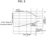
- Fig. 5 is a drawing that shows a relation between the flow rate change of pressure oil flowing through the main flow passage F1 and the circuit pressure during an arm raising motion in the first embodiment.
- the flow rate (supply flow rate) supplied to the arm cylinder 2 is maintained at Q2 until the hoist height becomes H1 from the initial height in the arm raising motion.
- the flow rate Q2 is the total flow rate of the pressure oil discharged from the main pump 1 and the pressure oil discharged from the sub-pump 5. Further, when the hoist height reaches H1, the circuit pressure P becomes the cracking pressure Pc, and the relief valve 7A starts to open.
- the relief valve 7A whose pressure override characteristic is inferior to normal, the change of the flow rate Q of the pressure oil supplied to the arm cylinder 2 moderately changes while the hoist height changes from H1 to H2, and therefore the impact on the operator operating the arm cylinder 2 with a lever is reduced.
- a relief valve having excellent pressure override characteristic is employed, since the flow rate sharply drops from Q2 to Q1 at once at the time point the hoist height is H1, the impact on the operator is larger compared to the relief valve 7A.
- the hoist height H1 and H2 is a height region corresponding to the height of finishing the arm raising motion after the dump truck loading work for example.
- Fig. 6 is a flowchart that shows a modification of the procedure of the control process of the directional solenoid valve 8A executed by the controller 30.
- this modification it is characterized in a point the directional solenoid valve 8A is turned to ON when a predetermined time elapses after the circuit pressure P becomes equal to or greater than the cracking pressure Pc.
- the circuit pressure determination section 31 determines whether or not the circuit pressure P is equal to or greater than the cracking pressure Pc (S11).
- the unload command output section 32 determines whether or not the elapsed time t is equal to or greater than a predetermined time t1 (S12). If “Yes” in S12, the unload command output section 32 outputs an operation command to the directional solenoid valve 8A, and turns the directional solenoid valve 8A to ON (S13). Also, merging of the main flow passage F1 and the sub-flow passage F2 is cancelled. Meanwhile, if "No" in S11 and S12, the process returns to S11.
- 1 second for example is set (stored) beforehand in the controller 30.
- This 1 second is the time when the pressure rises from the cracking pressure Pc to the set pressure Pr. That is to say, in this modification, it is controlled so that the directional solenoid valve 8A is turned to ON regarding that the circuit pressure P has reached the set pressure Pr when the circuit pressure P reaches the cracking pressure Pc and 1 second elapses instead that the circuit pressure P reaches the set pressure Pr and the directional solenoid valve 8A is turned to ON.
- the change of the flow rate can be made moderate similarly to Fig. 5 , the impact on the operator operating the arm cylinder 2 with a lever can be reduced.
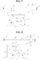
- Fig. 7 is a hydraulic circuit diagram that shows a hydraulic drive device for a work vehicle according to a second embodiment not covered by the claimed invention.
- a point configured to achieve an unload state using a vented relief valve 7B is different from the fist embodiment. Therefore, in the explanation below, explanation will be made focusing this different point, a configuration same to that of the first embodiment will be marked with a same reference sign, and explanation thereof will be omitted.
- the directional solenoid valve 6B is opened by the controller 30 (the unload function becomes ON), the vent circuit pressure of the vented relief valve 7B drops to the tank pressure, and thereby the set pressure drops. Therefore, pressure oil discharged from the sub-pump 5 passes through the branch pipe 14 and the vented relief valve 7B, and returns to the tank 13. Thereby, the sub-flow passage F2 is put into an unload state.
- the controller 30 controls the directional solenoid valve 6B so as to open, and the sub-flow passage F2 is forcibly put into an unload state.
- Fig. 8 is a hydraulic circuit diagram that shows a hydraulic drive device for a work vehicle according to a third embodiment of the present invention.
- a point configured to achieve an unload state using the vented relief valve 7B, the unload directional valve 6A, and the directional solenoid valve 6B is different from the first and second embodiments.
- a configuration same to that of the first and second embodiments will be marked with a same reference sign, and explanation thereof will be omitted.
- this third embodiment also, actions and effects similar to those of the first and second embodiment can be exhibited. Also, since the third embodiment is configured to return the pressure oil from the sub-pump 5 to the tank 13 through the unload directional valve 6A, the pressure loss can be reduced compared to a configuration of returning the pressure oil from the sub-pump 5 to the tank 13 through the vented relief valve 7B as the second embodiment. Therefore, the third embodiment has a higher energy saving effect compared to the second embodiment.
- Fig. 9 is a hydraulic circuit diagram that shows a hydraulic drive device for a work vehicle according to a fourth embodiment of the present invention.
- the fourth embodiment is different from the first embodiment in a point configured to operate the unload directional valve 6A using a proportional solenoid valve 8B instead of the directional solenoid valve 8A. Therefore, the procedure of the control process by the controller 30 is different.
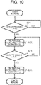
- Fig. 10 is a flowchart that shows a procedure of the control process of the proportional solenoid valve 8B executed by the controller 30.
- ⁇ /1 is an electric current increment per unit time of the proportional solenoid valve 8B.
- the circuit pressure determination section 31 determines whether or not the circuit pressure P has exceeded the set pressure Pr (S23). If “Yes” in S23, the unload command output section 32 applies the maximum value (Imax) of the control current I to the proportional solenoid valve 8B (S24). Also, merging of the main flow passage F1 and the sub-flow passage F2 is cancelled. Further, the process returns to S21 if "No” in S21, and the process returns to S22 if "No" in S23.
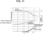
- Fig. 11 is a drawing that shows a relation between the flow rate change of pressure oil flowing through the main flow passage F1 and the circuit pressure during an arm raising motion in the fourth embodiment.
- the fourth embodiment is different from the first embodiment in that the electric current is applied gradually to the proportional solenoid valve 8B and the spool opening of the proportional solenoid valve 8B gradually opens while the hoist height changes from H1 to H2.
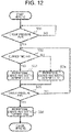
- Fig. 12 is a flowchart that shows a first modification of the procedure of the control process of the proportional solenoid valve 8B executed by the controller 30.
- the circuit pressure determination section 31 determines whether or not the circuit pressure P is equal to or greater than the cracking pressure Pc (S31). If "Yes" in S31, the timer not illustrated works, and the elapsed time t after the circuit pressure P reaches the cracking pressure Pc is measured.
- the unload command output section 32 determines whether or not the elapsed time t is less than the predetermined time t1 (S32). Also, similarly to Fig. 6 , the predetermined time t1 is set to 1 second.
- the circuit pressure determination section 31 determines whether or not the circuit pressure P has exceeded the set pressure Pr (S35). If "Yes” in S35, the unload command output section 32 applies the maximum value (Imax) of the control current I to the proportional solenoid valve 8B (S36).
- Fig. 13 is a flowchart that shows a second modification of the procedure of the control process of the proportional solenoid valve 8B executed by the controller 30.
- the circuit pressure determination section 31 determines whether or not the circuit pressure P is less than the cracking pressure Pc (S41). If “Yes” in S41, the circuit pressure determination section 31 determines whether or not the pressure change amount ⁇ P per unit time of the circuit pressure P is equal to or greater than a threshold value ⁇ P2 (S42). If "Yes" in S42, the unload command output section 32 applies the maximum value (Imax) of the control current I to the proportional solenoid valve 8B (S43).
- Fig. 14 is a hydraulic circuit diagram that shows a hydraulic drive device for a work vehicle according to a fifth embodiment not covered by the claimed invention.
- the fifth embodiment is obtained by arranging a proportional solenoid valve 6C instead of the directional solenoid valve 6B of the second embodiment shown in Fig. 7 . Even in this configuration, actions and effects similar to those of the second embodiment can be exhibited.
- Fig. 15 is a hydraulic circuit diagram that shows a hydraulic drive device for a work vehicle according to a sixth embodiment of the present invention.
- the sixth embodiment is obtained by arranging the proportional solenoid valve 6C instead of the directional solenoid valve 6B of the third embodiment shown in Fig. 8 . Even in this configuration, actions and effects similar to those of the third embodiment can be exhibited.
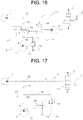
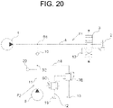
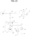
- Fig. 16 to Fig. 21 are hydraulic circuit diagrams that show a hydraulic drive device for a work vehicle according to seventh to twelfth embodiments, wherein the eighth and the eleventh embodiments are not part of the claimed invention.
- Fig. 16 to Fig. 21 have a configuration same to that of Fig. 1 , Fig. 7 ,
- Fig. 8 , Fig. 9 , Fig. 14 , and Fig. 15 respectively, they are different in whether or not being unloaded in a normal state. That is to say, between the first to sixth embodiments and the seventh to twelfth embodiments, setting of the initial position of the unload directional valve 6A, the initial position of the directional solenoid valve 6B, or the initial position of the proportional solenoid valve 6C becomes opposite. Even in these seventh to twelfth embodiments, such point remains unchanged that the impact of the time the operator executes a lever operation can be reduced.
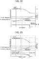
- Fig. 22 is a drawing that shows a relation between the flow rate change of pressure oil flowing through the main flow passage F1 and the circuit pressure during an arm raising motion in the seventh to ninth embodiments shown in Fig. 16 to Fig. 18 .
- Fig. 23 is a drawing that shows a relation between the flow rate change of pressure oil flowing through the main flow passage F1 and the circuit pressure during an arm raising motion in the tenth to twelfth embodiments shown in Fig. 19 to Fig. 21 .
- Fig. 22 is opposite in terms of the behavior of the directional solenoid valve, but is same in that the flow rate Q moderately reduces in the range of the hoist height H1 to H2.
- Fig. 23 is opposite in terms of the behavior of the proportional valve electric current and the spool opening, but is same in that the flow rate Q moderately reduces in the range of the hoist height H1 to H2. Therefore, even in the configuration of the seventh to twelfth embodiments, the impact on the operator at the time of operating the arm cylinder 2 is reduced.
- the flow rate Q of the main flow passage F1 can be reduced gradually taking an advantage of the characteristic of the relief valve, and therefore the impact on the operator at the time of operation of the arm cylinder 2 with a lever can be suppressed. That is to say, since the impact on the operator is reduced by moderating the change of the flow rate at the time of switching merging of the main flow passage F1 and the sub-flow passage F2, operability of the arm cylinder improves.
- the arm cylinder can be operated by an intention of an operator, and usability is excellent. Further, by returning the pressure oil to the tank 13 at the time of unloading, energy loss can be suppressed. Furthermore, by employing a gear pump as the sub-pump 5, the hydraulic drive device can be produced at a low cost.
- the work vehicle to which the hydraulic drive device according to the present invention is applied is not limited to a wheel loader, and may be a fork lift, bulldozer, hydraulic excavator, and so on.
- the hydraulic drive device according to the present invention can be applied to various kinds of hydraulic actuators such as a bucket cylinder and a steering cylinder in addition to the arm cylinder.
Landscapes
- Engineering & Computer Science (AREA)
- General Engineering & Computer Science (AREA)
- Mining & Mineral Resources (AREA)
- Civil Engineering (AREA)
- Structural Engineering (AREA)
- Physics & Mathematics (AREA)
- Fluid Mechanics (AREA)
- Mechanical Engineering (AREA)
- Fluid-Pressure Circuits (AREA)
- Operation Control Of Excavators (AREA)
Applications Claiming Priority (2)
| Application Number | Priority Date | Filing Date | Title |
|---|---|---|---|
| JP2017068952A JP6901892B2 (ja) | 2017-03-30 | 2017-03-30 | 作業車両の油圧駆動装置 |
| PCT/JP2018/008864 WO2018180323A1 (ja) | 2017-03-30 | 2018-03-07 | 作業車両の油圧駆動装置 |
Publications (3)
| Publication Number | Publication Date |
|---|---|
| EP3492753A1 EP3492753A1 (en) | 2019-06-05 |
| EP3492753A4 EP3492753A4 (en) | 2020-02-26 |
| EP3492753B1 true EP3492753B1 (en) | 2022-07-20 |
Family
ID=63675268
Family Applications (1)
| Application Number | Title | Priority Date | Filing Date |
|---|---|---|---|
| EP18775063.3A Active EP3492753B1 (en) | 2017-03-30 | 2018-03-07 | Hydraulic drive device for working vehicle |
Country Status (5)
| Country | Link |
|---|---|
| US (1) | US10900200B2 (enExample) |
| EP (1) | EP3492753B1 (enExample) |
| JP (1) | JP6901892B2 (enExample) |
| CN (1) | CN109563852B (enExample) |
| WO (1) | WO2018180323A1 (enExample) |
Families Citing this family (2)
| Publication number | Priority date | Publication date | Assignee | Title |
|---|---|---|---|---|
| JP7492815B2 (ja) * | 2019-09-03 | 2024-05-30 | ナブテスコ株式会社 | 流体制御弁、流体システム、建設機械および制御方法 |
| CN118686817B (zh) * | 2024-07-04 | 2025-12-26 | 潍柴动力股份有限公司 | 一种液压控制阀系统及装载机 |
Family Cites Families (9)
| Publication number | Priority date | Publication date | Assignee | Title |
|---|---|---|---|---|
| JPH0640238Y2 (ja) | 1989-09-06 | 1994-10-19 | 東洋運搬機株式会社 | 荷役車両の上昇速度制御装置 |
| JPH0914215A (ja) * | 1995-06-27 | 1997-01-14 | Shin Caterpillar Mitsubishi Ltd | 冷却器を備えた油圧回路装置 |
| JPH10266274A (ja) * | 1997-03-27 | 1998-10-06 | Hitachi Constr Mach Co Ltd | 建設機械の油圧回路装置 |
| JPH11166248A (ja) * | 1997-12-05 | 1999-06-22 | Komatsu Ltd | 油圧駆動式作業車両 |
| US6112848A (en) * | 1998-09-23 | 2000-09-05 | Chrysler Corporation | Sound-dampened automobile interior components and methods for making same |
| JP4272207B2 (ja) | 2003-11-14 | 2009-06-03 | 株式会社小松製作所 | 建設機械の油圧制御装置 |
| JP2006083990A (ja) * | 2004-09-17 | 2006-03-30 | Hitachi Constr Mach Co Ltd | 油圧駆動装置 |
| CN102229328B (zh) * | 2011-05-05 | 2013-05-08 | 四川大学 | 一种多泵合流的车辆机械节能液压系统 |
| CN203926175U (zh) | 2014-05-30 | 2014-11-05 | 贝特(杭州)工业机械有限公司 | 一种压力继电器可控双速液压装置 |
-
2017
- 2017-03-30 JP JP2017068952A patent/JP6901892B2/ja active Active
-
2018
- 2018-03-07 EP EP18775063.3A patent/EP3492753B1/en active Active
- 2018-03-07 US US16/328,840 patent/US10900200B2/en active Active
- 2018-03-07 WO PCT/JP2018/008864 patent/WO2018180323A1/ja not_active Ceased
- 2018-03-07 CN CN201880003135.XA patent/CN109563852B/zh active Active
Also Published As
| Publication number | Publication date |
|---|---|
| US20190249396A1 (en) | 2019-08-15 |
| WO2018180323A1 (ja) | 2018-10-04 |
| EP3492753A4 (en) | 2020-02-26 |
| CN109563852B (zh) | 2020-11-06 |
| JP6901892B2 (ja) | 2021-07-14 |
| EP3492753A1 (en) | 2019-06-05 |
| CN109563852A (zh) | 2019-04-02 |
| US10900200B2 (en) | 2021-01-26 |
| JP2018168657A (ja) | 2018-11-01 |
Similar Documents
| Publication | Publication Date | Title |
|---|---|---|
| CN101107400B (zh) | 建筑机械的控制模式切换装置以及建筑机械 | |
| US10408238B2 (en) | Control strategy for hydraulic actuator with a pair of independent metering valves | |
| EP3305994B1 (en) | Control system for construction machinery and control method for construction machinery | |
| US10041224B2 (en) | Liquid-pressure driving system | |
| EP3795843B1 (en) | Construction machine | |
| CN111094111B (zh) | 轮式装载机 | |
| JP7071339B2 (ja) | 建設機械の制御システム及び建設機械の制御方法 | |
| KR102246421B1 (ko) | 건설기계의 제어 시스템 및 건설기계의 제어 방법 | |
| EP3505688A1 (en) | System for controlling construction machinery and method for controlling construction machinery | |
| EP3280847B1 (en) | A load sensing hydraulic system for a working machine, and a method for controlling a load sensing hydraulic system | |
| US10900200B2 (en) | Hydraulic drive device for work vehicle | |
| JP2014506662A (ja) | 過負荷時に待機モードとなる負荷検知制御 | |
| AU2019280021B2 (en) | Hydraulic drive device for industrial vehicle | |
| US11408145B2 (en) | Work vehicle and hydraulic control method | |
| KR102141511B1 (ko) | 건설장비에서의 유압펌프 유량 제어 시스템 | |
| KR102849222B1 (ko) | 구동 장치 및 건설 기계 | |
| KR101343831B1 (ko) | 지게차의 유압시스템 | |
| KR100884870B1 (ko) | 굴삭기용 콘트롤 밸브의 가변우선 시스템 | |
| KR20050083302A (ko) | 굴삭기 작업장치의 가변우선 시스템 | |
| US20250376993A1 (en) | Hydraulic drive device | |
| EP4717927A1 (en) | Hydraulic drive device | |
| JP6135398B2 (ja) | バルブ装置 |
Legal Events
| Date | Code | Title | Description |
|---|---|---|---|
| STAA | Information on the status of an ep patent application or granted ep patent |
Free format text: STATUS: THE INTERNATIONAL PUBLICATION HAS BEEN MADE |
|
| PUAI | Public reference made under article 153(3) epc to a published international application that has entered the european phase |
Free format text: ORIGINAL CODE: 0009012 |
|
| STAA | Information on the status of an ep patent application or granted ep patent |
Free format text: STATUS: REQUEST FOR EXAMINATION WAS MADE |
|
| 17P | Request for examination filed |
Effective date: 20190227 |
|
| AK | Designated contracting states |
Kind code of ref document: A1 Designated state(s): AL AT BE BG CH CY CZ DE DK EE ES FI FR GB GR HR HU IE IS IT LI LT LU LV MC MK MT NL NO PL PT RO RS SE SI SK SM TR |
|
| AX | Request for extension of the european patent |
Extension state: BA ME |
|
| RAP1 | Party data changed (applicant data changed or rights of an application transferred) |
Owner name: HITACHI CONSTRUCTION MACHINERY CO., LTD. |
|
| A4 | Supplementary search report drawn up and despatched |
Effective date: 20200129 |
|
| RIC1 | Information provided on ipc code assigned before grant |
Ipc: F15B 11/048 20060101ALN20200123BHEP Ipc: F15B 11/17 20060101ALN20200123BHEP Ipc: F15B 11/02 20060101AFI20200123BHEP Ipc: E02F 9/22 20060101ALI20200123BHEP Ipc: F15B 11/042 20060101ALI20200123BHEP Ipc: F15B 11/028 20060101ALI20200123BHEP |
|
| DAV | Request for validation of the european patent (deleted) | ||
| DAX | Request for extension of the european patent (deleted) | ||
| STAA | Information on the status of an ep patent application or granted ep patent |
Free format text: STATUS: EXAMINATION IS IN PROGRESS |
|
| 17Q | First examination report despatched |
Effective date: 20210301 |
|
| GRAP | Despatch of communication of intention to grant a patent |
Free format text: ORIGINAL CODE: EPIDOSNIGR1 |
|
| STAA | Information on the status of an ep patent application or granted ep patent |
Free format text: STATUS: GRANT OF PATENT IS INTENDED |
|
| RIC1 | Information provided on ipc code assigned before grant |
Ipc: F15B 11/048 20060101ALN20220105BHEP Ipc: F15B 11/17 20060101ALN20220105BHEP Ipc: F15B 11/042 20060101ALI20220105BHEP Ipc: F15B 11/028 20060101ALI20220105BHEP Ipc: E02F 9/22 20060101ALI20220105BHEP Ipc: F15B 11/02 20060101AFI20220105BHEP |
|
| INTG | Intention to grant announced |
Effective date: 20220202 |
|
| GRAS | Grant fee paid |
Free format text: ORIGINAL CODE: EPIDOSNIGR3 |
|
| GRAA | (expected) grant |
Free format text: ORIGINAL CODE: 0009210 |
|
| STAA | Information on the status of an ep patent application or granted ep patent |
Free format text: STATUS: THE PATENT HAS BEEN GRANTED |
|
| AK | Designated contracting states |
Kind code of ref document: B1 Designated state(s): AL AT BE BG CH CY CZ DE DK EE ES FI FR GB GR HR HU IE IS IT LI LT LU LV MC MK MT NL NO PL PT RO RS SE SI SK SM TR |
|
| RIN1 | Information on inventor provided before grant (corrected) |
Inventor name: TANAKA, SHINICHIRO |
|
| REG | Reference to a national code |
Ref country code: CH Ref legal event code: EP |
|
| REG | Reference to a national code |
Ref country code: DE Ref legal event code: R096 Ref document number: 602018038184 Country of ref document: DE |
|
| REG | Reference to a national code |
Ref country code: AT Ref legal event code: REF Ref document number: 1505681 Country of ref document: AT Kind code of ref document: T Effective date: 20220815 |
|
| REG | Reference to a national code |
Ref country code: IE Ref legal event code: FG4D |
|
| REG | Reference to a national code |
Ref country code: LT Ref legal event code: MG9D |
|
| REG | Reference to a national code |
Ref country code: NL Ref legal event code: MP Effective date: 20220720 |
|
| PG25 | Lapsed in a contracting state [announced via postgrant information from national office to epo] |
Ref country code: SE Free format text: LAPSE BECAUSE OF FAILURE TO SUBMIT A TRANSLATION OF THE DESCRIPTION OR TO PAY THE FEE WITHIN THE PRESCRIBED TIME-LIMIT Effective date: 20220720 Ref country code: RS Free format text: LAPSE BECAUSE OF FAILURE TO SUBMIT A TRANSLATION OF THE DESCRIPTION OR TO PAY THE FEE WITHIN THE PRESCRIBED TIME-LIMIT Effective date: 20220720 Ref country code: PT Free format text: LAPSE BECAUSE OF FAILURE TO SUBMIT A TRANSLATION OF THE DESCRIPTION OR TO PAY THE FEE WITHIN THE PRESCRIBED TIME-LIMIT Effective date: 20221121 Ref country code: NO Free format text: LAPSE BECAUSE OF FAILURE TO SUBMIT A TRANSLATION OF THE DESCRIPTION OR TO PAY THE FEE WITHIN THE PRESCRIBED TIME-LIMIT Effective date: 20221020 Ref country code: NL Free format text: LAPSE BECAUSE OF FAILURE TO SUBMIT A TRANSLATION OF THE DESCRIPTION OR TO PAY THE FEE WITHIN THE PRESCRIBED TIME-LIMIT Effective date: 20220720 Ref country code: LV Free format text: LAPSE BECAUSE OF FAILURE TO SUBMIT A TRANSLATION OF THE DESCRIPTION OR TO PAY THE FEE WITHIN THE PRESCRIBED TIME-LIMIT Effective date: 20220720 Ref country code: LT Free format text: LAPSE BECAUSE OF FAILURE TO SUBMIT A TRANSLATION OF THE DESCRIPTION OR TO PAY THE FEE WITHIN THE PRESCRIBED TIME-LIMIT Effective date: 20220720 Ref country code: FI Free format text: LAPSE BECAUSE OF FAILURE TO SUBMIT A TRANSLATION OF THE DESCRIPTION OR TO PAY THE FEE WITHIN THE PRESCRIBED TIME-LIMIT Effective date: 20220720 Ref country code: ES Free format text: LAPSE BECAUSE OF FAILURE TO SUBMIT A TRANSLATION OF THE DESCRIPTION OR TO PAY THE FEE WITHIN THE PRESCRIBED TIME-LIMIT Effective date: 20220720 |
|
| REG | Reference to a national code |
Ref country code: AT Ref legal event code: MK05 Ref document number: 1505681 Country of ref document: AT Kind code of ref document: T Effective date: 20220720 |
|
| PG25 | Lapsed in a contracting state [announced via postgrant information from national office to epo] |
Ref country code: PL Free format text: LAPSE BECAUSE OF FAILURE TO SUBMIT A TRANSLATION OF THE DESCRIPTION OR TO PAY THE FEE WITHIN THE PRESCRIBED TIME-LIMIT Effective date: 20220720 Ref country code: IS Free format text: LAPSE BECAUSE OF FAILURE TO SUBMIT A TRANSLATION OF THE DESCRIPTION OR TO PAY THE FEE WITHIN THE PRESCRIBED TIME-LIMIT Effective date: 20221120 Ref country code: HR Free format text: LAPSE BECAUSE OF FAILURE TO SUBMIT A TRANSLATION OF THE DESCRIPTION OR TO PAY THE FEE WITHIN THE PRESCRIBED TIME-LIMIT Effective date: 20220720 Ref country code: GR Free format text: LAPSE BECAUSE OF FAILURE TO SUBMIT A TRANSLATION OF THE DESCRIPTION OR TO PAY THE FEE WITHIN THE PRESCRIBED TIME-LIMIT Effective date: 20221021 |
|
| REG | Reference to a national code |
Ref country code: DE Ref legal event code: R097 Ref document number: 602018038184 Country of ref document: DE |
|
| PG25 | Lapsed in a contracting state [announced via postgrant information from national office to epo] |
Ref country code: SM Free format text: LAPSE BECAUSE OF FAILURE TO SUBMIT A TRANSLATION OF THE DESCRIPTION OR TO PAY THE FEE WITHIN THE PRESCRIBED TIME-LIMIT Effective date: 20220720 Ref country code: RO Free format text: LAPSE BECAUSE OF FAILURE TO SUBMIT A TRANSLATION OF THE DESCRIPTION OR TO PAY THE FEE WITHIN THE PRESCRIBED TIME-LIMIT Effective date: 20220720 Ref country code: DK Free format text: LAPSE BECAUSE OF FAILURE TO SUBMIT A TRANSLATION OF THE DESCRIPTION OR TO PAY THE FEE WITHIN THE PRESCRIBED TIME-LIMIT Effective date: 20220720 Ref country code: CZ Free format text: LAPSE BECAUSE OF FAILURE TO SUBMIT A TRANSLATION OF THE DESCRIPTION OR TO PAY THE FEE WITHIN THE PRESCRIBED TIME-LIMIT Effective date: 20220720 Ref country code: AT Free format text: LAPSE BECAUSE OF FAILURE TO SUBMIT A TRANSLATION OF THE DESCRIPTION OR TO PAY THE FEE WITHIN THE PRESCRIBED TIME-LIMIT Effective date: 20220720 |
|
| PLBE | No opposition filed within time limit |
Free format text: ORIGINAL CODE: 0009261 |
|
| STAA | Information on the status of an ep patent application or granted ep patent |
Free format text: STATUS: NO OPPOSITION FILED WITHIN TIME LIMIT |
|
| PG25 | Lapsed in a contracting state [announced via postgrant information from national office to epo] |
Ref country code: SK Free format text: LAPSE BECAUSE OF FAILURE TO SUBMIT A TRANSLATION OF THE DESCRIPTION OR TO PAY THE FEE WITHIN THE PRESCRIBED TIME-LIMIT Effective date: 20220720 Ref country code: EE Free format text: LAPSE BECAUSE OF FAILURE TO SUBMIT A TRANSLATION OF THE DESCRIPTION OR TO PAY THE FEE WITHIN THE PRESCRIBED TIME-LIMIT Effective date: 20220720 |
|
| 26N | No opposition filed |
Effective date: 20230421 |
|
| PG25 | Lapsed in a contracting state [announced via postgrant information from national office to epo] |
Ref country code: AL Free format text: LAPSE BECAUSE OF FAILURE TO SUBMIT A TRANSLATION OF THE DESCRIPTION OR TO PAY THE FEE WITHIN THE PRESCRIBED TIME-LIMIT Effective date: 20220720 |
|
| PG25 | Lapsed in a contracting state [announced via postgrant information from national office to epo] |
Ref country code: SI Free format text: LAPSE BECAUSE OF FAILURE TO SUBMIT A TRANSLATION OF THE DESCRIPTION OR TO PAY THE FEE WITHIN THE PRESCRIBED TIME-LIMIT Effective date: 20220720 |
|
| PG25 | Lapsed in a contracting state [announced via postgrant information from national office to epo] |
Ref country code: MC Free format text: LAPSE BECAUSE OF FAILURE TO SUBMIT A TRANSLATION OF THE DESCRIPTION OR TO PAY THE FEE WITHIN THE PRESCRIBED TIME-LIMIT Effective date: 20220720 |
|
| REG | Reference to a national code |
Ref country code: CH Ref legal event code: PL |
|
| GBPC | Gb: european patent ceased through non-payment of renewal fee |
Effective date: 20230307 |
|
| REG | Reference to a national code |
Ref country code: BE Ref legal event code: MM Effective date: 20230331 |
|
| PG25 | Lapsed in a contracting state [announced via postgrant information from national office to epo] |
Ref country code: LU Free format text: LAPSE BECAUSE OF NON-PAYMENT OF DUE FEES Effective date: 20230307 |
|
| REG | Reference to a national code |
Ref country code: IE Ref legal event code: MM4A |
|
| PG25 | Lapsed in a contracting state [announced via postgrant information from national office to epo] |
Ref country code: GB Free format text: LAPSE BECAUSE OF NON-PAYMENT OF DUE FEES Effective date: 20230307 |
|
| PG25 | Lapsed in a contracting state [announced via postgrant information from national office to epo] |
Ref country code: LI Free format text: LAPSE BECAUSE OF NON-PAYMENT OF DUE FEES Effective date: 20230331 Ref country code: IE Free format text: LAPSE BECAUSE OF NON-PAYMENT OF DUE FEES Effective date: 20230307 Ref country code: GB Free format text: LAPSE BECAUSE OF NON-PAYMENT OF DUE FEES Effective date: 20230307 Ref country code: FR Free format text: LAPSE BECAUSE OF NON-PAYMENT OF DUE FEES Effective date: 20230331 Ref country code: CH Free format text: LAPSE BECAUSE OF NON-PAYMENT OF DUE FEES Effective date: 20230331 |
|
| PG25 | Lapsed in a contracting state [announced via postgrant information from national office to epo] |
Ref country code: BE Free format text: LAPSE BECAUSE OF NON-PAYMENT OF DUE FEES Effective date: 20230331 |
|
| PG25 | Lapsed in a contracting state [announced via postgrant information from national office to epo] |
Ref country code: IT Free format text: LAPSE BECAUSE OF FAILURE TO SUBMIT A TRANSLATION OF THE DESCRIPTION OR TO PAY THE FEE WITHIN THE PRESCRIBED TIME-LIMIT Effective date: 20220720 |
|
| PG25 | Lapsed in a contracting state [announced via postgrant information from national office to epo] |
Ref country code: BG Free format text: LAPSE BECAUSE OF FAILURE TO SUBMIT A TRANSLATION OF THE DESCRIPTION OR TO PAY THE FEE WITHIN THE PRESCRIBED TIME-LIMIT Effective date: 20220720 |
|
| PG25 | Lapsed in a contracting state [announced via postgrant information from national office to epo] |
Ref country code: BG Free format text: LAPSE BECAUSE OF FAILURE TO SUBMIT A TRANSLATION OF THE DESCRIPTION OR TO PAY THE FEE WITHIN THE PRESCRIBED TIME-LIMIT Effective date: 20220720 |
|
| PG25 | Lapsed in a contracting state [announced via postgrant information from national office to epo] |
Ref country code: CY Free format text: LAPSE BECAUSE OF FAILURE TO SUBMIT A TRANSLATION OF THE DESCRIPTION OR TO PAY THE FEE WITHIN THE PRESCRIBED TIME-LIMIT; INVALID AB INITIO Effective date: 20180307 |
|
| PG25 | Lapsed in a contracting state [announced via postgrant information from national office to epo] |
Ref country code: HU Free format text: LAPSE BECAUSE OF FAILURE TO SUBMIT A TRANSLATION OF THE DESCRIPTION OR TO PAY THE FEE WITHIN THE PRESCRIBED TIME-LIMIT; INVALID AB INITIO Effective date: 20180307 |
|
| PG25 | Lapsed in a contracting state [announced via postgrant information from national office to epo] |
Ref country code: TR Free format text: LAPSE BECAUSE OF FAILURE TO SUBMIT A TRANSLATION OF THE DESCRIPTION OR TO PAY THE FEE WITHIN THE PRESCRIBED TIME-LIMIT Effective date: 20220720 |
|
| PGFP | Annual fee paid to national office [announced via postgrant information from national office to epo] |
Ref country code: DE Payment date: 20260128 Year of fee payment: 9 |