EP3489518A1 - Vacuum pump and assembly and method for handling and/or assembly of a vacuum pump - Google Patents
Vacuum pump and assembly and method for handling and/or assembly of a vacuum pump Download PDFInfo
- Publication number
- EP3489518A1 EP3489518A1 EP17203998.4A EP17203998A EP3489518A1 EP 3489518 A1 EP3489518 A1 EP 3489518A1 EP 17203998 A EP17203998 A EP 17203998A EP 3489518 A1 EP3489518 A1 EP 3489518A1
- Authority
- EP
- European Patent Office
- Prior art keywords
- pump
- engagement structure
- vacuum pump
- pump body
- housing
- Prior art date
- Legal status (The legal status is an assumption and is not a legal conclusion. Google has not performed a legal analysis and makes no representation as to the accuracy of the status listed.)
- Granted
Links
- 238000000034 method Methods 0.000 title claims description 15
- 230000005484 gravity Effects 0.000 claims abstract description 34
- 238000003780 insertion Methods 0.000 claims description 36
- 230000037431 insertion Effects 0.000 claims description 36
- 238000003754 machining Methods 0.000 claims description 4
- 238000003801 milling Methods 0.000 claims description 4
- 230000002787 reinforcement Effects 0.000 claims description 3
- 239000007789 gas Substances 0.000 description 15
- 238000005086 pumping Methods 0.000 description 10
- 239000002826 coolant Substances 0.000 description 9
- 238000013461 design Methods 0.000 description 5
- 238000005096 rolling process Methods 0.000 description 5
- 238000004519 manufacturing process Methods 0.000 description 4
- 238000007789 sealing Methods 0.000 description 4
- 239000007921 spray Substances 0.000 description 4
- 238000003860 storage Methods 0.000 description 4
- 230000006378 damage Effects 0.000 description 3
- 238000010926 purge Methods 0.000 description 3
- 239000000725 suspension Substances 0.000 description 3
- IJGRMHOSHXDMSA-UHFFFAOYSA-N Atomic nitrogen Chemical compound N#N IJGRMHOSHXDMSA-UHFFFAOYSA-N 0.000 description 2
- 208000027418 Wounds and injury Diseases 0.000 description 2
- 230000015572 biosynthetic process Effects 0.000 description 2
- 230000000295 complement effect Effects 0.000 description 2
- 238000010276 construction Methods 0.000 description 2
- 238000006073 displacement reaction Methods 0.000 description 2
- 208000014674 injury Diseases 0.000 description 2
- 238000009434 installation Methods 0.000 description 2
- 125000006850 spacer group Chemical group 0.000 description 2
- 230000002745 absorbent Effects 0.000 description 1
- 239000002250 absorbent Substances 0.000 description 1
- 238000004026 adhesive bonding Methods 0.000 description 1
- 230000005540 biological transmission Effects 0.000 description 1
- 239000002981 blocking agent Substances 0.000 description 1
- 230000000903 blocking effect Effects 0.000 description 1
- 238000001816 cooling Methods 0.000 description 1
- 230000008878 coupling Effects 0.000 description 1
- 238000010168 coupling process Methods 0.000 description 1
- 238000005859 coupling reaction Methods 0.000 description 1
- 230000001419 dependent effect Effects 0.000 description 1
- 238000007598 dipping method Methods 0.000 description 1
- 238000007654 immersion Methods 0.000 description 1
- 238000002347 injection Methods 0.000 description 1
- 239000007924 injection Substances 0.000 description 1
- 238000005304 joining Methods 0.000 description 1
- 239000000314 lubricant Substances 0.000 description 1
- 230000001050 lubricating effect Effects 0.000 description 1
- 238000012423 maintenance Methods 0.000 description 1
- 238000013508 migration Methods 0.000 description 1
- 230000005012 migration Effects 0.000 description 1
- 229910052757 nitrogen Inorganic materials 0.000 description 1
- 238000003825 pressing Methods 0.000 description 1
- 238000007493 shaping process Methods 0.000 description 1
Images


Classifications
-
- F—MECHANICAL ENGINEERING; LIGHTING; HEATING; WEAPONS; BLASTING
- F04—POSITIVE - DISPLACEMENT MACHINES FOR LIQUIDS; PUMPS FOR LIQUIDS OR ELASTIC FLUIDS
- F04D—NON-POSITIVE-DISPLACEMENT PUMPS
- F04D29/00—Details, component parts, or accessories
- F04D29/60—Mounting; Assembling; Disassembling
- F04D29/601—Mounting; Assembling; Disassembling specially adapted for elastic fluid pumps
-
- F—MECHANICAL ENGINEERING; LIGHTING; HEATING; WEAPONS; BLASTING
- F04—POSITIVE - DISPLACEMENT MACHINES FOR LIQUIDS; PUMPS FOR LIQUIDS OR ELASTIC FLUIDS
- F04D—NON-POSITIVE-DISPLACEMENT PUMPS
- F04D19/00—Axial-flow pumps
- F04D19/02—Multi-stage pumps
- F04D19/04—Multi-stage pumps specially adapted to the production of a high vacuum, e.g. molecular pumps
- F04D19/042—Turbomolecular vacuum pumps
-
- F—MECHANICAL ENGINEERING; LIGHTING; HEATING; WEAPONS; BLASTING
- F04—POSITIVE - DISPLACEMENT MACHINES FOR LIQUIDS; PUMPS FOR LIQUIDS OR ELASTIC FLUIDS
- F04D—NON-POSITIVE-DISPLACEMENT PUMPS
- F04D29/00—Details, component parts, or accessories
- F04D29/40—Casings; Connections of working fluid
- F04D29/52—Casings; Connections of working fluid for axial pumps
- F04D29/522—Casings; Connections of working fluid for axial pumps especially adapted for elastic fluid pumps
-
- F—MECHANICAL ENGINEERING; LIGHTING; HEATING; WEAPONS; BLASTING
- F05—INDEXING SCHEMES RELATING TO ENGINES OR PUMPS IN VARIOUS SUBCLASSES OF CLASSES F01-F04
- F05D—INDEXING SCHEME FOR ASPECTS RELATING TO NON-POSITIVE-DISPLACEMENT MACHINES OR ENGINES, GAS-TURBINES OR JET-PROPULSION PLANTS
- F05D2230/00—Manufacture
- F05D2230/60—Assembly methods
- F05D2230/64—Assembly methods using positioning or alignment devices for aligning or centring, e.g. pins
-
- F—MECHANICAL ENGINEERING; LIGHTING; HEATING; WEAPONS; BLASTING
- F05—INDEXING SCHEMES RELATING TO ENGINES OR PUMPS IN VARIOUS SUBCLASSES OF CLASSES F01-F04
- F05D—INDEXING SCHEME FOR ASPECTS RELATING TO NON-POSITIVE-DISPLACEMENT MACHINES OR ENGINES, GAS-TURBINES OR JET-PROPULSION PLANTS
- F05D2230/00—Manufacture
- F05D2230/60—Assembly methods
- F05D2230/68—Assembly methods using auxiliary equipment for lifting or holding
Definitions
- the present invention relates to a vacuum pump, in particular a turbomolecular pump, and to an arrangement and a method for handling and / or mounting a vacuum pump.
- Vacuum pumps are often used in systems that require a horizontal mounting of the respective vacuum pump. This applies in particular to turbomolecular pumps in pumping capacity classes greater than 1000 l / s. In the present case, the volume flow which can be conveyed per unit time through a cross-sectional area or a pump-effective section is regarded as the pumping speed. Such pumps may have a high weight due to the size of the construction. Therefore, such pumps are usually raised only with a lifting aid. Similarly, the orientation of the pump and its attachment to a respective system requires a suitable lifting aid.
- an object of the present invention is to provide a vacuum pump, which can be raised, aligned and / or mounted with reduced handling costs. Likewise, the object is to provide an arrangement and a method for handling and / or mounting a vacuum pump.
- a vacuum pump according to the invention which may be in particular a turbomolecular pump, has a pump body and a fastening device formed thereon, which has at least one engagement structure for connecting a fastening element to the pump body.
- the fastening element can be, for example, a sliding block (see, for example, DIN 508), which is introduced into the engagement structure and allows the screwing in of a so-called eye bolt or eyebolt (see, for example, DIN 580).
- the engagement structure on the outer circumference of the pump body extends at least in sections at an angle to its longitudinal extent. The engagement structure thus runs not or at least not exactly along the longitudinal extent of the pump body but at an angle to this. This allows the pump body to be oriented in the raised state about the longitudinal extent when a fastener is displaced within the engagement structure.
- a position and / or arrangement of the fastening device along the longitudinal extent, ie in the axial direction, of the pump body is selected as a function of the center of gravity of the pump body.
- a fastening element in or on the engagement structure, in particular in a positive connection, in order, for example, to establish a connection to a hoist via an eye bolt.
- a rotation of the pump body about the longitudinal axis can then be accomplished without the maintenance of the position of the longitudinal axis of the pump body in the room requires a lot of effort. Accordingly, easily and without the risk of tilting of the respectively used fastener in or on the engagement structure, the rotational position of the pump body about the longitudinal axis or longitudinal extent can be precisely adjusted. The entire handling and assembly effort can therefore be done with little manual effort.
- the engagement structure is designed for the displaceable guidance of a fastening element, in particular for a displaceable guide along a circumferential orientation of the pump body. Due to the sliding guide, the orientation of the rotational position of the pump body in the raised state can be done easily and without the risk of incorrect operation or injury. In particular, it is ensured by the displaceable guide that during a rotation of the pump body about the longitudinal axis and the associated displacement of a fastening means in or on the engagement structure, the fastening means does not tilt.
- the at least one engagement structure extends along a circumferential orientation of the pump body, in particular orthogonal or substantially orthogonal to the longitudinal extension of the pump body. In this way, an alignment of the pump body about the longitudinal axis or about the longitudinal extent can be made particularly easy to handle.
- the engagement structure may partially or completely circumscribe the outer circumference of the pump body.
- An engagement structure provided in sections permits alignment between two critical angle positions, so that an orientation specification for the final assembly position can be created by the position of the engagement structure formed in sections.
- the pump body in the raised state can be completely rotated about its own longitudinal axis, so that all rotational positions can be adjusted for the final assembly position.
- the engagement structure runs around the outer circumference. Accordingly, the engagement structure is annularly introduced into the outer periphery of the pump body or provided on this and thus endless educated. The beginning and end of the intervention structure are thus seamlessly merged in the latter embodiment.
- the at least one engagement structure is positioned axially at the height of the center of gravity of the pump body. Accordingly, the at least one engagement structure with respect to the longitudinal extent or longitudinal axis of the pump body is arranged in a position which coincides with the position of the center of gravity of the pump body along the longitudinal extent or longitudinal axis. In this way, a handling-friendly installation can be ensured with only one engagement structure. Thus, this arrangement of the engagement structure ensures that a substantially horizontal alignment of the pump body in the raised state of the vacuum pump can be maintained without additional support effort by the operator.
- the fastening device has a plurality of engagement structures.
- the fastening security for the respective lifting means and also the positional stability can be increased in the raised state of the pump.
- At least two engagement structures are positioned axially on both sides of the center of gravity of the pump body in an advantageous manner.
- the two engagement structures axially grasp the center of gravity. Seen along the longitudinal axis of the pump body is thus arranged an engagement structure in front of the center of gravity and another engagement structure behind the center of gravity. An undesirable inclination of the longitudinal axis in space during lifting and / or mounting of the vacuum pump can be safely avoided in this way.
- the axial distance of an engagement structure to the center of gravity is selected to coincide with the axial distance of a further engagement structure to the center of gravity. This ensures a uniform load on the respectively used load-receiving or lifting means and / or the respective suspension means of the hoist. It is also possible that the engagement structure have different axial distances to the center of gravity, whereby a greater freedom of design in the choice of the position of the individual engagement structures.
- the engagement structure is designed as a groove-like depression and / or for receiving at least one sliding block.
- a sliding block may preferably be displaceable within the groove-like depression.
- the groove-like depression is preferably a T-slot. Accordingly, the groove has a T-shape in cross-section, whereby in a particularly simple manner a positive coupling with a fastening element, which is designed in particular as a sliding block, can be generated.
- the at least one engagement structure is designed as a web-like projection and / or for guiding a complementary shaped fastener, in particular a sliding block with formed therein groove-like depression which engages around an example T-shaped web.
- Such web-like projections can be easily manufactured and also allow a secure attachment and appropriate guidance for complementary shaped fasteners.
- the engagement structure has an insertion section for a fastening element and / or wherein the insertion section for insertion of a fastening element is formed transversely to the longitudinal course of the engagement structure.
- the respective fastening element can only be introduced into the engagement structure for the implementation of the respective handling and assembly task or can be arranged to connect to it. After the handling and assembly task, the fastener can be removed again from the engagement structure and optionally reused.
- the insertion section may be formed by an interruption of the cross-sectional shape, in particular by an interruption of a T-shaped cross section and / or by omitting projections for the form-fitting engagement of a fastening element.
- the insertion section may be formed by a groove section which has a merely rectangular cross-section without projections or without a T-shape.
- the engagement structure may advantageously have a projection and / or a step for narrowing and / or reducing the cross-sectional area of the engagement structure.
- a projection and / or shoulder may preferably be provided in front of or behind the insertion section, for example by a shoulder in the surface of the circumferential engagement structure.
- this can be produced by machining, preferably by turning and / or milling.
- machining preferably by turning and / or milling.
- T-slot milling cutter for production, which is inexpensive to accomplish.
- the engagement structure can be introduced in particular by machining the pump body in this. Accordingly, for example, a part of the pump body can be produced by primary shaping and / or forming processes in its basic form and then introduce the engagement structure into the outer circumference of the pump body by means of a machining process or generate it. This can be realized with little manufacturing effort.
- the pump body is formed by a housing and at least one pump component arranged in and / or on the housing.
- a plurality of pump components is arranged in and / or on the housing. Since the center of gravity of the entire pump body, which includes the housing and the at least one pump component, is decisive for the position and / or arrangement of the fastening device, and the balance of the entire pump body in the raised state with very little manual force application can be maintained. In particular, this can be avoided that individual components of the vacuum pump create an imbalance in the raised state, which adjusts the inclination of the longitudinal axis in the room unfavorable or undesirable in the raised position.
- the housing of the vacuum pump can be formed in several parts, whereby the assembly of the individual parts of the pump simplified or the structural design freedom is increased.
- At least one pump component may be formed as a rotor and the housing may form a stator or be connected to a stator, whereby a space-saving construction is ensured.
- the rotor of the vacuum pump is rotatably mounted about an axis of rotation which runs along the longitudinal extent of the pump body and / or through its center of gravity, in particular coincides with a gravity axis of the pump body.
- the housing has a longitudinal extension and / or a rectangular and / or substantially round outer periphery, preferably a circular outer periphery.
- the respective pump components can be accommodated within a compact housing with only a small space.
- a round outer periphery of the respective pump rotor can be accommodated in a space-saving designed as a stator housing.
- the longitudinal extent of the housing is greater than a housing diameter, in particular as a middle and / or as the largest or smallest housing diameter.
- the housing has an overall elongated shape, whereby a plurality of pumping stages or rotors can be arranged in the housing and thus a high pumping capacity can be achieved.
- the pump body, in particular the housing of the pump, adjacent to the at least one engagement structure have a gain.
- the attachment stability can be increased.
- this can be avoided that a fastener is deformed by undesirable deformation of the adjoining the engagement structure areas of the pump body and thereby dissolved out of the engagement structure. The risk of falling of the pump is thus reduced.
- Such a reinforcement of the pump body can be achieved by providing a greater wall thickness in the region of and / or adjacent to the engagement structure than in the remaining pump body sections, in particular housing sections.
- an arrangement for handling and / or assembling a vacuum pump comprising a lifting tool having a carrying means and having a vacuum pump as described above. Furthermore, at least one fastening element displaceably positioned in or on the engagement structure (for example a groove or a web), preferably a sliding block, and a load receiving means are provided which are connected or integrally formed with the fastening element and are preferably designed as eyebolts.
- the load-receiving means is preferably connected to the support means, either directly or indirectly via a stop means, for example in the form of a carrying or sling.
- a vacuum pump described above can be raised with little effort and with a high degree of security, handle and finally mounted in the desired end position to the respective system.
- a rotation of the pump body about the longitudinal extension or longitudinal axis can be made with only a slight manual application of force and thus the desired orientation or rotation position of the pump body are set in space, for this purpose, the fastener is arranged displaceably, for example, in a groove-like depression or on a projection of the pump body and thus supports the rotational movement during handling.
- Another aspect of the present invention relates to a method for handling and / or mounting a vacuum pump, preferably a vacuum pump described above.
- a vacuum pump preferably a vacuum pump described above.
- the vacuum pump lifted by a hoist, then aligned by rotation about a longitudinal and / or rotor axis in space, wherein by the rotation of the vacuum pump in space at least one fastener, preferably a sliding block, on and / or in the engagement structure of the vacuum pump is moved led.
- the guided displacement of the fastener allows a controlled rotation of the pump body about the longitudinal axis, so that precise alignment in space can be ensured with little manual effort.
- the insertion section is formed as a branching groove to the circumferential engagement structure, in particular in the form of an insertion channel.
- an insertion channel can emerge, for example, on an end face of the pump body and / or open into an insertion section axially offset from the engagement structure.
- a load handling device can either be inserted directly axially or inserted by immersion.
- the circumferential positionability of the load receiving means along the circumferential engagement structure can be carried out without interruption, since falling out of the load receiving means is avoided from the axially offset insertion section.
- the production of the engagement structure can be simplified, since they are machined in a purely circumferential manner Process, for example, can be made by turning. Paragraphs in the contour of the engagement structure, which should prevent an unwanted loss of the load-receiving means at the insertion and thus the fall of the pump, can be omitted.
- any insertion channel can be advantageously made through the face of the pump body with a tool in one operation and without complicated axial dipping of the tool.
- an insertion channel can be continued through an engagement structure to form a further engagement structure, or a plurality of insertion channels can each be guided from different directions to the engagement structures.
- Such an insertion channel may also be arranged at different angles to the pump longitudinal axis or be designed by dislocations or angles so that it advantageously impedes the loss or unwanted migration of load-receiving means or prevented.
- An insertion channel can be formed within only one component of the pump body, so that prior to assembly of the components, for example, the lower part and the housing, insertion of the load-receiving means is possible.
- Such an insertion channel may be covered or blocked after joining the components by the respectively adjacent part, so that the load-receiving means is not removable and thus remains permanently inserted into the engagement structure movable.
- Such a blockage of the insertion or insertion channel is also possible by the insertion, pressing, gluing and / or the unique and / or permanent attachment of a blocking agent in the insertion or insertion.
- turbomolecular pump 111 comprises a pump inlet 115 surrounded by an inlet flange 113, to which in a conventional manner, a non-illustrated recipient can be connected.
- the gas from the recipient may be drawn from the recipient via the pump inlet 115 and conveyed through the pump to a pump outlet 117 to which a backing pump, such as a rotary vane pump, may be connected.
- the inlet flange 113 forms according to the orientation of the vacuum pump Fig. 1 the upper end of the housing 119 of the vacuum pump 111.
- the housing 119 comprises a lower part 121, on which an electronics housing 123 is arranged laterally.
- Housed in the electronics housing 123 are electrical and / or electronic components of the vacuum pump 111, eg for operating an electric motor 125 arranged in the vacuum pump.
- a plurality of connections 127 for accessories are provided on the electronics housing 123.
- a data interface 129 for example, according to the RS485 standard, and a power supply terminal 131 on the electronics housing 123 are arranged.
- a flood inlet 133 in particular in the form of a flood valve, is provided, via which the vacuum pump 111 can be flooded.
- a sealing gas connection 135, which is also referred to as purge gas connection is furthermore arranged, via which purge gas for protecting the electric motor 125 from being conveyed by the pump Gas in the engine compartment 137, in which the electric motor 125 is housed in the vacuum pump 111, can be brought.
- two coolant connections 139 are further arranged, wherein one of the coolant connections is provided as an inlet and the other coolant connection as an outlet for coolant, which can be passed for cooling purposes in the vacuum pump.
- the lower side 141 of the vacuum pump can serve as a base, so that the vacuum pump 111 can be operated standing on the bottom 141.
- the vacuum pump 111 can also be fastened to a recipient via the inlet flange 113 and thus be operated to a certain extent suspended.
- the vacuum pump 111 can be designed so that it can also be put into operation, if it is aligned differently than in Fig. 1 is shown.
- Embodiments of the vacuum pump can also be implemented in which the lower side 141 can not be turned down but can be turned to the side or directed upwards.
- a bearing cap 145 is attached to the bottom 141.
- mounting holes 147 are arranged, via which the pump 111 can be attached, for example, to a support surface.
- a coolant line 148 is shown, in which the coolant introduced and discharged via the coolant connections 139 can circulate.
- the vacuum pump comprises a plurality of process gas pumping stages for conveying the process gas pending at the pump inlet 115 to the pump outlet 117.
- a rotor 149 is arranged, which has a about a rotation axis 151 rotatable rotor shaft 153.
- Turbomolecular pump 111 includes a plurality of turbomolecular pump stages operatively connected in series with a plurality of rotor disks 155 mounted on rotor shaft 153 and stator disks 157 disposed between rotor disks 155 and housed in housing 119.
- a rotor disk 155 and an adjacent stator disk 157 each form a turbomolecular one pump stage.
- the stator disks 157 are held by spacer rings 159 at a desired axial distance from each other.
- the vacuum pump further comprises Holweck pumping stages which are arranged one inside the other in the radial direction and which are pumpingly connected to one another in series.
- the rotor of the Holweck pump stages comprises a rotor hub 161 arranged on the rotor shaft 153 and two cylinder shell-shaped Holweck rotor sleeves 163, 165 fastened to the rotor hub 161 and oriented coaxially with the rotation axis 151 and nested in the radial direction.
- two cylinder jacket-shaped Holweck stator sleeves 167, 169 are provided, which are also oriented coaxially to the rotation axis 151 and, as seen in the radial direction, are nested one inside the other.
- the pump-active surfaces of the Holweck pump stages are formed by the lateral surfaces, ie by the radial inner and / or outer surfaces, the Holweck rotor sleeves 163, 165 and the Holweck stator sleeves 167, 169.
- the radially inner surface of the outer Holweck stator sleeve 167 rests against the radially outer surface of the outer Holweck rotor sleeve 163 forming a radial Holweck gap 171 and forms with this the turbomolecular pumps subsequent first Holweck pumping stage.
- the radially inner surface of the outer Holweck rotor sleeve 163 faces the radially outer surface of the inner Holweck stator sleeve 169 forming a radial Holweck gap 173 and forms with this a second Holweck pumping stage.
- the radially inner surface of the inner Holweck stator sleeve 169 faces the radially outer surface of the inner Holweck rotor sleeve 165 to form a radial Holweck gap 175 and forms with this the third Holweck pumping stage.
- a radially extending channel may be provided, via which the radially outer Holweck gap 171 is connected to the middle Holweck gap 173.
- a radially extending channel may be provided, via which the middle Holweck gap 173 is connected to the radially inner Holweck gap 175.
- a connecting channel 179 to the outlet 117 may be provided at the lower end of the radially inner Holweck rotor sleeve 165.
- the above-mentioned pump-active surfaces of the Holweck stator sleeves 163, 165 each have a plurality of Holweck grooves running around the axis of rotation 151 in the axial direction, while the opposite lateral surfaces of the Holweck rotor sleeves 163, 165 are smooth and the gas for operating the Drive vacuum pump 111 in the Holweck grooves.
- a roller bearing 181 in the region of the pump outlet 117 and a permanent magnet bearing 183 in the region of the pump inlet 115 are provided.
- a conical spray nut 185 with an outer diameter increasing toward the rolling bearing 181 is provided on the rotor shaft 153.
- the spray nut 185 is in sliding contact with at least one scraper of a resource storage.
- the resource storage comprises a plurality of stackable absorbent discs 187 provided with a rolling bearing bearing means 181, e.g. with a lubricant, soaked.
- the operating means is transferred by capillary action of the resource storage on the scraper on the rotating sprayer nut 185 and due to the centrifugal force along the spray nut 185 in the direction of increasing outer diameter of the injection nut 92 to the roller bearing 181 out promoted, where eg fulfills a lubricating function.
- the rolling bearing 181 and the resource storage are enclosed by a trough-shaped insert 189 and the bearing cap 145 in the vacuum pump.
- the permanent magnet bearing 183 includes a rotor-side bearing half 191 and a stator-side bearing half 193, each comprising a ring stack of a plurality of stacked in the axial direction of permanent magnetic rings 195, 197 include.
- the ring magnets 195, 197 are opposed to each other to form a radial bearing gap 199, wherein the rotor-side ring magnets 195 are disposed radially outward and the stator-side ring magnets 197 radially inward.
- the magnetic field present in the bearing gap 199 causes magnetic repulsive forces between the ring magnets 195, 197, which cause a radial bearing of the rotor shaft 153.
- the rotor-side ring magnets 195 are supported by a carrier section 201 of the rotor shaft 153, which surrounds the ring magnets 195 radially on the outside.
- the stator-side ring magnets 197 are supported by a stator-side support portion 203, which extends through the ring magnets 197 and is suspended on radial struts 205 of the housing 119.
- Parallel to the axis of rotation 151, the rotor-side ring magnets 195 are connected by a cover element coupled to the carrier section 203 207 set.
- the stator-side ring magnets 197 are fixed parallel to the axis of rotation 151 in one direction by a fastening ring 209 connected to the carrier section 203 and a fastening ring 211 connected to the carrier section 203. Between the fastening ring 211 and the ring magnet 197, a plate spring 213 may also be provided.
- an emergency or catch bearing 215 which runs empty during normal operation of the vacuum pump 111 without contact and only with an excessive radial deflection of the rotor 149 relative to the stator engages to a radial stop for the rotor 149 to form, since a collision of the rotor-side structures is prevented with the stator-side structures.
- the safety bearing 215 is designed as an unlubricated rolling bearing and forms with the rotor 149 and / or the stator a radial gap, which causes the safety bearing 215 is disengaged in the normal pumping operation.
- the radial deflection at which the safety bearing 215 engages is dimensioned large enough so that the safety bearing 215 does not engage during normal operation of the vacuum pump, and at the same time small enough so that a collision of the rotor-side structures with the stator-side structures under all circumstances is prevented.
- the vacuum pump 111 includes the electric motor 125 for rotationally driving the rotor 149.
- the armature of the electric motor 125 is formed by the rotor 149 whose rotor shaft 153 extends through the motor stator 217.
- On the extending through the motor stator 217 through portion of the rotor shaft 153 may be arranged radially outside or embedded a permanent magnet arrangement.
- a gap 219 is arranged, which comprises a radial motor gap over which the motor stator 217 and the permanent magnet arrangement for the transmission of the drive torque can influence magnetically.
- the motor stator 217 is fixed in the housing within the motor space 137 provided for the electric motor 125.
- a sealing gas which is also referred to as purge gas, and which may be, for example, air or nitrogen, enter the engine compartment 137.
- the electric motor 125 can be provided with process gas, e.g. against corrosive fractions of the process gas.
- the engine compartment 137 may also be evacuated via the pump outlet 117, i. In the engine compartment 137, at least approximately, the vacuum pressure caused by the backing pump connected to the pump outlet 117 prevails.
- delimiting wall 221 Between the rotor hub 161 and a motor space 137 delimiting wall 221 may also be a so-called. And per se known labyrinth seal 223 may be provided, in particular to achieve a better seal of the engine compartment 217 against the Holweck pump stages located radially outside.
- the turbomolecular pump of Fig. 1 to 5 forms a vacuum pump according to the invention.
- the Fig. 6 to 11 show details which also in a turbomolecular pump according to the Fig. 1 to 5 may be provided, even if they are not explicitly shown there.
- Fig. 6 shows a side view of a turbomolecular pump according to an embodiment of the invention.
- the in the FIG. 6 shown turbomolecular pump 111 has an engagement structure 225.
- the engagement structure 225 is introduced into the outer circumference of the housing 119 as a groove-like depression, in particular as a T-groove.
- the engagement structure 225 extends at an angle to the longitudinal axis 227 of the pump housing 119.
- the engagement structure 225 and the longitudinal axis 227 of the pump housing 119 close in the in Fig. 6 shown illustration with each other an angle.
- the engagement structure 225 extends around the longitudinal axis 227.
- the engagement structure 225 extends in a particularly advantageous manner along a plane which is aligned orthogonal to the longitudinal axis 227 of the housing 119.
- the position of the engagement structure 225 along the longitudinal axis 227 of the housing 119 is selected as a function of a center of gravity 229 of the pump body of the turbomolecular pump 111.
- the center of gravity is determined by all the components of the turbomolecular pump 111, namely in particular the pump housing 119 as well as all arranged in and on the housing 119 pump components, in particular in the present at a mounting of the pump 111 to a recipient configuration.
- the turbomolecular pump 111 can be raised in a particularly advantageous manner via a fastener in the engagement structure 225 and aligned in the raised position by rotation about the longitudinal axis 227, without to maintain the respective desired inclination of the longitudinal axis 227 in space a special effort of the Operator is required.
- the engagement structure 225 may be equipped with an insertion section 231.
- the insertion can, for example, by an interruption of a T-shape and / or by omitting projections 235 for the positive engagement behind a fastener - as in Fig. 8 shown and detailed below - be formed.
- a fastener in the region of the insertion portion 231 can be inserted into the engagement structure 225 and then brought into positive engagement with it by sliding along the course of the engagement structure 225.
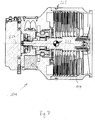
- Fig. 7 shows a cross section along in FIG Fig. 6 shown turbomolecular pump 111
- Fig. 8 shows a detail cross section of in Fig. 6 Turbomolecular pump 111 shown in the Fig. 7 and 8th
- the engagement structure 225 in the present embodiment is a groove-like depression with a T-shaped cross section 233.
- the engagement structure in this case has the projections 235, which can engage behind an introduced fastening element, such as a slot nut, in a form-fitting manner.
- the T-shaped cross section 233 can be interrupted by omitting the projections 235, so that a fastening element, such as a sliding block, can be introduced in a manner that facilitates handling.
- Fig. 9 shows a detail cross section of in Fig. 6 It can be seen that the fastening element 237 designed as a sliding block is inserted into the engagement structure 225 and engages in the projections 235 or the projections 235 in the fastening element 237 intervention.
- the fastening element 237 designed as a sliding block is thus connected in a form-fitting manner to the engagement structure 225.
- the fastening element 237 can be displaced along the course of the engagement structure 225, in particular along a circumferential orientation or circumferential direction of the pump body or of the housing 119, so that in the raised state of the vacuum pump 111, a handling-friendly rotation about the longitudinal axis 227 can take place.
- a load-receiving means 239 such as an eyebolt, can be screwed into the fastening element 237.
- the load-receiving means 239 can be used for connection to a suspension of a hoist or a separate stop means.
- Fig. 10 shows a cross section along in FIG Fig. 6 It can be seen that the fastening element 237 designed as a sliding block is inserted into the engagement structure 225 and a positive connection between the fastening element 237 and the engagement structure 225 is produced. At the same time, a load-receiving means 239 configured as an eyebolt is screwed into the fastening element 237, wherein a one-piece design of the components 237 and 239 is likewise possible. To the load-receiving means 239, a suspension means of a hoist or a separate stop means can be attached. Again Fig.
- the Fig. 11 shows a side view of a turbomolecular pump according to another embodiment of the invention.
- the in the Fig. 11 shown turbomolecular pump 111 has a total of two engagement structures 225, which also extend in the circumferential direction of the housing 119 at its outer periphery.
- each engagement structure 225 extends along a plane that is orthogonal to the longitudinal axis 227 of the housing 119 or the pump body of the turbomolecular pump 111.
- Each engagement structure 225 is in turn formed as a groove-like depression, in particular with a T-shape, and moreover has an insertion section 231 in which the T-shape is interrupted.
- the Fig. 11 It can also be seen that the center of gravity 229 of the pump body along the longitudinal axis 227 between the two engagement structures 225 is arranged.
- the two engagement structures 225 are therefore arranged axially on both sides of the center of gravity 229.
- the engagement structures 225 have different axial distances to the center of gravity 229. It is also possible that the axial distance of an engagement structure 225 to the center of gravity 229 with the axial distance of another engagement structure 225 to the center of gravity 229 matches ((quasi) equidistant arrangement), which is not shown here.
- the in the Fig. 6 to 11 The engagement structures 225 shown by way of example and the concepts generally described in the introduction to the description can also be used in the embodiments according to FIGS Fig. 1 to 5 be provided, although not shown or explained there in detail. This applies to all details regarding the arrangement and / or design of the engagement structure on the pump body or the pump housing 119 of the turbomolecular pump 111. Likewise, all or individual details of the in the Fig. 1 to 5 shown and described accordingly turbomolecular pump 111 also in the in the Fig. 6 to 11 shown embodiments of the turbomolecular pump 111 may be provided.
Landscapes
- Engineering & Computer Science (AREA)
- Mechanical Engineering (AREA)
- General Engineering & Computer Science (AREA)
- Non-Positive Displacement Air Blowers (AREA)
- Structures Of Non-Positive Displacement Pumps (AREA)
Abstract
Vakuumpumpe, insbesondere Turbomolekularpumpe, mit einem Pumpenkörper und einer daran ausgebildeten Befestigungsvorrichtung, die zumindest eine Eingriffsstruktur zur Verbindung eines Befestigungselements mit dem Pumpenkörper aufweist, wobei die Eingriffsstruktur am Außenumfang des Pumpenkörpers zumindest abschnittsweise unter einem Winkel zu dessen Längserstreckung verläuft, wobei eine Position und/oder Anordnung der Befestigungsvorrichtung entlang der Längserstreckung des Pumpenkörpers in Abhängigkeit des Gewichtsschwerpunkts des Pumpenkörpers gewählt ist.Vacuum pump, in particular turbomolecular pump, with a pump body and a fastening device formed thereon, which has at least one engagement structure for connecting a fastening element to the pump body, the engagement structure on the outer circumference of the pump body running at least in sections at an angle to its longitudinal extent, a position and / or Arrangement of the fastening device along the longitudinal extent of the pump body is selected depending on the center of gravity of the pump body.
Description
Die vorliegende Erfindung betrifft eine Vakuumpumpe, insbesondere eine Turbomolekularpumpe, sowie eine Anordnung und ein Verfahren zur Handhabung und/oder Montage einer Vakuumpumpe.The present invention relates to a vacuum pump, in particular a turbomolecular pump, and to an arrangement and a method for handling and / or mounting a vacuum pump.
Vakuumpumpen werden häufig in Anlagen eingesetzt, die eine waagerechte Befestigung der jeweiligen Vakuumpumpe erfordern. Dies gilt insbesondere für Turbomolekularpumpen in Saugvermögensklassen größer als 1000 l/s. Als Saugvermögen wird vorliegend der Volumenstrom angesehen, der pro Zeiteinheit durch eine Querschnittsfläche oder einen pumpwirksamen Abschnitt gefördert werden kann. Solche Pumpen können baugrößenbedingt ein hohes Eigengewicht aufweisen. Daher werden solche Pumpen üblicherweise nur mit einer Hebehilfe angehoben. Ebenso erfordert die Ausrichtung der Pumpe sowie deren Befestigung an einer jeweils vorgesehenen Anlage eine geeignete Hebehilfe.Vacuum pumps are often used in systems that require a horizontal mounting of the respective vacuum pump. This applies in particular to turbomolecular pumps in pumping capacity classes greater than 1000 l / s. In the present case, the volume flow which can be conveyed per unit time through a cross-sectional area or a pump-effective section is regarded as the pumping speed. Such pumps may have a high weight due to the size of the construction. Therefore, such pumps are usually raised only with a lifting aid. Similarly, the orientation of the pump and its attachment to a respective system requires a suitable lifting aid.
Aus dem Stand der Technik ist es bekannt, Pumpen mit einem hohen Eigengewicht durch Umlegen einer Schlaufe anzuheben. Dabei können Hebezeuge, wie zum Beispiel händisch zu betätigende Kräne, zum Einsatz kommen. Allerdings ist das Heben einer Pumpe mit Hilfe einer umgelegten Schlaufe riskant. So kann die Pumpe aus der Schlaufe herausrutschen und herunterfallen, wodurch schwere Schäden oder sogar Verletzungen entstehen können.From the prior art it is known to lift pumps with a high weight by flipping a loop. Hoists, such as manually operated cranes, can be used. However, lifting a pump with the help of a folded loop is risky. This will allow the pump to slip out of the loop and fall, causing serious damage or even injury.
Ferner ist es bekannt, in dem Gehäuse einer Pumpe zumindest ein Gewinde vorzusehen, in das eine Augenschraube eingeschraubt werden kann. Für den jeweiligen Hebe- und Montagevorgang kann dann ein Haken des Hebezeugs in die Augenschraube eingeklinkt werden. Hierdurch wird ein verhältnismäßig sicherer Hebevorgang gewährleistet. Für die Montage der Pumpe ist jedoch nicht nur das Anheben erforderlich, sondern auch die Ausrichtung der Pumpe im Raum. Dies kann bei einer fest vorgegebenen Lage der Augenschrauben am Gehäuse nur mit großen Schwierigkeiten bewerkstelligt werden. Insbesondere ist hierfür erheblicher manueller Krafteinsatz erforderlich, wodurch die beschädigungsfreie Montage der Pumpe in ihrer gewünschten Endstellung wiederum erschwert wird.Furthermore, it is known to provide at least one thread in the housing of a pump into which an eyebolt can be screwed. For the respective lifting and assembly process can then be a hook of the hoist in the eye bolt be latched. This ensures a relatively safe lifting operation. However, mounting the pump requires not only lifting, but also the orientation of the pump in the room. This can be accomplished at a fixed predetermined position of the eyebolts on the housing only with great difficulty. In particular, this considerable manual power input is required, whereby the damage-free installation of the pump in its desired end position is in turn difficult.
Vor diesem Hintergrund besteht eine Aufgabe der vorliegenden Erfindung darin, eine Vakuumpumpe anzugeben, die mit verringertem Handhabungsaufwand angehoben, ausgerichtet und/oder montiert werden kann. Ebenso besteht die Aufgabe darin, eine Anordnung sowie ein Verfahren zur Handhabung und/oder Montage einer Vakuumpumpe anzugeben.Against this background, an object of the present invention is to provide a vacuum pump, which can be raised, aligned and / or mounted with reduced handling costs. Likewise, the object is to provide an arrangement and a method for handling and / or mounting a vacuum pump.
Im Hinblick auf eine Vakuumpumpe ist diese Aufgabe mit den Merkmalen des Anspruchs 1 gelöst worden. Eine erfindungsgemäße Anordnung ist Gegenstand des Anspruchs 13 und ein erfindungsgemäßes Verfahren ist in Anspruch 14 angegeben. Vorteilhafte Ausgestaltungen sind in den abhängigen Ansprüchen spezifiziert und werden nachfolgend erörtert.With regard to a vacuum pump, this object has been achieved with the features of
Eine erfindungsgemäße Vakuumpumpe, bei der es sich insbesondere um eine Turbomolekularpumpe handeln kann, weist einen Pumpenkörper und eine daran ausgebildete Befestigungsvorrichtung auf, die zumindest eine Eingriffsstruktur zur Verbindung eines Befestigungselements mit dem Pumpenkörper aufweist. Bei dem Befestigungselement kann es sich beispielsweise um einen Nutenstein handeln (siehe hierzu z.B. DIN 508), der in die Eingriffsstruktur eingeführt wird und das Einschrauben einer sogenannten Augenschraube beziehungsweise Ringschraube (siehe hierzu z.B. DIN 580) ermöglicht. Erfindungsgemäß verläuft die Eingriffsstruktur am Außenumfang des Pumpenkörpers zumindest abschnittsweise unter einem Winkel zu dessen Längserstreckung. Die Eingriffsstruktur verläuft also nicht oder zumindest nicht genau entlang der Längserstreckung des Pumpenkörpers sondern unter einem Winkel zu dieser. Hierdurch wird ermöglicht, dass der Pumpenkörper im angehobenen Zustand um die Längserstreckung herum ausgerichtet wird, wenn ein Befestigungselement innerhalb der Eingriffsstruktur verschoben wird.A vacuum pump according to the invention, which may be in particular a turbomolecular pump, has a pump body and a fastening device formed thereon, which has at least one engagement structure for connecting a fastening element to the pump body. The fastening element can be, for example, a sliding block (see, for example, DIN 508), which is introduced into the engagement structure and allows the screwing in of a so-called eye bolt or eyebolt (see, for example, DIN 580). According to the invention, the engagement structure on the outer circumference of the pump body extends at least in sections at an angle to its longitudinal extent. The engagement structure thus runs not or at least not exactly along the longitudinal extent of the pump body but at an angle to this. This allows the pump body to be oriented in the raised state about the longitudinal extent when a fastener is displaced within the engagement structure.
Erfindungsgemäß ist nun vorgesehen, dass eine Position und/oder Anordnung der Befestigungsvorrichtung entlang der Längserstreckung, also in axialer Richtung, des Pumpenkörpers in Abhängigkeit des Gewichtsschwerpunkts des Pumpenkörpers gewählt ist. Durch Wahl der Position und/oder Anordnung der Befestigungsvorrichtung entlang der Längserstreckung des Pumpenkörpers in Abhängigkeit des Gewichtsschwerpunkts kann sichergestellt werden, dass die jeweils gewünschte Neigung des Pumpenkörpers im Raum auch mit nur geringem Kraftaufwand des jeweiligen Bedieners beibehalten werden kann. Die Handhabung und damit letztlich auch die Montage der Vakuumpumpe werden somit insgesamt erleichtert.According to the invention, it is now provided that a position and / or arrangement of the fastening device along the longitudinal extent, ie in the axial direction, of the pump body is selected as a function of the center of gravity of the pump body. By choosing the position and / or arrangement of the fastening device along the longitudinal extension of the pump body in dependence on the center of gravity can be ensured that the respectively desired inclination of the pump body in space can be maintained with little effort of the respective operator. The handling and thus ultimately the assembly of the vacuum pump are thus facilitated overall.
Erfindungsgemäß besteht demnach die Möglichkeit, ein Befestigungselement in oder an der Eingriffsstruktur anzuordnen, insbesondere in formschlüssiger Verbindung, um beispielsweise über eine Augenschraube eine Verbindung zu einem Hebezeug herzustellen. In angehobenem Zustand kann dann eine Rotation des Pumpenkörpers um die Längsachse herum bewerkstelligt werden, ohne dass die Aufrechterhaltung der Lage der Längsachse des Pumpenkörpers im Raum einen hohen Kraftaufwand erfordert. Dementsprechend einfach und ohne die Gefahr des Verkantens des jeweils eingesetzten Befestigungselements in oder an der Eingriffsstruktur kann die Rotationslage des Pumpenkörpers um die Längsachse oder Längserstreckung präzise eingestellt werden. Der gesamte Handhabungs- und Montageaufwand kann daher mit geringem manuellem Kraftaufwand erfolgen.According to the invention, there is thus the possibility of arranging a fastening element in or on the engagement structure, in particular in a positive connection, in order, for example, to establish a connection to a hoist via an eye bolt. In the raised state, a rotation of the pump body about the longitudinal axis can then be accomplished without the maintenance of the position of the longitudinal axis of the pump body in the room requires a lot of effort. Accordingly, easily and without the risk of tilting of the respectively used fastener in or on the engagement structure, the rotational position of the pump body about the longitudinal axis or longitudinal extent can be precisely adjusted. The entire handling and assembly effort can therefore be done with little manual effort.
In vorteilhafter Weise ist die Eingriffsstruktur zur verschiebbaren Führung eines Befestigungselements ausgebildet, insbesondere für eine verschiebbare Führung entlang einer Umfangsorientierung des Pumpenkörpers. Durch die verschiebbare Führung kann die Ausrichtung der Rotationslage des Pumpenkörpers in angehobenem Zustand einfach und ohne die Gefahr von Fehlbedienungen oder Verletzungen erfolgen. Insbesondere wird durch die verschiebbare Führung gewährleistet, dass während einer Rotation des Pumpenkörpers um die Längsachse und der damit einhergehenden Verschiebung eines Befestigungsmittels in oder an der Eingriffsstruktur das Befestigungsmittel nicht verkantet.Advantageously, the engagement structure is designed for the displaceable guidance of a fastening element, in particular for a displaceable guide along a circumferential orientation of the pump body. Due to the sliding guide, the orientation of the rotational position of the pump body in the raised state can be done easily and without the risk of incorrect operation or injury. In particular, it is ensured by the displaceable guide that during a rotation of the pump body about the longitudinal axis and the associated displacement of a fastening means in or on the engagement structure, the fastening means does not tilt.
Nach einer vorteilhaften Ausgestaltung verläuft die zumindest eine Eingriffsstruktur entlang einer Umfangsorientierung des Pumpenkörpers, insbesondere orthogonal oder im Wesentlichen orthogonal zur Längserstreckung des Pumpenkörpers. Auf diese Weise kann eine Ausrichtung des Pumpenkörpers um die Längsachse beziehungsweise um die Längserstreckung besonders handhabungsfreundlich vorgenommen werden.According to an advantageous embodiment, the at least one engagement structure extends along a circumferential orientation of the pump body, in particular orthogonal or substantially orthogonal to the longitudinal extension of the pump body. In this way, an alignment of the pump body about the longitudinal axis or about the longitudinal extent can be made particularly easy to handle.
Die Eingriffsstruktur kann den Außenumfang des Pumpenkörpers abschnittsweise oder auch vollständig umlaufen. Eine abschnittsweise vorgesehene Eingriffsstruktur ermöglicht dabei eine Ausrichtung zwischen zwei Grenzwinkellagen, so dass durch die Position der abschnittsweisen ausgebildeten Eingriffsstruktur eine Orientierungsvorgabe für die Endmontagestellung geschaffen werden kann. Bei einer vollständig umlaufenden Eingriffsstruktur lässt sich der Pumpenkörper im angehobenen Zustand vollständig um die eigene Längsachse drehen, so dass sämtliche Rotationslagen für die Endmontagestellung eingestellt werden können.The engagement structure may partially or completely circumscribe the outer circumference of the pump body. An engagement structure provided in sections permits alignment between two critical angle positions, so that an orientation specification for the final assembly position can be created by the position of the engagement structure formed in sections. In a fully encircling engagement structure, the pump body in the raised state can be completely rotated about its own longitudinal axis, so that all rotational positions can be adjusted for the final assembly position.
In vorteilhafter Weise umläuft die Eingriffsstruktur dabei den Außenumfang durchgehend. Dementsprechend ist die Eingriffsstruktur ringförmig in den Außenumfang des Pumpenkörpers eingebracht oder an diesem vorgesehen und damit endlos ausgebildet. Anfang und Ende der Eingriffsstruktur gehen in letzterer Ausgestaltung also nahtlos ineinander über.In an advantageous manner, the engagement structure runs around the outer circumference. Accordingly, the engagement structure is annularly introduced into the outer periphery of the pump body or provided on this and thus endless educated. The beginning and end of the intervention structure are thus seamlessly merged in the latter embodiment.
In besonders bevorzugter Weise ist die zumindest eine Eingriffsstruktur axial auf der Höhe des Gewichtsschwerpunkts des Pumpenkörpers positioniert. Dementsprechend ist die zumindest eine Eingriffsstruktur in Bezug auf die Längserstreckung oder Längsachse des Pumpenkörpers in einer Position angeordnet, die mit der Position des Gewichtsschwerpunkts des Pumpenkörpers entlang der Längserstreckung oder Längsachse übereinstimmt. Auf diese Weise kann mit nur einer Eingriffsstruktur eine handhabungsfreundliche Montage sichergestellt werden. So wird durch diese Anordnung der Eingriffsstruktur sichergestellt, dass ohne zusätzlichen Stützaufwand durch den Bediener eine im Wesentlichen waagerechte Ausrichtung des Pumpenkörpers in angehobenem Zustand der Vakuumpumpe beibehalten werden kann.In a particularly preferred manner, the at least one engagement structure is positioned axially at the height of the center of gravity of the pump body. Accordingly, the at least one engagement structure with respect to the longitudinal extent or longitudinal axis of the pump body is arranged in a position which coincides with the position of the center of gravity of the pump body along the longitudinal extent or longitudinal axis. In this way, a handling-friendly installation can be ensured with only one engagement structure. Thus, this arrangement of the engagement structure ensures that a substantially horizontal alignment of the pump body in the raised state of the vacuum pump can be maintained without additional support effort by the operator.
Gemäß einer vorteilhaften Ausgestaltung der erfindungsgemäßen Vakuumpumpe weist die Befestigungsvorrichtung eine Mehrzahl von Eingriffsstrukturen auf. Durch eine Mehrzahl von Eingriffsstrukturen lassen sich die Befestigungssicherheit für die jeweiligen Hebemittel und auch die Lagestabilität im angehobenen Zustand der Pumpe erhöhen.According to an advantageous embodiment of the vacuum pump according to the invention, the fastening device has a plurality of engagement structures. By a plurality of engagement structures, the fastening security for the respective lifting means and also the positional stability can be increased in the raised state of the pump.
Dabei sind in vorteilhafter Weise zumindest zwei Eingriffsstrukturen axial beidseitig des Gewichtsschwerpunkt des Pumpenkörpers positioniert. Insbesondere fassen die zwei Eingriffsstrukturen den Gewichtsschwerpunkt axial ein. Entlang der Längsachse des Pumpenkörpers gesehen ist somit eine Eingriffsstruktur vor dem Gewichtsschwerpunkt und eine weitere Eingriffsstruktur hinter dem Gewichtsschwerpunkt angeordnet. Ein unerwünschtes Neigen der Längsachse im Raum während des Anhebens und/oder des Montierens der Vakuumpumpe kann auf diese Weise sicher vermieden werden.In this case, at least two engagement structures are positioned axially on both sides of the center of gravity of the pump body in an advantageous manner. In particular, the two engagement structures axially grasp the center of gravity. Seen along the longitudinal axis of the pump body is thus arranged an engagement structure in front of the center of gravity and another engagement structure behind the center of gravity. An undesirable inclination of the longitudinal axis in space during lifting and / or mounting of the vacuum pump can be safely avoided in this way.
In besonders vorteilhafter Weise ist der axiale Abstand einer Eingriffsstruktur zum Gewichtsschwerpunkt mit dem axialen Abstand einer weiteren Eingriffsstruktur zum Gewichtsschwerpunkt übereinstimmend ausgewählt. Dies gewährleistet eine gleichmäßige Belastung der jeweils eingesetzten Lastaufnahme- beziehungsweise Anschlagmittel und/oder der jeweiligen Tragmittel des Hebezeugs. Ebenso ist es möglich, dass die Eingriffsstruktur unterschiedliche axiale Abstände zum Gewichtschwerpunkt aufweisen, wodurch eine größere Gestaltungsfreiheit bei der Wahl der Position der einzelnen Eingriffsstrukturen besteht.In a particularly advantageous manner, the axial distance of an engagement structure to the center of gravity is selected to coincide with the axial distance of a further engagement structure to the center of gravity. This ensures a uniform load on the respectively used load-receiving or lifting means and / or the respective suspension means of the hoist. It is also possible that the engagement structure have different axial distances to the center of gravity, whereby a greater freedom of design in the choice of the position of the individual engagement structures.
Weiter bevorzugt ist die Eingriffsstruktur als nutartige Vertiefung und/oder zur Aufnahme zumindest eines Nutensteins ausgebildet ist. Dabei kann bevorzugt ein Nutenstein innerhalb der nutartigen Vertiefung verschiebbar sein. Die Verwendung von Nutensteinen und die entsprechende Ausbildung der Eingriffsstruktur als nutartige Vertiefung erlaubt ein zeitsparendes und handhabungsfreundliches Anheben des Pumpenkörpers, da etwaige Nutensteine mit nur wenigen Handgriffen mit einer derartigen Eingriffsstruktur verbunden werden können. Bei der nutartigen Vertiefung handelt es sich bevorzugt um eine T-Nut. Dementsprechend weist die Nut im Querschnitt eine T-Form auf, wodurch in besonders einfacher Weise eine formschlüssige Kopplung mit einem Befestigungselement, das insbesondere als Nutenstein ausgebildet ist, erzeugt werden kann.More preferably, the engagement structure is designed as a groove-like depression and / or for receiving at least one sliding block. In this case, a sliding block may preferably be displaceable within the groove-like depression. The use of sliding blocks and the corresponding formation of the engagement structure as a groove-like recess allows a time-saving and handling-friendly lifting of the pump body, since any sliding blocks can be connected in only a few steps with such an engagement structure. The groove-like depression is preferably a T-slot. Accordingly, the groove has a T-shape in cross-section, whereby in a particularly simple manner a positive coupling with a fastening element, which is designed in particular as a sliding block, can be generated.
Ebenso kann es von Vorteil sein, wenn die zumindest eine Eingriffsstruktur als stegartiger Vorsprung und/oder zur Führung eines komplementär geformten Befestigungselements ausgebildet ist, insbesondere einem Nutenstein mit darin ausgebildeter nutartiger Vertiefung, die einen beispielsweise T-förmigen Steg umgreift. Solche stegartigen Vorsprünge können einfach gefertigt werden und gestatten ebenfalls eine sichere Befestigung und geeignete Führung für komplementär geformte Befestigungselemente.It may also be advantageous if the at least one engagement structure is designed as a web-like projection and / or for guiding a complementary shaped fastener, in particular a sliding block with formed therein groove-like depression which engages around an example T-shaped web. Such web-like projections can be easily manufactured and also allow a secure attachment and appropriate guidance for complementary shaped fasteners.
Weiterhin kann es von Vorteil sein, wenn die Eingriffsstruktur einen Einführabschnitt für ein Befestigungselement aufweist und/oder wobei der Einführabschnitt zum Einführen eines Befestigungselements quer zum Längsverlauf der Eingriffsstruktur ausgebildet ist. Somit kann das jeweilige Befestigungselement nur für die Durchführung der jeweiligen Handhabungs- und Montageaufgabe in die Eingriffsstruktur eingebracht oder an dieser verbindend angeordnet werden. Nach der Handhabungs- und Montageaufgabe kann das Befestigungselement wieder aus der Eingriffsstruktur entfernt und gegebenenfalls wiederverwendet werden.Furthermore, it may be advantageous if the engagement structure has an insertion section for a fastening element and / or wherein the insertion section for insertion of a fastening element is formed transversely to the longitudinal course of the engagement structure. Thus, the respective fastening element can only be introduced into the engagement structure for the implementation of the respective handling and assembly task or can be arranged to connect to it. After the handling and assembly task, the fastener can be removed again from the engagement structure and optionally reused.
Der Einführabschnitt kann durch eine Unterbrechung der Querschnittsform, insbesondere durch eine Unterbrechung eines T-förmigen Querschnitts und/oder durch Weglassen von Vorsprüngen zum formschlüssigen Hintergreifen eines Befestigungselements gebildet sein. Beispielsweise im Fall einer nutartigen Vertiefung kann der Einführabschnitt durch einen Nutabschnitt gebildet sein, der einen lediglich rechteckigen Querschnitt ohne Vorsprünge beziehungsweise ohne T-Form aufweist.The insertion section may be formed by an interruption of the cross-sectional shape, in particular by an interruption of a T-shaped cross section and / or by omitting projections for the form-fitting engagement of a fastening element. For example, in the case of a groove-like depression, the insertion section may be formed by a groove section which has a merely rectangular cross-section without projections or without a T-shape.
Bei Vorhandensein eines Einführabschnitts kann die Eingriffsstruktur in vorteilhafter Weise einen Vorsprung und/oder einen Absatz zur Verengung und/oder Verkleinung der Querschnittsfläche der Eingriffsstruktur aufweisen. Ein derartiger Vorsprung und/oder Absatz kann bevorzugt vor beziehungsweise hinter dem Einführabschnitt vorgesehen sein, beispielsweise durch einen Absatz in der Oberfläche der umlaufenden Eingriffsstruktur. Somit kann ein Nutenstein zwar lastfrei durch die Eingriffsstruktur geführt werden. Unter Last, also mit daran hängender Pumpe, ist jedoch eine gesondert zugeführte Gegenkraft oder ein leichtes Verkanten erforderlich, um die entsprechende Verengung zu überwinden. Eine solche Ausgestaltung beugt dem versehentlichen Verlust und einem ungewollten Sturz der hängenden Last bei Verschieben des Nutsteins in den Bereich eines Einführabschnitts vor.In the presence of an insertion section, the engagement structure may advantageously have a projection and / or a step for narrowing and / or reducing the cross-sectional area of the engagement structure. Such a projection and / or shoulder may preferably be provided in front of or behind the insertion section, for example by a shoulder in the surface of the circumferential engagement structure. Thus, a sliding block can indeed be guided without load through the engagement structure. However, under load, ie with a pump attached to it, a separately supplied opposing force or slight tilting is required in order to overcome the corresponding constriction. Such a design prevents the accidental loss and accidental fall of the hanging load when moving the sliding block in the region of an insertion.
Um den Fertigungsaufwand für eine erfindungsgemäße Eingriffsstruktur gering zu halten, kann diese durch Zerspanung erzeugt sein, bevorzugt durch Drehen und/oder Fräsen. Für den Fall der Ausbildung der Eingriffsstruktur als T-Nut ist bevorzugt ein T-Nuten Fräser zur Erzeugung einzusetzen, was kostengünstig zu bewerkstelligen ist.In order to keep the production costs low for an engagement structure according to the invention, this can be produced by machining, preferably by turning and / or milling. In the case of the formation of the engagement structure as a T-slot, it is preferable to use a T-slot milling cutter for production, which is inexpensive to accomplish.
Dabei kann die Eingriffsstruktur insbesondere durch spanende Bearbeitung des Pumpenkörpers in diesen eingebracht werden. Dementsprechend lässt sich beispielsweise ein Teil des Pumpenkörpers durch urformende und/oder umformende Verfahren in seiner Grundform erzeugen und anschließend die Eingriffsstruktur durch einen Zerspanungsprozess in den Außenumfang des Pumpenkörpers einbringen oder an diesem erzeugen. Dies kann mit nur geringem fertigungstechnischem Aufwand realisiert werden.In this case, the engagement structure can be introduced in particular by machining the pump body in this. Accordingly, for example, a part of the pump body can be produced by primary shaping and / or forming processes in its basic form and then introduce the engagement structure into the outer circumference of the pump body by means of a machining process or generate it. This can be realized with little manufacturing effort.
Gemäß einer vorteilhaften Ausgestaltung der erfindungsgemäßen Vakuumpumpe ist der Pumpenkörper gebildet durch ein Gehäuse sowie zumindest einer in und/oder an dem Gehäuse angeordneten Pumpenkomponente. Insbesondere ist eine Mehrzahl von Pumpenkomponenten in und/oder an dem Gehäuse angeordnet. Da der Gewichtsschwerpunkt des gesamten Pumpenkörpers, welcher das Gehäuse sowie die zumindest eine Pumpenkomponente einschließt, maßgeblich ist für die Position und/oder Anordnung der Befestigungsvorrichtung, kann auch die Balance des gesamten Pumpenkörpers in angehobenem Zustand mit besonders geringem manuellen Krafteinsatz aufrecht erhalten werden. Insbesondere kann hierdurch vermieden werden, dass einzelne Komponenten der Vakuumpumpe im angehobenen Zustand ein Ungleichgewicht schaffen, wodurch sich in angehobener Stellung die Neigung der Längsachse im Raum ungünstig oder in unerwünschter Weise einstellt.According to an advantageous embodiment of the vacuum pump according to the invention, the pump body is formed by a housing and at least one pump component arranged in and / or on the housing. In particular, a plurality of pump components is arranged in and / or on the housing. Since the center of gravity of the entire pump body, which includes the housing and the at least one pump component, is decisive for the position and / or arrangement of the fastening device, and the balance of the entire pump body in the raised state with very little manual force application can be maintained. In particular, this can be avoided that individual components of the vacuum pump create an imbalance in the raised state, which adjusts the inclination of the longitudinal axis in the room unfavorable or undesirable in the raised position.
In vorteilhafter Weise kann das Gehäuse der Vakuumpumpe mehrteilig ausgebildet werden, wodurch die Montage der Einzelteile der Pumpe vereinfacht beziehungsweise der konstruktive Gestaltungsspielraum vergrößert wird.Advantageously, the housing of the vacuum pump can be formed in several parts, whereby the assembly of the individual parts of the pump simplified or the structural design freedom is increased.
Zumindest eine Pumpenkomponente kann als Rotor ausgebildet sein und das Gehäuse kann einen Stator bilden oder mit einem Stator verbunden sein, wodurch eine platzsparende Konstruktion gewährleistet wird. In weiter bevorzugter Weise ist der Rotor der Vakuumpumpe um eine Rotationsachse drehend gelagert, die entlang der Längserstreckung des Pumpenkörpers und/oder durch dessen Gewichtsschwerpunkt verläuft, insbesondere mit einer Schwerachse des Pumpenkörpers zusammenfällt. Durch eine solche Anordnung kann in besonders einfacher Weise eine Ausrichtung des Pumpenkörpers um die Rotationsachse des Rotors erfolgen. Der jeweilige Pumpeneinlass oder -auslass der Vakuumpumpe kann somit in einfacher Weise an die jeweiligen Anlagen ausgerichtet werden, um anschließend die erforderlichen Montagearbeiten durchzuführen.At least one pump component may be formed as a rotor and the housing may form a stator or be connected to a stator, whereby a space-saving construction is ensured. In a further preferred manner, the rotor of the vacuum pump is rotatably mounted about an axis of rotation which runs along the longitudinal extent of the pump body and / or through its center of gravity, in particular coincides with a gravity axis of the pump body. Such an arrangement makes it possible to align the pump body about the axis of rotation of the rotor in a particularly simple manner. The respective pump inlet or outlet of the vacuum pump can thus be aligned in a simple manner to the respective equipment, in order subsequently to carry out the necessary assembly work.
Gemäß einer vorteilhaften Ausgestaltung der erfindungsgemäßen Vakuumpumpe weist das Gehäuse eine Längserstreckung und/oder einen rechteckigen und/oder im Wesentlichen runden Außenumfang auf, bevorzugt einen kreisrunden Außenumfang. Auf diese Weise lassen sich die jeweiligen Pumpenkomponenten mit nur geringem Bauraum innerhalb eines kompakten Gehäuses unterbringen. Für den Fall eines runden Außenumfangs kann der jeweilige Pumpenrotor platzsparend in einem als Stator ausgebildeten Gehäuse untergebracht werden.According to an advantageous embodiment of the vacuum pump according to the invention, the housing has a longitudinal extension and / or a rectangular and / or substantially round outer periphery, preferably a circular outer periphery. In this way, the respective pump components can be accommodated within a compact housing with only a small space. In the case of a round outer periphery of the respective pump rotor can be accommodated in a space-saving designed as a stator housing.
Weiterhin kann es von Vorteil sein, wenn die Längserstreckung des Gehäuses größer ist als ein Gehäusedurchmesser, insbesondere als ein mittlerer und/oder als der größte oder kleinste Gehäusedurchmesser. In diesem Fall hat das Gehäuse insgesamt eine längliche Ausprägung, wodurch eine Mehrzahl von Pumpstufen beziehungsweise Rotoren in dem Gehäuse angeordnet werden können und damit eine hohe Pumpenleistung erzielt werden kann.Furthermore, it may be advantageous if the longitudinal extent of the housing is greater than a housing diameter, in particular as a middle and / or as the largest or smallest housing diameter. In this case, the housing has an overall elongated shape, whereby a plurality of pumping stages or rotors can be arranged in the housing and thus a high pumping capacity can be achieved.
In weiter vorteilhafter Weise kann der Pumpenkörper, insbesondere das Gehäuse der Pumpe, angrenzend an die zumindest eine Eingriffsstruktur eine Verstärkung aufweisen. Durch eine solche Verstärkung kann die Befestigungsstabilität erhöht werden. Insbesondere kann hierdurch vermieden werden, dass sich ein Befestigungselement durch unerwünschte Verformung der an die Eingriffsstruktur angrenzenden Bereiche des Pumpenkörpers verformt und dadurch aus der Eingriffsstruktur herausgelöst wird. Die Gefahr des Herunterfallens der Pumpe wird somit verringert. Eine derartige Verstärkung des Pumpenkörpers kann dadurch erreicht werden, dass im Bereich der und/oder angrenzend an die Eingriffsstruktur eine größere Wandstärke vorgesehen ist als in den übrigen Pumpenkörperabschnitten, insbesondere Gehäuseabschnitten.In a further advantageous manner, the pump body, in particular the housing of the pump, adjacent to the at least one engagement structure have a gain. By such a reinforcement, the attachment stability can be increased. In particular, this can be avoided that a fastener is deformed by undesirable deformation of the adjoining the engagement structure areas of the pump body and thereby dissolved out of the engagement structure. The risk of falling of the pump is thus reduced. Such a reinforcement of the pump body can be achieved by providing a greater wall thickness in the region of and / or adjacent to the engagement structure than in the remaining pump body sections, in particular housing sections.
Gemäß einem weiteren Aspekt der vorliegenden Erfindung ist eine Anordnung zur Handhabung und/oder Montage einer Vakuumpumpe vorgesehen, mit einem ein Tragmittel aufweisendes Hebewerkzeug sowie mit einer voranstehend beschriebenen Vakuumpumpe. Ferner ist zumindest ein in oder an der Eingriffsstruktur (z.B. eine Nut oder ein Steg) verschiebbar positioniertes Befestigungselement, bevorzugt ein Nutenstein, sowie ein Lastaufnahmemittel vorgesehen, das mit dem Befestigungselement verbunden oder einstückig ausgebildet und bevorzugt als Augenschraube ausgebildet ist. Dabei ist das Lastaufnahmemittel bevorzugt mit dem Tragemittel verbunden, entweder direkt oder indirekt über ein Anschlagmittel, beispielsweise in Form eines Trage- oder Hebegurts.According to a further aspect of the present invention, there is provided an arrangement for handling and / or assembling a vacuum pump, comprising a lifting tool having a carrying means and having a vacuum pump as described above. Furthermore, at least one fastening element displaceably positioned in or on the engagement structure (for example a groove or a web), preferably a sliding block, and a load receiving means are provided which are connected or integrally formed with the fastening element and are preferably designed as eyebolts. In this case, the load-receiving means is preferably connected to the support means, either directly or indirectly via a stop means, for example in the form of a carrying or sling.
Durch eine derartige Anordnung lässt sich eine voranstehend beschriebene Vakuumpumpe mit geringem Aufwand und mit einem hohen Maß an Sicherheit anheben, handhaben und schließlich in der gewünschten Endstellung an der jeweiligen Anlage montieren. Im angehobenen Zustand kann mit nur geringem manuellen Krafteinsatz eine Rotation des Pumpenkörpers um die Längserstreckung beziehungsweise Längsachse vorgenommen und somit die gewünschte Ausrichtung beziehungsweise Rotationslage des Pumpenkörpers im Raum eingestellt werden, wobei hierzu das Befestigungselement z.B. in einer nutartigen Vertiefung oder an einem Vorsprung des Pumpenkörpers verschiebbar angeordnet ist und somit die Rotationsbewegung während der Handhabung unterstützt.By such an arrangement, a vacuum pump described above can be raised with little effort and with a high degree of security, handle and finally mounted in the desired end position to the respective system. In the raised state, a rotation of the pump body about the longitudinal extension or longitudinal axis can be made with only a slight manual application of force and thus the desired orientation or rotation position of the pump body are set in space, for this purpose, the fastener is arranged displaceably, for example, in a groove-like depression or on a projection of the pump body and thus supports the rotational movement during handling.
Ein weiterer Aspekt der vorliegenden Erfindung betrifft ein Verfahren zur Handhabung und/oder Montage einer Vakuumpumpe, bevorzugt einer voranstehend beschriebenen Vakuumpumpe. Bevorzugt lässt sich ein solches Verfahren mit einer voranstehend beschriebenen Anordnung vornehmen. Dabei wird erfindungsgemäß die Vakuumpumpe durch ein Hebezeug angehoben, anschließend durch Rotation um eine Längs- und/oder Rotorachse im Raum ausgerichtet, wobei durch die Rotation der Vakuumpumpe im Raum zumindest ein Befestigungselement, bevorzugt ein Nutenstein, an und/oder in der Eingriffsstruktur der Vakuumpumpe geführt verschoben wird. Durch die geführte Verschiebung des Befestigungselements wird eine kontrollierte Rotation des Pumpenkörpers um die Längsachse ermöglicht, so dass eine präzise Ausrichtung im Raum mit nur geringem manuellem Kraftaufwand sichergestellt werden kann.Another aspect of the present invention relates to a method for handling and / or mounting a vacuum pump, preferably a vacuum pump described above. Preferably, such a method can be carried out with a previously described arrangement. In this case, according to the invention, the vacuum pump lifted by a hoist, then aligned by rotation about a longitudinal and / or rotor axis in space, wherein by the rotation of the vacuum pump in space at least one fastener, preferably a sliding block, on and / or in the engagement structure of the vacuum pump is moved led. The guided displacement of the fastener allows a controlled rotation of the pump body about the longitudinal axis, so that precise alignment in space can be ensured with little manual effort.
Gemäß einem weiteren Aspekt der vorliegenden Erfindung ist der Einführabschnitt als abzweigende Nut zur umlaufenden Eingriffsstruktur ausgebildet, insbesondere in Form eines Einführkanals. Ein solcher Einführkanal kann zum Beispiel an einer Stirnseite des Pumpenkörpers austreten und/oder in einem zur Eingriffstruktur axial versetzten Einführabschnitt münden. Ein Lastaufnahmemittel kann entweder direkt axial eingeschoben oder durch Eintauchen eingesetzt werden.According to a further aspect of the present invention, the insertion section is formed as a branching groove to the circumferential engagement structure, in particular in the form of an insertion channel. Such an insertion channel can emerge, for example, on an end face of the pump body and / or open into an insertion section axially offset from the engagement structure. A load handling device can either be inserted directly axially or inserted by immersion.
Bei Vorsehen eines derartigen Einführkanals kann die umlaufende Positionierbarkeit des Lastaufnahmemittels entlang der umlaufenden Eingriffsstruktur ohne Unterbrechung erfolgen, da ein Herausfallen des Lastaufnahmemittels aus dem axial versetzten Einführabschnitt vermieden wird. Gleichzeitig kann die Herstellung der Eingriffsstruktur vereinfachen werden, da diese in einem rein umlaufend spanenden Prozess, beispielsweise durch Drehen gefertigt werden kann. Absätze in der Kontur der Eingriffsstruktur, die einen ungewollten Verlust des Lastaufnahmemittels am Einführabschnitts und damit den Sturz der Pumpe verhindern sollen, können weggelassen werden. Ferner kann ein etwaiger Einführkanal in vorteilhafter Weise durch die Stirnseite des Pumpenkörpers hindurch mit einem Werkzeug in nur einem Vorgang und ohne kompliziertes axiales Eintauchen des Werkzeugs hergestellt werden.When providing such an insertion channel, the circumferential positionability of the load receiving means along the circumferential engagement structure can be carried out without interruption, since falling out of the load receiving means is avoided from the axially offset insertion section. At the same time, the production of the engagement structure can be simplified, since they are machined in a purely circumferential manner Process, for example, can be made by turning. Paragraphs in the contour of the engagement structure, which should prevent an unwanted loss of the load-receiving means at the insertion and thus the fall of the pump, can be omitted. Further, any insertion channel can be advantageously made through the face of the pump body with a tool in one operation and without complicated axial dipping of the tool.
Bei einer Mehrzahl von Eingriffsstrukturen kann ein Einführkanal durch eine Eingriffsstruktur hindurch zu einer weiteren Eingriffsstruktur fortgeführt werden oder auch mehrere Einführkänale jeweils von verschiedenen Richtungen zu den Eingriffstrukturen geführt werden. Ein solcher Einführkanal kann ferner in verschiedenen Winkeln zur Pumpenlängsachse angeordnet sein beziehungsweise durch Versetzungen oder Winkel so gestaltet werden, dass er vorteilhaft das Verlieren beziehungsweise ungewollte Herauswandern von Lastaufnahmemitteln erschwert oder verhindert.In the case of a plurality of engagement structures, an insertion channel can be continued through an engagement structure to form a further engagement structure, or a plurality of insertion channels can each be guided from different directions to the engagement structures. Such an insertion channel may also be arranged at different angles to the pump longitudinal axis or be designed by dislocations or angles so that it advantageously impedes the loss or unwanted migration of load-receiving means or prevented.
Ein Einführkanal kann innerhalb nur eines Bestandteils des Pumpenkörpers ausgebildet sein, so dass vor Zusammensetzen der Bestandteile, beispielsweise dem Unterteil und dem Gehäuse ein Einführen des Lastaufnahmemittels möglich ist. Ein solcher Einführkanal kann nach Fügen der Bestandteile durch das jeweils angrenzende Teil überdeckt oder blockiert sein, so dass das Lastaufnahmemittel nicht herausnehmbar und damit unverlierbar dauerhaft in der Eingriffsstruktur beweglich eingesetzt bleibt. Eine solche Blockade des Einführabschnitts oder Einführkanals ist auch durch das Einsetzen, Einpressen, Einkleben und/oder das einmalige und/oder dauerhafte Befestigen eines Blockiermittels in den Einführabschnitt oder Einführkanal möglich.An insertion channel can be formed within only one component of the pump body, so that prior to assembly of the components, for example, the lower part and the housing, insertion of the load-receiving means is possible. Such an insertion channel may be covered or blocked after joining the components by the respectively adjacent part, so that the load-receiving means is not removable and thus remains permanently inserted into the engagement structure movable. Such a blockage of the insertion or insertion channel is also possible by the insertion, pressing, gluing and / or the unique and / or permanent attachment of a blocking agent in the insertion or insertion.
Die voranstehenden Ausführungen zu der erfindungsgemäßen Vakuumpumpe geltend entsprechend auch für die erfindungsgemäße Anordnung sowie das Verfahren zum Handhaben und/oder Montieren einer Vakuumpumpe.The above statements on the vacuum pump according to the invention also apply correspondingly to the arrangement according to the invention and to the method for handling and / or mounting a vacuum pump.
Nachfolgend wird die Erfindung beispielhaft anhand vorteilhafter Ausführungsformen unter Bezugnahme auf die beigefügten Figuren beschrieben. Es zeigen, jeweils schematisch:
- Fig. 1
- eine perspektivische Ansicht einer Turbomolekularpumpe,
- Fig. 2
- eine Ansicht der Unterseite der Turbomolekularpumpe von
Fig. 1 , - Fig. 3
- einen Querschnitt der Turbomolekularpumpe längs der in
Fig. 2 gezeigten Schnittlinie A-A, - Fig. 4
- eine Querschnittsansicht der Turbomolekularpumpe längs der in
Fig. 2 gezeigten Schnittlinie B-B, - Fig. 5
- eine Querschnittsansicht der Turbomolekularpumpe längs der in
Fig. 2 gezeigten Schnittlinie C-C, - Fig. 6
- eine Seitenansicht einer Turbomolekularpumpe gemäß einer Ausführungsform der Erfindung,
- Fig. 7
- einen Querschnitt längs der in
Fig. 6 gezeigten Turbomolekularpumpe, - Fig. 8
- einen Detailquerschnitt der in
Fig. 6 gezeigten Turbomolekularpumpe, - Fig. 9
- einen Detailquerschnitt der in
Fig. 6 gezeigten Turbomolekularpumpe mit eingefügten Nutenstein und befestigter Augenschraube, - Fig. 10
- einen Querschnitt längs der in
Fig. 6 gezeigten Turbomolekularpumpe mit eingefügtem Nutenstein und befestigter Augenschraube, - Fig. 11
- eine Seitenansicht einer Turbomolekularpumpe gemäß einer weiteren Ausführungsform der Erfindung.
- Fig. 1
- a perspective view of a turbomolecular pump,
- Fig. 2
- a view of the bottom of the turbomolecular pump from
Fig. 1 . - Fig. 3
- a cross section of the turbomolecular pump along in
Fig. 2 shown section line AA, - Fig. 4
- a cross-sectional view of the turbomolecular pump along in
Fig. 2 shown section line BB, - Fig. 5
- a cross-sectional view of the turbomolecular pump along in
Fig. 2 shown section line CC, - Fig. 6
- a side view of a turbomolecular pump according to an embodiment of the invention,
- Fig. 7
- a cross section along in
Fig. 6 shown turbomolecular pump, - Fig. 8
- a detail cross section of in
Fig. 6 shown turbomolecular pump, - Fig. 9
- a detail cross section of in
Fig. 6 shown turbomolecular pump with inserted sliding block and attached eyebolt, - Fig. 10
- a cross section along in
Fig. 6 shown turbomolecular pump with inserted sliding block and attached eyebolt, - Fig. 11
- a side view of a turbomolecular pump according to another embodiment of the invention.
Die in
Der Einlassflansch 113 bildet bei der Ausrichtung der Vakuumpumpe gemäß
Am Gehäuse 119 der Turbomolekularpumpe 111 ist ein Fluteinlass 133, insbesondere in Form eines Flutventils, vorgesehen, über den die Vakuumpumpe 111 geflutet werden kann. Im Bereich des Unterteils 121 ist ferner noch ein Sperrgasanschluss 135, der auch als Spülgasanschluss bezeichnet wird, angeordnet, über welchen Spülgas zum Schutz des Elektromotors 125 vor dem von der Pumpe geförderten Gas in den Motorraum 137, in welchem der Elektromotor 125 in der Vakuumpumpe 111 untergebracht ist, gebracht werden kann. Im Unterteil 121 sind ferner noch zwei Kühlmittelanschlüsse 139 angeordnet, wobei einer der Kühlmittelanschlüsse als Einlass und der andere Kühlmittelanschluss als Auslass für Kühlmittel vorgesehen ist, das zu Kühlzwecken in die Vakuumpumpe geleitet werden kann.On the
Die untere Seite 141 der Vakuumpumpe kann als Standfläche dienen, sodass die Vakuumpumpe 111 auf der Unterseite 141 stehend betrieben werden kann. Die Vakuumpumpe 111 kann aber auch über den Einlassflansch 113 an einem Rezipienten befestigt werden und somit gewissermaßen hängend betrieben werden. Außerdem kann die Vakuumpumpe 111 so gestaltet sein, dass sie auch in Betrieb genommen werden kann, wenn sie auf andere Weise ausgerichtet ist als in
An der Unterseite 141, die in
An der Unterseite 141 sind außerdem Befestigungsbohrungen 147 angeordnet, über welche die Pumpe 111 beispielsweise an einer Auflagefläche befestigt werden kann.On the bottom 141 also mounting
In den
Wie die Schnittdarstellungen der
In dem Gehäuse 119 ist ein Rotor 149 angeordnet, der eine um eine Rotationsachse 151 drehbare Rotorwelle 153 aufweist.In the
Die Turbomolekularpumpe 111 umfasst mehrere pumpwirksam miteinander in Serie geschaltete turbomolekulare Pumpstufen mit mehreren an der Rotorwelle 153 befestigten radialen Rotorscheiben 155 und zwischen den Rotorscheiben 155 angeordneten und in dem Gehäuse 119 festgelegten Statorscheiben 157. Dabei bilden eine Rotorscheibe 155 und eine benachbarte Statorscheibe 157 jeweils eine turbomolekulare Pumpstufe. Die Statorscheiben 157 sind durch Abstandsringe 159 in einem gewünschten axialen Abstand zueinander gehalten.
Die Vakuumpumpe umfasst außerdem in radialer Richtung ineinander angeordnete und pumpwirksam miteinander in Serie geschaltete Holweck-Pumpstufen. Der Rotor der Holweck-Pumpstufen umfasst eine an der Rotorwelle 153 angeordnete Rotornabe 161 und zwei an der Rotornabe 161 befestigte und von dieser getragene zylindermantelförmige Holweck-Rotorhülsen 163, 165, die koaxial zur Rotationsachse 151 orientiert und in radialer Richtung ineinander geschachtelt sind. Ferner sind zwei zylindermantelförmige Holweck-Statorhülsen 167, 169 vorgesehen, die ebenfalls koaxial zu der Rotationsachse 151 orientiert und in radialer Richtung gesehen ineinander geschachtelt sind.The vacuum pump further comprises Holweck pumping stages which are arranged one inside the other in the radial direction and which are pumpingly connected to one another in series. The rotor of the Holweck pump stages comprises a
Die pumpaktiven Oberflächen der Holweck-Pumpstufen sind durch die Mantelflächen, also durch die radialen Innen- und/oder Außenflächen, der Holweck-Rotorhülsen 163, 165 und der Holweck-Statorhülsen 167, 169 gebildet. Die radiale Innenfläche der äußeren Holweck-Statorhülse 167 liegt der radialen Außenfläche der äußeren Holweck-Rotorhülse 163 unter Ausbildung eines radialen Holweck-Spalts 171 gegenüber und bildet mit dieser die der Turbomolekularpumpen nachfolgende erste Holweck-Pumpstufe. Die radiale Innenfläche der äußeren Holweck-Rotorhülse 163 steht der radialen Außenfläche der inneren Holweck-Statorhülse 169 unter Ausbildung eines radialen Holweck-Spalts 173 gegenüber und bildet mit dieser eine zweite Holweck-Pumpstufe. Die radiale Innenfläche der inneren Holweck-Statorhülse 169 liegt der radialen Außenfläche der inneren Holweck-Rotorhülse 165 unter Ausbildung eines radialen Holweck-Spalts 175 gegenüber und bildet mit dieser die dritte Holweck-Pumpstufe.The pump-active surfaces of the Holweck pump stages are formed by the lateral surfaces, ie by the radial inner and / or outer surfaces, the
Am unteren Ende der Holweck-Rotorhülse 163 kann ein radial verlaufender Kanal vorgesehen sein, über den der radial außenliegende Holweck-Spalt 171 mit dem mittleren Holweck-Spalt 173 verbunden ist. Außerdem kann am oberen Ende der inneren Holweck-Statorhülse 169 ein radial verlaufender Kanal vorgesehen sein, über den der mittlere Holweck-Spalt 173 mit dem radial innenliegenden Holweck-Spalt 175 verbunden ist. Dadurch werden die ineinander geschachtelten Holweck-Pumpstufen in Serie miteinander geschaltet. Am unteren Ende der radial innenliegenden Holweck-Rotorhülse 165 kann ferner ein Verbindungskanal 179 zum Auslass 117 vorgesehen sein.At the lower end of the
Die vorstehend genannten pumpaktiven Oberflächen der Holweck-Statorhülsen 163, 165 weisen jeweils mehrere spiralförmig um die Rotationsachse 151 herum in axialer Richtung verlaufende Holweck-Nuten auf, während die gegenüberliegenden Mantelflächen der Holweck-Rotorhülsen 163, 165 glatt ausgebildet sind und das Gas zum Betrieb der Vakuumpumpe 111 in den Holweck-Nuten vorantreiben.The above-mentioned pump-active surfaces of the
Zur drehbaren Lagerung der Rotorwelle 153 sind ein Wälzlager 181 im Bereich des Pumpenauslasses 117 und ein Permanentmagnetlager 183 im Bereich des Pumpeneinlasses 115 vorgesehen.For rotatably supporting the
Im Bereich des Wälzlagers 181 ist an der Rotorwelle 153 eine konische Spritzmutter 185 mit einem zu dem Wälzlager 181 hin zunehmenden Außendurchmesser vorgesehen. Die Spritzmutter 185 steht mit mindestens einem Abstreifer eines Betriebsmittelspeichers in gleitendem Kontakt. Der Betriebsmittelspeicher umfasst mehrere aufeinander gestapelte saugfähige Scheiben 187, die mit einem Betriebsmittel für das Wälzlager 181, z.B. mit einem Schmiermittel, getränkt sind.In the area of the
Im Betrieb der Vakuumpumpe 111 wird das Betriebsmittel durch kapillare Wirkung von dem Betriebsmittelspeicher über den Abstreifer auf die rotierende Spritzmutter 185 übertragen und in Folge der Zentrifugalkraft entlang der Spritzmutter 185 in Richtung des größer werdenden Außendurchmessers der Spritzmutter 92 zu dem Wälzlager 181 hin gefördert, wo es z.B. eine schmierende Funktion erfüllt. Das Wälzlager 181 und der Betriebsmittelspeicher sind durch einen wannenförmigen Einsatz 189 und den Lagerdeckel 145 in der Vakuumpumpe eingefasst.During operation of the
Das Permanentmagnetlager 183 umfasst eine rotorseitige Lagerhälfte 191 und eine statorseitige Lagerhälfte 193, welche jeweils einen Ringstapel aus mehreren in axialer Richtung aufeinander gestapelten permanentmagnetischen Ringen 195, 197 umfassen. Die Ringmagnete 195, 197 liegen einander unter Ausbildung eines radialen Lagerspalts 199 gegenüber, wobei die rotorseitigen Ringmagnete 195 radial außen und die statorseitigen Ringmagnete 197 radial innen angeordnet sind. Das in dem Lagerspalt 199 vorhandene magnetische Feld ruft magnetische Abstoßungskräfte zwischen den Ringmagneten 195, 197 hervor, welche eine radiale Lagerung der Rotorwelle 153 bewirken. Die rotorseitigen Ringmagnete 195 sind von einem Trägerabschnitt 201 der Rotorwelle 153 getragen, welcher die Ringmagnete 195 radial außenseitig umgibt. Die statorseitigen Ringmagnete 197 sind von einem statorseitigen Trägerabschnitt 203 getragen, welcher sich durch die Ringmagnete 197 hindurch erstreckt und an radialen Streben 205 des Gehäuses 119 aufgehängt ist. Parallel zu der Rotationsachse 151 sind die rotorseitigen Ringmagnete 195 durch ein mit dem Trägerabschnitt 203 gekoppeltes Deckelelement 207 festgelegt. Die statorseitigen Ringmagnete 197 sind parallel zu der Rotationsachse 151 in der einen Richtung durch einen mit dem Trägerabschnitt 203 verbundenen Befestigungsring 209 sowie einen mit dem Trägerabschnitt 203 verbundenen Befestigungsring 211 festgelegt. Zwischen dem Befestigungsring 211 und den Ringmagneten 197 kann außerdem eine Tellerfeder 213 vorgesehen sein.The
Innerhalb des Magnetlagers ist ein Not- beziehungsweise Fanglager 215 vorgesehen, welches im normalen Betrieb der Vakuumpumpe 111 ohne Berührung leer läuft und erst bei einer übermäßigen radialen Auslenkung des Rotors 149 relativ zu dem Stator in Eingriff gelangt, um einen radialen Anschlag für den Rotor 149 zu bilden, da eine Kollision der rotorseitigen Strukturen mit den statorseitigen Strukturen verhindert wird. Das Fanglager 215 ist als ungeschmiertes Wälzlager ausgebildet und bildet mit dem Rotor 149 und/oder dem Stator einen radialen Spalt, welcher bewirkt, dass das Fanglager 215 im normalen Pumpbetrieb außer Eingriff ist. Die radiale Auslenkung, bei der das Fanglager 215 in Eingriff gelangt, ist groß genug bemessen, sodass das Fanglager 215 im normalen Betrieb der Vakuumpumpe nicht in Eingriff gelangt, und gleichzeitig klein genug, sodass eine Kollision der rotorseitigen Strukturen mit den statorseitigen Strukturen unter allen Umständen verhindert wird.Within the magnetic bearing an emergency or catch bearing 215 is provided, which runs empty during normal operation of the
Die Vakuumpumpe 111 umfasst den Elektromotor 125 zum drehenden Antreiben des Rotors 149. Der Anker des Elektromotors 125 ist durch den Rotor 149 gebildet, dessen Rotorwelle 153 sich durch den Motorstator 217 hindurch erstreckt. Auf den sich durch den Motorstator 217 hindurch erstreckenden Abschnitt der Rotorwelle 153 kann radial außenseitig oder eingebettet eine Permanentmagnetanordnung angeordnet sein. Zwischen dem Motorstator 217 und dem sich durch den Motorstator 217 hindurch erstreckenden Abschnitt des Rotors 149 ist ein Zwischenraum 219 angeordnet, welcher einen radialen Motorspalt umfasst, über den sich der Motorstator 217 und die Permanentmagnetanordnung zur Übertragung des Antriebsmoments magnetisch beeinflussen können.The
Der Motorstator 217 ist in dem Gehäuse innerhalb des für den Elektromotor 125 vorgesehenen Motorraums 137 festgelegt. Über den Sperrgasanschluss 135 kann ein Sperrgas, das auch als Spülgas bezeichnet wird, und bei dem es sich beispielsweise um Luft oder um Stickstoff handeln kann, in den Motorraum 137 gelangen. Über das Sperrgas kann der Elektromotor 125 vor Prozessgas, z.B. vor korrosiv wirkenden Anteilen des Prozessgases, geschützt werden. Der Motorraum 137 kann auch über den Pumpenauslass 117 evakuiert werden, d.h. im Motorraum 137 herrscht zumindest annäherungsweise der von der am Pumpenauslass 117 angeschlossenen Vorvakuumpumpe bewirkte Vakuumdruck.The
Zwischen der Rotornabe 161 und einer den Motorraum 137 begrenzenden Wandung 221 kann außerdem eine sog. und an sich bekannte Labyrinthdichtung 223 vorgesehen sein, insbesondere um eine bessere Abdichtung des Motorraums 217 gegenüber den radial außerhalb liegenden Holweck-Pumpstufen zu erreichen.Between the
Die Turbomolekularpumpe der
Erfindungsgemäß ist nun die Position der Eingriffsstruktur 225 entlang der Längsachse 227 des Gehäuses 119 in Abhängigkeit eines Gewichtsschwerpunkts 229 des Pumpenkörpers der Turbomolekularpumpe 111 gewählt. Dabei bestimmt sich der Gewichtsschwerpunkt nach sämtlichen Bauteilen der Turbomolekularpumpe 111, nämlich insbesondere dem Pumpengehäuse 119 sowie sämtlichen in und an dem Gehäuse 119 angeordneten Pumpenkomponenten, insbesondere in der bei einer Montage der Pumpe 111 an einem Rezipienten vorliegenden Konfiguration. Auf diese Weise kann die Turbomolekularpumpe 111 in besonders vorteilhafter Weise über ein Befestigungselement in der Eingriffsstruktur 225 angehoben werden und in angehobener Stellung durch Rotation um die Längsachse 227 ausgerichtet werden, ohne dass zur Aufrechterhaltung der jeweils gewünschten Neigungslage der Längsachse 227 im Raum ein besonderer Kraftaufwand des Bedieners erforderlich ist.According to the invention, the position of the
Zum Einbringen eines Befestigungsmittels in die Eingriffsstruktur 225 kann die Eingriffsstruktur 225 mit einem Einführabschnitt 231 ausgestattet sein. Der Einführabschnitt kann beispielsweise durch eine Unterbrechung einer T-Form und/oder durch Weglassen von Vorsprüngen 235 zum formschlüssigen Hintergreifen eines Befestigungselements - wie in der
In einer Richtung quer zur Längsachse 227 des Gehäuses 119 ist das als Nutenstein ausgebildete Befestigungselement 237 somit formschlüssig mit der Eingriffsstruktur 225 verbunden. Gleichzeitig kann das Befestigungselement 237 entlang des Verlaufs der Eingriffsstruktur 225, insbesondere entlang einer Umfangsorientierung beziehungsweise Umfangsrichtung des Pumpenkörpers beziehungsweise des Gehäuses 119, verschoben werden, so dass im angehobenen Zustand der Vakuumpumpe 111 eine handhabungsfreundliche Rotation um die Längsachse 227 erfolgen kann. Durch die gezielte Führung des Befestigungselements 237 innerhalb der Eingriffsstruktur 225 wird die Rotationsbewegung um die Längsachse 227 geeignet unterstützt. In das Befestigungselement 237 kann dabei ein Lastaufnahmemittel 239, wie zum Beispiel eine Augenschraube, eingeschraubt werden.In a direction transverse to the
Das Lastaufnahmemittel 239 kann dabei zur Verbindung mit einem Tragmittel eines Hebezeugs oder einem gesonderten Anschlagmittel genutzt werden.The load-receiving means 239 can be used for connection to a suspension of a hoist or a separate stop means.
Die
Der
Die in den
- 111111
- TurbomolekularpumpeTurbo molecular pump
- 113113
- Einlassflanschinlet flange
- 115115
- Pumpeneinlasspump inlet
- 117117
- Pumpenauslasspump outlet
- 119119
- Gehäusecasing
- 121121
- Unterteillower part
- 123123
- Elektronikgehäuseelectronics housing
- 125125
- Elektromotorelectric motor
- 127127
- Zubehöranschlussaccessory port
- 129129
- DatenschnittstelleData Interface
- 131131
- StromversorgungsanschlussPower connector
- 133133
- Fluteinlassflood inlet
- 135135
- SperrgasanschlussSealing gas connection
- 137137
- Motorraumengine compartment
- 139139
- KühlmittelanschlussCoolant connection
- 141141
- Unterseitebottom
- 143143
- Schraubescrew
- 145145
- Lagerdeckelbearing cap
- 147147
- Befestigungsbohrungmounting hole
- 148148
- KühlmittelleitungCoolant line
- 149149
- Rotorrotor
- 151151
- Rotationsachseaxis of rotation
- 153153
- Rotorwellerotor shaft
- 155155
- Rotorscheiberotor disc
- 157157
- Statorscheibestator
- 159159
- Abstandsringspacer ring
- 161161
- Rotornaberotor hub
- 163163
- Holweck-RotorhülseHolweck rotor sleeve
- 165165
- Holweck-RotorhülseHolweck rotor sleeve
- 167167
- Holweck-StatorhülseHolweck stator
- 169169
- Holweck-StatorhülseHolweck stator
- 171171
- Holweck-SpaltHolweck gap
- 173173
- Holweck-SpaltHolweck gap
- 175175
- Holweck-SpaltHolweck gap
- 179179
- Verbindungskanalconnecting channel
- 181181
- WälzlagerRolling
- 183183
- PermanentmagnetlagerPermanent magnetic bearings
- 185185
- Spritzmutterspray mother
- 187187
- Scheibedisc
- 189189
- Einsatzcommitment
- 191191
- rotorseitige LagerhälfteRotor-side bearing half
- 193193
- statorseitige Lagerhälftestator side half
- 195195
- Ringmagnetring magnet
- 197197
- Ringmagnetring magnet
- 199199
- Lagerspaltbearing gap
- 201201
- Trägerabschnittsupport section
- 203203
- Trägerabschnittsupport section
- 205205
- radiale Streberadial strut
- 207207
- Deckelelementcover element
- 209209
- Stützringsupport ring
- 211211
- Befestigungsringfixing ring
- 213213
- TellerfederBelleville spring
- 215215
- Not- beziehungsweise FanglagerEmergency or fishing camp
- 217217
- Motorstatormotor stator
- 219219
- Zwischenraumgap
- 221221
- Wandungwall
- 223223
- Labyrinthdichtunglabyrinth seal
- 225225
- Eingriffsstrukturengagement structure
- 227227
- Längsachselongitudinal axis
- 229229
- GewichtsschwerpunktCenter of gravity
- 231231
- Einführabschnittinsertion
- 233233
- T-förmiger QuerschnittT-shaped cross-section
- 235235
- Vorsprunghead Start
- 237237
- Befestigungselementfastener
- 239239
- LastaufnahmemittelLoad handling devices
Claims (14)
dadurch gekennzeichnet, dass
eine Position und/oder Anordnung der Befestigungsvorrichtung entlang der Längserstreckung (227) des Pumpenkörpers in Abhängigkeit des Gewichtsschwerpunkts (229) des Pumpenkörpers gewählt ist.Vacuum pump (111), in particular turbomolecular pump, having a pump body and a fastening device formed thereon, which has at least one engagement structure (225) for connecting a fastening element (237) to the pump body, the engagement structure (225) at least partially under the outer circumference of the pump body Angle to its longitudinal extent (227) runs,
characterized in that
a position and / or arrangement of the fastening device is selected along the longitudinal extension (227) of the pump body as a function of the center of gravity (229) of the pump body.
dadurch gekennzeichnet, dass
die Eingriffsstruktur (225) zur verschiebbaren Führung eines Befestigungselements (237) ausgebildet ist, insbesondere für eine verschiebbare Führung entlang einer Umfangsorientierung des Pumpenkörpers.Vacuum pump (111) according to claim 1,
characterized in that
the engagement structure (225) is designed for the displaceable guidance of a fastening element (237), in particular for a displaceable guide along a circumferential orientation of the pump body.
dadurch gekennzeichnet, dass
die zumindest eine Eingriffsstruktur (225) entlang einer Umfangsorientierung des Pumpenkörpers verläuft, insbesondere orthogonal oder im Wesentlichen orthogonal zur Längserstreckung (227) des Pumpenkörpers, und/oder wobei die Eingriffsstruktur (225) den Außenumfang des Pumpenkörpers abschnittsweise oder vollständig und/oder durchgehend umläuft.Vacuum pump (111) according to claim 1 or 2,
characterized in that
the at least one engagement structure (225) extends along a circumferential orientation of the pump body, in particular orthogonal or substantially orthogonal to the longitudinal extension (227) of the pump body, and / or wherein the engagement structure (225) surrounds the outer circumference of the pump body in sections or completely and / or continuously.
dadurch gekennzeichnet, dass
die zumindest eine Eingriffsstruktur (225) axial auf der Höhe des Gewichtsschwerpunkts (229) des Pumpenkörpers positioniert ist.Vacuum pump (111) according to at least one of the preceding claims,
characterized in that
the at least one engagement structure (225) is positioned axially at the height of the center of gravity (229) of the pump body.
dadurch gekennzeichnet, dass
die Befestigungsvorrichtung eine Mehrzahl von Eingriffsstrukturen (225) aufweist und/oder wobei zumindest zwei Eingriffsstrukturen (225) axial beidseitig des Gewichtsschwerpunkts (229) des Pumpenkörpers positioniert sind, insbesondere den Gewichtsschwerpunkt (229) des Pumpenkörpers axial einfassen, und/oder wobei der axiale Abstand einer Eingriffsstruktur (225) zum Gewichtsschwerpunkt (229) mit dem axialen Abstand einer weiteren Eingriffsstruktur (225) zum Gewichtsschwerpunkt (229) übereinstimmt und/oder wobei die Eingriffsstrukturen (225) unterschiedliche axiale Abstände zum Gewichtsschwerpunkt (229) aufweisen.Vacuum pump (111) according to at least one of the preceding claims,
characterized in that
the fastening device has a plurality of engagement structures (225) and / or wherein at least two engagement structures (225) are positioned axially on both sides of the center of gravity (229) of the pump body, in particular axially enclose the center of gravity (229) of the pump body, and / or wherein the axial distance an engagement structure (225) to the center of gravity (229) with the axial distance of another engagement structure (225) to the center of gravity (229) and / or wherein the engagement structures (225) have different axial distances to the center of gravity (229).
dadurch gekennzeichnet, dass
die Eingriffsstruktur (225) als nutartige Vertiefung, bevorzugt als T-Nut, und/oder zur Aufnahme zumindest eines Nutensteins ausgebildet ist und/oder wobei ein Nutenstein innerhalb der nutartigen Vertiefung verschiebbar ist.Vacuum pump (111) according to at least one of the preceding claims,
characterized in that
the engagement structure (225) is formed as a groove-like depression, preferably as a T-groove, and / or for receiving at least one sliding block and / or wherein a sliding block is displaceable within the groove-like depression.
dadurch gekennzeichnet, dass
die zumindest eine Eingriffsstruktur als stegartiger Vorsprung und/oder zur Führung eines komplementär geformten Befestigungselements ausgebildet ist, insbesondere einem Nutenstein mit darin ausgebildeter nutartiger Vertiefung.Vacuum pump (111) according to at least one of claims 1 to 5,
characterized in that
the at least one engagement structure is designed as a web-like projection and / or for guiding a complementarily shaped fastening element, in particular a sliding block with groove-like depression formed therein.
dadurch gekennzeichnet, dass
die Eingriffsstruktur (225) einen Einführabschnitt (231) für ein Befestigungselement (237) aufweist und/oder wobei der Einführabschnitt (231) zum Einführen eines Befestigungselements (237) quer zum Längsverlauf der Eingriffsstruktur (225) ausgebildet ist und/oder wobei der Einführabschnitt (231) durch eine Unterbrechung der Querschnittsform (233), insbesondere durch eine Unterbrechung eines T-förmigen Querschnitts und/oder durch Weglassen von Vorsprüngen (235) zum formschlüssigen Hintergreifen eines Befestigungselements (237) gebildet ist.Vacuum pump (111) according to at least one of the preceding claims,
characterized in that
the engagement structure (225) has an insertion section (231) for a fastening element (237) and / or wherein the insertion section (231) is designed to introduce a fastening element (237) transversely to the longitudinal course of the engagement structure (225) and / or wherein the insertion section (23) 231) by an interruption of the cross-sectional shape (233), in particular by an interruption of a T-shaped cross section and / or by omitting projections (235) for the form-fitting engagement behind a fastener (237) is formed.
dadurch gekennzeichnet, dass
die zumindest eine Eingriffsstruktur (225) durch Zerspanung erzeugt ist, bevorzugt durch Drehen und/oder Fräsen, weiter bevorzugt mit einem T-Nuten Fräser, und/oder wobei die Eingriffsstruktur (225) durch spanende Bearbeitung des Pumpenkörpers in dieses eingebracht ist.Vacuum pump (111) according to at least one of the preceding claims,
characterized in that
the at least one engagement structure (225) is produced by machining, preferably by turning and / or milling, more preferably with a T-slot milling cutter, and / or wherein the engagement structure (225) is machined into the pump body.
dadurch gekennzeichnet, dass
der Pumpenkörper gebildet ist durch ein Gehäuse (119, 121) sowie zumindest einer in und/oder an dem Gehäuse (119, 121) angeordneten Pumpenkomponente, insbesondere einer Mehrzahl von Pumpenkomponenten, und/oder wobei das Gehäuse (119, 121) mehrteilig ausgebildet ist und/oder wobei zumindest eine Pumpenkomponente als Rotor (149) und/oder das Gehäuse (119, 121) einen Stator bildet oder mit einem Stator verbunden ist und/oder wobei der Rotor (149) um eine Rotationsachse (151) drehend gelagert ist, die entlang der Längserstreckung des Pumpenkörpers und/oder durch dessen Gewichtsschwerpunkt (229) verläuft, insbesondere die mit einer Schwerachse des Pumpenkörpers zusammenfällt.Vacuum pump (111) according to at least one of the preceding claims,
characterized in that
the pump body is formed by a housing (119, 121) and at least one in and / or on the housing (119, 121) arranged pump component, in particular a plurality of pump components, and / or wherein the housing (119, 121) is formed in several parts and / or wherein at least one pump component as a rotor (149) and / or the Housing (119, 121) forms a stator or is connected to a stator and / or wherein the rotor (149) is rotatably mounted about a rotation axis (151) extending along the longitudinal extent of the pump body and / or by its center of gravity (229) , in particular coincides with a gravity axis of the pump body.
dadurch gekennzeichnet, dass
die Befestigungsvorrichtung an dem Gehäuse (119, 121) ausgebildet ist und/oder wobei das Gehäuse (119, 121) die zumindest eine Pumpenkomponente einfasst und/oder wobei das Gehäuse (119, 121) eine Längserstreckung und/oder einen eckigen und/oder im Wesentlichen runden Außenumfang, bevorzugt einen kreisrunden Außenumfang, aufweist und/oder wobei die Längserstreckung des Gehäuses (119, 121) größer ist als ein Gehäusedurchmesser, insbesondere als ein mittlerer und/oder als der größte oder kleinste Gehäusedurchmesser.Vacuum pump (111) according to claim 10,
characterized in that
the fastening device is formed on the housing (119, 121) and / or wherein the housing (119, 121) encloses the at least one pump component and / or wherein the housing (119, 121) has a longitudinal extension and / or an angular and / or Has substantially round outer periphery, preferably a circular outer periphery, and / or wherein the longitudinal extent of the housing (119, 121) is greater than a housing diameter, in particular as a middle and / or as the largest or smallest housing diameter.
dadurch gekennzeichnet, dass
der Pumpenkörper, insbesondere das Gehäuse (119, 121), im Bereich der und/oder angrenzend an die zumindest eine Eingriffsstruktur (225) eine Verstärkung aufweist und/oder wobei das Gehäuse (119, 121) im Bereich der und/oder angrenzend an die Eingriffsstruktur (225) eine größere Wandstärke aufweist als in den übrigen Gehäuseabschnitten.Vacuum pump (111) according to at least one of the preceding claims,
characterized in that
the pump body, in particular the housing (119, 121), in the region of and / or adjacent to the at least one engagement structure (225) has a reinforcement and / or wherein the housing (119, 121) in the region of and / or adjacent to the Engagement structure (225) has a greater wall thickness than in the other housing sections.
Priority Applications (2)
| Application Number | Priority Date | Filing Date | Title |
|---|---|---|---|
| EP17203998.4A EP3489518B1 (en) | 2017-11-28 | 2017-11-28 | Vacuum pump and assembly and method for handling and/or assembly of a vacuum pump |
| JP2018218825A JP6824238B2 (en) | 2017-11-28 | 2018-11-22 | Methods and equipment for handling and / or assembling vacuum pumps and vacuum pumps |
Applications Claiming Priority (1)
| Application Number | Priority Date | Filing Date | Title |
|---|---|---|---|
| EP17203998.4A EP3489518B1 (en) | 2017-11-28 | 2017-11-28 | Vacuum pump and assembly and method for handling and/or assembly of a vacuum pump |
Publications (2)
| Publication Number | Publication Date |
|---|---|
| EP3489518A1 true EP3489518A1 (en) | 2019-05-29 |
| EP3489518B1 EP3489518B1 (en) | 2020-02-12 |
Family
ID=60480256
Family Applications (1)
| Application Number | Title | Priority Date | Filing Date |
|---|---|---|---|
| EP17203998.4A Active EP3489518B1 (en) | 2017-11-28 | 2017-11-28 | Vacuum pump and assembly and method for handling and/or assembly of a vacuum pump |
Country Status (2)
| Country | Link |
|---|---|
| EP (1) | EP3489518B1 (en) |
| JP (1) | JP6824238B2 (en) |
Citations (6)
| Publication number | Priority date | Publication date | Assignee | Title |
|---|---|---|---|---|
| US2462765A (en) * | 1944-12-13 | 1949-02-22 | Harnischfeger Corp | Welded motor frame |
| EP1293682A2 (en) * | 2001-09-17 | 2003-03-19 | BOC Edwards Technologies, Limited | Vacuum pump support |
| JP2010255616A (en) * | 2008-12-01 | 2010-11-11 | Yukio Ota | Centrifugal pump integrated with motor |
| EP2372110A2 (en) * | 2010-03-30 | 2011-10-05 | Rolls-Royce plc | Support frame |
| EP3076036A1 (en) * | 2013-11-29 | 2016-10-05 | Edwards Japan Limited | Magnetic bearing device and vacuum pump |
| WO2017072449A1 (en) * | 2015-10-29 | 2017-05-04 | Safran Aircraft Engines | Engine assembly stand |
-
2017
- 2017-11-28 EP EP17203998.4A patent/EP3489518B1/en active Active
-
2018
- 2018-11-22 JP JP2018218825A patent/JP6824238B2/en active Active
Patent Citations (6)
| Publication number | Priority date | Publication date | Assignee | Title |
|---|---|---|---|---|
| US2462765A (en) * | 1944-12-13 | 1949-02-22 | Harnischfeger Corp | Welded motor frame |
| EP1293682A2 (en) * | 2001-09-17 | 2003-03-19 | BOC Edwards Technologies, Limited | Vacuum pump support |
| JP2010255616A (en) * | 2008-12-01 | 2010-11-11 | Yukio Ota | Centrifugal pump integrated with motor |
| EP2372110A2 (en) * | 2010-03-30 | 2011-10-05 | Rolls-Royce plc | Support frame |
| EP3076036A1 (en) * | 2013-11-29 | 2016-10-05 | Edwards Japan Limited | Magnetic bearing device and vacuum pump |
| WO2017072449A1 (en) * | 2015-10-29 | 2017-05-04 | Safran Aircraft Engines | Engine assembly stand |
Also Published As
| Publication number | Publication date |
|---|---|
| EP3489518B1 (en) | 2020-02-12 |
| JP6824238B2 (en) | 2021-02-03 |
| JP2019100336A (en) | 2019-06-24 |
Similar Documents
| Publication | Publication Date | Title |
|---|---|---|
| EP3657021B1 (en) | Vacuum pump | |
| DE112013001938T5 (en) | The axial bearing | |
| EP3489518B1 (en) | Vacuum pump and assembly and method for handling and/or assembly of a vacuum pump | |
| EP4212730A1 (en) | Vacuum pump with optimized holweck pump stage to compensate for temperature-related loss of performance | |
| EP4108932A1 (en) | Recipient and high vacuum pump | |
| EP3708843B1 (en) | Method for the manufacture of an electric motor or a vacuum apparatus with such a motor | |
| EP3540237B1 (en) | Easily useable flange connection for vacuum device | |
| EP3617523A1 (en) | Vacuum device and vacuum system | |
| EP3683449B1 (en) | Magnetic bearing and vacuum apparatus | |
| EP3196471B1 (en) | Vacuum pump | |
| EP3670924B1 (en) | Vacuum pump and method for producing same | |
| EP3730802B1 (en) | Flange element | |
| EP3051138A1 (en) | Vacuum pump housing, vacuum pump and method for producing a vacuum pump housing | |
| EP3760872B1 (en) | Vacuum pump with attachment means for mounting the pump to a mounting structure and pump stand with such a mounted vacuum pump | |
| EP3575610B1 (en) | Vacuum pump with lubricant reservoir | |
| EP3135932B1 (en) | Vacuum pump and permanent magnet bearing | |
| EP3683447A1 (en) | Vacuum pump | |
| EP3907406B1 (en) | Vacuum pump | |
| EP3327293B1 (en) | Vacuum pump having multiple inlets | |
| EP3597926B1 (en) | Vacuum pump | |
| EP3462036B1 (en) | Turbomolecular vacuum pump | |
| EP3845764B1 (en) | Vacuum pump and vacuum pump system | |
| EP3564538B1 (en) | Vacuum system and method for manufacturing the same | |
| EP4269804A1 (en) | Vacuum pump | |
| EP4194700A1 (en) | Vacuum pump with a holweck pump stage with variable holweck geometry |
Legal Events
| Date | Code | Title | Description |
|---|---|---|---|
| PUAI | Public reference made under article 153(3) epc to a published international application that has entered the european phase |
Free format text: ORIGINAL CODE: 0009012 |
|
| STAA | Information on the status of an ep patent application or granted ep patent |
Free format text: STATUS: REQUEST FOR EXAMINATION WAS MADE |
|
| 17P | Request for examination filed |
Effective date: 20181112 |
|
| AK | Designated contracting states |
Kind code of ref document: A1 Designated state(s): AL AT BE BG CH CY CZ DE DK EE ES FI FR GB GR HR HU IE IS IT LI LT LU LV MC MK MT NL NO PL PT RO RS SE SI SK SM TR |
|
| AX | Request for extension of the european patent |
Extension state: BA ME |
|
| GRAP | Despatch of communication of intention to grant a patent |
Free format text: ORIGINAL CODE: EPIDOSNIGR1 |
|
| STAA | Information on the status of an ep patent application or granted ep patent |
Free format text: STATUS: GRANT OF PATENT IS INTENDED |
|
| INTG | Intention to grant announced |
Effective date: 20190627 |
|
| GRAS | Grant fee paid |
Free format text: ORIGINAL CODE: EPIDOSNIGR3 |
|
| GRAA | (expected) grant |
Free format text: ORIGINAL CODE: 0009210 |
|
| STAA | Information on the status of an ep patent application or granted ep patent |
Free format text: STATUS: THE PATENT HAS BEEN GRANTED |
|
| AK | Designated contracting states |
Kind code of ref document: B1 Designated state(s): AL AT BE BG CH CY CZ DE DK EE ES FI FR GB GR HR HU IE IS IT LI LT LU LV MC MK MT NL NO PL PT RO RS SE SI SK SM TR |
|
| REG | Reference to a national code |
Ref country code: GB Ref legal event code: FG4D Free format text: NOT ENGLISH |
|
| REG | Reference to a national code |
Ref country code: CH Ref legal event code: EP |
|
| REG | Reference to a national code |
Ref country code: AT Ref legal event code: REF Ref document number: 1232466 Country of ref document: AT Kind code of ref document: T Effective date: 20200215 |
|
| REG | Reference to a national code |
Ref country code: IE Ref legal event code: FG4D Free format text: LANGUAGE OF EP DOCUMENT: GERMAN |
|
| REG | Reference to a national code |
Ref country code: DE Ref legal event code: R096 Ref document number: 502017003763 Country of ref document: DE |
|
| PG25 | Lapsed in a contracting state [announced via postgrant information from national office to epo] |
Ref country code: NO Free format text: LAPSE BECAUSE OF FAILURE TO SUBMIT A TRANSLATION OF THE DESCRIPTION OR TO PAY THE FEE WITHIN THE PRESCRIBED TIME-LIMIT Effective date: 20200512 Ref country code: FI Free format text: LAPSE BECAUSE OF FAILURE TO SUBMIT A TRANSLATION OF THE DESCRIPTION OR TO PAY THE FEE WITHIN THE PRESCRIBED TIME-LIMIT Effective date: 20200212 Ref country code: RS Free format text: LAPSE BECAUSE OF FAILURE TO SUBMIT A TRANSLATION OF THE DESCRIPTION OR TO PAY THE FEE WITHIN THE PRESCRIBED TIME-LIMIT Effective date: 20200212 |
|
| REG | Reference to a national code |
Ref country code: LT Ref legal event code: MG4D |
|
| REG | Reference to a national code |
Ref country code: NL Ref legal event code: MP Effective date: 20200212 |
|
| PG25 | Lapsed in a contracting state [announced via postgrant information from national office to epo] |
Ref country code: IS Free format text: LAPSE BECAUSE OF FAILURE TO SUBMIT A TRANSLATION OF THE DESCRIPTION OR TO PAY THE FEE WITHIN THE PRESCRIBED TIME-LIMIT Effective date: 20200612 Ref country code: SE Free format text: LAPSE BECAUSE OF FAILURE TO SUBMIT A TRANSLATION OF THE DESCRIPTION OR TO PAY THE FEE WITHIN THE PRESCRIBED TIME-LIMIT Effective date: 20200212 Ref country code: LV Free format text: LAPSE BECAUSE OF FAILURE TO SUBMIT A TRANSLATION OF THE DESCRIPTION OR TO PAY THE FEE WITHIN THE PRESCRIBED TIME-LIMIT Effective date: 20200212 Ref country code: GR Free format text: LAPSE BECAUSE OF FAILURE TO SUBMIT A TRANSLATION OF THE DESCRIPTION OR TO PAY THE FEE WITHIN THE PRESCRIBED TIME-LIMIT Effective date: 20200513 Ref country code: HR Free format text: LAPSE BECAUSE OF FAILURE TO SUBMIT A TRANSLATION OF THE DESCRIPTION OR TO PAY THE FEE WITHIN THE PRESCRIBED TIME-LIMIT Effective date: 20200212 Ref country code: BG Free format text: LAPSE BECAUSE OF FAILURE TO SUBMIT A TRANSLATION OF THE DESCRIPTION OR TO PAY THE FEE WITHIN THE PRESCRIBED TIME-LIMIT Effective date: 20200512 |
|
| PG25 | Lapsed in a contracting state [announced via postgrant information from national office to epo] |
Ref country code: NL Free format text: LAPSE BECAUSE OF FAILURE TO SUBMIT A TRANSLATION OF THE DESCRIPTION OR TO PAY THE FEE WITHIN THE PRESCRIBED TIME-LIMIT Effective date: 20200212 |
|
| PG25 | Lapsed in a contracting state [announced via postgrant information from national office to epo] |
Ref country code: DK Free format text: LAPSE BECAUSE OF FAILURE TO SUBMIT A TRANSLATION OF THE DESCRIPTION OR TO PAY THE FEE WITHIN THE PRESCRIBED TIME-LIMIT Effective date: 20200212 Ref country code: EE Free format text: LAPSE BECAUSE OF FAILURE TO SUBMIT A TRANSLATION OF THE DESCRIPTION OR TO PAY THE FEE WITHIN THE PRESCRIBED TIME-LIMIT Effective date: 20200212 Ref country code: SM Free format text: LAPSE BECAUSE OF FAILURE TO SUBMIT A TRANSLATION OF THE DESCRIPTION OR TO PAY THE FEE WITHIN THE PRESCRIBED TIME-LIMIT Effective date: 20200212 Ref country code: PT Free format text: LAPSE BECAUSE OF FAILURE TO SUBMIT A TRANSLATION OF THE DESCRIPTION OR TO PAY THE FEE WITHIN THE PRESCRIBED TIME-LIMIT Effective date: 20200705 Ref country code: LT Free format text: LAPSE BECAUSE OF FAILURE TO SUBMIT A TRANSLATION OF THE DESCRIPTION OR TO PAY THE FEE WITHIN THE PRESCRIBED TIME-LIMIT Effective date: 20200212 Ref country code: ES Free format text: LAPSE BECAUSE OF FAILURE TO SUBMIT A TRANSLATION OF THE DESCRIPTION OR TO PAY THE FEE WITHIN THE PRESCRIBED TIME-LIMIT Effective date: 20200212 Ref country code: RO Free format text: LAPSE BECAUSE OF FAILURE TO SUBMIT A TRANSLATION OF THE DESCRIPTION OR TO PAY THE FEE WITHIN THE PRESCRIBED TIME-LIMIT Effective date: 20200212 Ref country code: SK Free format text: LAPSE BECAUSE OF FAILURE TO SUBMIT A TRANSLATION OF THE DESCRIPTION OR TO PAY THE FEE WITHIN THE PRESCRIBED TIME-LIMIT Effective date: 20200212 |
|
| REG | Reference to a national code |
Ref country code: DE Ref legal event code: R097 Ref document number: 502017003763 Country of ref document: DE |
|
| PLBE | No opposition filed within time limit |
Free format text: ORIGINAL CODE: 0009261 |
|
| STAA | Information on the status of an ep patent application or granted ep patent |
Free format text: STATUS: NO OPPOSITION FILED WITHIN TIME LIMIT |
|
| 26N | No opposition filed |
Effective date: 20201113 |
|
| PG25 | Lapsed in a contracting state [announced via postgrant information from national office to epo] |
Ref country code: PL Free format text: LAPSE BECAUSE OF FAILURE TO SUBMIT A TRANSLATION OF THE DESCRIPTION OR TO PAY THE FEE WITHIN THE PRESCRIBED TIME-LIMIT Effective date: 20200212 |
|
| PG25 | Lapsed in a contracting state [announced via postgrant information from national office to epo] |
Ref country code: MC Free format text: LAPSE BECAUSE OF FAILURE TO SUBMIT A TRANSLATION OF THE DESCRIPTION OR TO PAY THE FEE WITHIN THE PRESCRIBED TIME-LIMIT Effective date: 20200212 |
|
| REG | Reference to a national code |
Ref country code: CH Ref legal event code: PL |
|
| PG25 | Lapsed in a contracting state [announced via postgrant information from national office to epo] |
Ref country code: LU Free format text: LAPSE BECAUSE OF NON-PAYMENT OF DUE FEES Effective date: 20201128 |
|
| REG | Reference to a national code |
Ref country code: BE Ref legal event code: MM Effective date: 20201130 |
|
| PG25 | Lapsed in a contracting state [announced via postgrant information from national office to epo] |
Ref country code: LI Free format text: LAPSE BECAUSE OF NON-PAYMENT OF DUE FEES Effective date: 20201130 Ref country code: CH Free format text: LAPSE BECAUSE OF NON-PAYMENT OF DUE FEES Effective date: 20201130 |
|
| PG25 | Lapsed in a contracting state [announced via postgrant information from national office to epo] |
Ref country code: IE Free format text: LAPSE BECAUSE OF NON-PAYMENT OF DUE FEES Effective date: 20201128 Ref country code: FR Free format text: LAPSE BECAUSE OF NON-PAYMENT OF DUE FEES Effective date: 20201130 |
|
| PG25 | Lapsed in a contracting state [announced via postgrant information from national office to epo] |
Ref country code: TR Free format text: LAPSE BECAUSE OF FAILURE TO SUBMIT A TRANSLATION OF THE DESCRIPTION OR TO PAY THE FEE WITHIN THE PRESCRIBED TIME-LIMIT Effective date: 20200212 Ref country code: MT Free format text: LAPSE BECAUSE OF FAILURE TO SUBMIT A TRANSLATION OF THE DESCRIPTION OR TO PAY THE FEE WITHIN THE PRESCRIBED TIME-LIMIT Effective date: 20200212 Ref country code: CY Free format text: LAPSE BECAUSE OF FAILURE TO SUBMIT A TRANSLATION OF THE DESCRIPTION OR TO PAY THE FEE WITHIN THE PRESCRIBED TIME-LIMIT Effective date: 20200212 |
|
| PG25 | Lapsed in a contracting state [announced via postgrant information from national office to epo] |
Ref country code: MK Free format text: LAPSE BECAUSE OF FAILURE TO SUBMIT A TRANSLATION OF THE DESCRIPTION OR TO PAY THE FEE WITHIN THE PRESCRIBED TIME-LIMIT Effective date: 20200212 Ref country code: AL Free format text: LAPSE BECAUSE OF FAILURE TO SUBMIT A TRANSLATION OF THE DESCRIPTION OR TO PAY THE FEE WITHIN THE PRESCRIBED TIME-LIMIT Effective date: 20200212 |
|
| PG25 | Lapsed in a contracting state [announced via postgrant information from national office to epo] |
Ref country code: BE Free format text: LAPSE BECAUSE OF NON-PAYMENT OF DUE FEES Effective date: 20201130 |
|
| PG25 | Lapsed in a contracting state [announced via postgrant information from national office to epo] |
Ref country code: SI Free format text: LAPSE BECAUSE OF FAILURE TO SUBMIT A TRANSLATION OF THE DESCRIPTION OR TO PAY THE FEE WITHIN THE PRESCRIBED TIME-LIMIT Effective date: 20200212 |
|
| REG | Reference to a national code |
Ref country code: AT Ref legal event code: MM01 Ref document number: 1232466 Country of ref document: AT Kind code of ref document: T Effective date: 20221128 |
|
| PGFP | Annual fee paid to national office [announced via postgrant information from national office to epo] |
Ref country code: GB Payment date: 20231123 Year of fee payment: 7 |
|
| PG25 | Lapsed in a contracting state [announced via postgrant information from national office to epo] |
Ref country code: AT Free format text: LAPSE BECAUSE OF NON-PAYMENT OF DUE FEES Effective date: 20221128 |
|
| PGFP | Annual fee paid to national office [announced via postgrant information from national office to epo] |
Ref country code: IT Payment date: 20231124 Year of fee payment: 7 Ref country code: CZ Payment date: 20231121 Year of fee payment: 7 |
|
| PGFP | Annual fee paid to national office [announced via postgrant information from national office to epo] |
Ref country code: DE Payment date: 20240129 Year of fee payment: 7 |