EP3486507A1 - Endstück zum ankoppeln eines steuerkabels eines getriebes an ein kugelgelenk - Google Patents
Endstück zum ankoppeln eines steuerkabels eines getriebes an ein kugelgelenk Download PDFInfo
- Publication number
- EP3486507A1 EP3486507A1 EP17202449.9A EP17202449A EP3486507A1 EP 3486507 A1 EP3486507 A1 EP 3486507A1 EP 17202449 A EP17202449 A EP 17202449A EP 3486507 A1 EP3486507 A1 EP 3486507A1
- Authority
- EP
- European Patent Office
- Prior art keywords
- ring
- cable
- plug
- locking
- coupling end
- Prior art date
- Legal status (The legal status is an assumption and is not a legal conclusion. Google has not performed a legal analysis and makes no representation as to the accuracy of the status listed.)
- Withdrawn
Links
Images

Classifications
-
- F—MECHANICAL ENGINEERING; LIGHTING; HEATING; WEAPONS; BLASTING
- F16—ENGINEERING ELEMENTS AND UNITS; GENERAL MEASURES FOR PRODUCING AND MAINTAINING EFFECTIVE FUNCTIONING OF MACHINES OR INSTALLATIONS; THERMAL INSULATION IN GENERAL
- F16C—SHAFTS; FLEXIBLE SHAFTS; ELEMENTS OR CRANKSHAFT MECHANISMS; ROTARY BODIES OTHER THAN GEARING ELEMENTS; BEARINGS
- F16C1/00—Flexible shafts; Mechanical means for transmitting movement in a flexible sheathing
- F16C1/10—Means for transmitting linear movement in a flexible sheathing, e.g. "Bowden-mechanisms"
- F16C1/22—Adjusting; Compensating length
- F16C1/223—Adjusting; Compensating length by adjusting the effective length of the flexible member
-
- F—MECHANICAL ENGINEERING; LIGHTING; HEATING; WEAPONS; BLASTING
- F16—ENGINEERING ELEMENTS AND UNITS; GENERAL MEASURES FOR PRODUCING AND MAINTAINING EFFECTIVE FUNCTIONING OF MACHINES OR INSTALLATIONS; THERMAL INSULATION IN GENERAL
- F16C—SHAFTS; FLEXIBLE SHAFTS; ELEMENTS OR CRANKSHAFT MECHANISMS; ROTARY BODIES OTHER THAN GEARING ELEMENTS; BEARINGS
- F16C1/00—Flexible shafts; Mechanical means for transmitting movement in a flexible sheathing
- F16C1/10—Means for transmitting linear movement in a flexible sheathing, e.g. "Bowden-mechanisms"
- F16C1/12—Arrangements for transmitting movement to or from the flexible member
- F16C1/14—Construction of the end-piece of the flexible member; Attachment thereof to the flexible member
- F16C1/145—Attachment of the end-piece to the flexible member
-
- F—MECHANICAL ENGINEERING; LIGHTING; HEATING; WEAPONS; BLASTING
- F16—ENGINEERING ELEMENTS AND UNITS; GENERAL MEASURES FOR PRODUCING AND MAINTAINING EFFECTIVE FUNCTIONING OF MACHINES OR INSTALLATIONS; THERMAL INSULATION IN GENERAL
- F16H—GEARING
- F16H61/00—Control functions within control units of change-speed- or reversing-gearings for conveying rotary motion ; Control of exclusively fluid gearing, friction gearing, gearings with endless flexible members or other particular types of gearing
- F16H61/26—Generation or transmission of movements for final actuating mechanisms
- F16H61/36—Generation or transmission of movements for final actuating mechanisms with at least one movement being transmitted by a cable
-
- H—ELECTRICITY
- H01—ELECTRIC ELEMENTS
- H01R—ELECTRICALLY-CONDUCTIVE CONNECTIONS; STRUCTURAL ASSOCIATIONS OF A PLURALITY OF MUTUALLY-INSULATED ELECTRICAL CONNECTING ELEMENTS; COUPLING DEVICES; CURRENT COLLECTORS
- H01R11/00—Individual connecting elements providing two or more spaced connecting locations for conductive members which are, or may be, thereby interconnected, e.g. end pieces for wires or cables supported by the wire or cable and having means for facilitating electrical connection to some other wire, terminal, or conductive member, blocks of binding posts
- H01R11/11—End pieces or tapping pieces for wires, supported by the wire and for facilitating electrical connection to some other wire, terminal or conductive member
- H01R11/12—End pieces terminating in an eye, hook, or fork
-
- F—MECHANICAL ENGINEERING; LIGHTING; HEATING; WEAPONS; BLASTING
- F16—ENGINEERING ELEMENTS AND UNITS; GENERAL MEASURES FOR PRODUCING AND MAINTAINING EFFECTIVE FUNCTIONING OF MACHINES OR INSTALLATIONS; THERMAL INSULATION IN GENERAL
- F16C—SHAFTS; FLEXIBLE SHAFTS; ELEMENTS OR CRANKSHAFT MECHANISMS; ROTARY BODIES OTHER THAN GEARING ELEMENTS; BEARINGS
- F16C2361/00—Apparatus or articles in engineering in general
- F16C2361/65—Gear shifting, change speed gear, gear box
-
- F—MECHANICAL ENGINEERING; LIGHTING; HEATING; WEAPONS; BLASTING
- F16—ENGINEERING ELEMENTS AND UNITS; GENERAL MEASURES FOR PRODUCING AND MAINTAINING EFFECTIVE FUNCTIONING OF MACHINES OR INSTALLATIONS; THERMAL INSULATION IN GENERAL
- F16H—GEARING
- F16H2704/00—Control mechanisms and elements applying a mechanical movement
-
- H—ELECTRICITY
- H01—ELECTRIC ELEMENTS
- H01R—ELECTRICALLY-CONDUCTIVE CONNECTIONS; STRUCTURAL ASSOCIATIONS OF A PLURALITY OF MUTUALLY-INSULATED ELECTRICAL CONNECTING ELEMENTS; COUPLING DEVICES; CURRENT COLLECTORS
- H01R2201/00—Connectors or connections adapted for particular applications
- H01R2201/26—Connectors or connections adapted for particular applications for vehicles
Definitions
- the invention relates to the technical sector of equipment for motor vehicles.
- the invention relates to the coupling of the control cables of a gearbox to a ball joint that presents part of a gear lever on the one hand, or that presents a part of the gearbox of somewhere else.
- the control cables are particularly assigned to the selection and / or shifting.
- the gearbox can be a manual gearbox or an automatic gearbox.
- the coupling end is intended to overcome the end of the cable.
- the cable is inserted inside the nozzle at a certain length of engagement, and is immobilized relative to the nozzle during use of the vehicle.
- a prior adjustment of the engagement length is necessary to adapt to different vehicle configurations. Then, during the life of the coupling end, and because of the wear and increase of play between its components, the setting of the cable engagement length can be repeated to ensure accurate control selection and / or shifting.
- a coupling end comprising a device for locking and unlocking the cable, for the purpose of adjusting its length of engagement in the tip.
- a coupling end is for example disclosed by the document US7,779,720 .
- the tip described in this document comprises a radial window adapted to receive in engagement a plug having a threaded internal portion.
- the cap is adapted to move from a disengaged position to an engaged position in which it cooperates with a threaded end portion of the cable, and locks said cable in position.
- the cap Before installation of the coupling end piece in the vehicle, and for example during delivery or handling of said cable equipped with the endpiece, the cap is held in the disengaged position by a security element in the form of a slider provided with a lug adapted to be moved axially to lock the cap in a disengaged position.
- a security element in the form of a slider provided with a lug adapted to be moved axially to lock the cap in a disengaged position.
- the cap comprises, for its part, resilient tongues equipped with lugs cooperating with grooves provided on the endpiece for holding the cap in the engaged position.
- This type of coupling end generally has the disadvantage that its handling is difficult. Indeed, during the installation of the tip, and when it is necessary to adjust the length of engagement of the cable relative to the tip, the limited space present around the gearbox makes difficult access and handling the engagement cap and the safety slider. Especially since to disengage the cap, the use of a screwdriver type tool seems necessary to unlock the lugs of the slider and tabs.
- One of the aims of the invention is therefore to propose a coupling end of a control cable of a gearbox, adjustable, which can be locked or unlocked on the cable by pressing a plug, and allowing to provide a so-called delivery function in which the locking of the cable is prevented, and a so-called operational function in which the disengagement of the plug is prevented.
- Another object of the invention is also to provide visual information of the good locking of the cable.
- Another object is to provide such a coupling end which means to prevent engagement or disengagement of the cap are easy to handle, particularly in areas that are not very visible and difficult to access.
- Another object of the invention is to secure the cap in a position engaged and disengaged, simply and reliably, without the need to use additional part or tool.
- the endpiece is intended to overcome the cable and comprises a radial window adapted to receive a cap engagement having a threaded internal portion, the plug being adapted to move from a disengaged position to an engaged position in which it cooperates with a portion of threaded end of the cable and locks said cable in position.
- the tip comprises an annular end portion, coaxial with the cable, and receiving a safety ring.
- the security ring is adapted to move from an unlocking position to a locking position in which it prevents either engagement or disengagement of the cap.
- the ring ensures a so-called delivery function in which the locking of the cable is prevented, and a so-called operational function in which the disengagement of the plug is prevented.
- Handling of the ring is easy and possible without visibility and in hard to reach areas. In the workshop simply adjust the length of cable engagement in the coupling end, pass the ring in the unlocked position to allow to engage the cap, and pass the ring in the locking position to prevent disengagement of the plug.
- the operation is simple and reliable.
- the ring can be locked in a position in which it prevents the engagement or disengagement of the cap, or in a neutral position in which it allows the displacement of the cap in the engaged or disengaged position.
- the disengagement of the elastic lug is effected by transverse pressure on the ring.
- the plug can be either free to move between the engaged position and the disengaged position, or be blocked in one of these positions.
- the cap can assume a position called delivery (disengaged) or operating (engaged) and be blocked safely and simply.
- delivery (disengaged) or operating (engaged) a position called delivery (disengaged) or operating (engaged) and be blocked safely and simply.
- the fact that in locking position of the ring, the pin comes to be positioned on the cap provides a visual information of the good engagement of the cap. Indeed, the ring can move in the locking position to lock the cap in the engaged position, if the cap is properly engaged.
- the ring and the coaxial annular portion comprise complementary retaining means, for example in the form of a quarter turn assembly.
- complementary retaining means for example in the form of a quarter turn assembly.
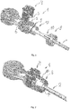
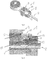
- the invention relates to a coupling end (1) of a cable (2) for controlling a gearbox of a motor vehicle to a ball joint of a part of a gear lever or a part of the gearbox.
- the tip (1) is intended to overcome the cable (2) and comprises a radial window (3) adapted to receive in engagement a plug (4) having a threaded internal portion (5).
- the plug (4) has a U-shaped profile open towards the cable (2) and is able to pass from a disengaged position, represented on the figures 2 , 4 and 5 , at an engaged position, represented on the figures 3 and 6 in which it cooperates with a threaded end portion (6) of the cable (2) and locks said cable (2) in position.
- the tip (1) comprises an annular end portion (7), coaxial with the cable (2), and receiving a safety ring (8).
- the safety ring (8) is adapted to move from an unlocking position to a locking position in which it prevents either engagement or disengagement of the plug (4).
- the ring (8) is fixed to the end piece (1) by a quarter turn assembly.
- the tip (1) also comprises an axial groove (9) adapted to cooperate with the ring (8).
- the ring (8) comprises an axially extending pin (10).
- the pin (10) when the ring (8) is in the locking position, is adapted to be interposed between the plug (4) and the window (3) to prevent engagement of the plug (4), as illustrated on the figures 2 and 4 .
- the plug (4) comprises a bore (4a) in which the pin (10) penetrates. This position corresponds to the so-called delivery position in which the cable (2) is free to move, so that the locking of the cable is done deliberately by a workshop operator.
- the pin (10) is also adapted to be positioned on the plug (4) to prevent disengagement of the plug (4), as illustrated on the figures 3 and 6 .
- This position corresponds to the operating position, once the cable installed in the vehicle.
- the fact that in the locking position of the ring (8), the pin (10) comes to be positioned on the plug (4) can provide visual information of the good engagement of the plug (4), since the ring (8) can only move in the locking position to lock the plug (4) in the engaged position, if the plug (4) is correctly engaged.
- the annular portion (7) of the nozzle (1) comprises two transverse grooves, namely a locking groove (11) and an unlocking groove (12).
- the grooves (11, 12) may be annular, i.e. disposed around the entire circumference. They can also be arranged on only part of the circumference. Other conformations are possible without departing from the scope of the invention.
- the ring (8) comprises at least one elastic lug (13) extending radially towards the cable (2).
- the ring (8) may comprise two lugs (13), diametrically opposed, in the case where the grooves (11, 12) are annular.
- the elastic lug (13) is designed to engage at rest either in the unlocking groove (12) or in the locking groove (11).
- the ring (8) is designed so that the elastic pin (13) disengages from the grooves (11, 12) when a radial force is exerted on the circumference of the ring (8).
- the ring (8) may be elastic and / or have a non-circular cross section for example oval.
- the elastic pin (13) can be mounted at the end of a tongue pivotally mounted around a hinge, so that pressure on the opposite end of the tongue causes the spacing of the lug (13) and its disengagement.
- the elastic pin (13) is close to the axis of the cable (2).
- the lateral parts of the ring (8) approach the axis of the cable (2), while the lug (10) deviates from the cable ( 2) and disengages from the groove (11, 12).
- the ring (8) may present in longitudinal section a frustoconical shape.
- the lug (13) is the part having the smallest diameter at rest. When a radial pressure is exerted on the part having the larger diameter at rest, the lug (13) deviates from the groove (11, 12).
- the ring (8) is assembled with the annular portion of the nozzle (1) by a quarter-turn rotation.
- the plug (4) is initially in the disengaged position, allowing the cable (2) to move freely.
- the ring (8) is moved axially towards the plug (4).
- a radial force is exerted on the ring (8) to move the lug (13) away from the groove (12), in order to be able to move the ring and engage in the lug (13) in the locking groove (11) .
- the pin (10) of the ring (8) is inserted between the plug (4) and the radial window (3).
- the plug (4) is locked in the disengaged position by the ring (8) in the locking position.
- the pin (10) can slide on the plug (4).
- the elastic lug (13) engages in the locking groove (11), to lock the ring (8) and to prevent disengagement of the plug (4).
- the tip (1) is secured against inadvertent disengagement and control of the gearbox is achieved in a safe manner.
- the coupling end (1) according to the invention is easy to handle, particularly in limited spaces and with visibility of the tip (1) limited.
- the end piece (1) also makes it possible to secure the stopper (4) in an engaged and disengaged position, in a simple manner and without the need to use additional parts.
Landscapes
- Engineering & Computer Science (AREA)
- General Engineering & Computer Science (AREA)
- Mechanical Engineering (AREA)
- Health & Medical Sciences (AREA)
- Oral & Maxillofacial Surgery (AREA)
- Flexible Shafts (AREA)
- Lock And Its Accessories (AREA)
- Details Of Connecting Devices For Male And Female Coupling (AREA)
- Connector Housings Or Holding Contact Members (AREA)
Priority Applications (3)
| Application Number | Priority Date | Filing Date | Title |
|---|---|---|---|
| EP17202449.9A EP3486507A1 (de) | 2017-11-17 | 2017-11-17 | Endstück zum ankoppeln eines steuerkabels eines getriebes an ein kugelgelenk |
| CN201811355344.9A CN110034426A (zh) | 2017-11-17 | 2018-11-14 | 用于将变速器控制电缆连接到球形接头的尾端件 |
| US16/191,532 US11193525B2 (en) | 2017-11-17 | 2018-11-15 | Coupling end piece for a control cable from a gearbox to a ball joint |
Applications Claiming Priority (1)
| Application Number | Priority Date | Filing Date | Title |
|---|---|---|---|
| EP17202449.9A EP3486507A1 (de) | 2017-11-17 | 2017-11-17 | Endstück zum ankoppeln eines steuerkabels eines getriebes an ein kugelgelenk |
Publications (1)
| Publication Number | Publication Date |
|---|---|
| EP3486507A1 true EP3486507A1 (de) | 2019-05-22 |
Family
ID=60409197
Family Applications (1)
| Application Number | Title | Priority Date | Filing Date |
|---|---|---|---|
| EP17202449.9A Withdrawn EP3486507A1 (de) | 2017-11-17 | 2017-11-17 | Endstück zum ankoppeln eines steuerkabels eines getriebes an ein kugelgelenk |
Country Status (3)
| Country | Link |
|---|---|
| US (1) | US11193525B2 (de) |
| EP (1) | EP3486507A1 (de) |
| CN (1) | CN110034426A (de) |
Families Citing this family (1)
| Publication number | Priority date | Publication date | Assignee | Title |
|---|---|---|---|---|
| JP6931594B2 (ja) * | 2017-11-16 | 2021-09-08 | 中央発條株式会社 | 端末固定装置 |
Citations (6)
| Publication number | Priority date | Publication date | Assignee | Title |
|---|---|---|---|---|
| WO1994010467A1 (es) * | 1992-10-26 | 1994-05-11 | Fico Cables, S.A. | Dispositivo autoajustador de la longitud de cables de mando |
| EP0899469A1 (de) * | 1996-05-14 | 1999-03-03 | Fico Cables, S.A. | Einstellvorrichtung für kabelzugendstücke |
| US20060230868A1 (en) * | 2005-04-18 | 2006-10-19 | Ruhlander Gregory P | Compact core adjuster with vibration dampening |
| ES2264606A1 (es) * | 2004-07-05 | 2007-01-01 | Melchor Daumal Castellon | Dispositivo para la regulacion de la longitud de una funda y/o un cable de mando. |
| EP2495460A2 (de) * | 2011-03-04 | 2012-09-05 | SCS Deutschland GmbH & Co. KG | Bowdenzugkupplung |
| US20160258474A1 (en) * | 2014-07-03 | 2016-09-08 | Infac Corporation | Cable Connection Apparatus for Vehicles |
Family Cites Families (7)
| Publication number | Priority date | Publication date | Assignee | Title |
|---|---|---|---|---|
| US5682797A (en) * | 1996-07-08 | 1997-11-04 | Teleflex Incorporated | Adjustment lock with lock fingers |
| CN201166096Y (zh) * | 2007-10-17 | 2008-12-17 | 石铭正 | 圆体变速箱及换挡装置 |
| US8850920B2 (en) * | 2008-10-10 | 2014-10-07 | Kongsberg Driveline Systems I, Inc. | Adjustment device for a remote control assembly having an easily engageable and disengageable locking element |
| JP5294402B2 (ja) * | 2008-10-23 | 2013-09-18 | 矢崎総業株式会社 | 電気接続箱 |
| US8519267B2 (en) * | 2009-02-16 | 2013-08-27 | Carlisle Interconnect Technologies, Inc. | Terminal having integral oxide breaker |
| JP2014017085A (ja) * | 2012-07-06 | 2014-01-30 | Sumitomo Wiring Syst Ltd | コネクタ |
| DE202014106116U1 (de) * | 2014-12-17 | 2016-03-18 | Dura Automotive Body & Glass Systems Gmbh | Rahmenstruktur einer Kraftfahrzeugtür |
-
2017
- 2017-11-17 EP EP17202449.9A patent/EP3486507A1/de not_active Withdrawn
-
2018
- 2018-11-14 CN CN201811355344.9A patent/CN110034426A/zh active Pending
- 2018-11-15 US US16/191,532 patent/US11193525B2/en active Active
Patent Citations (7)
| Publication number | Priority date | Publication date | Assignee | Title |
|---|---|---|---|---|
| WO1994010467A1 (es) * | 1992-10-26 | 1994-05-11 | Fico Cables, S.A. | Dispositivo autoajustador de la longitud de cables de mando |
| EP0899469A1 (de) * | 1996-05-14 | 1999-03-03 | Fico Cables, S.A. | Einstellvorrichtung für kabelzugendstücke |
| ES2264606A1 (es) * | 2004-07-05 | 2007-01-01 | Melchor Daumal Castellon | Dispositivo para la regulacion de la longitud de una funda y/o un cable de mando. |
| US20060230868A1 (en) * | 2005-04-18 | 2006-10-19 | Ruhlander Gregory P | Compact core adjuster with vibration dampening |
| US7779720B2 (en) | 2005-04-18 | 2010-08-24 | Dura Global Technologies, Llc | Compact core adjuster with vibration dampening |
| EP2495460A2 (de) * | 2011-03-04 | 2012-09-05 | SCS Deutschland GmbH & Co. KG | Bowdenzugkupplung |
| US20160258474A1 (en) * | 2014-07-03 | 2016-09-08 | Infac Corporation | Cable Connection Apparatus for Vehicles |
Also Published As
| Publication number | Publication date |
|---|---|
| CN110034426A (zh) | 2019-07-19 |
| US11193525B2 (en) | 2021-12-07 |
| US20190154077A1 (en) | 2019-05-23 |
Similar Documents
| Publication | Publication Date | Title |
|---|---|---|
| EP0806531B1 (de) | Axial (ent)kuppelndes Schloss für ein Schlossmechanismus eines Personenkraftwagens | |
| EP2024219B1 (de) | System zur arretierung eines schafts in einer bestimmten lage im verhältnis zu einem anderen schaft unter eliminierung des spielraums zwischen den beiden schäften | |
| EP2048425B1 (de) | Anschlussbuchse und eine solche Buchse umfassender Anschluss | |
| WO2003008852A1 (fr) | Connecteur rapide | |
| EP0743053A1 (de) | Sicherheits- und Kontrollvorrichtung der Verriegelung einer Radnabe, insbesondere für Rollstuhl | |
| FR2836202A1 (fr) | Raccord destine a relier des conduites hydrauliques | |
| FR2922614A1 (fr) | Dispositif de pre-reglage et de fixation autobloquant d'un cable | |
| EP3486507A1 (de) | Endstück zum ankoppeln eines steuerkabels eines getriebes an ein kugelgelenk | |
| FR2776325A1 (fr) | Verrou a debrayage axial perfectionne pour un mecanisme de serrure de vehicule automobile | |
| FR2500896A1 (fr) | Dispositif de fixation sur une paroi de l'extremite d'une gaine dans laquelle est recu coulissant un cable de commande | |
| FR2788478A1 (fr) | Antivol de direction de vehicule automobile | |
| EP3209908A1 (de) | Vorrichtung zur kontrolle der position eines getriebeschalthebels | |
| FR2718497A3 (fr) | Dispositif d'assemblage de panneaux par vissage. | |
| EP1020677B1 (de) | Verbinderanordnung | |
| EP3105473A1 (de) | Vorrichtung zum betrieb eines betätigungskabels und verwendung bei einer rückwärtsgangsperrsteuerung eines kraftfahrzeuggetriebes | |
| EP2092404B1 (de) | Abnehmbare vorrichtung zur befestigung eines knaufs auf der stange eines getriebes in einem automobil | |
| EP1757829B1 (de) | Vorrichtung zur Erzeugung eines vordefinierten Spannungszustands bei Bedienungsvorrichtung mit einem in eine Führungshülle eingelegten Kabel | |
| EP3885592A1 (de) | Blindmontageanordnung eines bremsseils an einem betätigungshebel einer kraftfahrzeug-trommelbremse | |
| EP2483129B1 (de) | System zum anbringen eines moduls für das oberteil einer lenksäule | |
| FR2920104A1 (fr) | Mandrin porte-outil pour l'equipement d'une machine tournante | |
| EP0731005B1 (de) | Lenkradschloss für ein Kraftfahrzeug | |
| EP1036960B1 (de) | Vorrichtung in einem Schaltgetriebe für Kraftfahrzeuge zum Einbau und Zerlegen eines Kabels, welches einen Schalthebel mit einer Sicherheitssperre verbindet | |
| EP0731243B1 (de) | Riegel mit entkuppelbarem Rotor und Automobillenkschloss mit einem solchen Riegel | |
| FR2910086A1 (fr) | Embout de gaine pour selection et commande a cables d'une boite de vitesses de vehicule automobile | |
| WO2021170941A1 (fr) | Moyen de demarrage comportant un capot de cle et vehicule equipe d'un tel moyen |
Legal Events
| Date | Code | Title | Description |
|---|---|---|---|
| PUAI | Public reference made under article 153(3) epc to a published international application that has entered the european phase |
Free format text: ORIGINAL CODE: 0009012 |
|
| AK | Designated contracting states |
Kind code of ref document: A1 Designated state(s): AL AT BE BG CH CY CZ DE DK EE ES FI FR GB GR HR HU IE IS IT LI LT LU LV MC MK MT NL NO PL PT RO RS SE SI SK SM TR |
|
| AX | Request for extension of the european patent |
Extension state: BA ME |
|
| STAA | Information on the status of an ep patent application or granted ep patent |
Free format text: STATUS: THE APPLICATION IS DEEMED TO BE WITHDRAWN |
|
| 18D | Application deemed to be withdrawn |
Effective date: 20191123 |