EP3486507A1 - Mating tip of a cable for controlling a gearbox with a ball joint - Google Patents
Mating tip of a cable for controlling a gearbox with a ball joint Download PDFInfo
- Publication number
- EP3486507A1 EP3486507A1 EP17202449.9A EP17202449A EP3486507A1 EP 3486507 A1 EP3486507 A1 EP 3486507A1 EP 17202449 A EP17202449 A EP 17202449A EP 3486507 A1 EP3486507 A1 EP 3486507A1
- Authority
- EP
- European Patent Office
- Prior art keywords
- ring
- cable
- plug
- locking
- coupling end
- Prior art date
- Legal status (The legal status is an assumption and is not a legal conclusion. Google has not performed a legal analysis and makes no representation as to the accuracy of the status listed.)
- Withdrawn
Links
Images

Classifications
-
- F—MECHANICAL ENGINEERING; LIGHTING; HEATING; WEAPONS; BLASTING
- F16—ENGINEERING ELEMENTS AND UNITS; GENERAL MEASURES FOR PRODUCING AND MAINTAINING EFFECTIVE FUNCTIONING OF MACHINES OR INSTALLATIONS; THERMAL INSULATION IN GENERAL
- F16C—SHAFTS; FLEXIBLE SHAFTS; ELEMENTS OR CRANKSHAFT MECHANISMS; ROTARY BODIES OTHER THAN GEARING ELEMENTS; BEARINGS
- F16C1/00—Flexible shafts; Mechanical means for transmitting movement in a flexible sheathing
- F16C1/10—Means for transmitting linear movement in a flexible sheathing, e.g. "Bowden-mechanisms"
- F16C1/22—Adjusting; Compensating length
- F16C1/223—Adjusting; Compensating length by adjusting the effective length of the flexible member
-
- F—MECHANICAL ENGINEERING; LIGHTING; HEATING; WEAPONS; BLASTING
- F16—ENGINEERING ELEMENTS AND UNITS; GENERAL MEASURES FOR PRODUCING AND MAINTAINING EFFECTIVE FUNCTIONING OF MACHINES OR INSTALLATIONS; THERMAL INSULATION IN GENERAL
- F16C—SHAFTS; FLEXIBLE SHAFTS; ELEMENTS OR CRANKSHAFT MECHANISMS; ROTARY BODIES OTHER THAN GEARING ELEMENTS; BEARINGS
- F16C1/00—Flexible shafts; Mechanical means for transmitting movement in a flexible sheathing
- F16C1/10—Means for transmitting linear movement in a flexible sheathing, e.g. "Bowden-mechanisms"
- F16C1/12—Arrangements for transmitting movement to or from the flexible member
- F16C1/14—Construction of the end-piece of the flexible member; Attachment thereof to the flexible member
- F16C1/145—Attachment of the end-piece to the flexible member
-
- F—MECHANICAL ENGINEERING; LIGHTING; HEATING; WEAPONS; BLASTING
- F16—ENGINEERING ELEMENTS AND UNITS; GENERAL MEASURES FOR PRODUCING AND MAINTAINING EFFECTIVE FUNCTIONING OF MACHINES OR INSTALLATIONS; THERMAL INSULATION IN GENERAL
- F16H—GEARING
- F16H61/00—Control functions within control units of change-speed- or reversing-gearings for conveying rotary motion ; Control of exclusively fluid gearing, friction gearing, gearings with endless flexible members or other particular types of gearing
- F16H61/26—Generation or transmission of movements for final actuating mechanisms
- F16H61/36—Generation or transmission of movements for final actuating mechanisms with at least one movement being transmitted by a cable
-
- H—ELECTRICITY
- H01—ELECTRIC ELEMENTS
- H01R—ELECTRICALLY-CONDUCTIVE CONNECTIONS; STRUCTURAL ASSOCIATIONS OF A PLURALITY OF MUTUALLY-INSULATED ELECTRICAL CONNECTING ELEMENTS; COUPLING DEVICES; CURRENT COLLECTORS
- H01R11/00—Individual connecting elements providing two or more spaced connecting locations for conductive members which are, or may be, thereby interconnected, e.g. end pieces for wires or cables supported by the wire or cable and having means for facilitating electrical connection to some other wire, terminal, or conductive member, blocks of binding posts
- H01R11/11—End pieces or tapping pieces for wires, supported by the wire and for facilitating electrical connection to some other wire, terminal or conductive member
- H01R11/12—End pieces terminating in an eye, hook, or fork
-
- F—MECHANICAL ENGINEERING; LIGHTING; HEATING; WEAPONS; BLASTING
- F16—ENGINEERING ELEMENTS AND UNITS; GENERAL MEASURES FOR PRODUCING AND MAINTAINING EFFECTIVE FUNCTIONING OF MACHINES OR INSTALLATIONS; THERMAL INSULATION IN GENERAL
- F16C—SHAFTS; FLEXIBLE SHAFTS; ELEMENTS OR CRANKSHAFT MECHANISMS; ROTARY BODIES OTHER THAN GEARING ELEMENTS; BEARINGS
- F16C2361/00—Apparatus or articles in engineering in general
- F16C2361/65—Gear shifting, change speed gear, gear box
-
- F—MECHANICAL ENGINEERING; LIGHTING; HEATING; WEAPONS; BLASTING
- F16—ENGINEERING ELEMENTS AND UNITS; GENERAL MEASURES FOR PRODUCING AND MAINTAINING EFFECTIVE FUNCTIONING OF MACHINES OR INSTALLATIONS; THERMAL INSULATION IN GENERAL
- F16H—GEARING
- F16H2704/00—Control mechanisms and elements applying a mechanical movement
-
- H—ELECTRICITY
- H01—ELECTRIC ELEMENTS
- H01R—ELECTRICALLY-CONDUCTIVE CONNECTIONS; STRUCTURAL ASSOCIATIONS OF A PLURALITY OF MUTUALLY-INSULATED ELECTRICAL CONNECTING ELEMENTS; COUPLING DEVICES; CURRENT COLLECTORS
- H01R2201/00—Connectors or connections adapted for particular applications
- H01R2201/26—Connectors or connections adapted for particular applications for vehicles
Definitions
- the invention relates to the technical sector of equipment for motor vehicles.
- the invention relates to the coupling of the control cables of a gearbox to a ball joint that presents part of a gear lever on the one hand, or that presents a part of the gearbox of somewhere else.
- the control cables are particularly assigned to the selection and / or shifting.
- the gearbox can be a manual gearbox or an automatic gearbox.
- the coupling end is intended to overcome the end of the cable.
- the cable is inserted inside the nozzle at a certain length of engagement, and is immobilized relative to the nozzle during use of the vehicle.
- a prior adjustment of the engagement length is necessary to adapt to different vehicle configurations. Then, during the life of the coupling end, and because of the wear and increase of play between its components, the setting of the cable engagement length can be repeated to ensure accurate control selection and / or shifting.
- a coupling end comprising a device for locking and unlocking the cable, for the purpose of adjusting its length of engagement in the tip.
- a coupling end is for example disclosed by the document US7,779,720 .
- the tip described in this document comprises a radial window adapted to receive in engagement a plug having a threaded internal portion.
- the cap is adapted to move from a disengaged position to an engaged position in which it cooperates with a threaded end portion of the cable, and locks said cable in position.
- the cap Before installation of the coupling end piece in the vehicle, and for example during delivery or handling of said cable equipped with the endpiece, the cap is held in the disengaged position by a security element in the form of a slider provided with a lug adapted to be moved axially to lock the cap in a disengaged position.
- a security element in the form of a slider provided with a lug adapted to be moved axially to lock the cap in a disengaged position.
- the cap comprises, for its part, resilient tongues equipped with lugs cooperating with grooves provided on the endpiece for holding the cap in the engaged position.
- This type of coupling end generally has the disadvantage that its handling is difficult. Indeed, during the installation of the tip, and when it is necessary to adjust the length of engagement of the cable relative to the tip, the limited space present around the gearbox makes difficult access and handling the engagement cap and the safety slider. Especially since to disengage the cap, the use of a screwdriver type tool seems necessary to unlock the lugs of the slider and tabs.
- One of the aims of the invention is therefore to propose a coupling end of a control cable of a gearbox, adjustable, which can be locked or unlocked on the cable by pressing a plug, and allowing to provide a so-called delivery function in which the locking of the cable is prevented, and a so-called operational function in which the disengagement of the plug is prevented.
- Another object of the invention is also to provide visual information of the good locking of the cable.
- Another object is to provide such a coupling end which means to prevent engagement or disengagement of the cap are easy to handle, particularly in areas that are not very visible and difficult to access.
- Another object of the invention is to secure the cap in a position engaged and disengaged, simply and reliably, without the need to use additional part or tool.
- the endpiece is intended to overcome the cable and comprises a radial window adapted to receive a cap engagement having a threaded internal portion, the plug being adapted to move from a disengaged position to an engaged position in which it cooperates with a portion of threaded end of the cable and locks said cable in position.
- the tip comprises an annular end portion, coaxial with the cable, and receiving a safety ring.
- the security ring is adapted to move from an unlocking position to a locking position in which it prevents either engagement or disengagement of the cap.
- the ring ensures a so-called delivery function in which the locking of the cable is prevented, and a so-called operational function in which the disengagement of the plug is prevented.
- Handling of the ring is easy and possible without visibility and in hard to reach areas. In the workshop simply adjust the length of cable engagement in the coupling end, pass the ring in the unlocked position to allow to engage the cap, and pass the ring in the locking position to prevent disengagement of the plug.
- the operation is simple and reliable.
- the ring can be locked in a position in which it prevents the engagement or disengagement of the cap, or in a neutral position in which it allows the displacement of the cap in the engaged or disengaged position.
- the disengagement of the elastic lug is effected by transverse pressure on the ring.
- the plug can be either free to move between the engaged position and the disengaged position, or be blocked in one of these positions.
- the cap can assume a position called delivery (disengaged) or operating (engaged) and be blocked safely and simply.
- delivery (disengaged) or operating (engaged) a position called delivery (disengaged) or operating (engaged) and be blocked safely and simply.
- the fact that in locking position of the ring, the pin comes to be positioned on the cap provides a visual information of the good engagement of the cap. Indeed, the ring can move in the locking position to lock the cap in the engaged position, if the cap is properly engaged.
- the ring and the coaxial annular portion comprise complementary retaining means, for example in the form of a quarter turn assembly.
- complementary retaining means for example in the form of a quarter turn assembly.
- the invention relates to a coupling end (1) of a cable (2) for controlling a gearbox of a motor vehicle to a ball joint of a part of a gear lever or a part of the gearbox.
- the tip (1) is intended to overcome the cable (2) and comprises a radial window (3) adapted to receive in engagement a plug (4) having a threaded internal portion (5).
- the plug (4) has a U-shaped profile open towards the cable (2) and is able to pass from a disengaged position, represented on the figures 2 , 4 and 5 , at an engaged position, represented on the figures 3 and 6 in which it cooperates with a threaded end portion (6) of the cable (2) and locks said cable (2) in position.
- the tip (1) comprises an annular end portion (7), coaxial with the cable (2), and receiving a safety ring (8).
- the safety ring (8) is adapted to move from an unlocking position to a locking position in which it prevents either engagement or disengagement of the plug (4).
- the ring (8) is fixed to the end piece (1) by a quarter turn assembly.
- the tip (1) also comprises an axial groove (9) adapted to cooperate with the ring (8).
- the ring (8) comprises an axially extending pin (10).
- the pin (10) when the ring (8) is in the locking position, is adapted to be interposed between the plug (4) and the window (3) to prevent engagement of the plug (4), as illustrated on the figures 2 and 4 .
- the plug (4) comprises a bore (4a) in which the pin (10) penetrates. This position corresponds to the so-called delivery position in which the cable (2) is free to move, so that the locking of the cable is done deliberately by a workshop operator.
- the pin (10) is also adapted to be positioned on the plug (4) to prevent disengagement of the plug (4), as illustrated on the figures 3 and 6 .
- This position corresponds to the operating position, once the cable installed in the vehicle.
- the fact that in the locking position of the ring (8), the pin (10) comes to be positioned on the plug (4) can provide visual information of the good engagement of the plug (4), since the ring (8) can only move in the locking position to lock the plug (4) in the engaged position, if the plug (4) is correctly engaged.
- the annular portion (7) of the nozzle (1) comprises two transverse grooves, namely a locking groove (11) and an unlocking groove (12).
- the grooves (11, 12) may be annular, i.e. disposed around the entire circumference. They can also be arranged on only part of the circumference. Other conformations are possible without departing from the scope of the invention.
- the ring (8) comprises at least one elastic lug (13) extending radially towards the cable (2).
- the ring (8) may comprise two lugs (13), diametrically opposed, in the case where the grooves (11, 12) are annular.
- the elastic lug (13) is designed to engage at rest either in the unlocking groove (12) or in the locking groove (11).
- the ring (8) is designed so that the elastic pin (13) disengages from the grooves (11, 12) when a radial force is exerted on the circumference of the ring (8).
- the ring (8) may be elastic and / or have a non-circular cross section for example oval.
- the elastic pin (13) can be mounted at the end of a tongue pivotally mounted around a hinge, so that pressure on the opposite end of the tongue causes the spacing of the lug (13) and its disengagement.
- the elastic pin (13) is close to the axis of the cable (2).
- the lateral parts of the ring (8) approach the axis of the cable (2), while the lug (10) deviates from the cable ( 2) and disengages from the groove (11, 12).
- the ring (8) may present in longitudinal section a frustoconical shape.
- the lug (13) is the part having the smallest diameter at rest. When a radial pressure is exerted on the part having the larger diameter at rest, the lug (13) deviates from the groove (11, 12).
- the ring (8) is assembled with the annular portion of the nozzle (1) by a quarter-turn rotation.
- the plug (4) is initially in the disengaged position, allowing the cable (2) to move freely.
- the ring (8) is moved axially towards the plug (4).
- a radial force is exerted on the ring (8) to move the lug (13) away from the groove (12), in order to be able to move the ring and engage in the lug (13) in the locking groove (11) .
- the pin (10) of the ring (8) is inserted between the plug (4) and the radial window (3).
- the plug (4) is locked in the disengaged position by the ring (8) in the locking position.
- the pin (10) can slide on the plug (4).
- the elastic lug (13) engages in the locking groove (11), to lock the ring (8) and to prevent disengagement of the plug (4).
- the tip (1) is secured against inadvertent disengagement and control of the gearbox is achieved in a safe manner.
- the coupling end (1) according to the invention is easy to handle, particularly in limited spaces and with visibility of the tip (1) limited.
- the end piece (1) also makes it possible to secure the stopper (4) in an engaged and disengaged position, in a simple manner and without the need to use additional parts.
Abstract
L'invention concerne un embout d'accouplement (1) d'un câble (2) de commande d'une boîte de vitesses d'un véhicule automobile à une rotule d'une partie d'un levier de vitesses ou d'une partie de la boîte de vitesses, l'embout (1) étant destiné à surmonter le câble (2) et comprend une fenêtre radiale (3) apte à recevoir en engagement un bouchon (4) présentant une portion interne filetée, le bouchon (4) étant apte à passer d'une position désengagée à une position engagée dans laquelle il coopère avec une portion d'extrémité filetée du câble (2) et verrouille ledit câble (2) en position. Selon l'invention l'embout (1) comprend une portion annulaire d'extrémité (9), coaxiale au câble (2), et recevant une bague de sécurité (8), ladite bague de sécurité (8) étant apte à passer d'une position de déverrouillage à une position de verrouillage dans laquelle elle empêche soit l'engagement soit le désengagement du bouchon (4).The invention relates to a coupling end (1) of a cable (2) for controlling a gearbox of a motor vehicle to a ball joint of a part of a gear lever or a part of the gearbox, the tip (1) being intended to overcome the cable (2) and comprises a radial window (3) adapted to receive in engagement a plug (4) having a threaded internal portion, the plug (4) being able to move from a disengaged position to an engaged position in which it cooperates with a threaded end portion of the cable (2) and locks said cable (2) in position. According to the invention the tip (1) comprises an annular end portion (9), coaxial with the cable (2), and receiving a safety ring (8), said safety ring (8) being able to pass from an unlocking position at a locking position in which it prevents either engagement or disengagement of the plug (4).
Description
L'invention se rattache au secteur technique des équipements pour véhicules automobiles.The invention relates to the technical sector of equipment for motor vehicles.
Plus particulièrement, l'invention concerne l'accouplement des câbles de commande d'une boîte de vitesses à une rotule que présente une partie d'un levier de vitesses d'une part, ou que présente une partie de la boîte de vitesses d'autre part. Les câbles de commande sont notamment affectés à la sélection et/ou au passage des vitesses.More particularly, the invention relates to the coupling of the control cables of a gearbox to a ball joint that presents part of a gear lever on the one hand, or that presents a part of the gearbox of somewhere else. The control cables are particularly assigned to the selection and / or shifting.
Il est connu de l'état de la technique un embout d'accouplement comprenant un logement recevant une pièce d'accouplement destinée à venir coiffer et s'accoupler avec ladite rotule. La boîte de vitesse peut être une boîte manuelle ou une boîte automatique.It is known from the state of the art a coupling end comprising a housing receiving a coupling part intended to cap and mate with said ball joint. The gearbox can be a manual gearbox or an automatic gearbox.
De façon connue, l'embout d'accouplement est destiné à surmonter l'extrémité du câble. Ainsi, le câble est inséré à l'intérieur de l'embout selon une certaine longueur d'engagement, et est immobilisé par rapport à l'embout pendant l'utilisation du véhicule. En pratique, un réglage préalable de la longueur d'engagement est nécessaire pour s'adapter aux différentes configurations des véhicules. Ensuite, au cours de la vie de l'embout d'accouplement, et du fait de l'usure et l'augmentation des jeux entre ses composants, le réglage de la longueur d'engagement du câble peut être répété pour assurer un contrôle précis de la sélection et/ou du passage des vitesses.In known manner, the coupling end is intended to overcome the end of the cable. Thus, the cable is inserted inside the nozzle at a certain length of engagement, and is immobilized relative to the nozzle during use of the vehicle. In practice, a prior adjustment of the engagement length is necessary to adapt to different vehicle configurations. Then, during the life of the coupling end, and because of the wear and increase of play between its components, the setting of the cable engagement length can be repeated to ensure accurate control selection and / or shifting.
A cet effet, il est connu de l'état de la technique un embout d'accouplement comprenant un dispositif de verrouillage et de déverrouillage du câble, à des fins de réglage de sa longueur d'engagement dans l'embout. Un tel embout d'accouplement est par exemple divulgué par le document
Ainsi, avant installation de l'embout d'accouplement dans le véhicule, et par exemple pendant la livraison ou la manutention dudit câble équipé de l'embout, le bouchon est maintenu en position désengagée par un élément de sécurité sous forme d'un curseur pourvu d'un ergot apte à être déplacé axialement pour verrouiller le bouchon dans une position désengagée. De cette manière, le verrouillage du câble est effectué en atelier par un opérateur selon la longueur d'engagement souhaitée. Le bouchon comprend, quant à lui, des languettes élastiques équipées d'ergots coopérant avec des rainures ménagées sur l'embout pour le maintien du bouchon en position engagée.Thus, before installation of the coupling end piece in the vehicle, and for example during delivery or handling of said cable equipped with the endpiece, the cap is held in the disengaged position by a security element in the form of a slider provided with a lug adapted to be moved axially to lock the cap in a disengaged position. In this way, the locking of the cable is performed in the workshop by an operator according to the desired engagement length. The cap comprises, for its part, resilient tongues equipped with lugs cooperating with grooves provided on the endpiece for holding the cap in the engaged position.
Ce type d'embout d'accouplement présente généralement l'inconvénient que sa manipulation est difficile. En effet, lors de l'installation de l'embout, et lorsqu'il convient de régler la longueur d'engagement du câble par rapport à l'embout, l'espace limité présent autour de la boîte de vitesses rend difficile l'accès et la manipulation du bouchon d'engagement et du curseur de sécurité. D'autant plus que pour désengager le bouchon, l'utilisation d'un outil type tournevis semble nécessaire pour déverrouiller les ergots du curseur et des languettes.This type of coupling end generally has the disadvantage that its handling is difficult. Indeed, during the installation of the tip, and when it is necessary to adjust the length of engagement of the cable relative to the tip, the limited space present around the gearbox makes difficult access and handling the engagement cap and the safety slider. Especially since to disengage the cap, the use of a screwdriver type tool seems necessary to unlock the lugs of the slider and tabs.
L'un des buts de l'invention est donc de proposer un embout d'accouplement d'un câble de commande d'une boîte de vitesses, ajustable, pouvant être verrouillé ou déverrouillé sur le câble par pression d'un bouchon, et permettant d'assurer une fonction dite de livraison dans laquelle le verrouillage du câble est empêché, et une fonction dite opérationnelle dans laquelle le désengagement du bouchon est empêché.One of the aims of the invention is therefore to propose a coupling end of a control cable of a gearbox, adjustable, which can be locked or unlocked on the cable by pressing a plug, and allowing to provide a so-called delivery function in which the locking of the cable is prevented, and a so-called operational function in which the disengagement of the plug is prevented.
Un autre objectif de l'invention est également de fournir une information visuelle du bon verrouillage du câble.Another object of the invention is also to provide visual information of the good locking of the cable.
Un autre objectif est de fournir un tel embout d'accouplement dont les moyens permettant d'empêcher l'engagement ou le désengagement du bouchon sont faciles à manipuler, particulièrement dans des espaces peu visibles et difficiles d'accès.Another object is to provide such a coupling end which means to prevent engagement or disengagement of the cap are easy to handle, particularly in areas that are not very visible and difficult to access.
Un autre objectif de l'invention est de sécuriser le bouchon dans une position engagée et désengagée, de façon simple et fiable, sans nécessité d'utiliser de pièce complémentaire ni d'outil.Another object of the invention is to secure the cap in a position engaged and disengaged, simply and reliably, without the need to use additional part or tool.
Afin de résoudre les problèmes précités, il a été mis au point un embout d'accouplement d'un câble de commande d'une boîte de vitesses d'un véhicule automobile à une rotule d'une partie d'un levier de vitesses ou d'une partie de la boîte de vitesses. L'embout est destiné à surmonter le câble et comprend une fenêtre radiale apte à recevoir en engagement un bouchon présentant une portion interne filetée, le bouchon étant apte à passer d'une position désengagée à une position engagée dans laquelle il coopère avec une portion d'extrémité filetée du câble et verrouille ledit câble en position.In order to solve the aforementioned problems, it has been developed a coupling end of a control cable of a gearbox of a motor vehicle to a ball joint of a part of a shifter or a gearbox. part of the gearbox. The endpiece is intended to overcome the cable and comprises a radial window adapted to receive a cap engagement having a threaded internal portion, the plug being adapted to move from a disengaged position to an engaged position in which it cooperates with a portion of threaded end of the cable and locks said cable in position.
Selon l'invention, l'embout comprend une portion annulaire d'extrémité, coaxiale au câble, et recevant une bague de sécurité. La bague de sécurité est apte à passer d'une position de déverrouillage à une position de verrouillage dans laquelle elle empêche soit l'engagement soit le désengagement du bouchon.According to the invention, the tip comprises an annular end portion, coaxial with the cable, and receiving a safety ring. The security ring is adapted to move from an unlocking position to a locking position in which it prevents either engagement or disengagement of the cap.
De cette manière, la bague permet d'assurer une fonction dite de livraison dans laquelle le verrouillage du câble est empêché, et une fonction dite opérationnelle dans laquelle le désengagement du bouchon est empêché. La manipulation de la bague est facile et possible sans visibilité et dans des espaces difficiles d'accès. En atelier il suffit simplement d'ajuster la longueur d'engagement du câble dans l'embout d'accouplement, de passer la bague dans la position de déverrouillage pour permettre d'engager le bouchon, et de passer la bague dans la position de verrouillage pour empêcher le désengagement du bouchon.In this way, the ring ensures a so-called delivery function in which the locking of the cable is prevented, and a so-called operational function in which the disengagement of the plug is prevented. Handling of the ring is easy and possible without visibility and in hard to reach areas. In the workshop simply adjust the length of cable engagement in the coupling end, pass the ring in the unlocked position to allow to engage the cap, and pass the ring in the locking position to prevent disengagement of the plug.
De préférence, la portion annulaire comprend une rainure de verrouillage et une rainure de déverrouillage, et la bague comprend au moins un ergot élastique apte, dans un mouvement de coulissement de la bague, à venir s'engager :
- dans la rainure de verrouillage pour verrouiller la bague dans la position de verrouillage ou;
- dans la rainure de déverrouillage pour verrouiller la bague dans la position de déverrouillage.
- in the locking groove for locking the ring in the locking position or;
- in the unlocking groove to lock the ring in the unlock position.
Ainsi, le fonctionnement est simple et fiable. La bague peut être verrouillée dans une position dans laquelle elle empêche l'engagement ou le désengagement du bouchon, ou dans une position neutre dans laquelle elle permet le déplacement du bouchon dans la position engagée ou désengagée.Thus, the operation is simple and reliable. The ring can be locked in a position in which it prevents the engagement or disengagement of the cap, or in a neutral position in which it allows the displacement of the cap in the engaged or disengaged position.
Avantageusement, le désengagement de l'ergot élastique s'effectue par pression transversale sur la bague.Advantageously, the disengagement of the elastic lug is effected by transverse pressure on the ring.
Selon une forme de réalisation particulière, la bague comprend une broche s'étendant axialement et destinée, lorsque la bague est dans la position de verrouillage, à venir soit :
- s'intercaler entre le bouchon et la fenêtre pour empêcher l'engagement du bouchon ;
- se positionner sur le bouchon pour empêcher le désengagement du bouchon.
- to be inserted between the stopper and the window to prevent the engagement of the stopper;
- position yourself on the cap to prevent disengagement of the cap.
De cette manière le bouchon peut être soit être libre à se déplacer entre la position engagée et la position désengagée, soit être bloqué dans une de ces positions. Ainsi le bouchon peut assumer une position dite de livraison (désengagée) ou d'exploitation (engagée) et y être bloqué de façon sûre et simple. Le fait qu'en position de verrouillage de la bague, la broche vienne se positionner sur le bouchon permet de fournir une information visuelle du bon engagement du bouchon. En effet, la bague ne peut se déplacer en position de verrouillage pour bloquer le bouchon dans la position engagée, que si le bouchon est correctement engagé.In this way the plug can be either free to move between the engaged position and the disengaged position, or be blocked in one of these positions. Thus the cap can assume a position called delivery (disengaged) or operating (engaged) and be blocked safely and simply. The fact that in locking position of the ring, the pin comes to be positioned on the cap provides a visual information of the good engagement of the cap. Indeed, the ring can move in the locking position to lock the cap in the engaged position, if the cap is properly engaged.
De préférence, la bague et la portion annulaire coaxiale comprennent des moyens de retenus complémentaires, par exemple sous la forme d'un assemblage quart de tour. De cette manière, la bague est maintenue sur l'embout et ne risque pas de se perdre. La manipulation de la bague est simple.Preferably, the ring and the coaxial annular portion comprise complementary retaining means, for example in the form of a quarter turn assembly. In this way, the ring is held on the tip and is not likely to get lost. The handling of the ring is simple.
D'autres caractéristiques et avantages de l'invention ressortiront clairement de la description qui en est réalisée ci-après, à titre indicatif et nullement limitatif, en référence aux figures annexées, dans lesquelles :
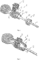
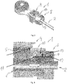
- la
figure 1 est une représentation en vue éclatée de l'embout d'accouplement selon l'invention ; - la
figure 2 est une représentation schématique en perspective de l'embout selon l'invention avec le bouchon en position désengagée et la bague en position de verrouillage ; - la
figure 3 est une représentation schématique en perspective de l'embout selon l'invention avec le bouchon en position engagée et la bague en position de verrouillage ; - la
figure 4 est une vue en coupe longitudinale correspondant à lafigure 2 , avec le bouchon en position désengagée et la bague en position de verrouillage ; - la
figure 5 est une vue en coupe longitudinale de l'embout selon l'invention avec le bouchon en position désengagée et la bague en position de déverrouillage ; - la
figure 6 est une vue en coupe longitudinale correspondant à lafigure 3 , avec le bouchon en position engagée et la bague en position de verrouillage.
- the
figure 1 is an exploded view of the coupling end according to the invention; - the
figure 2 is a schematic representation in perspective of the nozzle according to the invention with the cap in the disengaged position and the ring in the locking position; - the
figure 3 is a schematic representation in perspective of the nozzle according to the invention with the cap in the engaged position and the ring in the locking position; - the
figure 4 is a longitudinal sectional view corresponding to thefigure 2 with the cap in the disengaged position and the ring in the locked position; - the
figure 5 is a longitudinal sectional view of the nozzle according to the invention with the cap in the disengaged position and the ring in the unlocked position; - the
figure 6 is a longitudinal sectional view corresponding to thefigure 3 , with the cap in the engaged position and the ring in the locking position.
L'invention concerne un embout d'accouplement (1) d'un câble (2) de commande d'une boîte de vitesses d'un véhicule automobile à une rotule d'une partie d'un levier de vitesses ou d'une partie de la boîte de vitesses.The invention relates to a coupling end (1) of a cable (2) for controlling a gearbox of a motor vehicle to a ball joint of a part of a gear lever or a part of the gearbox.
L'embout (1) est destiné à surmonter le câble (2) et comprend une fenêtre radiale (3) apte à recevoir en engagement un bouchon (4) présentant une portion interne filetée (5). Le bouchon (4) présente un profil en U ouvert vers le câble (2) et est apte à passer d'une position désengagée, représentée sur les
Bien entendu, d'autres conformations du bouchon (4), tels que des dents ou autres formes géométriques complémentaires peuvent être utilisées pour verrouiller le câble (2).Of course, other conformations of the plug (4), such as teeth or other complementary geometric shapes can be used to lock the cable (2).
Selon l'invention, l'embout (1) comprend une portion annulaire d'extrémité (7), coaxiale au câble (2), et recevant une bague de sécurité (8).According to the invention, the tip (1) comprises an annular end portion (7), coaxial with the cable (2), and receiving a safety ring (8).
La bague de sécurité (8) est apte à passer d'une position de déverrouillage à une position de verrouillage dans laquelle elle empêche soit l'engagement soit le désengagement du bouchon (4). La bague (8) est fixée à l'embout (1) par un assemblage quart de tour. L'embout (1) comprend également une rainure axiale (9) apte à coopérer avec la bague (8). Ainsi la bague (8) peut se déplacer axialement entre les deux positions sans risque de détachement accidentel. De cette façon sa manipulation est facilitée.The safety ring (8) is adapted to move from an unlocking position to a locking position in which it prevents either engagement or disengagement of the plug (4). The ring (8) is fixed to the end piece (1) by a quarter turn assembly. The tip (1) also comprises an axial groove (9) adapted to cooperate with the ring (8). Thus the ring (8) can move axially between the two positions without risk of accidental detachment. In this way its manipulation is facilitated.
La bague (8) comprend une broche (10) s'étendant axialement. La broche (10), lorsque la bague (8) est dans la position de verrouillage, est apte à s'intercaler entre le bouchon (4) et la fenêtre (3) pour empêcher l'engagement du bouchon (4), comme illustré sur les
La broche (10) est également apte à se positionner sur le bouchon (4) pour empêcher le désengagement du bouchon (4), comme illustré sur les
La portion annulaire (7) de l'embout (1) comprend deux rainures transversales, à savoir une rainure de verrouillage (11) et une rainure de déverrouillage (12). Les rainures (11, 12) peuvent être annulaires, c'est-à-dire disposées autour la totalité de circonférence. Elles peuvent être également disposées sur seulement une partie de la circonférence. D'autres conformations sont possibles sans sortir de cadre de l'invention.The annular portion (7) of the nozzle (1) comprises two transverse grooves, namely a locking groove (11) and an unlocking groove (12). The grooves (11, 12) may be annular, i.e. disposed around the entire circumference. They can also be arranged on only part of the circumference. Other conformations are possible without departing from the scope of the invention.
La bague (8) comprend au moins un ergot élastique (13) s'entendant radialement vers le câble (2). La bague (8) peut comprendre deux ergots (13), diamétralement opposés, dans le cas où les rainures (11, 12) sont annulaires. L'ergot élastique (13) est conçu pour s'engager au repos soit dans la rainure de déverrouillage (12) soit dans la rainure de verrouillage (11).The ring (8) comprises at least one elastic lug (13) extending radially towards the cable (2). The ring (8) may comprise two lugs (13), diametrically opposed, in the case where the grooves (11, 12) are annular. The elastic lug (13) is designed to engage at rest either in the unlocking groove (12) or in the locking groove (11).
La bague (8) est conçue pour que l'ergot élastique (13) se désengage des rainures (11, 12) lorsqu'une force radiale est exercée sur la circonférence de la bague (8). De préférence, à cette fin, la bague (8) peut être élastique et/ou présenter une section transversale non circulaire par exemple ovale. Selon un autre mode de réalisation non représentée, l'ergot élastique (13) peut être monté à l'extrémité d'une languette montée pivotante autour d'une charnière, de sorte qu'une pression sur l'extrémité opposée de la languette provoque l'écartement de l'ergot (13) et son désengagement.The ring (8) is designed so that the elastic pin (13) disengages from the grooves (11, 12) when a radial force is exerted on the circumference of the ring (8). Preferably, for this purpose, the ring (8) may be elastic and / or have a non-circular cross section for example oval. According to another embodiment not shown, the elastic pin (13) can be mounted at the end of a tongue pivotally mounted around a hinge, so that pressure on the opposite end of the tongue causes the spacing of the lug (13) and its disengagement.
Ainsi, au repos l'ergot élastique (13) est rapproché de l'axe du câble (2). Lorsqu'une pression radiale est appliquée sur la bague (8), les parties latérales de la bague (8) s'approchent de l'axe du câble (2), tandis que l'ergot (10) s'écarte du câble (2) et se désengage de la rainure (11, 12).Thus, at rest the elastic pin (13) is close to the axis of the cable (2). When a radial pressure is applied on the ring (8), the lateral parts of the ring (8) approach the axis of the cable (2), while the lug (10) deviates from the cable ( 2) and disengages from the groove (11, 12).
En alternative, la bague (8) peut présenter en coupe longitudinal une forme tronconique. Selon cette mode de réalisation, non représentée, l'ergot (13) s'entend de la partie présentant le plus petit diamètre au repos. Lorsque qu'une pression radiale est exercée sur la partie présentant le diamètre plus important au repos, l'ergot (13) s'écarte de la rainure (11, 12).Alternatively, the ring (8) may present in longitudinal section a frustoconical shape. According to this embodiment, not shown, the lug (13) is the part having the smallest diameter at rest. When a radial pressure is exerted on the part having the larger diameter at rest, the lug (13) deviates from the groove (11, 12).
De ce qui précède, lors su fonctionnement de l'embout d'accouplement (1) selon l'invention, la bague (8) est assemblée avec la portion annulaire de l'embout (1) par une rotation de quart de tour. Le bouchon (4) est initialement en position désengagée, permettant au câble (2) de se déplacer librement. Pour sécuriser le bouchon (4) dans cette position, par exemple pendant la livraison du câble (2), la bague (8) est déplacée axialement vers le bouchon (4). Un effort radial est exercé sur la bague (8) pour écarter l'ergot (13) de la rainure (12), afin de pouvoir déplacer la bague et venir engager dans l'ergot (13) dans la rainure de verrouillage (11). Dans cette position, la broche (10) de la bague (8) s'intercale entre le bouchon (4) et la fenêtre radiale (3). Ainsi le bouchon (4) est bloqué en position désengagée par la bague (8) dans la position de verrouillage.From the above, during operation of the coupling end (1) according to the invention, the ring (8) is assembled with the annular portion of the nozzle (1) by a quarter-turn rotation. The plug (4) is initially in the disengaged position, allowing the cable (2) to move freely. To secure the plug (4) in this position, for example during delivery of the cable (2), the ring (8) is moved axially towards the plug (4). A radial force is exerted on the ring (8) to move the lug (13) away from the groove (12), in order to be able to move the ring and engage in the lug (13) in the locking groove (11) . In this position, the pin (10) of the ring (8) is inserted between the plug (4) and the radial window (3). Thus the plug (4) is locked in the disengaged position by the ring (8) in the locking position.
Lorsque l'engagement du câble est réglé, un effort radial est exercé sur la bague (8). L'ergot élastique (13) se désengage de la rainure de verrouillage (11). La bague (8) est déplacée axialement pour s'écarter du bouchon (4) jusqu'à ce que l'ergot vienne s'engager dans la rainure (12) de déverrouillage correspondant à la position de déverrouillage de la bague. Le bouchon (4) n'est plus bloqué et peut être engagé dans la fenêtre radiale (3) pour coopérer avec la portion d'extrémité filetée (6) du câble (2). La bague (8) peut ensuite retourner dans la position de verrouillage. Le retour de la bague (8) en position de verrouillage n'est possible que si le bouchon (4) et correctement engagé, sans quoi le déplacement axial de la bague (8) vers le bouchon (4) est impossible. Ainsi l'invention permet à contrôler facilement si les opérations précédentes ont été bien exécutées. Si le bouchon (4) a été correctement engagé, la broche (10) peut coulisser sur le bouchon (4). L'ergot élastique (13) s'engage dans la rainure de verrouillage (11), pour verrouiller la bague (8) et empêcher le désengagement du bouchon (4). L'embout (1) est sécurisé contre le désengagement intempestif et le contrôle de la boîte de vitesse est réalisé d'une façon sure.When the engagement of the cable is adjusted, a radial force is exerted on the ring (8). The elastic lug (13) disengages from the locking groove (11). The ring (8) is moved axially to move away from the plug (4) until the pin engages in the groove (12) for unlocking corresponding to the unlocking position of the Ring. The plug (4) is no longer blocked and can be engaged in the radial window (3) to cooperate with the threaded end portion (6) of the cable (2). The ring (8) can then return to the locking position. The return of the ring (8) in the locking position is possible only if the cap (4) and properly engaged, otherwise the axial displacement of the ring (8) to the cap (4) is impossible. Thus, the invention makes it easy to check whether previous operations have been executed properly. If the plug (4) has been correctly engaged, the pin (10) can slide on the plug (4). The elastic lug (13) engages in the locking groove (11), to lock the ring (8) and to prevent disengagement of the plug (4). The tip (1) is secured against inadvertent disengagement and control of the gearbox is achieved in a safe manner.
Ainsi, il ressort de la description que l'embout d'accouplement (1) selon l'invention est facile à manipuler, particulièrement dans des espaces limités et avec une visibilité de l'embout (1) limitée. L'embout (1) permet également de sécuriser le bouchon (4) dans une position engagée et désengagée, de façon simple et sur, sans la nécessité d'utiliser de pièces complémentaires.Thus, it is clear from the description that the coupling end (1) according to the invention is easy to handle, particularly in limited spaces and with visibility of the tip (1) limited. The end piece (1) also makes it possible to secure the stopper (4) in an engaged and disengaged position, in a simple manner and without the need to use additional parts.
Claims (6)
Priority Applications (3)
| Application Number | Priority Date | Filing Date | Title |
|---|---|---|---|
| EP17202449.9A EP3486507A1 (en) | 2017-11-17 | 2017-11-17 | Mating tip of a cable for controlling a gearbox with a ball joint |
| CN201811355344.9A CN110034426A (en) | 2017-11-17 | 2018-11-14 | For by the end piece of transmission control cable connection to globe joint |
| US16/191,532 US11193525B2 (en) | 2017-11-17 | 2018-11-15 | Coupling end piece for a control cable from a gearbox to a ball joint |
Applications Claiming Priority (1)
| Application Number | Priority Date | Filing Date | Title |
|---|---|---|---|
| EP17202449.9A EP3486507A1 (en) | 2017-11-17 | 2017-11-17 | Mating tip of a cable for controlling a gearbox with a ball joint |
Publications (1)
| Publication Number | Publication Date |
|---|---|
| EP3486507A1 true EP3486507A1 (en) | 2019-05-22 |
Family
ID=60409197
Family Applications (1)
| Application Number | Title | Priority Date | Filing Date |
|---|---|---|---|
| EP17202449.9A Withdrawn EP3486507A1 (en) | 2017-11-17 | 2017-11-17 | Mating tip of a cable for controlling a gearbox with a ball joint |
Country Status (3)
| Country | Link |
|---|---|
| US (1) | US11193525B2 (en) |
| EP (1) | EP3486507A1 (en) |
| CN (1) | CN110034426A (en) |
Families Citing this family (1)
| Publication number | Priority date | Publication date | Assignee | Title |
|---|---|---|---|---|
| JP6931594B2 (en) * | 2017-11-16 | 2021-09-08 | 中央発條株式会社 | Terminal fixing device |
Citations (6)
| Publication number | Priority date | Publication date | Assignee | Title |
|---|---|---|---|---|
| WO1994010467A1 (en) * | 1992-10-26 | 1994-05-11 | Fico Cables, S.A. | Device for self-ajusting the length of control cables |
| EP0899469A1 (en) * | 1996-05-14 | 1999-03-03 | Fico Cables, S.A. | Adjusting device for the terminals of control cables |
| US20060230868A1 (en) * | 2005-04-18 | 2006-10-19 | Ruhlander Gregory P | Compact core adjuster with vibration dampening |
| ES2264606A1 (en) * | 2004-07-05 | 2007-01-01 | Melchor Daumal Castellon | Device for adjusting the length of a sheath and/or a driving cable |
| EP2495460A2 (en) * | 2011-03-04 | 2012-09-05 | SCS Deutschland GmbH & Co. KG | Bowden cable coupling |
| US20160258474A1 (en) * | 2014-07-03 | 2016-09-08 | Infac Corporation | Cable Connection Apparatus for Vehicles |
Family Cites Families (7)
| Publication number | Priority date | Publication date | Assignee | Title |
|---|---|---|---|---|
| US5682797A (en) * | 1996-07-08 | 1997-11-04 | Teleflex Incorporated | Adjustment lock with lock fingers |
| CN201166096Y (en) * | 2007-10-17 | 2008-12-17 | 石铭正 | Circular body gear box and shifting device |
| US8850920B2 (en) * | 2008-10-10 | 2014-10-07 | Kongsberg Driveline Systems I, Inc. | Adjustment device for a remote control assembly having an easily engageable and disengageable locking element |
| JP5294402B2 (en) * | 2008-10-23 | 2013-09-18 | 矢崎総業株式会社 | Electrical junction box |
| US8519267B2 (en) * | 2009-02-16 | 2013-08-27 | Carlisle Interconnect Technologies, Inc. | Terminal having integral oxide breaker |
| JP2014017085A (en) * | 2012-07-06 | 2014-01-30 | Sumitomo Wiring Syst Ltd | Connector |
| DE202014106116U1 (en) * | 2014-12-17 | 2016-03-18 | Dura Automotive Body & Glass Systems Gmbh | Frame structure of a motor vehicle door |
-
2017
- 2017-11-17 EP EP17202449.9A patent/EP3486507A1/en not_active Withdrawn
-
2018
- 2018-11-14 CN CN201811355344.9A patent/CN110034426A/en active Pending
- 2018-11-15 US US16/191,532 patent/US11193525B2/en active Active
Patent Citations (7)
| Publication number | Priority date | Publication date | Assignee | Title |
|---|---|---|---|---|
| WO1994010467A1 (en) * | 1992-10-26 | 1994-05-11 | Fico Cables, S.A. | Device for self-ajusting the length of control cables |
| EP0899469A1 (en) * | 1996-05-14 | 1999-03-03 | Fico Cables, S.A. | Adjusting device for the terminals of control cables |
| ES2264606A1 (en) * | 2004-07-05 | 2007-01-01 | Melchor Daumal Castellon | Device for adjusting the length of a sheath and/or a driving cable |
| US20060230868A1 (en) * | 2005-04-18 | 2006-10-19 | Ruhlander Gregory P | Compact core adjuster with vibration dampening |
| US7779720B2 (en) | 2005-04-18 | 2010-08-24 | Dura Global Technologies, Llc | Compact core adjuster with vibration dampening |
| EP2495460A2 (en) * | 2011-03-04 | 2012-09-05 | SCS Deutschland GmbH & Co. KG | Bowden cable coupling |
| US20160258474A1 (en) * | 2014-07-03 | 2016-09-08 | Infac Corporation | Cable Connection Apparatus for Vehicles |
Also Published As
| Publication number | Publication date |
|---|---|
| US11193525B2 (en) | 2021-12-07 |
| CN110034426A (en) | 2019-07-19 |
| US20190154077A1 (en) | 2019-05-23 |
Similar Documents
| Publication | Publication Date | Title |
|---|---|---|
| EP0806531B1 (en) | Lock with axial (de)coupling for car lock mechanism | |
| EP2024219B1 (en) | System for locking a first shaft with respect to a second shaft eliminating clearances between said shafts | |
| EP2439440B1 (en) | Coupling device with locking by threaded clamps and coupling including such a device | |
| EP1405002A1 (en) | Quick connector | |
| EP0743053A1 (en) | Safety device for ensuring the locking of a wheel hub, especially for wheelchairs | |
| FR2836202A1 (en) | CONNECTION FOR CONNECTING HYDRAULIC DUCTS | |
| FR2922614A1 (en) | Self-blocking preadjusting and fixation device for external control cable terminal in e.g. manual mechanical gearbox of motor vehicle, has pins co-operated with lower grooves and upper grooves that maintain clamp in bottom/blocking position | |
| EP3486507A1 (en) | Mating tip of a cable for controlling a gearbox with a ball joint | |
| FR2776325A1 (en) | IMPROVED AXIAL RELEASE LOCK FOR A MOTOR VEHICLE LOCK MECHANISM | |
| FR2500896A1 (en) | FIXING DEVICE ON A WALL OF THE END OF A SHEET IN WHICH A CONTROL CABLE IS SLIDED | |
| FR2788478A1 (en) | MOTOR VEHICLE STEERING LOCK | |
| WO2016062935A1 (en) | Device allowing control over the position of a gearbox gear lever | |
| FR2718497A3 (en) | Device for assembling two panels, esp. for furniture | |
| EP3105473A1 (en) | Device for operating an actuating cable and use in a motor vehicle gearbox reverse gear latch control | |
| EP2092404B1 (en) | Dismountable device for locking a pommel on the rod of a gear lever in an automotive vehicle | |
| EP1757829B1 (en) | Device for creating a predefined tension in an actuator using a sheathed cable | |
| EP3885592A1 (en) | Arrangement for blind mounting of a brake cable on an actuating lever of a motor vehicle drum brake | |
| EP2483129B1 (en) | System for attaching a module for the top of a steering column | |
| FR2920104A1 (en) | Tool holder chuck for e.g. impact drill, has displacement unit that is formed by stud and ramp and moving cylindrical sleeve outside of locking position of sleeve during application of torque greater than predetermined value | |
| EP0731005B1 (en) | Vehicle steering lock | |
| EP0731243B1 (en) | Bolt with a disengageable rotor and car steering column lock with such a bolt | |
| EP1036960B1 (en) | Device for mounting and dismantling a transmission cable connecting a gearshift lever to a security bolt in a motor vehicle gearbox | |
| FR2910086A1 (en) | Sheath terminal for manual gearbox of motor vehicle, has sheath support body including detection unit detecting axial position with respect to support body for detecting locking of terminal on sheath stop plate | |
| EP4110656A1 (en) | Starting means comprising a key cover and vehicle equipped with such a means | |
| EP2939560A1 (en) | Device and method for pivotably connecting at least two parts, corresponding set of two assembled parts |
Legal Events
| Date | Code | Title | Description |
|---|---|---|---|
| PUAI | Public reference made under article 153(3) epc to a published international application that has entered the european phase |
Free format text: ORIGINAL CODE: 0009012 |
|
| AK | Designated contracting states |
Kind code of ref document: A1 Designated state(s): AL AT BE BG CH CY CZ DE DK EE ES FI FR GB GR HR HU IE IS IT LI LT LU LV MC MK MT NL NO PL PT RO RS SE SI SK SM TR |
|
| AX | Request for extension of the european patent |
Extension state: BA ME |
|
| STAA | Information on the status of an ep patent application or granted ep patent |
Free format text: STATUS: THE APPLICATION IS DEEMED TO BE WITHDRAWN |
|
| 18D | Application deemed to be withdrawn |
Effective date: 20191123 |