EP3486420B1 - Procédé de positionnement d'une fenêtre ou d'une porte - Google Patents
Procédé de positionnement d'une fenêtre ou d'une porte Download PDFInfo
- Publication number
- EP3486420B1 EP3486420B1 EP18206244.8A EP18206244A EP3486420B1 EP 3486420 B1 EP3486420 B1 EP 3486420B1 EP 18206244 A EP18206244 A EP 18206244A EP 3486420 B1 EP3486420 B1 EP 3486420B1
- Authority
- EP
- European Patent Office
- Prior art keywords
- section
- spindle
- threaded spindle
- spindle nut
- window
- Prior art date
- Legal status (The legal status is an assumption and is not a legal conclusion. Google has not performed a legal analysis and makes no representation as to the accuracy of the status listed.)
- Active
Links
- 238000000034 method Methods 0.000 title description 4
- 230000008878 coupling Effects 0.000 claims description 52
- 238000010168 coupling process Methods 0.000 claims description 52
- 238000005859 coupling reaction Methods 0.000 claims description 52
- 125000006850 spacer group Chemical group 0.000 claims description 47
- 238000006073 displacement reaction Methods 0.000 claims description 5
- 239000011295 pitch Substances 0.000 claims description 4
- 230000037431 insertion Effects 0.000 claims 1
- 238000003780 insertion Methods 0.000 claims 1
- 238000012360 testing method Methods 0.000 description 23
- 238000009434 installation Methods 0.000 description 8
- 210000002105 tongue Anatomy 0.000 description 4
- 241000238633 Odonata Species 0.000 description 1
- 230000000295 complement effect Effects 0.000 description 1
- 239000012141 concentrate Substances 0.000 description 1
- 238000010276 construction Methods 0.000 description 1
- 230000001419 dependent effect Effects 0.000 description 1
- 238000011161 development Methods 0.000 description 1
- 230000018109 developmental process Effects 0.000 description 1
- 238000005187 foaming Methods 0.000 description 1
- 239000000463 material Substances 0.000 description 1
Images


Classifications
-
- E—FIXED CONSTRUCTIONS
- E06—DOORS, WINDOWS, SHUTTERS, OR ROLLER BLINDS IN GENERAL; LADDERS
- E06B—FIXED OR MOVABLE CLOSURES FOR OPENINGS IN BUILDINGS, VEHICLES, FENCES OR LIKE ENCLOSURES IN GENERAL, e.g. DOORS, WINDOWS, BLINDS, GATES
- E06B1/00—Border constructions of openings in walls, floors, or ceilings; Frames to be rigidly mounted in such openings
- E06B1/56—Fastening frames to the border of openings or to similar contiguous frames
- E06B1/60—Fastening frames to the border of openings or to similar contiguous frames by mechanical means, e.g. anchoring means
- E06B1/6015—Anchoring means
- E06B1/6023—Anchoring means completely hidden between the frame and the border of the opening, at least part of the means being previously fixed to the wall
- E06B1/603—Anchoring means completely hidden between the frame and the border of the opening, at least part of the means being previously fixed to the wall adjustable
-
- E—FIXED CONSTRUCTIONS
- E04—BUILDING
- E04F—FINISHING WORK ON BUILDINGS, e.g. STAIRS, FLOORS
- E04F21/00—Implements for finishing work on buildings
- E04F21/0007—Implements for finishing work on buildings for mounting doors, windows or frames; their fitting
- E04F21/0015—Implements for finishing work on buildings for mounting doors, windows or frames; their fitting for mounting frames
-
- E—FIXED CONSTRUCTIONS
- E06—DOORS, WINDOWS, SHUTTERS, OR ROLLER BLINDS IN GENERAL; LADDERS
- E06B—FIXED OR MOVABLE CLOSURES FOR OPENINGS IN BUILDINGS, VEHICLES, FENCES OR LIKE ENCLOSURES IN GENERAL, e.g. DOORS, WINDOWS, BLINDS, GATES
- E06B1/00—Border constructions of openings in walls, floors, or ceilings; Frames to be rigidly mounted in such openings
- E06B1/56—Fastening frames to the border of openings or to similar contiguous frames
- E06B1/60—Fastening frames to the border of openings or to similar contiguous frames by mechanical means, e.g. anchoring means
- E06B1/6015—Anchoring means
-
- E—FIXED CONSTRUCTIONS
- E06—DOORS, WINDOWS, SHUTTERS, OR ROLLER BLINDS IN GENERAL; LADDERS
- E06B—FIXED OR MOVABLE CLOSURES FOR OPENINGS IN BUILDINGS, VEHICLES, FENCES OR LIKE ENCLOSURES IN GENERAL, e.g. DOORS, WINDOWS, BLINDS, GATES
- E06B1/00—Border constructions of openings in walls, floors, or ceilings; Frames to be rigidly mounted in such openings
- E06B1/56—Fastening frames to the border of openings or to similar contiguous frames
- E06B1/60—Fastening frames to the border of openings or to similar contiguous frames by mechanical means, e.g. anchoring means
- E06B1/6069—Separate spacer means acting exclusively in the plane of the opening; Shims; Wedges; Tightening of a complete frame inside a wall opening
- E06B1/6076—Separate spacer means acting exclusively in the plane of the opening; Shims; Wedges; Tightening of a complete frame inside a wall opening of screw-type
-
- F—MECHANICAL ENGINEERING; LIGHTING; HEATING; WEAPONS; BLASTING
- F16—ENGINEERING ELEMENTS AND UNITS; GENERAL MEASURES FOR PRODUCING AND MAINTAINING EFFECTIVE FUNCTIONING OF MACHINES OR INSTALLATIONS; THERMAL INSULATION IN GENERAL
- F16B—DEVICES FOR FASTENING OR SECURING CONSTRUCTIONAL ELEMENTS OR MACHINE PARTS TOGETHER, e.g. NAILS, BOLTS, CIRCLIPS, CLAMPS, CLIPS OR WEDGES; JOINTS OR JOINTING
- F16B21/00—Means for preventing relative axial movement of a pin, spigot, shaft or the like and a member surrounding it; Stud-and-socket releasable fastenings
- F16B21/06—Releasable fastening devices with snap-action
- F16B21/08—Releasable fastening devices with snap-action in which the stud, pin, or spigot has a resilient part
- F16B21/086—Releasable fastening devices with snap-action in which the stud, pin, or spigot has a resilient part the shank of the stud, pin or spigot having elevations, ribs, fins or prongs intended for deformation or tilting predominantly in a direction perpendicular to the direction of insertion
-
- F—MECHANICAL ENGINEERING; LIGHTING; HEATING; WEAPONS; BLASTING
- F16—ENGINEERING ELEMENTS AND UNITS; GENERAL MEASURES FOR PRODUCING AND MAINTAINING EFFECTIVE FUNCTIONING OF MACHINES OR INSTALLATIONS; THERMAL INSULATION IN GENERAL
- F16B—DEVICES FOR FASTENING OR SECURING CONSTRUCTIONAL ELEMENTS OR MACHINE PARTS TOGETHER, e.g. NAILS, BOLTS, CIRCLIPS, CLAMPS, CLIPS OR WEDGES; JOINTS OR JOINTING
- F16B5/00—Joining sheets or plates, e.g. panels, to one another or to strips or bars parallel to them
- F16B5/02—Joining sheets or plates, e.g. panels, to one another or to strips or bars parallel to them by means of fastening members using screw-thread
- F16B5/0216—Joining sheets or plates, e.g. panels, to one another or to strips or bars parallel to them by means of fastening members using screw-thread the position of the plates to be connected being adjustable
- F16B5/0233—Joining sheets or plates, e.g. panels, to one another or to strips or bars parallel to them by means of fastening members using screw-thread the position of the plates to be connected being adjustable allowing for adjustment perpendicular to the plane of the plates
-
- F—MECHANICAL ENGINEERING; LIGHTING; HEATING; WEAPONS; BLASTING
- F16—ENGINEERING ELEMENTS AND UNITS; GENERAL MEASURES FOR PRODUCING AND MAINTAINING EFFECTIVE FUNCTIONING OF MACHINES OR INSTALLATIONS; THERMAL INSULATION IN GENERAL
- F16B—DEVICES FOR FASTENING OR SECURING CONSTRUCTIONAL ELEMENTS OR MACHINE PARTS TOGETHER, e.g. NAILS, BOLTS, CIRCLIPS, CLAMPS, CLIPS OR WEDGES; JOINTS OR JOINTING
- F16B5/00—Joining sheets or plates, e.g. panels, to one another or to strips or bars parallel to them
- F16B5/02—Joining sheets or plates, e.g. panels, to one another or to strips or bars parallel to them by means of fastening members using screw-thread
- F16B5/025—Joining sheets or plates, e.g. panels, to one another or to strips or bars parallel to them by means of fastening members using screw-thread specially designed to compensate for misalignement or to eliminate unwanted play
Definitions
- the present invention relates to a device for positioning a window or a door in a building opening, with at least one spacer element, which has a coupling section for coupling to the window or the door and a contact section designed to be placed against a border of the building opening, wherein for a Displacement of the window or the door within the building opening, an adjustment device is provided by means of which the contact section can be adjusted relative to the coupling section in and against an adjustment direction.
- Windows and doors can be supported and positioned during installation by means of blocks or wedges, which are shifted against each other for height adjustment. The handling of the blocks or wedges is difficult, especially in the case of large and correspondingly heavy windows and doors.
- the DE 44 21 127 A1 discloses an adjusting device for windows and doors which is composed of two threaded parts and corresponding support plates. Radial bores for inserting a lever tool and knurls for manual adjustment can be provided on the outer surface of a threaded sleeve.
- the WO 01/66896 discloses a window in which a hollow body and a screw bolt are provided to position an inner window frame opposite an outer window frame set in concrete. While the hollow body has a support plate and is designed for axial positioning, lateral positioning can be carried out by means of a conical projection of the inner screw bolt.
- the adjustment device has a first threaded spindle extending along the adjustment direction, which can be supported in or against the adjustment direction on the coupling section or on the contact section and interacts with a first spindle nut that can be supported in the opposite direction on the other element of the coupling section and the contact section.
- the distance between the coupling section and the contact section which is predetermined by the spacer element, can be changed.
- the frame of the window to be installed or the door to be installed is supported by one or more spacer elements according to the invention at the lower edge of the building opening, the height of the window can be adjusted quickly and easily by turning the first threaded spindle or the first spindle nut.
- the window frame is supported at two spaced-apart locations, the horizontal inclination of the window or door can also be adjusted by means of different height settings.
- the lateral position of the window or the door can be adapted by means of one or more laterally inserted spacer elements according to the invention.
- the window or door can be fixed in the building opening, for example by screwing.
- the spacer elements can remain in the gap between the window or door and the border of the building opening and, for example, be foamed.
- spindle nut with respect to a threaded spindle is much faster and easier to accomplish than, for example, moving wedges or blocks against each other.
- the spindle drive formed by the threaded spindle and the spindle nut enables particularly precise position adjustment.
- the invention particularly facilitates the installation of windows that have a frame and a sash that is movable relative to this.
- a device according to the invention or a plurality of devices according to the invention such a window can be installed with the sash closed because the fitter does not have to reach through the window opening or reach around the frame profile. This ensures correct alignment of the sash relative to the frame despite the inevitable component tolerances.
- there may be a relative distortion between the frame and sash which in the worst case leads to the sash hitting, rubbing or jamming during the closing process.
- first spindle nut need not be in the form of a conventional screw nut. Rather, each component is to be viewed as a spindle nut that has an internal thread that matches the external thread of the threaded spindle. Depending on the embodiment, either the spindle nut or the threaded spindle can be acted upon to rotate in order to actuate the adjusting device.
- the coupling section does not necessarily have to be attachable to the window or door. Rather, the coupling section can in principle also be designed for mere placement on a frame profile of the window or the door. Such an application is also to be regarded as a “coupling” in the context of the present disclosure.
- the first threaded spindle can also be supported on the coupling section or on the contact section by a one-piece design of the threaded spindle with the coupling section or the contact section. The same also applies to the supportability of the first spindle nut on the other element of the coupling section and the contact section.
- the adjustment direction preferably runs in the sash plane of the window or the door when the spacer element is coupled to the window or the door and, if necessary, the sash is closed.
- the adjusting device has a second threaded spindle, which extends along the adjusting direction and interacts with a second spindle nut in such a way that both by turning the first spindle nut relative to the first threaded spindle and by turning the second spindle nut relative to the second threaded spindle, the contact section is adjustable relative to the coupling section in and against the adjustment direction. The user can then optionally rotate the first spindle nut or the second spindle nut in order to actuate the adjustment device.
- the first threaded spindle and the second threaded spindle have different thread pitches. This enables different degrees of distance adjustment, depending on which of the two spindle nuts is turned.
- an actuating section is preferably provided for a direct manual rotation of the first threaded spindle relative to the first spindle nut by a user.
- the manual turning can be done without tools or with the help of a tool such as an open-end wrench.
- the actuating section has a grip feature and / or a form-fit feature, in particular a corrugation and / or an edge profile.
- a corrugation in Particularly suitable for manual actuation of the adjustment device without tools
- an edge profile such as a hexagonal profile enables simple actuation by means of an appropriate tool.
- the actuating section can be formed in one piece with the first threaded spindle or with the first spindle nut. It is therefore preferably the first threaded spindle or the first spindle nut itself that is to be rotated by a user. This enables a particularly intuitive operation of the adjustment device. In principle, however, the actuating section can also be provided on a separate component which is coupled non-rotatably to the first threaded spindle or to the first spindle nut.
- the contact section can comprise a support plate. This can easily be brought into contact with the side, upper or lower edge of a building opening.
- the contact section could also have a complex shape if, for example, a corresponding complementary shape is formed in the area of the border of the building opening.
- first threaded spindle cooperates with a lock nut provided for fixing the first spindle nut.
- the lock nut can be used to prevent further rotation of the spindle nut with respect to the threaded spindle after the desired positioning has been achieved. This avoids the problem of subsequent position adjustment, which often occurs particularly when using blocks.
- the lock nut can have an actuating section for direct manual rotation, that is to say, for example, a handle feature and / or a form-fit feature.
- the second threaded spindle is coupled to the first spindle nut in a rotationally fixed manner and is preferably formed in one piece with it or that the first threaded spindle is rotatably coupled to the second spindle nut and is preferably formed in one piece with the latter. This results in a telescopic configuration which is particularly simple and space-saving.
- the first spindle nut and / or the second spindle nut can be rotatably mounted relative to the coupling section.
- a slide bearing can be provided.
- the coupling section then does not have to be rotated when the first spindle nut and / or the second spindle nut is rotated, so that it can accordingly be attached firmly to the window or door.
- first threaded spindle can have a standard thread and the second threaded spindle a fine thread, or vice versa.
- One spindle nut can then be used for a coarse adjustment and the other spindle nut for a fine adjustment.
- the positioning of a window or a door in a building opening can thereby be further simplified.
- the coupling section, the contact section, the first threaded spindle and / or the first spindle nut is / are made from a plastic, in particular from a regranulate.
- the corresponding spacer element can be manufactured particularly inexpensively so that it can be handled as a disposable item.
- the coupling section can be designed for a form-fitting or non-positive connection, in particular for a latching, snap-in or clip connection, with a frame profile of the window or door.
- the spacer element can then be attached to the window or door in a simple manner before installation. In particular, it is possible in a simple way to deliver windows and doors with spacer elements already attached. A tedious pasting of spacer elements between the frame and the border of the building opening is then not required.
- the coupling section preferably has at least one resilient latching element for engaging behind a profile projection provided on the frame profile.
- Profile protrusions are present in many common frame profiles.
- the resilient latching element can be designed as a latching tongue or as a latching hook.
- the coupling section can have a shaft which is designed to be inserted into a receptacle provided on the frame profile. Since the coupling section is located at least partially within the frame profile after assembly, a particularly low overall height is achieved.
- the spacer element can have a passage for a fastening means, which extends from the coupling section to the contact section through the entire spacer element.
- the final attachment of the window or the door to the masonry can take place through the spacer element in this configuration.
- a screw can be guided through the frame profile and the spacer element into the masonry. No additional components such as angles, plates or the like are then required for fastening the window or the door.
- a form-fit feature in particular an edge profile, is formed on the first threaded spindle or on the first spindle nut, which is accessible through a recess in the coupling section.
- the coupling section and the contact section can be connected to one another via a joint, in particular via a ball joint. Alignment tolerances, unevenness and the like can thereby be compensated for.
- a device according to the invention can comprise a set of two, preferably at least four, spacer elements as described above, which have respective first threaded spindles and respective first spindle nuts. This enables positioning in several directions.
- the disclosure also relates to a device for positioning a window or a door in a building opening, having at least one inclination checking device which is to be brought into contact with the window or the door and the inclination of the window or the window which is brought into contact with it brought door to a vertical plane and / or to a horizontal plane.
- a portable spirit level is usually used as the inclination test device, which is placed on a flat surface of the window or door and removed and put away after testing.
- the spirit level is held in the desired position and to change the inclination of the window or door at the same time.
- the inclination testing device has fastening means for a releasable or permanent fastening of the inclination testing device to the window or the door.
- the inclination testing device can be attached to the window or door, it does not have to be held during the positioning process.
- the user can concentrate entirely on changing the incline of the window or door, for example by means of a positioning device designed as described above.
- the correct installation of windows of doors is thereby considerably simplified.
- a device for positioning a window or a door in a building opening is particularly advantageous, which comprises at least one spacer element as described above and additionally at least one inclination testing device with fastening means for detachable or permanent fastening of the inclination testing device to the window or door.
- the inclination test device can comprise at least one level, preferably two differently oriented level.
- the inclination testing device is therefore preferably designed as a spirit level that can be attached to the window or door.
- a particular advantage here is that dragonflies work without batteries and are also available at low cost.
- the fastening means are designed for a form-fitting or force-fitting connection, in particular for a latching, snap-in or clip connection, with a frame profile of the window or door. This enables the inclination test device to be attached to the window or door particularly quickly and easily.
- the inclination testing device can be arranged on an elongated base body. This enables a particularly reliable and exact inclination test, because the inclination test device is in contact with the frame profile of the window or door over a relatively large area in the fastened state.
- the base body can comprise a bar with a length of at least 20 cm, preferably of at least 40 cm.
- the base body is preferably made from a plastic, in particular from a regranulate. This enables the inclination testing device to be manufactured in a particularly cost-effective manner, so that it is not a disadvantage if it is also built in, that is to say, for example, is foamed. In principle, however, it is also possible to remove the inclination test device from the window or door for reuse after the positioning process has ended.
- the window 10 shown comprises a frame 11 and a rotatable sash 13 and is intended for installation in a building opening 15.
- a positioning device 17 is provided, which is described in more detail below.
- the positioning device 17 designed according to one embodiment of the invention comprises four spacer elements 19, of which two are arranged on the underside of the window frame 11 and two on the left side of the window frame 11 in the figure.
- the window 10 is supported by the spacer elements 19 against the border 20 of the building opening 15.
- the positioning device 17 further comprises two inclination testing devices 25, one of which is arranged on the underside of the window frame 11 and one on the left side of the window frame 11 in the figure.
- Fig. 2 shows one of the spacer elements 19 in a side view.
- the spacer element 19 has an at least substantially cylindrical basic shape.
- the spacer element 19 can be fastened to the frame 11 via a coupling section 27.
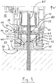
- two resilient latching hooks 29 are provided on the coupling section 27, as in FIG Sectional view according to Fig. 3 can be seen.
- the latching hooks 29 are arranged in opposite directions as shown and engage behind respective profile projections 30 of the window frame 11.
- the coupling section 27 is supported on the border 20 of the building opening 15 via a first threaded spindle 31, a first spindle nut 32 interacting with it, a second threaded spindle 33, a second spindle nut 34 interacting with this and a contact section 35.
- the contact section 35 is a support plate 37 with a flat contact surface 38.
- a spherical head 39 is formed on the support plate 37 and is received in a spherical head receptacle 40 of the spacer element 19.
- the coupling section 27 and the contact section 35 are thus connected to one another via a ball joint 41.
- the ball head receptacle 40 is formed in that component which also carries the first threaded spindle 31.
- the first spindle nut 32 is formed in one piece with the second threaded spindle 33.
- the second spindle nut 34 is slidably rotatably mounted on the coupling section 27.
- the first threaded spindle 31 interacts not only with the first spindle nut 32 but also with a lock nut 43 arranged adjacent to it.
- Fig. 3 shows a state in which the first spindle nut 32 is turned up to the stop on the first threaded spindle 31 and likewise the second spindle nut 34 is turned up to the stop on the second threaded spindle 33.
- the distance between the coupling section 27 and the contact section 35 predetermined by the spacer element 19 is minimal here.
- the first spindle nut 32 is rotated relative to the first threaded spindle 31 in such a way that it moves away from the stop, the distance between the coupling section 27 and the contact section 35 is increased and, accordingly, a displacement occurs of the window frame 11 relative to the border 20 of the building opening 15 in an adjustment direction V.
- the second spindle nut 34 is rotated relative to the second threaded spindle 33 away from the stop, the window frame 11 is displaced relative to the border 20 of the building opening 15 in the adjustment direction V.
- the first threaded spindle 31 and the first spindle nut 32 have a regular thread, while the second threaded spindle 33 and the second spindle nut 34 have a fine thread.
- the first spindle nut 32 can be rotated for a coarse displacement of the window frame 11 and the second spindle nut 34 can be rotated for a fine displacement of the window frame 11.
- the turning of the spindle nuts 32, 34 can be done directly and manually and in particular without tools, since the spindle nuts 32, 34 have respective actuating sections 44, 45 with grip features 46 ( Fig. 2 ) exhibit.
- the lock nut 43 has a circumferential corrugation 48.
- the window 10 When positioning the window 10 within the building opening 15, a user can initially carry out a rough positioning by turning the first spindle nut 32 and then fix the position of the first spindle nut 32 by means of the lock nut 43. He can then turn the second spindle nut 34 for fine positioning, an undesired turning of the first spindle nut 32 due to the counter nut 43 being prevented.
- the first spindle nut 32, the lock nut 43 and the second spindle nut 34 have reference signs 47 ( Fig. 2 ) are provided, which clarify the sequence of the work steps when positioning.
- the spacer element 19 is provided with a passage 80 for a screw 81.
- all components of the spacer element 19, in particular the coupling section 27, the first threaded spindle 31, the first spindle nut 32, the second threaded spindle 33, the second spindle nut 34, the lock nut 43 and the support plate 37 are made from a plastic, in particular from regranulate .
- the spacer element 19 can thus be manufactured particularly inexpensively, so that it is suitable for use as a disposable item.
- the Figures 4 to 6 show an alternative embodiment of a spacer element 49 which is constructed similarly to that in FIGS Figs. 1 to 3 spacer element 19 shown, but is designed for a lower overall height.
- the coupling section 57 has a shaft 59 which can be inserted into a shaft receptacle 58 provided on the frame 11 ( Fig. 6 ) is trained.
- the shaft 57 has a cylindrical jacket surface 60.
- Two resilient locking tongues 61 protrude from this ( Fig. 4 ).
- the resilient latching tongues 61 enable the coupling section 57 to snap into the shaft receptacle 58.
- the spacer element 49 shown also has a first threaded spindle 31, a first spindle nut 32 cooperating with this, a second threaded spindle 33, a second spindle nut 34 cooperating with this, a lock nut 43 and a contact section 35 in the form of a support plate 37.
- the first threaded spindle 31 and the first spindle nut 32 have a fine thread
- the second threaded spindle 33 and the second spindle nut 34 have a regular thread.
- the first threaded spindle 31 is formed in one piece with the support plate 37.
- the second spindle nut 34 is also formed in one piece with the shaft 59.
- the first spindle nut 32, the lock nut 43 and the second spindle nut 34 have respective actuating sections 62, 63, 64 which are provided with edge profiles 68. This enables rotation by means of a tool such as an open-end wrench. Reference signs 47 are also provided. The adjustment of the second spindle nut 34 must be carried out before the coupling section 57 is attached to the window 10.
- the overall height of the Figures 4 to 6 The spacer element 49 shown is reduced in that the coupling section 57 is partially arranged within the frame 11 when the window 10 is installed.
- the edge profiles 68 only require a low overall height.
- Fig. 7 shows another embodiment of a spacer element 69 of a positioning device 17 according to the invention.
- This is largely like the spacer element 49 according to FIG Figures 4 to 6 designed, but a form-fit feature 83 in the form of a hexagon socket profile is formed on the first threaded spindle 31, which is accessible through a recess 85 of the coupling section 57. Since a corresponding recess 87 is also provided in the window frame 11, the first threaded spindle 31 can still be rotated by means of a tool 88 if lateral access to the gap between the window frame 11 and the building opening 15 is no longer possible.
- Each of the two inclination testing devices 25 comprises a strip-shaped base body 70 which is preferably made from a plastic, in particular from a regranulate. This has a flat contact surface 71 for the application of the base body 70 to an outer surface of the window frame 11. At the contact surface 71 are in Fig. 1 Not visible fastening means arranged, which are in particular similar locking hooks as those in Fig. 3 for the spacer element 19 shown Locking hook 29 can act.
- the inclination testing device 25 can be detachably attached to the frame 11 by means of the fastening means.
- Two vials 75 are integrated into the base body 70 and are aligned offset from one another by 90 °. During the positioning of the window 10 in the building opening 15, the inclination of the window 10 can thus be continuously checked without a spirit level having to be applied to the frame 11 and held on it. Since the inclination testing devices 25 are composed of inexpensive components, it is not absolutely necessary to remove them from the frame 11 before screwing and foaming the window 10. However, reuse of the inclination testing devices 25 may be desirable depending on the application. In principle, it is also possible to use a digital inclination indicator or the like instead of one or more vials 75.
- the invention enables a considerably simplified installation of windows 10 and doors in building openings 15, a particular advantage being that when a window 10 with attached spacer elements 19, 49, 69 and inclination testing devices 25 is delivered, in principle no own material and no own equipment must be provided by the fitter.
Claims (10)
- Dispositif (17) pour positionner une fenêtre (10) ou une porte dans une ouverture de bâtiment (15), comprenant au moins un élément d'écartement (19, 49, 69) qui présente une portion d'accouplement (27, 67) pour l'accouplement à la fenêtre (10) ou à la porte et une portion d'appui (35) réalisée pour s'appuyer contre un rebord (20) de l'ouverture de bâtiment (15), dans lequel
un dispositif de réglage est prévu pour un déplacement de la fenêtre (10) ou de la porte à l'intérieur de l'ouverture de bâtiment (15), au moyen duquel la portion d'appui (35) peut être déplacée par rapport à la portion d'accouplement (27, 57) dans une direction de réglage (V) et en sens opposé à celle-ci,
le dispositif de réglage présente une première broche filetée (31) s'étendant le long de la direction de réglage (V), qui peut s'appuyer contre la portion d'accouplement (27, 57) ou contre la portion d'appui (35) dans la direction de réglage (V) ou en sens opposé à celle-ci et qui coopère avec un premier écrou de broche (32) qui peut s'appuyer en sens opposé contre l'autre élément parmi la portion d'accouplement (27, 57) et la portion d'appui (35), caractérisé en ce que
le dispositif de réglage comprend une second broche filetée (33) qui s'étend le long de la direction de réglage (V) et qui coopère avec un second écrou de broche (34) de telle sorte que la portion d'appui (35) peut être déplacée par rapport à la portion d'accouplement (27, 57) dans la direction de réglage (V) et en sens opposé à celle-ci aussi bien par une rotation du premier écrou de broche (32) par rapport à la première broche filetée (31) que par une rotation du second écrou de broche (34) par rapport à la seconde broche filetée (33),
la première broche filetée (31) et la seconde broche filetée (33) présentant différents pas de filetage. - Dispositif selon la revendication 1,
caractérisé en ce que
une portion d'actionnement (44) est prévue sur la première broche filetée (31) et/ou sur le premier écrou de broche (32) pour une rotation manuelle directe de la première broche filetée (31) par rapport au premier écrou de broche (32) par l'intermédiaire d'un utilisateur. - Dispositif selon la revendication 2,
caractérisé en ce que
la portion d'actionnement (44) présente un élément de préhension (46) et/ou un élément de coopération de forme (68), en particulier une cannelure et/ou un profilé polygonal,
et/ou en ce que
la portion d'actionnement (44) est réalisée d'un seul tenant avec la première broche filetée (31) ou avec le premier écrou de broche (32). - Dispositif selon l'une au moins des revendications précédentes,
caractérisé en ce que
la portion de butée (35) comprend une plaque de support (37) et/ou en ce que
la première broche filetée (31) coopère avec un écrou de blocage (43) prévu pour immobiliser le premier écrou de broche (32). - Dispositif selon l'une au moins des revendications précédentes,
caractérisé en ce que
la seconde broche filetée (33) est couplée solidairement en rotation au premier écrou de broche (32) et est de préférence réalisée d'un seul tenant avec celui-ci, ou en ce que
la première broche filetée (31) est couplée solidairement en rotation au second écrou de broche (34) et est de préférence réalisée d'un seul tenant avec celui-ci. - Dispositif selon la revendication 5,
caractérisé en ce que
le premier écrou de broche (32) et/ou le second écrou de broche (34) est monté de manière à pouvoir tourner par rapport à la portion d'accouplement (27, 57). - Dispositif selon l'une des revendications précédentes,
caractérisé en ce que
la première broche filetée (31) présente un filetage à pas gros, et la seconde broche filetée (33) présente un filetage à pas fin, ou inversement. - Dispositif selon l'une au moins des revendications précédentes,
caractérisé en ce que
la portion d'accouplement (27, 57), la portion d'appui (35), la première broche filetée (31) et/ou le premier écrou de broche (32) est/sont fabriqué(e)(s) en matière plastique, en particulier en matière rebroyée. - Dispositif selon l'une au moins des revendications précédentes,
caractérisé en ce que
la portion d'accouplement (27, 57) est réalisée pour une liaison par coopération de forme ou de force, en particulier pour une liaison par enclenchement, par encliquetage ou par clipsage, avec un profilé de cadre dormant de la fenêtre (10) ou de la porte, et/ou en ce que
la portion d'accouplement (27, 57) présente au moins un élément d'enclenchement élastique (29, 61) destiné engager par l'arrière une saillie de profilé (30) prévue sur le profilé de cadre dormant, et/ou en ce que
la portion d'accouplement (27, 57) présente une tige (59) qui est réalisée pour être enfichée dans un logement (58) prévu sur le profilé de cadre dormant. - Dispositif selon l'une au moins des revendications précédentes,
caractérisé en ce que
l'élément d'écartement (19) présente un passage (80) pour un moyen de fixation (81), passage qui s'étend depuis la portion d'accouplement (27) jusqu'à la portion d'appui (35) à travers tout l'élément d'écartement (19), et/ou en ce que
un élément de coopération de forme (83), en particulier un profilé polygonal, est réalisé sur la première broche filetée (31) ou sur le premier écrou de broche (32), élément qui est accessible à travers un évidement (85) de la portion d'accouplement (27), et/ou en ce que
la portion d'accouplement (27) et la portion d'appui (35) sont reliées entre elles par une articulation (41), en particulier par une articulation à rotule.
Applications Claiming Priority (1)
| Application Number | Priority Date | Filing Date | Title |
|---|---|---|---|
| DE102017127119.8A DE102017127119A1 (de) | 2017-11-17 | 2017-11-17 | Vorrichtung zum Positionieren eines Fensters oder einer Tür |
Publications (3)
| Publication Number | Publication Date |
|---|---|
| EP3486420A2 EP3486420A2 (fr) | 2019-05-22 |
| EP3486420A3 EP3486420A3 (fr) | 2019-08-14 |
| EP3486420B1 true EP3486420B1 (fr) | 2020-12-30 |
Family
ID=64316395
Family Applications (1)
| Application Number | Title | Priority Date | Filing Date |
|---|---|---|---|
| EP18206244.8A Active EP3486420B1 (fr) | 2017-11-17 | 2018-11-14 | Procédé de positionnement d'une fenêtre ou d'une porte |
Country Status (2)
| Country | Link |
|---|---|
| EP (1) | EP3486420B1 (fr) |
| DE (1) | DE102017127119A1 (fr) |
Cited By (1)
| Publication number | Priority date | Publication date | Assignee | Title |
|---|---|---|---|---|
| CN112983191A (zh) * | 2021-03-19 | 2021-06-18 | 北京润亚建设工程发展有限责任公司 | 一种门窗安装结构 |
Families Citing this family (3)
| Publication number | Priority date | Publication date | Assignee | Title |
|---|---|---|---|---|
| DE102019116542A1 (de) * | 2019-06-18 | 2020-12-24 | SCHÜCO International KG | Abstandshalter, Montageanordnung und Verfahren zur Montage eines Beschlages an einem Profil |
| CN110552588B (zh) * | 2019-09-20 | 2020-06-09 | 云南艺康装饰工程有限公司 | 一种门窗固定安装施工工艺 |
| CN114150978A (zh) * | 2021-12-16 | 2022-03-08 | 天津木艺家新材料科技有限公司 | 一种门窗及门窗安装方法 |
Family Cites Families (17)
| Publication number | Priority date | Publication date | Assignee | Title |
|---|---|---|---|---|
| US4910876A (en) * | 1989-09-07 | 1990-03-27 | Channell John F | Level attachment |
| DE4421127A1 (de) * | 1994-06-16 | 1995-12-21 | Peter Pfeifer | Fensterrahmen |
| DE19531862A1 (de) * | 1995-08-30 | 1997-03-06 | Peter Pfeifer | Justiereinrichtung |
| DE19603413A1 (de) * | 1996-01-31 | 1997-08-07 | Hawik Innovative Baubeschlaege | Höhenverstelleinrichtung für einen unteren Abschluß von Türen oder Fenstern mit angesetzter Verbreiterung |
| WO1998001647A1 (fr) * | 1996-07-04 | 1998-01-15 | Soederstroem Kurt | Dispositif de fixation pour fixer de maniere reglable un cadre dans une ouverture de mur |
| DE29709238U1 (de) * | 1997-05-27 | 1997-10-16 | Schermann Hans | Höhenregulierbares Befestigungssystem für bodenhohe Tür- und Fensterelemente |
| DE19722531A1 (de) * | 1997-05-30 | 1998-12-03 | Peter Willrich | Höhenverstelleinrichtung II |
| JPH1113346A (ja) * | 1997-06-25 | 1999-01-19 | Fukuju Oshima | 建具枠の垂直水平出し器 |
| DE29715991U1 (de) * | 1997-09-05 | 1997-11-20 | Glusa Dieter | Befestigungs- und Verkleidungssystem für Fensterelemente aus Kunststoff |
| DE19808194A1 (de) * | 1998-02-27 | 1999-09-09 | Fabricius | Justier- und Befestigungseinrichtung für den Fenstereinbau i Bauwerksöffnungen |
| DE19860269A1 (de) * | 1998-12-24 | 2000-06-29 | Bessey & Sohn | Montagekeil |
| US6874286B2 (en) * | 2000-03-07 | 2005-04-05 | Mtd Industries Ltd. | Window frame construction system and connector units for use therein |
| DE20311512U1 (de) * | 2003-07-25 | 2004-11-25 | Sfs Intec Holding Ag | Konsole zum Abstützen und Befestigen von Fenster- oder Türrahmen an der Begrenzung einer Wandöffnung |
| DE20311513U1 (de) * | 2003-07-25 | 2004-11-25 | Sfs Intec Holding Ag | Vorrichtung zum Abstützen und Befestigen von Fenster- oder Türrahmen an der Begrenzung einer Wandöffnung |
| DE202004007226U1 (de) * | 2004-05-06 | 2005-09-15 | Buschmann Thomas | Vorrichtung zur Montage eines Rahmens |
| DE202006012518U1 (de) * | 2006-08-14 | 2006-10-12 | Kneisen, Waldemar | Vorrichtung zum Justieren eines Baukörpers |
| DE102009056587A1 (de) * | 2009-11-27 | 2011-06-01 | Thomas Gerlach | Türzargenausrichter |
-
2017
- 2017-11-17 DE DE102017127119.8A patent/DE102017127119A1/de active Pending
-
2018
- 2018-11-14 EP EP18206244.8A patent/EP3486420B1/fr active Active
Non-Patent Citations (1)
| Title |
|---|
| None * |
Cited By (1)
| Publication number | Priority date | Publication date | Assignee | Title |
|---|---|---|---|---|
| CN112983191A (zh) * | 2021-03-19 | 2021-06-18 | 北京润亚建设工程发展有限责任公司 | 一种门窗安装结构 |
Also Published As
| Publication number | Publication date |
|---|---|
| EP3486420A2 (fr) | 2019-05-22 |
| EP3486420A3 (fr) | 2019-08-14 |
| DE102017127119A1 (de) | 2019-05-23 |
Similar Documents
| Publication | Publication Date | Title |
|---|---|---|
| EP3486420B1 (fr) | Procédé de positionnement d'une fenêtre ou d'une porte | |
| EP2720907B1 (fr) | Dispositif de fixation comprenant un compensateur de tolérance | |
| EP1709270B1 (fr) | Fixation de pinces pour le montage de dispositifs de ferrures, tels que fermetures, elements de charniere, poignees dans des passages au travers d'une paroi mince | |
| EP2851497B1 (fr) | Dispositif de montage réglable pour un élément coulissant et dispositif coulissant | |
| EP3445935B1 (fr) | Installation de porte coulissante | |
| EP2742199B1 (fr) | Système de fixation pour fixer une pièce sur une rainure d'une fenêtre, d'une porte ou analogue | |
| DE10354117B4 (de) | Toleranzausgleichselement | |
| DE102007017453B4 (de) | Drehöffnungsbegrenzungsvorrichtung für einen Flügel eines Fensters oder dergleichen | |
| EP3425155B1 (fr) | Dispositif de protection anti-pince doigt pour une porte | |
| DE202009013488U1 (de) | Vorrichtung zum Fixieren eines Baukörpers in einer Gebäudeöffnung | |
| EP3150786A1 (fr) | Liaison articulée | |
| DE19715496C1 (de) | Justierelement | |
| DE202016106504U1 (de) | Montagewerkzeug für die Montage einer Schaltschranktür an einem Schaltschrankgehäuse und eine entsprechende Schaltschrankanordnung | |
| EP1035294B1 (fr) | Ensemble de montage d'un meneau dans un encadrement | |
| EP2031175B1 (fr) | Elément latéral pour un boîtier de store | |
| DE4238725A1 (de) | Kühlergitter | |
| EP3363969A1 (fr) | Poignée d'actionnement | |
| EP1793067B1 (fr) | Ferrure pour portes, fenêtres ou similaires | |
| EP3269903B1 (fr) | Garniture à rosette pour poussoir de portes ou de fenêtres | |
| EP2149660B1 (fr) | Boîtier d'entraînement pour une ferrure de bielle | |
| EP3208415B1 (fr) | Dispositif d'ajustage | |
| EP1922467B1 (fr) | Charniere pour portes, fenetres ou elements similaires | |
| EP1820927B1 (fr) | Module de douille | |
| EP3029241A1 (fr) | Ferrure d'angle à force de serrage accrue | |
| DE202006006688U1 (de) | Befestigung mit Verlierschutz für ein Befestigungsmittel |
Legal Events
| Date | Code | Title | Description |
|---|---|---|---|
| PUAI | Public reference made under article 153(3) epc to a published international application that has entered the european phase |
Free format text: ORIGINAL CODE: 0009012 |
|
| STAA | Information on the status of an ep patent application or granted ep patent |
Free format text: STATUS: THE APPLICATION HAS BEEN PUBLISHED |
|
| AK | Designated contracting states |
Kind code of ref document: A2 Designated state(s): AL AT BE BG CH CY CZ DE DK EE ES FI FR GB GR HR HU IE IS IT LI LT LU LV MC MK MT NL NO PL PT RO RS SE SI SK SM TR |
|
| AX | Request for extension of the european patent |
Extension state: BA ME |
|
| PUAL | Search report despatched |
Free format text: ORIGINAL CODE: 0009013 |
|
| AK | Designated contracting states |
Kind code of ref document: A3 Designated state(s): AL AT BE BG CH CY CZ DE DK EE ES FI FR GB GR HR HU IE IS IT LI LT LU LV MC MK MT NL NO PL PT RO RS SE SI SK SM TR |
|
| AX | Request for extension of the european patent |
Extension state: BA ME |
|
| RIC1 | Information provided on ipc code assigned before grant |
Ipc: F16B 5/02 20060101ALI20190709BHEP Ipc: E06B 1/60 20060101AFI20190709BHEP Ipc: F16B 21/08 20060101ALI20190709BHEP Ipc: E04F 21/00 20060101ALI20190709BHEP |
|
| STAA | Information on the status of an ep patent application or granted ep patent |
Free format text: STATUS: REQUEST FOR EXAMINATION WAS MADE |
|
| 17P | Request for examination filed |
Effective date: 20191023 |
|
| RBV | Designated contracting states (corrected) |
Designated state(s): AL AT BE BG CH CY CZ DE DK EE ES FI FR GB GR HR HU IE IS IT LI LT LU LV MC MK MT NL NO PL PT RO RS SE SI SK SM TR |
|
| GRAP | Despatch of communication of intention to grant a patent |
Free format text: ORIGINAL CODE: EPIDOSNIGR1 |
|
| STAA | Information on the status of an ep patent application or granted ep patent |
Free format text: STATUS: GRANT OF PATENT IS INTENDED |
|
| INTG | Intention to grant announced |
Effective date: 20200806 |
|
| GRAS | Grant fee paid |
Free format text: ORIGINAL CODE: EPIDOSNIGR3 |
|
| GRAA | (expected) grant |
Free format text: ORIGINAL CODE: 0009210 |
|
| STAA | Information on the status of an ep patent application or granted ep patent |
Free format text: STATUS: THE PATENT HAS BEEN GRANTED |
|
| AK | Designated contracting states |
Kind code of ref document: B1 Designated state(s): AL AT BE BG CH CY CZ DE DK EE ES FI FR GB GR HR HU IE IS IT LI LT LU LV MC MK MT NL NO PL PT RO RS SE SI SK SM TR |
|
| REG | Reference to a national code |
Ref country code: GB Ref legal event code: FG4D Free format text: NOT ENGLISH |
|
| REG | Reference to a national code |
Ref country code: AT Ref legal event code: REF Ref document number: 1350085 Country of ref document: AT Kind code of ref document: T Effective date: 20210115 |
|
| REG | Reference to a national code |
Ref country code: DE Ref legal event code: R096 Ref document number: 502018003469 Country of ref document: DE |
|
| REG | Reference to a national code |
Ref country code: IE Ref legal event code: FG4D Free format text: LANGUAGE OF EP DOCUMENT: GERMAN |
|
| PG25 | Lapsed in a contracting state [announced via postgrant information from national office to epo] |
Ref country code: NO Free format text: LAPSE BECAUSE OF FAILURE TO SUBMIT A TRANSLATION OF THE DESCRIPTION OR TO PAY THE FEE WITHIN THE PRESCRIBED TIME-LIMIT Effective date: 20210330 Ref country code: GR Free format text: LAPSE BECAUSE OF FAILURE TO SUBMIT A TRANSLATION OF THE DESCRIPTION OR TO PAY THE FEE WITHIN THE PRESCRIBED TIME-LIMIT Effective date: 20210331 Ref country code: RS Free format text: LAPSE BECAUSE OF FAILURE TO SUBMIT A TRANSLATION OF THE DESCRIPTION OR TO PAY THE FEE WITHIN THE PRESCRIBED TIME-LIMIT Effective date: 20201230 Ref country code: FI Free format text: LAPSE BECAUSE OF FAILURE TO SUBMIT A TRANSLATION OF THE DESCRIPTION OR TO PAY THE FEE WITHIN THE PRESCRIBED TIME-LIMIT Effective date: 20201230 |
|
| PG25 | Lapsed in a contracting state [announced via postgrant information from national office to epo] |
Ref country code: LV Free format text: LAPSE BECAUSE OF FAILURE TO SUBMIT A TRANSLATION OF THE DESCRIPTION OR TO PAY THE FEE WITHIN THE PRESCRIBED TIME-LIMIT Effective date: 20201230 Ref country code: SE Free format text: LAPSE BECAUSE OF FAILURE TO SUBMIT A TRANSLATION OF THE DESCRIPTION OR TO PAY THE FEE WITHIN THE PRESCRIBED TIME-LIMIT Effective date: 20201230 Ref country code: BG Free format text: LAPSE BECAUSE OF FAILURE TO SUBMIT A TRANSLATION OF THE DESCRIPTION OR TO PAY THE FEE WITHIN THE PRESCRIBED TIME-LIMIT Effective date: 20210330 |
|
| REG | Reference to a national code |
Ref country code: NL Ref legal event code: MP Effective date: 20201230 |
|
| PG25 | Lapsed in a contracting state [announced via postgrant information from national office to epo] |
Ref country code: HR Free format text: LAPSE BECAUSE OF FAILURE TO SUBMIT A TRANSLATION OF THE DESCRIPTION OR TO PAY THE FEE WITHIN THE PRESCRIBED TIME-LIMIT Effective date: 20201230 |
|
| REG | Reference to a national code |
Ref country code: LT Ref legal event code: MG9D |
|
| PG25 | Lapsed in a contracting state [announced via postgrant information from national office to epo] |
Ref country code: LT Free format text: LAPSE BECAUSE OF FAILURE TO SUBMIT A TRANSLATION OF THE DESCRIPTION OR TO PAY THE FEE WITHIN THE PRESCRIBED TIME-LIMIT Effective date: 20201230 Ref country code: PT Free format text: LAPSE BECAUSE OF FAILURE TO SUBMIT A TRANSLATION OF THE DESCRIPTION OR TO PAY THE FEE WITHIN THE PRESCRIBED TIME-LIMIT Effective date: 20210430 Ref country code: RO Free format text: LAPSE BECAUSE OF FAILURE TO SUBMIT A TRANSLATION OF THE DESCRIPTION OR TO PAY THE FEE WITHIN THE PRESCRIBED TIME-LIMIT Effective date: 20201230 Ref country code: SK Free format text: LAPSE BECAUSE OF FAILURE TO SUBMIT A TRANSLATION OF THE DESCRIPTION OR TO PAY THE FEE WITHIN THE PRESCRIBED TIME-LIMIT Effective date: 20201230 Ref country code: EE Free format text: LAPSE BECAUSE OF FAILURE TO SUBMIT A TRANSLATION OF THE DESCRIPTION OR TO PAY THE FEE WITHIN THE PRESCRIBED TIME-LIMIT Effective date: 20201230 Ref country code: CZ Free format text: LAPSE BECAUSE OF FAILURE TO SUBMIT A TRANSLATION OF THE DESCRIPTION OR TO PAY THE FEE WITHIN THE PRESCRIBED TIME-LIMIT Effective date: 20201230 |
|
| PG25 | Lapsed in a contracting state [announced via postgrant information from national office to epo] |
Ref country code: PL Free format text: LAPSE BECAUSE OF FAILURE TO SUBMIT A TRANSLATION OF THE DESCRIPTION OR TO PAY THE FEE WITHIN THE PRESCRIBED TIME-LIMIT Effective date: 20201230 |
|
| PG25 | Lapsed in a contracting state [announced via postgrant information from national office to epo] |
Ref country code: IS Free format text: LAPSE BECAUSE OF FAILURE TO SUBMIT A TRANSLATION OF THE DESCRIPTION OR TO PAY THE FEE WITHIN THE PRESCRIBED TIME-LIMIT Effective date: 20210430 |
|
| REG | Reference to a national code |
Ref country code: DE Ref legal event code: R097 Ref document number: 502018003469 Country of ref document: DE |
|
| PG25 | Lapsed in a contracting state [announced via postgrant information from national office to epo] |
Ref country code: AL Free format text: LAPSE BECAUSE OF FAILURE TO SUBMIT A TRANSLATION OF THE DESCRIPTION OR TO PAY THE FEE WITHIN THE PRESCRIBED TIME-LIMIT Effective date: 20201230 |
|
| PLBE | No opposition filed within time limit |
Free format text: ORIGINAL CODE: 0009261 |
|
| STAA | Information on the status of an ep patent application or granted ep patent |
Free format text: STATUS: NO OPPOSITION FILED WITHIN TIME LIMIT |
|
| PG25 | Lapsed in a contracting state [announced via postgrant information from national office to epo] |
Ref country code: DK Free format text: LAPSE BECAUSE OF FAILURE TO SUBMIT A TRANSLATION OF THE DESCRIPTION OR TO PAY THE FEE WITHIN THE PRESCRIBED TIME-LIMIT Effective date: 20201230 |
|
| 26N | No opposition filed |
Effective date: 20211001 |
|
| PG25 | Lapsed in a contracting state [announced via postgrant information from national office to epo] |
Ref country code: ES Free format text: LAPSE BECAUSE OF FAILURE TO SUBMIT A TRANSLATION OF THE DESCRIPTION OR TO PAY THE FEE WITHIN THE PRESCRIBED TIME-LIMIT Effective date: 20201230 |
|
| PG25 | Lapsed in a contracting state [announced via postgrant information from national office to epo] |
Ref country code: SI Free format text: LAPSE BECAUSE OF FAILURE TO SUBMIT A TRANSLATION OF THE DESCRIPTION OR TO PAY THE FEE WITHIN THE PRESCRIBED TIME-LIMIT Effective date: 20201230 |
|
| PG25 | Lapsed in a contracting state [announced via postgrant information from national office to epo] |
Ref country code: IS Free format text: LAPSE BECAUSE OF FAILURE TO SUBMIT A TRANSLATION OF THE DESCRIPTION OR TO PAY THE FEE WITHIN THE PRESCRIBED TIME-LIMIT Effective date: 20210430 |
|
| PG25 | Lapsed in a contracting state [announced via postgrant information from national office to epo] |
Ref country code: MC Free format text: LAPSE BECAUSE OF FAILURE TO SUBMIT A TRANSLATION OF THE DESCRIPTION OR TO PAY THE FEE WITHIN THE PRESCRIBED TIME-LIMIT Effective date: 20201230 |
|
| REG | Reference to a national code |
Ref country code: CH Ref legal event code: PL |
|
| PG25 | Lapsed in a contracting state [announced via postgrant information from national office to epo] |
Ref country code: LU Free format text: LAPSE BECAUSE OF NON-PAYMENT OF DUE FEES Effective date: 20211114 Ref country code: BE Free format text: LAPSE BECAUSE OF NON-PAYMENT OF DUE FEES Effective date: 20211130 |
|
| REG | Reference to a national code |
Ref country code: BE Ref legal event code: MM Effective date: 20211130 |
|
| PG25 | Lapsed in a contracting state [announced via postgrant information from national office to epo] |
Ref country code: LI Free format text: LAPSE BECAUSE OF NON-PAYMENT OF DUE FEES Effective date: 20211130 Ref country code: CH Free format text: LAPSE BECAUSE OF NON-PAYMENT OF DUE FEES Effective date: 20211130 |
|
| PG25 | Lapsed in a contracting state [announced via postgrant information from national office to epo] |
Ref country code: IE Free format text: LAPSE BECAUSE OF NON-PAYMENT OF DUE FEES Effective date: 20211114 |
|
| PG25 | Lapsed in a contracting state [announced via postgrant information from national office to epo] |
Ref country code: NL Free format text: LAPSE BECAUSE OF NON-PAYMENT OF DUE FEES Effective date: 20201230 Ref country code: CY Free format text: LAPSE BECAUSE OF FAILURE TO SUBMIT A TRANSLATION OF THE DESCRIPTION OR TO PAY THE FEE WITHIN THE PRESCRIBED TIME-LIMIT Effective date: 20201230 |
|
| GBPC | Gb: european patent ceased through non-payment of renewal fee |
Effective date: 20221114 |
|
| PG25 | Lapsed in a contracting state [announced via postgrant information from national office to epo] |
Ref country code: SM Free format text: LAPSE BECAUSE OF FAILURE TO SUBMIT A TRANSLATION OF THE DESCRIPTION OR TO PAY THE FEE WITHIN THE PRESCRIBED TIME-LIMIT Effective date: 20201230 Ref country code: HU Free format text: LAPSE BECAUSE OF FAILURE TO SUBMIT A TRANSLATION OF THE DESCRIPTION OR TO PAY THE FEE WITHIN THE PRESCRIBED TIME-LIMIT; INVALID AB INITIO Effective date: 20181114 |
|
| PG25 | Lapsed in a contracting state [announced via postgrant information from national office to epo] |
Ref country code: GB Free format text: LAPSE BECAUSE OF NON-PAYMENT OF DUE FEES Effective date: 20221114 |
|
| PGFP | Annual fee paid to national office [announced via postgrant information from national office to epo] |
Ref country code: IT Payment date: 20231124 Year of fee payment: 6 Ref country code: FR Payment date: 20231120 Year of fee payment: 6 Ref country code: DE Payment date: 20231121 Year of fee payment: 6 Ref country code: AT Payment date: 20231121 Year of fee payment: 6 |
|
| PG25 | Lapsed in a contracting state [announced via postgrant information from national office to epo] |
Ref country code: MK Free format text: LAPSE BECAUSE OF FAILURE TO SUBMIT A TRANSLATION OF THE DESCRIPTION OR TO PAY THE FEE WITHIN THE PRESCRIBED TIME-LIMIT Effective date: 20201230 |