EP3485992B1 - Verfahren zum umformen eines blechrohlings, z.b. einer platine oder eines hohlkörperrohlings als werkstück in einem umformwerkzeug - Google Patents
Verfahren zum umformen eines blechrohlings, z.b. einer platine oder eines hohlkörperrohlings als werkstück in einem umformwerkzeug Download PDFInfo
- Publication number
- EP3485992B1 EP3485992B1 EP18201134.6A EP18201134A EP3485992B1 EP 3485992 B1 EP3485992 B1 EP 3485992B1 EP 18201134 A EP18201134 A EP 18201134A EP 3485992 B1 EP3485992 B1 EP 3485992B1
- Authority
- EP
- European Patent Office
- Prior art keywords
- workpiece
- forming
- cavity
- accordance
- heat treatment
- Prior art date
- Legal status (The legal status is an assumption and is not a legal conclusion. Google has not performed a legal analysis and makes no representation as to the accuracy of the status listed.)
- Active
Links
- 238000000034 method Methods 0.000 title claims description 61
- 239000002184 metal Substances 0.000 title claims description 8
- 239000000463 material Substances 0.000 claims description 45
- 238000010438 heat treatment Methods 0.000 claims description 16
- 238000001816 cooling Methods 0.000 claims description 7
- 230000015572 biosynthetic process Effects 0.000 claims description 4
- 238000007789 sealing Methods 0.000 claims 1
- 238000000137 annealing Methods 0.000 description 24
- 229910000831 Steel Inorganic materials 0.000 description 4
- 239000010959 steel Substances 0.000 description 4
- 229910045601 alloy Inorganic materials 0.000 description 2
- 239000000956 alloy Substances 0.000 description 2
- 238000003825 pressing Methods 0.000 description 2
- 230000004069 differentiation Effects 0.000 description 1
- 230000000694 effects Effects 0.000 description 1
- 238000005516 engineering process Methods 0.000 description 1
- 238000003754 machining Methods 0.000 description 1
- 238000004519 manufacturing process Methods 0.000 description 1
- 229910000734 martensite Inorganic materials 0.000 description 1
- BASFCYQUMIYNBI-UHFFFAOYSA-N platinum Chemical compound [Pt] BASFCYQUMIYNBI-UHFFFAOYSA-N 0.000 description 1
- 239000002994 raw material Substances 0.000 description 1
- 230000035939 shock Effects 0.000 description 1
- 230000037303 wrinkles Effects 0.000 description 1
Images


Classifications
-
- B—PERFORMING OPERATIONS; TRANSPORTING
- B21—MECHANICAL METAL-WORKING WITHOUT ESSENTIALLY REMOVING MATERIAL; PUNCHING METAL
- B21D—WORKING OR PROCESSING OF SHEET METAL OR METAL TUBES, RODS OR PROFILES WITHOUT ESSENTIALLY REMOVING MATERIAL; PUNCHING METAL
- B21D22/00—Shaping without cutting, by stamping, spinning, or deep-drawing
- B21D22/02—Stamping using rigid devices or tools
- B21D22/022—Stamping using rigid devices or tools by heating the blank or stamping associated with heat treatment
-
- B—PERFORMING OPERATIONS; TRANSPORTING
- B21—MECHANICAL METAL-WORKING WITHOUT ESSENTIALLY REMOVING MATERIAL; PUNCHING METAL
- B21D—WORKING OR PROCESSING OF SHEET METAL OR METAL TUBES, RODS OR PROFILES WITHOUT ESSENTIALLY REMOVING MATERIAL; PUNCHING METAL
- B21D22/00—Shaping without cutting, by stamping, spinning, or deep-drawing
- B21D22/20—Deep-drawing
- B21D22/208—Deep-drawing by heating the blank or deep-drawing associated with heat treatment
-
- B—PERFORMING OPERATIONS; TRANSPORTING
- B21—MECHANICAL METAL-WORKING WITHOUT ESSENTIALLY REMOVING MATERIAL; PUNCHING METAL
- B21D—WORKING OR PROCESSING OF SHEET METAL OR METAL TUBES, RODS OR PROFILES WITHOUT ESSENTIALLY REMOVING MATERIAL; PUNCHING METAL
- B21D22/00—Shaping without cutting, by stamping, spinning, or deep-drawing
- B21D22/20—Deep-drawing
- B21D22/30—Deep-drawing to finish articles formed by deep-drawing
-
- B—PERFORMING OPERATIONS; TRANSPORTING
- B21—MECHANICAL METAL-WORKING WITHOUT ESSENTIALLY REMOVING MATERIAL; PUNCHING METAL
- B21D—WORKING OR PROCESSING OF SHEET METAL OR METAL TUBES, RODS OR PROFILES WITHOUT ESSENTIALLY REMOVING MATERIAL; PUNCHING METAL
- B21D26/00—Shaping without cutting otherwise than using rigid devices or tools or yieldable or resilient pads, i.e. applying fluid pressure or magnetic forces
- B21D26/02—Shaping without cutting otherwise than using rigid devices or tools or yieldable or resilient pads, i.e. applying fluid pressure or magnetic forces by applying fluid pressure
- B21D26/021—Deforming sheet bodies
- B21D26/027—Means for controlling fluid parameters, e.g. pressure or temperature
-
- B—PERFORMING OPERATIONS; TRANSPORTING
- B21—MECHANICAL METAL-WORKING WITHOUT ESSENTIALLY REMOVING MATERIAL; PUNCHING METAL
- B21D—WORKING OR PROCESSING OF SHEET METAL OR METAL TUBES, RODS OR PROFILES WITHOUT ESSENTIALLY REMOVING MATERIAL; PUNCHING METAL
- B21D26/00—Shaping without cutting otherwise than using rigid devices or tools or yieldable or resilient pads, i.e. applying fluid pressure or magnetic forces
- B21D26/02—Shaping without cutting otherwise than using rigid devices or tools or yieldable or resilient pads, i.e. applying fluid pressure or magnetic forces by applying fluid pressure
- B21D26/033—Deforming tubular bodies
- B21D26/043—Means for controlling the axial pusher
-
- C—CHEMISTRY; METALLURGY
- C21—METALLURGY OF IRON
- C21D—MODIFYING THE PHYSICAL STRUCTURE OF FERROUS METALS; GENERAL DEVICES FOR HEAT TREATMENT OF FERROUS OR NON-FERROUS METALS OR ALLOYS; MAKING METAL MALLEABLE, e.g. BY DECARBURISATION OR TEMPERING
- C21D8/00—Modifying the physical properties by deformation combined with, or followed by, heat treatment
- C21D8/02—Modifying the physical properties by deformation combined with, or followed by, heat treatment during manufacturing of plates or strips
- C21D8/0247—Modifying the physical properties by deformation combined with, or followed by, heat treatment during manufacturing of plates or strips characterised by the heat treatment
-
- C—CHEMISTRY; METALLURGY
- C21—METALLURGY OF IRON
- C21D—MODIFYING THE PHYSICAL STRUCTURE OF FERROUS METALS; GENERAL DEVICES FOR HEAT TREATMENT OF FERROUS OR NON-FERROUS METALS OR ALLOYS; MAKING METAL MALLEABLE, e.g. BY DECARBURISATION OR TEMPERING
- C21D9/00—Heat treatment, e.g. annealing, hardening, quenching or tempering, adapted for particular articles; Furnaces therefor
- C21D9/46—Heat treatment, e.g. annealing, hardening, quenching or tempering, adapted for particular articles; Furnaces therefor for sheet metals
- C21D9/48—Heat treatment, e.g. annealing, hardening, quenching or tempering, adapted for particular articles; Furnaces therefor for sheet metals deep-drawing sheets
Definitions
- the present invention relates on the one hand to a method for forming a sheet metal blank, for. B. a board as a workpiece in a forming tool, z. B. a forming press, wherein the forming tool has at least one engraving and advantageously at least one hold-down device for fixing the workpiece to the engraving during the forming.
- the invention relates to a method for forming a hollow body blank as a workpiece in a forming tool, for. B. a forming press with in particular at least one locking device for the hollow body blank, wherein the forming tool has at least one engraving for receiving the hollow body blank during the forming process.
- Forming processes are sufficiently known from the prior art.
- the WO 2015/136299 A2 known to first heat a metallic workpiece to the solution heat treatment temperature range, and then in a further step to cool the workpiece down to the deformation temperature, to deform the workpiece, the workpiece continuing to cool in an uncontrolled manner during the deformation and the deformation material to solidify in an uncontrolled manner, which leads to a springback effect .
- the workpiece is then removed from the mold.
- the disadvantage of this known method is the relatively long cycle time, the non-optimal, too cold forming temperature and the springback, which affects compliance with the dead dance.
- the long cycle time is due to the unfavorable sequence of machining processes up to the actual forming, in particular the heating to the solution annealing temperature and the subsequent cooling before the forming, including the time for the workpiece to cool in the tool as well as the cooling during the forming process.
- the too rapid cooling of the blank during the forming process allows only low degrees of deformation, particularly with low A80% elongations of the workpiece, particularly with high-strength alloys and / or low wall thicknesses. As a result, tight radii and sharp edges cannot be represented, since the thinner the wall thickness of the blank or the workpiece, the faster it cools down after it has been inserted into the tool and that before it is completely formed.
- so-called superplastic forming is also state of the art.
- SPF superplastic forming
- Workpiece for example a blank or a hollow body, firmly clamped in the tool heated to the superplastic temperature, which is usually located in an oven.
- the blank is positively sealed between the two mold halves when it is closed, so that no material can flow into the engraving during the forming.
- the wall thickness of the workpiece in the engraving is undefined in relation to the location in the engraving. This means that at different points the wall thickness can have different, non-predictable thicknesses depending on the coefficients of friction or temperatures prevailing there. In this respect, the formation of the wall thickness in the engraving is more or less random.
- the object of the invention is to provide a remedy here.
- a method is to be provided with which short cycle times can be achieved during the forming process with an essentially predeterminable wall thickness of the workpiece.
- the method should be suitable for the deformation of high-strength alloys of any wall thickness and with the desired high degrees of deformation.
- the aim of the method is to produce workpieces with a predeterminable wall thickness and also those workpieces that are characterized by small radii, with the cycle times being kept as short as possible during the forming.
- a method for forming a blank as a workpiece in a forming tool in which the forming tool has at least one engraving or die and advantageously at least one hold-down device for fixing the workpiece to the engraving during the forming, is provided according to the invention, that the reshaping takes place in the solution annealing temperature range of the material of the workpiece to be reshaped, the tool being set to the workpiece-specific solution annealing temperature, the pressure of the hold-down device for fixing the workpiece to the engraving being selected so that material of the workpiece can flow into the engraving and / or whereby the material of the workpiece is actively pushed into the engraving, or the deformation takes place entirely without additional workpiece material in the engraving.
- the hold-down device can be advantageous in certain forming processes, for example in deep-drawing with a punch, the feed of material into the engraving being controllable through the hold-down device.
- the pressure or the pressing force on the workpiece between the hold-down device and the engraving is decisive for the question of whether and, if so, how much material from the workpiece can flow into the engraving.
- the invention for deforming a hollow body blank as a workpiece in a forming tool, in particular with at least one locking device for the hollow body blank, the forming tool having at least one engraving or die for receiving the hollow body blank during the forming process, the invention provides that the forming process takes place in the solution annealing temperature range of Material of the workpiece to be formed takes place, whereby the tool is set to the workpiece-specific solution annealing temperature, whereby the workpiece (the hollow body blank) is held by the locking device in such a way that material of the workpiece can flow in, and / or the material of the workpiece is actively pushed into the engraving, or that the deformation takes place on the basis of the material of the hollow body blank, which is located within the engraving.
- the essence of the invention is to heat the workpiece to be formed, for example the blank, to the solution annealing or austenitizing temperature, in order to then bring it to this temperature either after or during the solution annealing process or after the austenitization is complete Engraving to make the deformation.
- the workpiece had already undergone a solution annealing process or had been austenitized, to undertake the deformation in the tool, which is permanently heated to near the solution annealing temperature, in the area of optimal expansion of the workpiece material.
- the term "permanent" is intended to describe at least the period of time during the solution heat treatment and the forming.
- the temperature should advantageously be maintained during the daily production process, because then wear can be reduced, especially on the engraving. This is compared to constant heating and cooling of the forming tool, which leads to increased wear on the forming tool, because cooling is equivalent to a recurring thermal shock.
- solution annealing temperature in relation to steel is also understood to mean the austenitizing temperature.
- solution annealing temperature is a generic term for a special one Heat treatment at a temperature that also includes the austenitizing temperature for steel.
- the object of the method is to heat the workpiece to the solution annealing temperature range which is specifically intended for the material of the workpiece to be formed.
- the temperature is advantageously selected so that it enables solution annealing, but does not damage the material structure or, in the case of martensitic steels, for example, the temperature for austenitizing or solution annealing is above the AC3 line, i.e. approximately 950 ° C.
- the solution annealing process of the workpiece can be completed before the start of the forming process, it can begin during the solution annealing process, and it can also be completed during the forming process. Which variant is chosen depends, as already stated, on the material and on the goal of achieving the shortest possible cycle time.
- the workpiece is heated to the solution annealing temperature range or austenitizing temperature range for the material of the workpiece before it is introduced into the essentially permanently heated tool. This also serves to reduce the cycle time. The same applies to the temperature of the essentially permanently heated tool.
- the workpiece is removed from the forming tool after the forming process and / or the solution annealing process has been completed and is fed to a hardening process. It is usually the case that the workpiece is brought to the solution annealing temperature before hardening, in relation to steel one speaks of austenitization. If already the Reshaping is advantageously carried out at the solution annealing temperature, then the workpiece can be optimally hardened immediately after reshaping, without re-heating the workpiece, either by appropriate cooling or reshaping at temperatures lower than the solution annealing temperature.
- a corresponding temperature profile can be set in the engraving by a temperature control device. This means that, for example, at places where a smaller wall thickness is desired, the temperature in the engraving is higher than at other places in the engraving.
- a differentiation in the wall thickness can also be undertaken by applying a corresponding roughness profile to the engraving on the workpiece as a function of a material reserve desired at a predetermined location in the engraving. This means that by changing the coefficient of friction at certain points in the engraving, the flow behavior of the material can be influenced in order to create points of different material thickness.
- a combination of applying a specific roughness profile and a temperature profile has proven to be particularly advantageous. It has been shown that the wall thicknesses can be set very finely at certain points in the engraving, in particular through such a combination.
- the workpiece is reshaped in the engraving under gas pressure and / or mechanically with a punch.
- gas forming it is advantageous if a seal is arranged between the engraving or hold-down device and the plate in order to prevent or at least reduce the escape of gas.
- the workpiece is captured by the engraving or the hold-down device in such a way that essentially no workpiece material flows into the engraving. This measure serves to smooth out wrinkles and takes place in particular above 60 bar, depending on the radius size, the material of the workpiece to be formed and the wall thickness of the workpiece.
- a plurality of such forming tools can also be arranged one behind the other in order, similar to cold forming, to enable optimum forming with optimum cycle times.
- Optimal reshaping is a reshaping of the workpiece in several steps, which would not be possible in a single reshaping process. Compared to z. B. superplastic forming, the entire cycle time that was necessary for forming could be shortened because the forming would be necessary in several steps, thus taking place overall in the range of the solution annealing temperature.
- deformation times can be achieved of less than one minute, in particular ⁇ 20 seconds for forming under gas pressure and ⁇ 10 seconds for mechanical forming.
- complex components made of extremely strong materials of any wall thickness with very small radii or sharp corners or very high degrees of deformation of more than 200% can be formed in a very short cycle time.
- FIG. 1a an engraving and a stamp for a purely mechanical reshaping of the blank 10.
- a hold-down device for the blank has the reference number 6.
- Figure 1b shows a mechanical reshaping in combination with a gas pressure calibration, a gas feed 4 being provided in the area above the plate, that is to say in the area of the punch 3.
- a hold-down device 6 is also provided here. The hold-down device applies a pressing force to the plate or the sheet metal blank in connection with the engraving 2.
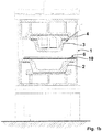
- Figure 1c shows a forming press in which the forming takes place in a first forming step by means of internal gas pressure.
- an internal pressure of, for example, 20 bar can be provided and this as a function of the wall thickness and the material, with material being able to be actively pushed into the engraving above the tool base 5 in order to have sufficient material available for a subsequent cold forming, for example.
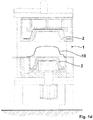
- Fig. 1d shows a purely mechanical deformation as a second deformation step with a punch 3 and an engraving 2, wherein the material of the workpiece can be freely adjusted.
- a gas supply 4 is again provided into the space above the punch 3 for calibration, with the surface of the molded component being smoothed with the mold closed under high pressure of up to approx. 1,000 bar, advantageously up to 200 bar, with sealed edge areas . There is no material replenishment in the engraving.
- Fig. 2 shows a forming press 1 with two engravings 2 for forming a hollow body blank 11.
- the hollow body blank is located in the area between the engravings or matrices, the engravings forming the negative shape for the final shape formed from the hollow body blank.
- the locking device 12 engages laterally on the hollow body blank.
- the locking device 12 comprises a cylinder 13 which seals on both sides of the hollow body blank and is also able to push material of the hollow body blank into the space between the two engravings. At least one of the cylinders 13 can have an opening 4 for supplying a gas for reshaping the hollow body blank.
Landscapes
- Engineering & Computer Science (AREA)
- Mechanical Engineering (AREA)
- Physics & Mathematics (AREA)
- Chemical & Material Sciences (AREA)
- Thermal Sciences (AREA)
- Fluid Mechanics (AREA)
- Crystallography & Structural Chemistry (AREA)
- Materials Engineering (AREA)
- Metallurgy (AREA)
- Organic Chemistry (AREA)
- Shaping Metal By Deep-Drawing, Or The Like (AREA)
Description
- Die vorliegende Erfindung betrifft einerseits ein Verfahren zum Umformen eines Blechrohlings, z. B. einer Platine als Werkstück in einem Umformwerkzeug, z. B. einer Umformpresse, wobei das Umformwerkzeug mindestens eine Gravur und vorteilhaft mindestens einen Niederhalter zur Fixierung des Werkstücks an der Gravur während der Umformung aufweist. Andererseits ist Gegenstand der Erfindung ein Verfahren zum Umformen eines Hohlkörperrohlings als Werkstück in einem Umformwerkzeug, z. B. einer Umformpresse mit insbesondere mindestens einer Zuhaltevorrichtung für den Hohlkörperrohling, wobei das Umformwerkzeug wenigstens eine Gravur zur Aufnahme des Hohlkörperrohlings während der Umformung aufweist.
- Umformverfahren sind aus dem Stand der Technik hinreichend bekannt. So ist beispielsweise aus der
WO 2015/136299 A2 bekannt, ein metallisches Werkstück zunächst auf den Bereich der Lösungsglühtemperatur aufzuheizen, um dann in einem weiteren Schritt das Werkstück auf die Umformtemperatur herabzukühlen, das Werkstück umzuformen, wobei während der Umformung das Werkstück weiterhin unkontrolliert abkühlt und das Umformmaterial unkontrolliert verfestigt, was zu einem Rückfedereffekt führt. Nach Abschluss der Umformung wird dann das Werkstück der Form entnommen. Nachteilig an diesem bekannten Verfahren ist die verhältnismäßig lange Taktzeit, die nicht optimale, zu kalte Umformtemperatur und die Rückfederung, die die Toteranzeinhaltung beeinträchtigt. Die lange Taktzeit ist bedingt durch die ungünstige Abfolge von Bearbeitungsvorgängen bis zur eigentlichen Umformung, wie nämlich insbesondere das Aufheizen auf die Lösungsglühtemperatur und das nachfolgende Abkühlen vor der Umformung, einschließlich der Zeit der Abkühlung des Werkstücks im Werkzeug wie auch die Abkühlung während des Umformvorganges. Die zu schnelle Abkühlung des Rohlings während des Umformens erlaubt insbesondere bei geringen A80-% Dehnungen des Werkstückes bei insbesondere hochfesten Legierungen und/oder geringen Wanddicken, nur geringe Umformgrade. Demzufolge sind enge Radien und scharfe Kanten nicht darstellbar, da je dünner die Wanddicke des Rohlings bzw. des Werkstücks ist, desto schneller kühlt es sich auch nach dem Einlegen in das Werkzeug ab und das bevor es vollständig umgeformt ist. - Darüber hinaus ist die sogenannte superplastische Umformung (SPF) ebenfalls Stand der Technik. Bei der superplastischen Umformung ist das Werkstück, also beispielsweise eine Platine oder ein Hohlkörper, fest in dem auf die superplastische Temperatur erwärmten Werkzeug eingespannt, das sich in der Regel in einem Ofen befindet. Das heißt, dass beispielsweise die Platine beim Schließen zwischen den zwei Werkzeughälften formschlüssig abgedichtet wird, sodass kein Material während der Umformung in die Gravur nachfließen kann. Die Folge hiervon ist, dass die Wandstärke des Werkstücks in der Gravur in Bezug auf den Ort in der Gravur undefiniert ist. Das heißt, an verschiedenen Stellen kann die Wandstärke in Abhängigkeit von den dort vorherrschenden Reibbeiwerten bzw. Temperaturen unterschiedliche, nicht vorherbestimmbare Stärken aufweisen. Insofern erfolgt die Ausbildung der Wandstärke in der Gravur mehr oder weniger zufällig.
- Als ebenfalls nachteilig bei der SPF hat sich Forderung an das Umformmaterial herausgestellt, dass es sich superplastisch verhält. Dies erhöht den Preis des Ausgangsmaterials deutlich. Ebenfalls betragen die SPF-Taktzeiten Minuten bis Tage in Abhängigkeit des Umformgrades. Insofern wird die SPF-Technologie auch generell für größere Stückzahlen nicht angewandt, da sie unwirtschaftlich ist.
- Aus der
DE 10 2012 007213 A1 ist ein Verfahren zum Umformen eines Blechrohlings gemäß dem Oberbegriff des Anspruchs 1 bekannt und aus derDE 11 2005 000491 T5 ist ein Verfahren zum Umformen eines Hohlkörperrohlings gemäß dem Oberbegriff des Anspruchs 2 bekannt. - Die der Erfindung zugrundeliegende Aufgäbe besteht darin, hier Abhilfe zu schaffen. Insbesondere soll ein Verfahren bereitgestellt werden, mit dem bei im Wesentlichen vorbestimmbarer Wandstärke des Werkstückes bei der Umformung kurze Taktzeiten verwirklicht werden können.
- Des Weiteren soll sich das Verfahren eignen zur Verformung von hochfesten Legierungen beliebiger Wanddicke und bei gewünscht hohen Umformgraden. Darüber hinaus ist Ziel des Verfahrens, Werkstücke herzustellen mit vorbestimmbarer Wandstärke und auch solche Werkstücke, die sich durch kleine Radien auszeichnen, wobei während der Umformung die Taktzeiten möglichst geringgehalten werden sollen.
- Zur Lösung der Aufgabe ist nach einer ersten Ausführungsform eines Verfahrens zum Umformen einer Platine als Werkstück in einem Umformwerkzeug, bei dem das Umformwerkzeug wenigstens eine Gravur oder Matrize und vorteilhaft mindestens einen Niederhalter zur Fixierung des Werkstückes an der Gravur während der Umformung aufweist, erfindungsgemäß vorgesehen, dass die Umformung im Lösungsglühtemperaturbereich des Materials des umzuformenden Werkstückes erfolgt, wobei das Werkzeug auf die werkstückspezifische Lösungsglühtemperatur eingestellt wird, wobei der Druck des Niederhalters zur Fixierung des Werkstücks an der Gravur so gewählt ist, dass Material des Werkstücks in die Gravur nachfließen kann und/oder wobei Material des Werkstücks aktiv in die Gravur eingeschoben wird, oder wobei die Umformung gänzlich ohne zusätzliches Werkstückmaterial in der Gravur erfolgt. Der Niederhalter kann bei bestimmten Umformvorgängen vorteilhaft sein, beispielsweise beim Tiefziehen mit einem Stempel, wobei durch den Niederhalter der Materialnachschub in die Gravur steuerbar ist.
- Ist ein Niederhalter vorgesehen, so ist die Druck- oder die Presskraft auf das Werkstück zwischen Niederhalter und Gravur maßgeblich für die Frage, ob und gegebenenfalls wieviel Material des Werkstücks in die Gravur nachfließen kann.
- Nach einer zweiten Ausführungsform ist zum Verformen eines Hohlkörperrohlings als Werkstück in einem Umformwerkzeug, insbesondere mit mindestens einer Zuhaltevorrichtung für den Hohlkörperrohling, wobei das Umformwerkzeug mindestens eine Gravur oder Matrize zur Aufnahme des Hohlkörperrohlings während der Umformung aufweist, erfindungsgemäß vorgesehen, dass die Umformung im Lösungsglühtemperaturbereich des Materials des umzuformenden Werkstückes erfolgt, wobei das Werkzeug auf die werkstückspezifische Lösungsglühtemperatur eingestellt wird, wobei durch die Zuhaltevorrichtung das Werkstück (der Hohlkörperrohling) so gehalten wird, dass Material des Werkstücks nachfließen kann, und/oder das Material des Werkstücks aktiv in die Gravur hineingeschoben wird,oder dass die Umformung auf der Basis des Materials des Hohlkörperrohlings erfolgt, das sich innerhalb der Gravur befindet.
- Der Kern der Erfindung besteht also darin, das umzuformende Werkstück, also beispielsweise den Rohling, auf die Lösungsglüh- bzw. Austenitisierungstemperatur aufzuheizen, um dann entweder nach Abschluss oder während des Lösungsglühvorganges bzw. nach Abschluss der Austenitisierung, in der ebenfalls vorteilhaft auf diese Temperatur gebrachten Gravur, die Umformung vorzunehmen. Das heißt, durch die Umformung aus der Lösungsglühtemperatur heraus ist ein spannungsfreies Umformen möglich. Denkbar wäre in diesem Zusammenhang auch, wenn das Werkstück bereits einen Lösungsglühvorgang durchlaufen bzw. austenitisiert wäre, die Umformung im dauerhaft in der Nähe der Lösungsglühtemperatur erwärmten Werkzeug im Bereich der optimalen Dehnung des Materials des Werkstücks vorzunehmen. Der Begriff "dauerhaft" soll zumindest den Zeitraum während des Lösungsglühen und der Umformung beschreiben. Vorteilhaft soll die Temperatur während des täglichen Produktionsprozesses aufrechterhalten werden, weil dann der Verschleiß insbesondere an der Gravur vermindert werden kann. Dies gegenüber einem beständigen Aufheizen und Abkühlen des Umformwerkzeugs, was zu einem erhöhten Verschleiß am Umformwerkzeug führt, denn das Abkühlen ist einem wiederkehrenden Thermoschock gleichzusetzen.
- Im Folgenden wird unter der Lösungsglühtemperatur in Bezug auf Stahl auch die Austenitisierungstemperatur verstanden. Das heißt, der Begriff der Lösungsglühtemperatur stellt sich insofern als Oberbegriff für eine spezielle Wärmebehandlung mit einer Temperatur dar, die auch die Austenitisierungstemperatur bei Stahl umfasst.
- Gegenstand des Verfahrens ist, wie bereits ausgeführt, die Erwärmung des Werkstücks auf den Lösungsglühtemperaturbereich, der spezifisch für das Material des umzuformenden Werkstückes vorgesehen ist. Hierbei wird die Temperatur vorteilhaft so ausgewählt, dass sie ein Lösungsglühen ermöglicht, aber die Materialstruktur nicht schädigt bzw. bei beispielsweise martensitischen Stählen, die Temperatur für das Austenitisieren bzw. Lösungsglühen oberhalb der AC3-Linie, das heißt ungefähr bei 950°C liegt.
- In Abhängigkeit von dem umzuformenden Material kann der Lösungsglühvorgang des Werkstückes vor dem Beginn der Umformung abgeschlossen sein, er kann während des Lösungsglühvorganges beginnen, und auch noch während des Umformvorganges abgeschlossen sein. Welche Variante gewählt wird, hängt, wie bereits ausgeführt, vom Material ab, und von dem Ziel der Verwirklichung einer möglichst geringen Taktzeit.
- Nach einem weiteren Merkmal der Erfindung ist vorgesehen, dass das Werkstück vor Einbringen in das im Wesentlichen dauerhaft erwärmte Werkzeug auf die für das Material des Werkstückes auf den Lösungsglühtemperaturbereich bzw. Austenitisierungstemperaturbereich erwärmt wird. Auch dies dient der Verminderung der Taktzeit. Gleiches gilt für die Temperatur des im Wesentlichen dauerhaft erwärmten Werkzeuges.
- Als besonders vorteilhaft hat sich herausgestellt, wenn das Werkstück nach Abschluss der Umformung und/oder nach Abschluss des Lösungsglühvorganges aus dem Umformwerkzeug entnommen und einem Härtevorgang zugeführt wird. Üblicherweise ist es so, dass vor der Härtung das Werkstück auf Lösungsglühtemperatur gebracht Wird, in Bezug auf Stahl spricht man von Austenitisierung. Wenn insofern bereits die Umformung vorteilhaft bei der Lösungsglühtemperatur erfolgt, dann kann, ohne ein erneutes Aufheizen des Werkstücks das Werkstück nach der Umformung unmittelbar optimal gehärtet werden, sei es durch entsprechende Abkühlung oder Umformung bei gegenüber der Lösungsglühtemperatur niedrigeren Temperaturen.
- Als weiterhin vorteilhaft hat sich herausgestellt, wenn in Abhängigkeit der Bildung einer an einem vorgegebenen Ort in der Gravur gewünschten Materialreserve am Werkstück ein entsprechendes Temperaturprofil in der Gravur durch eine Temperiereinrichtung einstellbar ist. Das heißt, dass beispielsweise an Stellen, an denen eine geringere Wandstärke gewünscht wird, die Temperatur in der Gravur höher ist als an anderen Stellen der Gravur. In diesem Zusammenhang kann ebenfalls eine Differenzierung in der Wandstärke dadurch vorgenommen werden, dass in Abhängigkeit von einer an einem vorgegebenen Ort in der Gravur gewünschten Materialreserve am Werkstück auf die Gravur ein entsprechendes Rauheitsprofil aufgebracht wird. Das heißt, dass durch einen geänderten Reibbeiwert an bestimmten Stellen in der Gravur das Fließverhalten des Materials beeinflussbar ist, um so Stellen unterschiedlicher Materialstärke zu schaffen.
- Als besonders vorteilhaft hat sich eine Kombination der Aufbringung eines bestimmten Rauheitsprofils und eines Temperaturprofils herausgestellt. Es hat sich gezeigt, dass insbesondere durch eine solche Kombination die Wandstärken an bestimmten Stellen in der Gravur sehr fein einstellbar sind.
- Nach einem weiteren Merkmal der Erfindung erfolgt die Umformung des Werkstückes in der Gravur unter Gasdruck und/oder mechanisch mit einem Stempel. Vorteilhaft ist bei Gasumformung vorgesehen, wenn zwischen Gravur oder Niederhalter und Platine eine Dichtung angeordnet ist, um den Gasaustritt zu verhindern oder zumindest zu vermindern. Es hat sich in diesem Zusammenhang weiterhin als vorteilhaft herausgestellt, dass nach Abschluss des Umformvorgangs zur Kalibrierung des Werkstücks in der Gravur das Werkstück durch die Gravur oder den Niederhalter derart erfasst wird, dass im Wesentlichen kein Werkstückmaterial in die Gravur nachfließt. Diese Maßnahme dient der Faltenglättung und findet insbesondere oberhalb von 60 bar in Abhängigkeit von der Radiusgröße, des umzuformenden Materials des Werkstückes und der Wandstärke des Werkstücks statt. Es kann ebenfalls optional vorgesehen sein, dass auch mehrere solche Umformwerkzeuge hintereinander angeordnet sein können, um ähnlich der Kaltumformung, eine optimale Umformung bei optimalen Taktzeiten zu ermöglichen. Unter optimaler Umformung versteht man eine Umformung des Werkstücks in mehreren Schritten, die in einem einzigen Umformvorgang nicht darstellbar wäre. Gegenüber z. B. der superplastischen Umformung könnte hier die gesamte Taktzeit, die insgesamt zur Umformung notwendig war, verkürzt werden, weil die Umformung in mehreren Schritten notwendig wäre, somit insgesamt im Bereich der Lösungsglühtemperatur stattfindet.
- Mit Hilfe des erfindungsgemäßen Verfahrens, das heißt insbesondere mit Hilfe eines Verfahrens, bei dem die Umformung im Bereich der Lösungsglühtemperatur stattfindet und bei dem, wie bereits zu eingangs erläutert, das Material des Werkstücks aus dem Bereich des Niederhalters in die Gravur nachfließen kann, können Umformzeiten von kleiner einer Minute verwirklicht werden, insbesondere von ≤ 20 Sekunden bei Umformung unter Gasdruck und ≤ 10 Sekunden bei mechanischer Umformung. Bei einer optimalen Kombination von hintereinander angeordneten Werkzeugen können komplexe Bauteile aus höchst festen Werkstoffen beliebiger Wanddicke mit sehr kleinen Radien oder scharfen Ecken bzw. sehr hohen Umformgraden von mehr als 200% in einer sehr kurzen Taktzeit umgeformt werden.
- Anhand der Zeichnungen wird die Erfindung nachstehend beispielhaft näher erläutert. So zeigen die
- Fig. 1a und Fig. 1b
- eine Umformpresse zum Umformen einer metallischen Platine mit mechanischer und ergänzend mit Gasdruck-Umformung;
- Fig. 1c bis 1d
- zeigen einen Umformvorgang eines Blechrohlings in drei Schritten in unterschiedlichen Werkzeugen;
- Fig. 2
- zeigt eine Umformungspresse für die Umformung eines Hohlkörperrohlings.
- Im Einzelnen ist aus den
Figuren 1a - 1d bei der Umformpresse 1 die Gravur mit 2 und der Stempel mit 3 bezeichnet. Eine Gaszuführung ist schematisch mit 4 angedeutet. Die Platine oder der Blechrohling hat das Bezugszeichen 10. - In diesem Zusammenhang ergibt sich aus
Fig. 1a eine Gravur sowie ein Stempel für eine rein mechanische Umformung der Platine 10. Ein Niederhalter für die Platine hat das Bezugszeichen 6. -
Fig. 1b zeigt eine mechanische Umformung in Kombination mit einer Gasdruckkalibrierung, wobei hierbei eine Gaszuführung 4 in den Bereich oberhalb der Platine, also in den Bereich des Stempels 3 vorgesehen ist. Auch hier ist ein Niederhalter 6 vorgesehen. Der Niederhalter bringt eine Presskraft auf die Platine bzw. den Blechrohling in Verbindung mit der Gravur 2. -
Fig. 1c zeigt eine Umformpresse, bei der in einem ersten Umformschritt durch Gasinnendruck die Umformung erfolgt. Hierbei kann ein Innendruck von beispielsweise 20 bar vorgesehen sein und dies in Abhängigkeit von der Wandstärke und dem Material, wobei über dem Werkzeuguntergestell 5 aktiv Material in die Gravur nachgeschoben werden kann, um bei beispielsweise einer nachfolgenden Kaltumformung ausreichend Material zur Verfügung zu haben. -
Fig. 1d zeigt eine rein mechanische Umformung als zweiten Umformschritt mit einem Stempel 3 und einer Gravur 2, wobei das Material des Werkstücks frei nachgeführt werden kann. Man spricht hier auch von freiem Materialeinzug. - Bei
Fig. 1e ist bei dem dritten Umformschritt zur Kalibrierung wiederum eine Gaszufuhr 4 in den Raum oberhalb des Stempels 3 vorgesehen, wobei bei geschlossenem Werkzeug unter hohem Druck von bis zu ca. 1.000 bar, vorteilhaft bis 200 bar, bei abgedichteten Randbereichen die Oberfläche des geformten Bauteils geglättet wird. Hierbei erfolgt kein Materialnachschub in die Gravur. -
Fig. 2 zeigt eine Umformpresse 1 mit zwei Gravuren 2 zum Umformen eines Hohlkörperrohlings 11. Der Hohlkörperrohling lagert im Bereich zwischen den Gravuren oder Matrizen, wobei die Gravuren die Negativform für die aus dem Hohlkörperrohling gebildete Endform bilden. An dem Hohlkörperrohling greifen seitlich die Zuhaltevorrichtung 12 an. Die Zuhaltevorrichtung 12 umfasst jeweils einen zu beiden Seiten des Hohlkörperrohlings abdichtenden Zylinder 13, der auch in der Lage ist, Material des Hohlkörperrohlings in den Raum zwischen den beiden Gravuren nachzuschieben. Zumindest einer der Zylinder 13 kann eine Öffnung 4 zur Zuführung von einem Gas zur Umformung des Hohlkörperrohlings aufweisen. -
- 1
- Umformpresse
- 2
- Gravur
- 3
- Stempel
- 4
- Gaszufuhr
- 5
- Werkzeuguntergestell
- 6
- Niederhalter
- 10
- Blechrohling
- 11
- Hohlkörperrohling
- 12
- Zuhaltevorrichtung
- 13
- Zylinder der Zuhaltevorrichtung
Claims (16)
- Verfahren zum Umformen eines Blechrohlings (10), z. B. einer Platine als Werkstück in einem Umformwerkzeug, z. B. einer Umformpresse (1), wobei das Umformwerkzeug mindestens eine Gravur (2) und vorteilhaft mindestens einen Niederhalter (6) zur Fixierung des Werkstücks an der Gravur (2) während der Umformung aufweist, dadurch gekennzeichnet,
dass die Umformung im Lösungsglühtemperaturbereich des Materials des umzuformenden Werkstücks erfolgt,
wobei das Werkzeug auf die werkstückspezifische Lösungsglühtemperatur eingestellt wird,
wobei der Druck des Niederhalters (6) oder des Randbereichs der Gravur (2) auf das Werkstück so gewählt ist, dass Material des Werkstücks aus dem Bereich des Niederhalters (6) oder des Randbereichs der Gravur (2) in die Gravur (2) nachfließen kann und/oder
wobei Material des Werkstücks aktiv in die Gravur (2) hineingeschoben wird, oder
wobei die Umformung gänzlich ohne zusätzliches Werkstückmaterial in der Gravur (2) erfolgt. - Verfahren zum Umformen eines Hohlkörperrohlings als Werkstück in einem Umformwerkzeug, z. B. einer Umformpresse (1) mit mindestens einer Zuhaltevorrichtung (12) für den Hohlkörperrohling (11), wobei das Umformwerkzeug mindestens eine Gravur (2) zur Aufnahme des Hohlkörperrohlings (11) während der Umformung aufweist,
dadurch gekennzeichnet,
dass die Umformung im Lösungsglühtemperaturbereich des Materials des zu formenden Werkstücks erfolgt, wobei das Werkzeug auf die werkstückspezifische Lösungsglühtemperatur eingestellt wird , wobei durch die Zuhaltevorrichtung das Werkstück so gehalten wird, dass Material des Werkstücks in die Gravur nachfließen kann,- und/oder dass Material des Werkstücks aktiv in die Gravur (2) hineingeschoben wird,- oder dass die Umformung auf der Basis des Materials des Hohlkörperrohlings erfolgt, der sich innerhalb der Gravur (2) befindet. - Verfahren nach Anspruch 1 oder 2,
dadurch gekennzeichnet,
dass der Lösungsglühvorgang des Werkstücks vor dem Beginn der Umformung abgeschlossen ist. - Verfahren nach einem der voranstehenden Ansprüche,
dadurch gekennzeichnet,
dass während des Lösungsglühvorganges der Umformvorgang des Werkstückes beginnt. - Verfahren nach Anspruch 4,
dadurch gekennzeichnet,
dass der Lösungsglühvorgang während des Umformvorganges abgeschlossen wird. - Verfahren nach einem der voranstehenden Ansprüche,
dadurch gekennzeichnet,
dass das Werkstück vor Einbringen in das Umformwerkzeug auf die Lösungsglühtemperatur erwärmt wird. - Verfahren nach einem der voranstehenden Ansprüche,
dadurch gekennzeichnet,
dass das Werkstück nach Abschluss der Umformung und/oder nach Abschluss des Lösungsglühvorganges aus dem Werkzeug entnommen und einem Härtevorgang zugeführt wird. - Verfahren nach Anspruch 7,
dadurch gekennzeichnet,
dass der Härtevorgang einen Abkühlvorgang und/oder einen Umformvorgang in einem weiteren Werkzeug umfasst. - Verfahren nach einem der voranstehenden Ansprüche 1 bis 8,
dadurch gekennzeichnet,
dass in Abhängigkeit der Bildung einer an einem vorgegebenen Ort in der Gravur (2) gewünschten Materialreserve am Werkstück, ein entsprechendes Temperaturprofil in der Gravur (2) durch eine Temperiereinrichtung einstellbar ist. - Verfahren nach einem der voranstehenden Ansprüche 1 bis 8,
dadurch gekennzeichnet,
dass in Abhängigkeit der Bildung einer an einem vorgegebenen Ort in der Gravur (2) gewünschten Materialreserve am Werkstück, auf die Gravur (2) ein entsprechendes Rauheitsprofil aufgebracht ist. - Verfahren nach Anspruch 9 oder 10,
dadurch gekennzeichnet,
dass im Bereich der Anordnung eines Rauheitsprofils in der Gravur (2) durch die Temperiereinrichtung ein Temperaturprofil aufbringbar ist. - Verfahren nach einem der voranstehenden Ansprüche,
dadurch gekennzeichnet,
dass die Umformung unter Gasdruck und/oder mechanisch erfolgt. - Verfahren nach einem der voranstehenden Ansprüche 1 und 3 bis 12,
dadurch gekennzeichnet,
dass bei Gasumformung zur Minimierung des Austritts von Gas zwischen Werkstück und Gravur (2) oder Werkstück und Niederhalter (6) oder zwischen Niederhalter (6) und Werkstück ein Dichtungselement vorgesehen ist. - Verfahren nach einem der voranstehenden Ansprüche 1 und 3 bis 13,
dadurch gekennzeichnet,
dass im Anschluss an den Umformvorgang, zur Kalibrierung des Werkstücks in der Gravur (2) mittels hohem Gasdruck bis 1000 bar, das Werkstück durch den Niederhalter (6) oder die Gravur (2) derart erfasst wird, dass kein Werkstückmaterial in die Gravur (2) nachfließt. - Verfahren nach einem der voranstehenden Ansprüche,
dadurch gekennzeichnet,
dass die Taktzeit zwischen der Beschickung des Umformwerkzeuges mit dem umzuformenden Werkstück und der Entnahme des umgeformten Werkstückes aus dem Umformwerkzeug ≤ eine Minute, bei Umformung unter Gasdruck ≤ 20 Sekunden, und bei mechanischer Umformung ≤ 10 Sekunden beträgt. - Verfahren nach einem der voranstehenden Ansprüche,
dadurch gekennzeichnet,
dass das Werkstück auf die werkstückspezifische Lösungsglühtemperatur eingestellt wird.
Applications Claiming Priority (1)
| Application Number | Priority Date | Filing Date | Title |
|---|---|---|---|
| DE102017127158.9A DE102017127158A1 (de) | 2017-11-17 | 2017-11-17 | Verfahren zum Umformen eines Blechrohlings, z. B. einer Platine oder eines Hohlkörperrohlings als Werkstück in einem Umformwerkzeug |
Publications (2)
| Publication Number | Publication Date |
|---|---|
| EP3485992A1 EP3485992A1 (de) | 2019-05-22 |
| EP3485992B1 true EP3485992B1 (de) | 2020-10-14 |
Family
ID=63914822
Family Applications (1)
| Application Number | Title | Priority Date | Filing Date |
|---|---|---|---|
| EP18201134.6A Active EP3485992B1 (de) | 2017-11-17 | 2018-10-18 | Verfahren zum umformen eines blechrohlings, z.b. einer platine oder eines hohlkörperrohlings als werkstück in einem umformwerkzeug |
Country Status (3)
| Country | Link |
|---|---|
| US (2) | US12064800B2 (de) |
| EP (1) | EP3485992B1 (de) |
| DE (1) | DE102017127158A1 (de) |
Cited By (1)
| Publication number | Priority date | Publication date | Assignee | Title |
|---|---|---|---|---|
| WO2023104239A1 (de) | 2021-12-10 | 2023-06-15 | Schaeffler Technologies AG & Co. KG | Bipolarplatte und verfahren zum prägen einer kanalstruktur |
Families Citing this family (1)
| Publication number | Priority date | Publication date | Assignee | Title |
|---|---|---|---|---|
| DE102021113628A1 (de) | 2021-05-26 | 2022-12-01 | Deutsches Zentrum für Luft- und Raumfahrt e.V. | Verfahren und Vorrichtung zur Herstellung eines Hohlkörpers mit räumlich variierender Wanddicke |
Family Cites Families (15)
| Publication number | Priority date | Publication date | Assignee | Title |
|---|---|---|---|---|
| SE435527B (sv) * | 1973-11-06 | 1984-10-01 | Plannja Ab | Forfarande for framstellning av en detalj av herdat stal |
| US6033499A (en) * | 1998-10-09 | 2000-03-07 | General Motors Corporation | Process for stretch forming age-hardened aluminum alloy sheets |
| FR2792001B1 (fr) | 1999-04-12 | 2001-05-18 | Pechiney Rhenalu | Procede de fabrication de pieces de forme en alliage d'aluminium type 2024 |
| WO2005084845A1 (en) * | 2004-03-02 | 2005-09-15 | Magtech-Magnesium Technologies Ltd. | An article made of a magnesium alloy tube |
| US7159437B2 (en) * | 2004-10-07 | 2007-01-09 | General Motors Corporation | Heated die for hot forming |
| DE102009003508B4 (de) * | 2009-02-19 | 2013-01-24 | Thyssenkrupp Steel Europe Ag | Verfahren zur Herstellung eines pressgehärteten Metallbauteils |
| DE102009010490A1 (de) * | 2009-02-25 | 2010-09-02 | Amborn, Peter, Dr. Ing. | Verfahren zur Herstellung eines Hohlkörpers durch Beaufschlagung eines solchen in einer Kavität einliegenden Hohlkörperrohlings mit Innendruck unter erhöhter Temperatur |
| DE102009050533A1 (de) * | 2009-10-23 | 2011-04-28 | Thyssenkrupp Sofedit S.A.S | Verfahren und Warmumformanlage zur Herstellung eines gehärteten, warm umgeformten Werkstücks |
| TW201129431A (en) * | 2010-02-26 | 2011-09-01 | Fu-Tang Li | Metal molding method and products formed therefrom |
| DE102012007213A1 (de) * | 2012-04-11 | 2012-11-29 | Daimler Ag | Verfahren zur Herstellung eines Aluminiumformteils |
| DE102014003350A1 (de) * | 2014-03-07 | 2015-09-10 | Fraunhofer-Gesellschaft zur Förderung der angewandten Forschung e.V. | Verfahren und Vorrichtung zum Umformen eines Werkstücks |
| GB2527486A (en) | 2014-03-14 | 2015-12-30 | Imp Innovations Ltd | A method of forming complex parts from sheet metal alloy |
| DE102016100589A1 (de) * | 2016-01-14 | 2017-07-20 | Voestalpine Metal Forming Gmbh | Verfahren und Vorrichtung zum Warmformen von Stahlblechen |
| US10857858B2 (en) * | 2016-03-23 | 2020-12-08 | Nippon Steel Corporation | Door inner panel and method for manufacturing door inner panel |
| EP3481564A1 (de) * | 2016-07-11 | 2019-05-15 | Sapa AS | Heissmetallgasgeformte dachreling und verfahren zur herstellung davon |
-
2017
- 2017-11-17 DE DE102017127158.9A patent/DE102017127158A1/de not_active Withdrawn
-
2018
- 2018-10-18 EP EP18201134.6A patent/EP3485992B1/de active Active
- 2018-11-19 US US16/195,396 patent/US12064800B2/en active Active
-
2024
- 2024-07-23 US US18/780,777 patent/US20250018453A1/en active Pending
Non-Patent Citations (1)
| Title |
|---|
| None * |
Cited By (2)
| Publication number | Priority date | Publication date | Assignee | Title |
|---|---|---|---|---|
| WO2023104239A1 (de) | 2021-12-10 | 2023-06-15 | Schaeffler Technologies AG & Co. KG | Bipolarplatte und verfahren zum prägen einer kanalstruktur |
| DE102021132658A1 (de) | 2021-12-10 | 2023-06-15 | Schaeffler Technologies AG & Co. KG | Bipolarplatte und Verfahren zum Prägen einer Kanalstruktur |
Also Published As
| Publication number | Publication date |
|---|---|
| DE102017127158A1 (de) | 2019-05-23 |
| US20190151922A1 (en) | 2019-05-23 |
| US20250018453A1 (en) | 2025-01-16 |
| EP3485992A1 (de) | 2019-05-22 |
| US12064800B2 (en) | 2024-08-20 |
Similar Documents
| Publication | Publication Date | Title |
|---|---|---|
| DE102008047971B3 (de) | Verfahren und Vorrichtung zum Presshärten eines metallischen Formbauteils | |
| EP2324938B1 (de) | Verfahren und Warmumformanlage zur Herstellung eines gehärteten, warm umgeformten Werkstücks | |
| EP1786936B1 (de) | Verfahren zum presshärten von bauteilen aus stahlblech | |
| DE102013103751B4 (de) | Verfahren zur Herstellung von hochmaßhaltigen Halbschalen und Vorrichtung zur Herstellung einer Halbschale | |
| DE102014222476B4 (de) | Wärmebehandlungsvorrichtung zum Heißprägen und Ausformungsverfahren unter Verwendung dergleichen | |
| DE102009005921A1 (de) | Verfahren und Vorrichtung zum superplastischen Umformen | |
| DE102011117066B4 (de) | Vorrichtung zur Herstellung eines warmumgeformten und pressgehärteten Kraftfahrzeugkarosseriebauteils sowie Verfahren zur Herstellung | |
| WO2010020212A1 (de) | Verfahren zum formhärten mit zwischenkühlung | |
| DE102009060388A1 (de) | Mehrstufiges direktes Formhärten | |
| US20250018453A1 (en) | Method for forming a sheet blank as a workpiece in a forming tool | |
| DE60306215T2 (de) | Verfahren und Vorrichtung zum superplastischen Verformen | |
| WO2016071042A1 (de) | Umformpresse und verfahren zum umformen eines flächenförmigen rohlings aus metall mit zwei aufeinander zu verfahrbaren gestellteilen | |
| EP1462192A1 (de) | Verfahren zur Umformung einer Platine aus einem Vergütungsstahl und Vorrichtung zur Durchführung des Verfahrens | |
| DE112009000645T5 (de) | Warmumformprozess für Metalllegierungsbleche | |
| DE102006015666B4 (de) | Verfahren zur Herstellung eines metallischen Formbauteils durch Warmumformen mit simultaner Beschneideoperation | |
| DE102007014948A1 (de) | Verfahren und Vorrichtung zur Warmumformung von Blechen aus titanbasierten Legierungen | |
| DE102014213196A1 (de) | Formwerkzeug zur Herstellung von warmumgeformten Bauteilen | |
| WO2019048025A1 (de) | Verfahren zur herstellung eines bauteils und werkzeug dafür | |
| EP3212346B1 (de) | Formwerkzeug zur herstellung von warmumgeformten bauteilen | |
| EP3253509B1 (de) | Verfahren und vorrichtung zum auskragen eines werkstücks | |
| DE877617C (de) | Verfahren und Vorrichtung zum Biegen und Abkanten von Blechen und Platten | |
| DE102006046305B4 (de) | Vorrichtung zum mindestens partiellen Umformen von Blech über die bekannten Formgebungsgrenzen hinaus | |
| DE102008043401B4 (de) | Verfahren und Vorrichtung zur Herstellung von Blechbauteilen mittels Warmumformung sowie dadurch hergestellte Blechbauteile | |
| DE102007002678A1 (de) | Verfahren und Vorrichtung zum Herstellen eines warmumgeformten Blechbauteils | |
| WO2005105336A1 (de) | Verfahren und vorrichtung zum blechformen und härten |
Legal Events
| Date | Code | Title | Description |
|---|---|---|---|
| PUAI | Public reference made under article 153(3) epc to a published international application that has entered the european phase |
Free format text: ORIGINAL CODE: 0009012 |
|
| STAA | Information on the status of an ep patent application or granted ep patent |
Free format text: STATUS: THE APPLICATION HAS BEEN PUBLISHED |
|
| STAA | Information on the status of an ep patent application or granted ep patent |
Free format text: STATUS: REQUEST FOR EXAMINATION WAS MADE |
|
| AK | Designated contracting states |
Kind code of ref document: A1 Designated state(s): AL AT BE BG CH CY CZ DE DK EE ES FI FR GB GR HR HU IE IS IT LI LT LU LV MC MK MT NL NO PL PT RO RS SE SI SK SM TR |
|
| AX | Request for extension of the european patent |
Extension state: BA ME |
|
| 17P | Request for examination filed |
Effective date: 20190507 |
|
| RBV | Designated contracting states (corrected) |
Designated state(s): AL AT BE BG CH CY CZ DE DK EE ES FI FR GB GR HR HU IE IS IT LI LT LU LV MC MK MT NL NO PL PT RO RS SE SI SK SM TR |
|
| GRAP | Despatch of communication of intention to grant a patent |
Free format text: ORIGINAL CODE: EPIDOSNIGR1 |
|
| STAA | Information on the status of an ep patent application or granted ep patent |
Free format text: STATUS: GRANT OF PATENT IS INTENDED |
|
| INTG | Intention to grant announced |
Effective date: 20200228 |
|
| GRAJ | Information related to disapproval of communication of intention to grant by the applicant or resumption of examination proceedings by the epo deleted |
Free format text: ORIGINAL CODE: EPIDOSDIGR1 |
|
| STAA | Information on the status of an ep patent application or granted ep patent |
Free format text: STATUS: REQUEST FOR EXAMINATION WAS MADE |
|
| INTC | Intention to grant announced (deleted) | ||
| GRAS | Grant fee paid |
Free format text: ORIGINAL CODE: EPIDOSNIGR3 |
|
| STAA | Information on the status of an ep patent application or granted ep patent |
Free format text: STATUS: GRANT OF PATENT IS INTENDED |
|
| GRAP | Despatch of communication of intention to grant a patent |
Free format text: ORIGINAL CODE: EPIDOSNIGR1 |
|
| GRAA | (expected) grant |
Free format text: ORIGINAL CODE: 0009210 |
|
| STAA | Information on the status of an ep patent application or granted ep patent |
Free format text: STATUS: THE PATENT HAS BEEN GRANTED |
|
| INTG | Intention to grant announced |
Effective date: 20200818 |
|
| AK | Designated contracting states |
Kind code of ref document: B1 Designated state(s): AL AT BE BG CH CY CZ DE DK EE ES FI FR GB GR HR HU IE IS IT LI LT LU LV MC MK MT NL NO PL PT RO RS SE SI SK SM TR |
|
| REG | Reference to a national code |
Ref country code: GB Ref legal event code: FG4D Free format text: NOT ENGLISH |
|
| REG | Reference to a national code |
Ref country code: AT Ref legal event code: REF Ref document number: 1323072 Country of ref document: AT Kind code of ref document: T Effective date: 20201015 Ref country code: CH Ref legal event code: EP |
|
| REG | Reference to a national code |
Ref country code: DE Ref legal event code: R096 Ref document number: 502018002730 Country of ref document: DE |
|
| REG | Reference to a national code |
Ref country code: IE Ref legal event code: FG4D Free format text: LANGUAGE OF EP DOCUMENT: GERMAN |
|
| REG | Reference to a national code |
Ref country code: NL Ref legal event code: MP Effective date: 20201014 |
|
| PG25 | Lapsed in a contracting state [announced via postgrant information from national office to epo] |
Ref country code: PT Free format text: LAPSE BECAUSE OF FAILURE TO SUBMIT A TRANSLATION OF THE DESCRIPTION OR TO PAY THE FEE WITHIN THE PRESCRIBED TIME-LIMIT Effective date: 20210215 Ref country code: RS Free format text: LAPSE BECAUSE OF FAILURE TO SUBMIT A TRANSLATION OF THE DESCRIPTION OR TO PAY THE FEE WITHIN THE PRESCRIBED TIME-LIMIT Effective date: 20201014 Ref country code: FI Free format text: LAPSE BECAUSE OF FAILURE TO SUBMIT A TRANSLATION OF THE DESCRIPTION OR TO PAY THE FEE WITHIN THE PRESCRIBED TIME-LIMIT Effective date: 20201014 Ref country code: GR Free format text: LAPSE BECAUSE OF FAILURE TO SUBMIT A TRANSLATION OF THE DESCRIPTION OR TO PAY THE FEE WITHIN THE PRESCRIBED TIME-LIMIT Effective date: 20210115 Ref country code: NO Free format text: LAPSE BECAUSE OF FAILURE TO SUBMIT A TRANSLATION OF THE DESCRIPTION OR TO PAY THE FEE WITHIN THE PRESCRIBED TIME-LIMIT Effective date: 20210114 |
|
| REG | Reference to a national code |
Ref country code: LT Ref legal event code: MG4D |
|
| PG25 | Lapsed in a contracting state [announced via postgrant information from national office to epo] |
Ref country code: ES Free format text: LAPSE BECAUSE OF FAILURE TO SUBMIT A TRANSLATION OF THE DESCRIPTION OR TO PAY THE FEE WITHIN THE PRESCRIBED TIME-LIMIT Effective date: 20201014 Ref country code: SE Free format text: LAPSE BECAUSE OF FAILURE TO SUBMIT A TRANSLATION OF THE DESCRIPTION OR TO PAY THE FEE WITHIN THE PRESCRIBED TIME-LIMIT Effective date: 20201014 Ref country code: LV Free format text: LAPSE BECAUSE OF FAILURE TO SUBMIT A TRANSLATION OF THE DESCRIPTION OR TO PAY THE FEE WITHIN THE PRESCRIBED TIME-LIMIT Effective date: 20201014 Ref country code: IS Free format text: LAPSE BECAUSE OF FAILURE TO SUBMIT A TRANSLATION OF THE DESCRIPTION OR TO PAY THE FEE WITHIN THE PRESCRIBED TIME-LIMIT Effective date: 20210214 Ref country code: PL Free format text: LAPSE BECAUSE OF FAILURE TO SUBMIT A TRANSLATION OF THE DESCRIPTION OR TO PAY THE FEE WITHIN THE PRESCRIBED TIME-LIMIT Effective date: 20201014 Ref country code: BG Free format text: LAPSE BECAUSE OF FAILURE TO SUBMIT A TRANSLATION OF THE DESCRIPTION OR TO PAY THE FEE WITHIN THE PRESCRIBED TIME-LIMIT Effective date: 20210114 |
|
| PG25 | Lapsed in a contracting state [announced via postgrant information from national office to epo] |
Ref country code: LU Free format text: LAPSE BECAUSE OF NON-PAYMENT OF DUE FEES Effective date: 20201018 Ref country code: HR Free format text: LAPSE BECAUSE OF FAILURE TO SUBMIT A TRANSLATION OF THE DESCRIPTION OR TO PAY THE FEE WITHIN THE PRESCRIBED TIME-LIMIT Effective date: 20201014 Ref country code: NL Free format text: LAPSE BECAUSE OF FAILURE TO SUBMIT A TRANSLATION OF THE DESCRIPTION OR TO PAY THE FEE WITHIN THE PRESCRIBED TIME-LIMIT Effective date: 20201014 |
|
| REG | Reference to a national code |
Ref country code: DE Ref legal event code: R097 Ref document number: 502018002730 Country of ref document: DE Ref country code: BE Ref legal event code: MM Effective date: 20201031 |
|
| PG25 | Lapsed in a contracting state [announced via postgrant information from national office to epo] |
Ref country code: MC Free format text: LAPSE BECAUSE OF FAILURE TO SUBMIT A TRANSLATION OF THE DESCRIPTION OR TO PAY THE FEE WITHIN THE PRESCRIBED TIME-LIMIT Effective date: 20201014 Ref country code: LT Free format text: LAPSE BECAUSE OF FAILURE TO SUBMIT A TRANSLATION OF THE DESCRIPTION OR TO PAY THE FEE WITHIN THE PRESCRIBED TIME-LIMIT Effective date: 20201014 Ref country code: RO Free format text: LAPSE BECAUSE OF FAILURE TO SUBMIT A TRANSLATION OF THE DESCRIPTION OR TO PAY THE FEE WITHIN THE PRESCRIBED TIME-LIMIT Effective date: 20201014 Ref country code: EE Free format text: LAPSE BECAUSE OF FAILURE TO SUBMIT A TRANSLATION OF THE DESCRIPTION OR TO PAY THE FEE WITHIN THE PRESCRIBED TIME-LIMIT Effective date: 20201014 Ref country code: CZ Free format text: LAPSE BECAUSE OF FAILURE TO SUBMIT A TRANSLATION OF THE DESCRIPTION OR TO PAY THE FEE WITHIN THE PRESCRIBED TIME-LIMIT Effective date: 20201014 Ref country code: SK Free format text: LAPSE BECAUSE OF FAILURE TO SUBMIT A TRANSLATION OF THE DESCRIPTION OR TO PAY THE FEE WITHIN THE PRESCRIBED TIME-LIMIT Effective date: 20201014 Ref country code: SM Free format text: LAPSE BECAUSE OF FAILURE TO SUBMIT A TRANSLATION OF THE DESCRIPTION OR TO PAY THE FEE WITHIN THE PRESCRIBED TIME-LIMIT Effective date: 20201014 |
|
| PLBE | No opposition filed within time limit |
Free format text: ORIGINAL CODE: 0009261 |
|
| STAA | Information on the status of an ep patent application or granted ep patent |
Free format text: STATUS: NO OPPOSITION FILED WITHIN TIME LIMIT |
|
| PG25 | Lapsed in a contracting state [announced via postgrant information from national office to epo] |
Ref country code: BE Free format text: LAPSE BECAUSE OF NON-PAYMENT OF DUE FEES Effective date: 20201031 Ref country code: DK Free format text: LAPSE BECAUSE OF FAILURE TO SUBMIT A TRANSLATION OF THE DESCRIPTION OR TO PAY THE FEE WITHIN THE PRESCRIBED TIME-LIMIT Effective date: 20201014 |
|
| 26N | No opposition filed |
Effective date: 20210715 |
|
| PG25 | Lapsed in a contracting state [announced via postgrant information from national office to epo] |
Ref country code: AL Free format text: LAPSE BECAUSE OF FAILURE TO SUBMIT A TRANSLATION OF THE DESCRIPTION OR TO PAY THE FEE WITHIN THE PRESCRIBED TIME-LIMIT Effective date: 20201014 Ref country code: IE Free format text: LAPSE BECAUSE OF NON-PAYMENT OF DUE FEES Effective date: 20201018 Ref country code: FR Free format text: LAPSE BECAUSE OF NON-PAYMENT OF DUE FEES Effective date: 20201214 Ref country code: IT Free format text: LAPSE BECAUSE OF FAILURE TO SUBMIT A TRANSLATION OF THE DESCRIPTION OR TO PAY THE FEE WITHIN THE PRESCRIBED TIME-LIMIT Effective date: 20201014 |
|
| PG25 | Lapsed in a contracting state [announced via postgrant information from national office to epo] |
Ref country code: SI Free format text: LAPSE BECAUSE OF FAILURE TO SUBMIT A TRANSLATION OF THE DESCRIPTION OR TO PAY THE FEE WITHIN THE PRESCRIBED TIME-LIMIT Effective date: 20201014 |
|
| REG | Reference to a national code |
Ref country code: CH Ref legal event code: PL |
|
| PG25 | Lapsed in a contracting state [announced via postgrant information from national office to epo] |
Ref country code: IS Free format text: LAPSE BECAUSE OF FAILURE TO SUBMIT A TRANSLATION OF THE DESCRIPTION OR TO PAY THE FEE WITHIN THE PRESCRIBED TIME-LIMIT Effective date: 20210214 Ref country code: TR Free format text: LAPSE BECAUSE OF FAILURE TO SUBMIT A TRANSLATION OF THE DESCRIPTION OR TO PAY THE FEE WITHIN THE PRESCRIBED TIME-LIMIT Effective date: 20201014 Ref country code: MT Free format text: LAPSE BECAUSE OF FAILURE TO SUBMIT A TRANSLATION OF THE DESCRIPTION OR TO PAY THE FEE WITHIN THE PRESCRIBED TIME-LIMIT Effective date: 20201014 Ref country code: CY Free format text: LAPSE BECAUSE OF FAILURE TO SUBMIT A TRANSLATION OF THE DESCRIPTION OR TO PAY THE FEE WITHIN THE PRESCRIBED TIME-LIMIT Effective date: 20201014 |
|
| PG25 | Lapsed in a contracting state [announced via postgrant information from national office to epo] |
Ref country code: MK Free format text: LAPSE BECAUSE OF FAILURE TO SUBMIT A TRANSLATION OF THE DESCRIPTION OR TO PAY THE FEE WITHIN THE PRESCRIBED TIME-LIMIT Effective date: 20201014 |
|
| PG25 | Lapsed in a contracting state [announced via postgrant information from national office to epo] |
Ref country code: LI Free format text: LAPSE BECAUSE OF NON-PAYMENT OF DUE FEES Effective date: 20211031 Ref country code: CH Free format text: LAPSE BECAUSE OF NON-PAYMENT OF DUE FEES Effective date: 20211031 |
|
| REG | Reference to a national code |
Ref country code: DE Ref legal event code: R082 Ref document number: 502018002730 Country of ref document: DE Representative=s name: MICHALSKI HUETTERMANN & PARTNER PATENTANWAELTE, DE |
|
| GBPC | Gb: european patent ceased through non-payment of renewal fee |
Effective date: 20221018 |
|
| PG25 | Lapsed in a contracting state [announced via postgrant information from national office to epo] |
Ref country code: GB Free format text: LAPSE BECAUSE OF NON-PAYMENT OF DUE FEES Effective date: 20221018 |
|
| REG | Reference to a national code |
Ref country code: AT Ref legal event code: MM01 Ref document number: 1323072 Country of ref document: AT Kind code of ref document: T Effective date: 20231018 |
|
| PGFP | Annual fee paid to national office [announced via postgrant information from national office to epo] |
Ref country code: DE Payment date: 20241030 Year of fee payment: 7 |
|
| PG25 | Lapsed in a contracting state [announced via postgrant information from national office to epo] |
Ref country code: AT Free format text: LAPSE BECAUSE OF NON-PAYMENT OF DUE FEES Effective date: 20231018 |
|
| PG25 | Lapsed in a contracting state [announced via postgrant information from national office to epo] |
Ref country code: AT Free format text: LAPSE BECAUSE OF NON-PAYMENT OF DUE FEES Effective date: 20231018 |