EP3485247B1 - Optische anordnung zur kompensation von fehlausrichtungen eines reflektors gegenüber einer lichtquelle - Google Patents
Optische anordnung zur kompensation von fehlausrichtungen eines reflektors gegenüber einer lichtquelle Download PDFInfo
- Publication number
- EP3485247B1 EP3485247B1 EP17739571.2A EP17739571A EP3485247B1 EP 3485247 B1 EP3485247 B1 EP 3485247B1 EP 17739571 A EP17739571 A EP 17739571A EP 3485247 B1 EP3485247 B1 EP 3485247B1
- Authority
- EP
- European Patent Office
- Prior art keywords
- reflector
- optical axis
- light beam
- optical
- light source
- Prior art date
- Legal status (The legal status is an assumption and is not a legal conclusion. Google has not performed a legal analysis and makes no representation as to the accuracy of the status listed.)
- Active
Links
Images


Classifications
-
- G—PHYSICS
- G01—MEASURING; TESTING
- G01J—MEASUREMENT OF INTENSITY, VELOCITY, SPECTRAL CONTENT, POLARISATION, PHASE OR PULSE CHARACTERISTICS OF INFRARED, VISIBLE OR ULTRAVIOLET LIGHT; COLORIMETRY; RADIATION PYROMETRY
- G01J3/00—Spectrometry; Spectrophotometry; Monochromators; Measuring colours
- G01J3/12—Generating the spectrum; Monochromators
- G01J3/26—Generating the spectrum; Monochromators using multiple reflection, e.g. Fabry-Perot interferometer, variable interference filters
-
- G—PHYSICS
- G01—MEASURING; TESTING
- G01J—MEASUREMENT OF INTENSITY, VELOCITY, SPECTRAL CONTENT, POLARISATION, PHASE OR PULSE CHARACTERISTICS OF INFRARED, VISIBLE OR ULTRAVIOLET LIGHT; COLORIMETRY; RADIATION PYROMETRY
- G01J3/00—Spectrometry; Spectrophotometry; Monochromators; Measuring colours
- G01J3/28—Investigating the spectrum
- G01J3/45—Interferometric spectrometry
- G01J3/453—Interferometric spectrometry by correlation of the amplitudes
- G01J3/4532—Devices of compact or symmetric construction
-
- G—PHYSICS
- G01—MEASURING; TESTING
- G01N—INVESTIGATING OR ANALYSING MATERIALS BY DETERMINING THEIR CHEMICAL OR PHYSICAL PROPERTIES
- G01N21/00—Investigating or analysing materials by the use of optical means, i.e. using sub-millimetre waves, infrared, visible or ultraviolet light
- G01N21/01—Arrangements or apparatus for facilitating the optical investigation
- G01N21/03—Cuvette constructions
- G01N21/031—Multipass arrangements
-
- H—ELECTRICITY
- H01—ELECTRIC ELEMENTS
- H01S—DEVICES USING THE PROCESS OF LIGHT AMPLIFICATION BY STIMULATED EMISSION OF RADIATION [LASER] TO AMPLIFY OR GENERATE LIGHT; DEVICES USING STIMULATED EMISSION OF ELECTROMAGNETIC RADIATION IN WAVE RANGES OTHER THAN OPTICAL
- H01S3/00—Lasers, i.e. devices using stimulated emission of electromagnetic radiation in the infrared, visible or ultraviolet wave range
- H01S3/05—Construction or shape of optical resonators; Accommodation of active medium therein; Shape of active medium
- H01S3/08—Construction or shape of optical resonators or components thereof
- H01S3/08059—Constructional details of the reflector, e.g. shape
-
- H—ELECTRICITY
- H01—ELECTRIC ELEMENTS
- H01S—DEVICES USING THE PROCESS OF LIGHT AMPLIFICATION BY STIMULATED EMISSION OF RADIATION [LASER] TO AMPLIFY OR GENERATE LIGHT; DEVICES USING STIMULATED EMISSION OF ELECTROMAGNETIC RADIATION IN WAVE RANGES OTHER THAN OPTICAL
- H01S3/00—Lasers, i.e. devices using stimulated emission of electromagnetic radiation in the infrared, visible or ultraviolet wave range
- H01S3/05—Construction or shape of optical resonators; Accommodation of active medium therein; Shape of active medium
- H01S3/08—Construction or shape of optical resonators or components thereof
- H01S3/081—Construction or shape of optical resonators or components thereof comprising three or more reflectors
- H01S3/0813—Configuration of resonator
-
- G—PHYSICS
- G01—MEASURING; TESTING
- G01J—MEASUREMENT OF INTENSITY, VELOCITY, SPECTRAL CONTENT, POLARISATION, PHASE OR PULSE CHARACTERISTICS OF INFRARED, VISIBLE OR ULTRAVIOLET LIGHT; COLORIMETRY; RADIATION PYROMETRY
- G01J3/00—Spectrometry; Spectrophotometry; Monochromators; Measuring colours
- G01J3/28—Investigating the spectrum
- G01J3/42—Absorption spectrometry; Double beam spectrometry; Flicker spectrometry; Reflection spectrometry
- G01J2003/423—Spectral arrangements using lasers, e.g. tunable
-
- H—ELECTRICITY
- H01—ELECTRIC ELEMENTS
- H01S—DEVICES USING THE PROCESS OF LIGHT AMPLIFICATION BY STIMULATED EMISSION OF RADIATION [LASER] TO AMPLIFY OR GENERATE LIGHT; DEVICES USING STIMULATED EMISSION OF ELECTROMAGNETIC RADIATION IN WAVE RANGES OTHER THAN OPTICAL
- H01S3/00—Lasers, i.e. devices using stimulated emission of electromagnetic radiation in the infrared, visible or ultraviolet wave range
- H01S3/02—Constructional details
- H01S3/025—Constructional details of solid state lasers, e.g. housings or mountings
-
- H—ELECTRICITY
- H01—ELECTRIC ELEMENTS
- H01S—DEVICES USING THE PROCESS OF LIGHT AMPLIFICATION BY STIMULATED EMISSION OF RADIATION [LASER] TO AMPLIFY OR GENERATE LIGHT; DEVICES USING STIMULATED EMISSION OF ELECTROMAGNETIC RADIATION IN WAVE RANGES OTHER THAN OPTICAL
- H01S3/00—Lasers, i.e. devices using stimulated emission of electromagnetic radiation in the infrared, visible or ultraviolet wave range
- H01S3/05—Construction or shape of optical resonators; Accommodation of active medium therein; Shape of active medium
- H01S3/08—Construction or shape of optical resonators or components thereof
- H01S3/086—One or more reflectors having variable properties or positions for initial adjustment of the resonator
-
- H—ELECTRICITY
- H01—ELECTRIC ELEMENTS
- H01S—DEVICES USING THE PROCESS OF LIGHT AMPLIFICATION BY STIMULATED EMISSION OF RADIATION [LASER] TO AMPLIFY OR GENERATE LIGHT; DEVICES USING STIMULATED EMISSION OF ELECTROMAGNETIC RADIATION IN WAVE RANGES OTHER THAN OPTICAL
- H01S3/00—Lasers, i.e. devices using stimulated emission of electromagnetic radiation in the infrared, visible or ultraviolet wave range
- H01S3/09—Processes or apparatus for excitation, e.g. pumping
- H01S3/091—Processes or apparatus for excitation, e.g. pumping using optical pumping
- H01S3/094—Processes or apparatus for excitation, e.g. pumping using optical pumping by coherent light
- H01S3/094038—End pumping
-
- H—ELECTRICITY
- H01—ELECTRIC ELEMENTS
- H01S—DEVICES USING THE PROCESS OF LIGHT AMPLIFICATION BY STIMULATED EMISSION OF RADIATION [LASER] TO AMPLIFY OR GENERATE LIGHT; DEVICES USING STIMULATED EMISSION OF ELECTROMAGNETIC RADIATION IN WAVE RANGES OTHER THAN OPTICAL
- H01S3/00—Lasers, i.e. devices using stimulated emission of electromagnetic radiation in the infrared, visible or ultraviolet wave range
- H01S3/09—Processes or apparatus for excitation, e.g. pumping
- H01S3/091—Processes or apparatus for excitation, e.g. pumping using optical pumping
- H01S3/094—Processes or apparatus for excitation, e.g. pumping using optical pumping by coherent light
- H01S3/094084—Processes or apparatus for excitation, e.g. pumping using optical pumping by coherent light with pump light recycling, i.e. with reinjection of the unused pump light, e.g. by reflectors or circulators
Definitions
- the invention relates to an optical arrangement with a light source which emits a light beam in the direction of an optical axis, the optical axis being defined relative to a mechanical structure of the light source, with a first reflector for the light beam arranged away from the light source and with a second reflector for the light beam reflected by the first reflector.
- the optical arrangement can be part of a LASER resonator. It can also form part of a LASER interferometer or a LASER spectrometer.
- LASER spectrometers in which a reflector is arranged on one side of a measuring section, also rely on a stable alignment of the reflector so that the reflected LASER beam maintains a desired direction, for example towards a detector.
- Retroreflectors basically reflect incident light back to the respective light source.
- a triple prism acts as a retroreflector to reflect an incident LASER beam
- the reflected LASER beam is offset parallel to the incident LASER beam.
- the size of the parallel offset depends on a transverse offset between a main axis of the triple prism and the optical axis of the incident LASER light and an angle between the main axis of the triple prism and the optical axis of the incident LASER beam.
- an additional angular error occurs between the incident LASER beam and the reflected LASER beam if the main axis of the cat's eye is tilted relative to the optical axis of the incident LASER beam.
- a gas measuring device for the absorption-spectroscopic in-situ determination of at least one chemical and/or physical parameter of a gaseous measurement medium.
- the gas measuring device has a LASER as a radiation source, a process window for coupling the radiation emitted by the LASER into a measuring medium and at least one detector with which the radiation is detected after interaction with the measuring medium.
- the process window is designed as a meniscus lens, which has a convex surface and a concave surface.
- a retroreflector is provided, which deflects the radiation coupled into the measuring medium back to the process window.
- the retroreflector is designed as a cat's eye, triple prism, triple mirror or planar mirror.
- the detector and the LASER can be arranged together on one side of the process window, with the retroreflector being arranged on the other side of the process window behind the measuring medium.
- a second process window with a second meniscus lens can also be provided for the detector.
- the retroreflector is arranged without a seal and is surrounded by the measuring medium or a purge gas.
- Changes in position or direction of the retroreflector affect the position of the beam reflected back to the detector in relation to the position of the beam emitted by the LASER.
- a two-beam interferometer for Fourier spectroscopy with a rigid pendulum is known.
- a movable retroreflector in the form of an angle mirror is mounted on the rigid pendulum. Due to the rigid pendulum, the mobility of the retroreflector is limited to one level.
- a light beam incident along a first optical axis is reflected by the retroreflector in the direction of a second optical axis which is offset in the plane parallel to the first optical axis.
- An orthogonally aligned plane mirror is arranged on the second optical axis, which reflects the light beam on the second optical axis to the retroreflector on the pendulum. This reflects that The light beam then appears a second time, in the opposite direction to its original direction of incidence, again on the first optical axis.
- the invention is based on the object of showing an optical arrangement in which the position and preferably also the orientation of a reflector arranged away from the light source and reflecting a light beam emanating from the light source has no influence on the position of the optical axis of a light beam emitted by the optical arrangement beam of light.
- the object of the invention is achieved by an optical arrangement with the features of independent patent claim 1.
- the dependent claims 2 to 12 relate to preferred embodiments of the optical arrangement according to the invention.
- Claims 13 to 15 are directed to applications of the optical arrangement according to the invention in a LASER resonator, a LASER interferometer and a LASER spectrometer.
- the first reflector is a retroreflector which is arranged with a transverse offset to the optical axis so that it reflects the light beam coming from the light source in the direction of a second optical axis which is transverse to the first optical axis
- Transverse offset is parallel offset by twice the amount of the transverse offset.
- the second reflector is attached to the mechanical structure of the light source and reflects the light beam reflected from the first reflector back to the first reflector in the direction of a third optical axis, the third optical axis being a fixed amount in a fixed transverse direction to the second optical axis is parallel offset.
- the light beam from the first reflector is directed towards a fourth optical one Axis reflected, which is offset parallel to the first optical axis by the fixed amount against the fixed transverse direction.
- the first reflector is a retroreflector offset transversely to the first optical axis of the light beam emitted by the light source.
- the fact that the retroreflector does not reflect the light beam onto itself, but with a parallel offset between the second optical axis of the reflected light beam and the first optical axis of the light beam emitted by the light source, is not only accepted, but is specifically exploited in order to direct the light beam to the to reflect a second reflector attached to the mechanical structure of the light source, the orientation of which is defined in relation to the first optical axis.
- the second reflector is designed such that it reflects the light beam reflected by the first reflector back to the first reflector in the direction of the third optical axis, which is offset parallel to the second optical axis by the fixed amount in the fixed transverse direction.
- This is a known property of certain reflectors, which are to be aligned in a defined manner relative to the first optical axis, so that they also have this orientation relative to the second optical axis.
- the light beam reflected back from the second reflector to the retroreflector is not reflected by the retroreflector in the direction of the first optical axis towards the light source, but in the direction of the fourth axis, which is opposite to the fixed transverse direction by the fixed amount relative to the first optical axis is parallel offset, the fixed dimension and the transverse direction being predetermined by the second reflector and its attachment to the mechanical structure of the light source.
- the position of the fourth optical axis relative to the first optical axis is thus completely predetermined by the second reflector and its attachment to the mechanical structure of the light source.
- the direction in which the retroreflector reflects the light beam reflected by the second reflector is independent of how large the distance of the retroreflector is from the light source and how large the transverse offset of the retroreflector is with respect to the first optical axis. This is true even if the retroreflector is a cat's eye.
- the theoretical and to be avoided case does not occur that the fixed dimension and the fixed transverse direction of the parallel offset between the second and the third optical axes introduced by the second reflector exceed the parallel offset between the first and third optical axes introduced by the retroreflector the second optical axis just compensate, which would result in the first and the third optical axis coincide.
- the fixed dimension and the fixed transverse direction of the parallel offset introduced by the second reflector between the second and the third optical axes correspond to the parallel offset introduced by the retroreflector between the first and the second optical axis partially compensate.
- An angle between the transverse offset of the retroreflector to the first optical axis and the parallel offset of the fourth optical axis relative to the first optical axis resulting from the second reflector is between 10° and 70° or between 20° and 50°.
- the fixed measure of the parallel offset can be 1 to 3 times or 1.5 to 2.5 times, ie approximately 2 times the transverse offset of the retroreflector multiplied by the cosine of this angle. It is understood that this information relates in particular to a basic orientation of the retroreflector relative to the first optical axis. However, this information can also be adhered to in the entire range of expected changes in position of the retroreflector relative to the first optical axis.
- the second reflector can be a mirror arrangement or a prism arrangement with three flat surfaces reflecting the light beam, on which the light beam is reflected one after the other.
- One of the flat surfaces can be aligned orthogonally to the first optical axis, while the other two flat surfaces are arranged axially symmetrically to a surface normal of one flat surface and the surface normals of all three flat surfaces fall in one plane.
- the light beam first hits one of the other two flat surfaces, then on one of the flat surfaces and finally on the other of the other two flat surfaces and is reflected from it.
- one of the three flat surfaces reflecting the light beam extends at an angle of 45° to the first optical axis so that it deflects the light beam by 90°, and the other two flat surfaces direct the light beam through two successive ones Reflections by another 90°.
- a third reflector can be arranged on the fourth optical axis, which reflects back the light beam reflected by the retroreflector in the direction of the fourth optical axis and which is attached to the mechanical structure of the light source.
- This third reflector can reflect the light beam back to the retroreflector, in particular in the direction of the fourth optical axis, and can also be a plane mirror aligned orthogonally to the first optical axis.
- the light beam then runs over the retroreflector back to the second reflector, from there back to the retroreflector and finally to the first optical axis back to the light source.
- a folded LASER resonator can be formed, with the light source comprising pumped LASER material.
- the third reflector like the second reflector, can be attached to the mechanical structure of the light source. Because it, like the second reflector, is usually not located away from the light source, this attachment is unproblematic.
- the third reflector can also be designed as a convex mirror which is curved about a center point on the fourth axis.
- a convex mirror is not uncommon as the end of a LASER resonator in order to achieve beam divergence of the light beam, i.e. H. of the LASER beam in the LASER resonator.
- the third reflector can also be designed like the second reflector, i.e. H. reflect the light beam back to the first reflector in the direction of a fifth optical axis, the fifth optical axis being offset parallel to the fourth optical axis by a further fixed amount in a further fixed transverse direction.
- the light beam is reflected by the first reflector in the direction of a sixth optical axis, which, in addition to the fixed amount counter to the fixed transverse direction, is also offset parallel to the first optical axis by the further fixed amount counter to the further fixed transverse direction
- the first reflector of the optical arrangement according to the invention i.e. H.
- the retroreflector can in particular be or at least have a triple prism or a triple mirror.
- Such a triple prism or such a triple mirror as a retroreflector can also be tilted with its main axis relative to the first optical axis, without this causing a change in the position of the light beam reflected by the retroreflector for the second time relative to the first optical axis.
- the optical axis, in the direction of which the retroreflector reflects the light beam from the light source for the second time is then decoupled overall from the position and orientation of the retroreflector.
- this renewed reflection does not take place through the first reflector, but rather through a further retroreflector rigidly coupled thereto .
- the rigid relative arrangement of the first reflector and the further retroreflector is in particular such that the two retroreflectors have a fixed distance transverse to the third optical axis and that the fixed distance is at a fixed angle or parallel to the first transverse direction between the second and the third optical axis runs. This is relevant for triple prisms as retroreflectors Distance to be recorded is the component of the distance between the tips of the triple prisms, which runs perpendicular to the third optical axis.
- the light beam is reflected by the retroreflector coupled to the first reflector in the direction of a fourth optical axis, which is opposite by a further fixed amount in the fixed transverse direction is offset parallel to the first optical axis.
- the further fixed dimension depends, in addition to the fixed dimension of the parallel offset between the second and the third optical axes, on the fixed distance between the first reflector and the second reflector rigidly coupled thereto, and on any fixed angle between the fixed distance and the fixed transverse direction.
- the second reflector introduces the transverse offset by a fixed dimension other than zero, and is therefore not a plane mirror.
- the first retroreflector and the second retroreflector are preferably both triple prisms or triple mirrors. It makes sense that they are the same size. They can be designed identically. All other features of the first described embodiment of the invention, in particular the design of the second retroreflector, can also be implemented in this alternative embodiment of the optical arrangement according to the invention.
- the light source may comprise a pumped LASER material and the light beam may accordingly be a LASER beam.
- the optical arrangement according to the invention can be part of a LASER-S with a LASER resonator, the first reflector and the second reflector and possibly the retroreflector coupled to the first reflector being parts of the LASER resonator and the LASER material of the light source in the LASER resonator is arranged.
- the optical arrangement according to the invention can be part of a LASER interferometer, wherein the light beam reflected by the first reflector and the second reflector and possibly the retroreflector coupled to the first reflector is superimposed with a light beam that is coherent therewith, in the optical path of which only optical elements are arranged, which are attached to the mechanical structure of the light source.
- the optical arrangement according to the invention can be part of a LASER spectrometer, with the light source, the second reflector and a detector attached to the mechanical structure of the light source on a first side and the first reflector and possibly the retroreflector coupled to the first reflector a second side of a measuring volume opposite the first side are arranged, so that the light beam reflected by the first reflector and the second reflector and possibly the retroreflector coupled to the first reflector passes through the measuring volume at least four times before hitting the detector.
- the positional stability of the optical axis, in the direction of which the retroreflector reflects the light beam the second time proves to be a great advantage compared to any changes in position and orientation of the retroreflector.
- the optical arrangement according to the invention can also be part of a distance measuring device, wherein the light source, the second reflector and a detector attached to the mechanical structure of the light source are arranged at one end of the distance to be measured and the first reflector is arranged at the other end of the distance to be measured, so that the light beam reflected by the first reflector and the second reflector travels at least four times the distance before hitting the detector.
- the running length of the light beam is doubled compared to a simple reflection of the light beam on the first reflector, which simplifies its practical measurement, and the light beam hits the detector safely, even when the position and orientation of the first reflector changes.
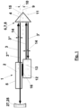
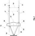
- the optical arrangement 1 shown comprises a light source 2 which emits a light beam 3 in the direction of a first optical axis 4. A position of the first optical axis 4 relative to a mechanical structure 5 of the light source 2 is fixed.
- the optical arrangement 1 further comprises a first reflector 6 in the form of a retroreflector 7.
- the retroreflector 7 is specifically designed here as a triple prism 8.
- the retroreflector 7 is arranged offset with respect to its main axis 9 by a dimension 10 transversely to the first optical axis 4.
- the retroreflector 7 reflects the light beam 3 'in the direction of a second optical axis 11, which is offset parallel to the first optical axis 4 in the transverse direction by twice the dimension 10.
- the light beam reflected by the retroreflector 7 is provided with the reference number 3' in the figures.
- the reflected light beam 3 ' impacts a second reflector 12 of the optical arrangement 1.
- the second reflector 12 is designed such that it in turn reflects the reflected light beam 3' in the direction of a third optical axis 13, which is fixed by a fixed dimension 14 Transverse direction is offset parallel to the second optical axis 11.
- the fixed dimension 14 only looks different in size because it is in the fixed transverse direction at different angles to the viewing directions of the Fig. 1 and 2 runs.
- the light beam reflected by the second reflector 12 is provided with the reference number 3" in the figures.
- the reflected light beam 3" reaches the retroreflector 7 again, from which it is reflected in the direction of a fourth optical axis 15.
- the fourth optical axis 15 is offset in parallel with respect to the first optical axis 4 by the same fixed dimension 14 as the third optical axis 13 with respect to the second optical axis 11, but opposite to the fixed transverse direction.
- the light beam reflected again by the retroreflector 7 along the optical axis 15 is provided with the reference number 3′′′ in the figures.
- the fixed positional relationship of the fourth optical axis 15 to the first optical axis 4 is based solely on a fixed orientation of the second reflector 12 relative to the mechanical structure 5 of the light source 2.
- a fixed position or orientation of the first reflector 6 relative to the light source 2 is not a prerequisite for this . This is explained below using the Fig. 8 to 10 will be explained in more detail.
- the fixed alignment of the second reflector 12 relative to the mechanical structure 5 of the light source 2 is achieved by fastening 16 of the second reflector 12 to the mechanical structure 5, whereby the Fastening does not have to be unchangeably rigid. Rather, adjustment devices can be present here in order to align the second reflector 12 with respect to the first optical axis 4 as desired.
- the parallel offset introduced by the second reflector between the second optical axis 11 and the third optical axis 13 is by this fixed dimension 14 and the parallel offset between the first optical axis 4 and the second optical axis 11 introduced by the retroreflector 7 are folded by twice the dimension 10, so that they do not completely but partially compensate for each other.
- An angle 29 between the transverse offset of the retroreflector 7 the first optical axis 4 by the dimension 10 and the parallel offset of the fourth optical axis 15 resulting from the second reflector 12 relative to the first optical axis 4 by the fixed dimension 14 is acute and is here approximately 30 °.
- the fixed dimension 14 of the parallel offset of the fourth optical axis 15 compared to the first optical axis 4 is approximately 2 times the dimension 10 of the transverse offset of the retroreflector multiplied by the cosine of the angle 29. This is how it is Fig. 3 the first optical axis 4 at a certain vertical distance above the third optical axis 13 and the fourth optical axis 15 at the same vertical distance above the second optical axis 11.
- a third reflector 27 for example in the form of a convex mirror 28, can be arranged on the fourth optical axis 15, which is curved about a point on the fourth optical axis 15 and which, for example, delimits a LASER resonator on one side, in the LASER -Material is pumped into the light source 2.
- the third reflector 27 can be different than in the Fig. 1 and 2 indicated also be attached to the mechanical structure 5 of the light source 2.
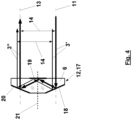
- Fig. 4 illustrates a first embodiment of the second optical reflector 12 in the form of a prism 17 with three flat surfaces 18, 19 and 20 reflecting the light beam 3 '.
- One flat surface 19 is aligned orthogonally to the optical axes 11 and 13, and the other two Flat surfaces 18 and 20 are arranged axially symmetrically to a surface normal 21 of the flat surface 19, with surface normals of all three flat surfaces 18 to 20 into the drawing layer of Fig. 4 fall.
- the light beam 3" reflected by the second reflector 12 in the direction of the third optical axis 13 is always parallel offset in the same transverse direction by the same fixed dimension 14 compared to the light beam 3' incident in the direction of the second optical axis 11.
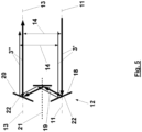
- Fig. 5 shows one according to the second reflector 12 Fig. 4 equivalent second reflector 12, in which the flat surfaces 18 to 20 reflecting the light beam 3 'are formed on three flat mirrors 22.
- the embodiment of the second reflector shown is a further prism 33.
- the light beam 3 ' is deflected by a refracting flat surface 34 before it is oriented orthogonally to the optical axes 11 and 13 by the reflecting flat surface 19 is reflected.
- the light beam 3' is deflected by a further refracting flat surface 35, so that the light beam 3" reflected by the second reflector 12 runs parallel to the incident light beam 3'.
- the two refracting optical surfaces 34 and 35 directly to one another. In this way, the area normal to the optical axis 11, in which the light beam 3 'can impinge on the second reflector 12, is particularly large.
- Fig. 7 shows one according to the second reflector 12 Fig. 6 equivalent second reflector 12, in which the plane surface 19 reflecting the light beam 3 'is formed on a plane mirror 22, which is spaced from the prism 33 in the direction of the optical axes 11 and 13.
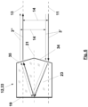
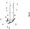
- the embodiment of the second reflector 12 shown is another prism 23.
- three flat surfaces 18 to 20 are formed on the prism 23, which successively reflect the light beam 3 '.
- the flat surface 20 is aligned at an angle of 45 ° to the optical axes 11 and 13 and deflects the light beam 3 'by 90 °.
- the other two flat surfaces 18 and 19 together also deflect the light beam 3 'by 90 °.
- the reflected light beam 3" is always parallel offset in the same transverse direction by the same fixed amount 14 relative to the incident light beam 3'.
- Fig. 9 illustrates that pivoting the prism 23 according to Fig. 8 the fixed dimension 14 of the parallel offset between the incident light beam 3 'and the light beam 3" reflected by the second reflector 12 does not change.
- the fixed dimension 14 remains parallel and perpendicular to the plane of the drawing even when the prism 23 is displaced Fig. 9 firmly.
- rotations of the prism 13 about the optical axes 11 and 13 change the direction of the parallel offset by the fixed dimension 14 and are therefore not permitted.
- the second reflector 12 must be immovable on the mechanical structure 5 of the light source 2, at least with respect to rotations about the optical axes 11 and 13 and the first optical axis 4 parallel thereto Fig. 1 to 3 be attached.
- Fig. 10 shows an embodiment of the second reflector 12, which corresponds to that according to Fig. 8 and 9 is equivalent, but is constructed from plane mirrors 22.
- Fig. 11 (a) shows the optical arrangement 1 according to Fig. 1 to 3 in the same direction as Fig. 3 .
- An arrow points 24 in Fig. 8 (a) a downward displacement of the retroreflector 7, which is shown in Fig. 11 (b) is realized.
- the second optical axis 11 and thus also the third optical axis 13 shift further downward.
- the fourth optical axis 15 is shifted further upwards relative to the second optical axis 11 and the third optical axis 13, the fourth optical axis 15 is again at the same height as the first optical axis 4, and it is by the same fixed amount 14 is parallel offset against the horizontal transverse direction relative to the first optical axis 4, in which the third optical axis 13 is parallel offset relative to the second optical axis 11 by the fixed dimension 14.
- Fig. 12 accordingly shows the effects of a horizontal displacement of the retroreflector 7 to the right in the direction of an in Fig. 9 (a) shown arrow 25. This also shifts the second optical axis 11 to the right. However, this is compensated for by the retroreflector 7 between the third optical axis 13 and the fourth optical axis 15, so that here too the fourth optical axis 15 is offset parallel to the first optical axis 4 by the same fixed amount 14 against the horizontal transverse direction, in which the third optical axis 13 is offset parallel to the second optical axis 11 by the fixed dimension 14.
- Fig. 13 illustrates the effect of rotating the retroreflector 7 about its main axis 9 in the direction of an in Fig. 10 (a) shown rotation arrow 26. This rotation does not affect the position of the second optical axis 11 relative to the first optical axis 4.
- Fig. 14 illustrates the effect of a tilting of the main axis 9 relative to the first optical axis 4 by an angle 31.
- This angle 31 has the effect of a change in the parallel offset between the two optical axes 4 and 11, which is correspondingly due to the parallel offset between the optical axes 13 and 15 are balanced.
- FIG. 11 to 14 show Fig. 11 to 14 that the position and orientation of the retroreflector 7 designed as a triple prism 8 is irrelevant for the position of the fourth optical axis 15 relative to the first optical axis 4.
- Any position and orientation changes of the retroreflector can be represented using the individually displayed changes in position and orientation.
- Fig. 15 shows a LASER interferometer 34 according to the invention with the optical arrangement 1 according to the invention.
- a LASER beam 35 coming from the light source 2 is split with a beam splitter 36 into the light beam 3 and a light beam 37 that is coherent therewith.
- a further beam splitter 38 With the help of a further beam splitter 38, the light beam 3′′′ reflected along the fourth optical axis 15 by the first reflector 6 and the light beam 37 coherent therewith are superimposed, resulting in two complementary interference signals 39 and 40, which are detected by two detectors 41 and 42.
- the beam splitters 38 are rigidly connected to the mechanical structure 5 of the light source 2.
- the detectors 41 and 42 can, but do not have to be, connected to the mechanical structure 5.
- the two complementary interference signals 39 and 40 change and thus allow changes in this distance to be recorded precisely.
- other changes in the orientation of the position of the first reflector 6 are compensated for by the optical arrangement 1.
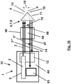
- Fig. 16 shows a LASER spectrometer 52 according to the invention, in which the light source 2, the second reflector 12 and a detector 43 are arranged in a common housing 44 on one side of a measuring volume 45, while the first reflector 6 is on the opposite side of the measuring volume 45.
- the measuring volume is limited here by a wall 46.
- the light beam 3 enters and leaves the measuring volume 45 four times through windows 47 and 48 and then reaches the detector 43, which is relative to the mechanical structure, regardless of the current position and orientation of the first reflector 6 (retroreflector 7). 5 of the light source 2 is fixed.
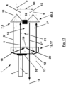
- Fig. 17 shows an alternative embodiment of the optical arrangement 1, in which the second reflector 12 is in the form of a prism 17 as in Fig. 4 reflected light beam 3" not again from the first reflector 6, but from a retroreflector 49 rigidly coupled thereto is reflected.
- a fastening 32 is shown.
- the retroreflector 49 is also designed as a triple prism, specifically here just like the first reflector 6.
- the two retroreflectors 7 and 49 are arranged at a fixed distance 50 transversely to the third optical axis 13.
- the fixed distance 50 is also present here between the main axes of the two retroreflectors 7 and 49.
- the fixed distance 50 has a fixed angle to the transverse offset with the fixed dimension 14 between the second optical axis 11 and the third optical axis 13, or it runs parallel thereto. This means that the unit with the two retroreflectors 7 and 49 must not be rotated about one of the optical axes 4, 11, 13 and 15, because the angle between the distance 15 and the transverse offset would then change with the fixed dimension 14.
- the transverse offset between the first optical axis 4 and the fourth optical axis 15 has a further fixed dimension 51.
- this further fixed dimension 51 is only equal to the fixed dimension 14 if the distance 50 times the cosine of any angle between the fixed distance 50 and the transverse offset with the fixed dimension 14 is equal to the fixed dimension 14.
- the transverse offset with the further fixed dimension 51 only runs exactly in the direction of the transverse offset with the fixed dimension 14 if the fixed distance 15 and the transverse offset with the fixed dimension 14 run parallel to one another.
- the transverse offset between the first optical axis 4 and the fourth optical axis 15 in this alternative embodiment of the optical arrangement 1 also has the same direction as the transverse offset between the second optical axis 11 and the third optical axis 13 on.
- Another special feature is that the light beam 3 coming from the light source 2 also passes through the prism 17 here.
Landscapes
- Physics & Mathematics (AREA)
- Spectroscopy & Molecular Physics (AREA)
- Electromagnetism (AREA)
- Engineering & Computer Science (AREA)
- Plasma & Fusion (AREA)
- Optics & Photonics (AREA)
- General Physics & Mathematics (AREA)
- Life Sciences & Earth Sciences (AREA)
- Health & Medical Sciences (AREA)
- Chemical & Material Sciences (AREA)
- Analytical Chemistry (AREA)
- Biochemistry (AREA)
- General Health & Medical Sciences (AREA)
- Immunology (AREA)
- Pathology (AREA)
- Instruments For Measurement Of Length By Optical Means (AREA)
- Optical Elements Other Than Lenses (AREA)
- Spectrometry And Color Measurement (AREA)
- Lasers (AREA)
Applications Claiming Priority (2)
| Application Number | Priority Date | Filing Date | Title |
|---|---|---|---|
| DE102016113049.4A DE102016113049A1 (de) | 2016-07-15 | 2016-07-15 | Optische Anordnung zur Kompensation von Fehlausrichtungen eines Reflektors gegenüber einer Lichtquelle |
| PCT/EP2017/067722 WO2018011350A1 (de) | 2016-07-15 | 2017-07-13 | Optische anordnung zur kompensation von fehlausrichtungen eines reflektors gegenüber einer lichtquelle |
Publications (2)
| Publication Number | Publication Date |
|---|---|
| EP3485247A1 EP3485247A1 (de) | 2019-05-22 |
| EP3485247B1 true EP3485247B1 (de) | 2024-03-13 |
Family
ID=59337680
Family Applications (1)
| Application Number | Title | Priority Date | Filing Date |
|---|---|---|---|
| EP17739571.2A Active EP3485247B1 (de) | 2016-07-15 | 2017-07-13 | Optische anordnung zur kompensation von fehlausrichtungen eines reflektors gegenüber einer lichtquelle |
Country Status (7)
| Country | Link |
|---|---|
| US (1) | US11248956B2 (pl) |
| EP (1) | EP3485247B1 (pl) |
| JP (1) | JP7061106B2 (pl) |
| CN (1) | CN109477760B (pl) |
| DE (1) | DE102016113049A1 (pl) |
| PL (1) | PL3485247T3 (pl) |
| WO (1) | WO2018011350A1 (pl) |
Families Citing this family (5)
| Publication number | Priority date | Publication date | Assignee | Title |
|---|---|---|---|---|
| DE102018208147A1 (de) * | 2018-05-24 | 2019-11-28 | Carl Zeiss Smt Gmbh | Messanordnung zur frequenszbasierten Positionsbestimmung einer Komponente |
| CN110970786A (zh) * | 2019-11-20 | 2020-04-07 | 湖北华中光电科技有限公司 | 一种小型折叠腔人眼安全激光器 |
| GB2593195B (en) * | 2020-03-18 | 2023-02-22 | Thermo Fisher Scient Ecublens Sarl | Multipass cell |
| GB2593456B (en) * | 2020-03-18 | 2024-02-28 | Thermo Fisher Scient Ecublens Sarl | Double-pulse laser system |
| CN114069374B (zh) * | 2020-07-29 | 2024-07-12 | 刘建圣 | 激光稳源系统与激光源模块 |
Family Cites Families (32)
| Publication number | Priority date | Publication date | Assignee | Title |
|---|---|---|---|---|
| JPS5360779U (pl) * | 1976-10-26 | 1978-05-23 | ||
| GB2049267B (en) * | 1979-04-17 | 1983-03-16 | Ferranti Ltd | Laser apparatus |
| DE3005520C2 (de) * | 1980-02-14 | 1983-05-05 | Kayser-Threde GmbH, 8000 München | Zweistrahl-Interferometer zur Fourierspektroskopie |
| JPS58157186A (ja) * | 1982-03-13 | 1983-09-19 | Toshiba Corp | ガスレ−ザ装置 |
| JPS5968983A (ja) * | 1982-10-13 | 1984-04-19 | Hitachi Ltd | レ−ザ発生装置 |
| US4544272A (en) | 1983-03-04 | 1985-10-01 | Laser Precision Corporation | Alignment apparatus and method for interferometer spectrometers |
| JPS61187386A (ja) * | 1985-02-15 | 1986-08-21 | Mitsubishi Electric Corp | レ−ザ発振器 |
| JPS63143886A (ja) * | 1986-12-03 | 1988-06-16 | アマダ エンジニアリング アンド サ−ビス カンパニ− インコ−ポレ−テツド | 光軸立体折返し型レ−ザ共振器 |
| JPH01233784A (ja) * | 1988-03-15 | 1989-09-19 | Mitsubishi Electric Corp | レーザ発振器 |
| DE3813572A1 (de) * | 1988-04-22 | 1989-11-02 | Fraunhofer Ges Forschung | Laser |
| DE4004071C2 (de) * | 1990-02-08 | 1994-05-05 | Festkoerper Laser Inst Berlin | Optischer Resonator für Festkörperlaser |
| US5220463A (en) * | 1991-01-29 | 1993-06-15 | Clark Instrumentation, Inc. | Optical delay line |
| JP2872855B2 (ja) * | 1992-02-19 | 1999-03-24 | ファナック株式会社 | レーザ発振器 |
| JP2846521B2 (ja) * | 1992-03-30 | 1999-01-13 | ファナック株式会社 | レーザ発振装置 |
| US5251221A (en) * | 1992-08-10 | 1993-10-05 | Hughes Aircraft Company | Self aligning intracavity Raman laser |
| JPH07211972A (ja) * | 1994-01-20 | 1995-08-11 | Fanuc Ltd | レーザ発振器 |
| US5923695A (en) | 1997-06-11 | 1999-07-13 | Raytheon Company | Compact pumped laser resonator and method |
| JP3591360B2 (ja) * | 1999-03-03 | 2004-11-17 | 富士電機システムズ株式会社 | レーザ発振装置 |
| US6373866B1 (en) * | 2000-01-26 | 2002-04-16 | Lumenis Inc. | Solid-state laser with composite prismatic gain-region |
| JP3619106B2 (ja) * | 2000-02-22 | 2005-02-09 | 三菱電機株式会社 | 自己補償形レーザ共振器 |
| JP4147785B2 (ja) * | 2002-02-27 | 2008-09-10 | 株式会社ニコン | 干渉計、露光装置、露光方法及びステージ装置 |
| FI20031581A0 (fi) * | 2003-10-30 | 2003-10-30 | Noveltech Solutions Ltd | Interferometri |
| US7259856B2 (en) * | 2005-02-16 | 2007-08-21 | Picarro, Inc. | Method for the precise measurement of the wavelength of light |
| DE102007010841A1 (de) * | 2007-03-04 | 2008-09-11 | Du, Keming, Dr. | Multistufige Verstärker-Anordnungen |
| US7652771B2 (en) * | 2007-10-31 | 2010-01-26 | Agilent Technologies, Inc. | Interferometer with Double Polarizing Beam Splitter |
| US8204094B2 (en) * | 2009-04-21 | 2012-06-19 | Innova, Inc. | Scalable, efficient laser systems |
| US20120103099A1 (en) * | 2010-10-29 | 2012-05-03 | Stuke Michael J | Laser vibration sensor, system and method |
| US9212990B1 (en) * | 2011-12-06 | 2015-12-15 | Zybertec Llc | System and methods for molecular detection using intracavity laser absorption spectroscopy |
| EP2604999A1 (de) | 2011-12-15 | 2013-06-19 | Mettler-Toledo AG | Gasmessgerät |
| GB201214899D0 (en) * | 2012-08-21 | 2012-10-03 | Stfc Science & Technology | Method and apparatus for external cavity laser absorption spectroscopy |
| US10119816B2 (en) * | 2012-11-21 | 2018-11-06 | Nikon Metrology Nv | Low drift reference for laser radar |
| CN105406338A (zh) * | 2015-12-14 | 2016-03-16 | 中国人民解放军武汉军械士官学校 | 一种基于角锥棱镜的小型多级放大激光装置 |
-
2016
- 2016-07-15 DE DE102016113049.4A patent/DE102016113049A1/de not_active Withdrawn
-
2017
- 2017-07-13 EP EP17739571.2A patent/EP3485247B1/de active Active
- 2017-07-13 JP JP2019501614A patent/JP7061106B2/ja active Active
- 2017-07-13 WO PCT/EP2017/067722 patent/WO2018011350A1/de not_active Ceased
- 2017-07-13 US US16/318,038 patent/US11248956B2/en active Active
- 2017-07-13 CN CN201780043932.6A patent/CN109477760B/zh active Active
- 2017-07-13 PL PL17739571.2T patent/PL3485247T3/pl unknown
Also Published As
| Publication number | Publication date |
|---|---|
| PL3485247T3 (pl) | 2024-07-22 |
| EP3485247A1 (de) | 2019-05-22 |
| WO2018011350A1 (de) | 2018-01-18 |
| JP2019527479A (ja) | 2019-09-26 |
| CN109477760A (zh) | 2019-03-15 |
| DE102016113049A1 (de) | 2018-01-18 |
| US20210278276A1 (en) | 2021-09-09 |
| CN109477760B (zh) | 2021-04-02 |
| JP7061106B2 (ja) | 2022-04-27 |
| US11248956B2 (en) | 2022-02-15 |
Similar Documents
| Publication | Publication Date | Title |
|---|---|---|
| EP3485247B1 (de) | Optische anordnung zur kompensation von fehlausrichtungen eines reflektors gegenüber einer lichtquelle | |
| EP0146768B1 (de) | Interferometer | |
| EP0829120B1 (de) | Durchstimmbare, justierstabile laserlichtquelle mit spektral gefiltertem ausgang | |
| EP0750174B1 (de) | Referenzinterferometer mit variabler Wellenlänge | |
| EP3420304B1 (de) | Vermessung einer kavität mittels interferenzspektroskopie | |
| EP2980525B1 (de) | Triple-pass interferometer | |
| EP3054280A1 (de) | Optisches Messgerät und Verfahren zur Gasdetektion | |
| DE3943373C2 (de) | Gefalteter Wellenleiterlaser | |
| EP2706340A2 (de) | Vorrichtung und verfahren zum prüfen der ausrichtung wenigstens einer optischen fläche eines optischen systems | |
| DE68922135T2 (de) | Laser Interferometer mit optischer Rückkopplungsisolation. | |
| DE19913049C2 (de) | Verfahren und Vorrichtung zur Bestimmung der Geschwindigkeit | |
| DE3431040C2 (de) | Interferometer | |
| DE3140086A1 (de) | "optische trenneinrichtung mit einem fizeau'schen-keil in reflexion" | |
| EP0801451A2 (de) | Abstimmvorrichtung | |
| DE3626524C1 (de) | Optisches Autokollimations-Messgeraet | |
| DE2508860C3 (de) | Optische Mehrfachreflexionsanordnung | |
| DD267787A1 (de) | Interferometrisches messsystem mit wellenlaengenkorrektureinrichtung des laserlichtes, insbesondere fuer laengenmessungen | |
| WO2001014837A1 (de) | Michelson-interferometer mit kalibrationsvorrichtung | |
| DE3930912A1 (de) | Vorrichtung zum ueberpruefen der parallelitaet zweier achsen | |
| DE3616392C1 (en) | Device for interferometric alignment measurement between two different jointly rotatable shafts | |
| DE3838357C2 (pl) | ||
| DE3419024A1 (de) | Laserinterferometrisches winkelmessgeraet | |
| EP3707542B1 (de) | Optisches system | |
| WO2008019937A1 (de) | Michelson-interferometer | |
| DE4322687C1 (de) | Interferometer nach Michelson |
Legal Events
| Date | Code | Title | Description |
|---|---|---|---|
| STAA | Information on the status of an ep patent application or granted ep patent |
Free format text: STATUS: UNKNOWN |
|
| STAA | Information on the status of an ep patent application or granted ep patent |
Free format text: STATUS: THE INTERNATIONAL PUBLICATION HAS BEEN MADE |
|
| PUAI | Public reference made under article 153(3) epc to a published international application that has entered the european phase |
Free format text: ORIGINAL CODE: 0009012 |
|
| STAA | Information on the status of an ep patent application or granted ep patent |
Free format text: STATUS: REQUEST FOR EXAMINATION WAS MADE |
|
| 17P | Request for examination filed |
Effective date: 20190205 |
|
| AK | Designated contracting states |
Kind code of ref document: A1 Designated state(s): AL AT BE BG CH CY CZ DE DK EE ES FI FR GB GR HR HU IE IS IT LI LT LU LV MC MK MT NL NO PL PT RO RS SE SI SK SM TR |
|
| AX | Request for extension of the european patent |
Extension state: BA ME |
|
| DAV | Request for validation of the european patent (deleted) | ||
| DAX | Request for extension of the european patent (deleted) | ||
| STAA | Information on the status of an ep patent application or granted ep patent |
Free format text: STATUS: EXAMINATION IS IN PROGRESS |
|
| 17Q | First examination report despatched |
Effective date: 20220118 |
|
| REG | Reference to a national code |
Ref country code: DE Ref legal event code: R079 Free format text: PREVIOUS MAIN CLASS: G01J0003453000 Ipc: H01S0003020000 Ref country code: DE Ref legal event code: R079 Ref document number: 502017015924 Country of ref document: DE Free format text: PREVIOUS MAIN CLASS: G01J0003453000 Ipc: H01S0003020000 |
|
| GRAP | Despatch of communication of intention to grant a patent |
Free format text: ORIGINAL CODE: EPIDOSNIGR1 |
|
| STAA | Information on the status of an ep patent application or granted ep patent |
Free format text: STATUS: GRANT OF PATENT IS INTENDED |
|
| RIC1 | Information provided on ipc code assigned before grant |
Ipc: H01S 3/094 20060101ALI20231006BHEP Ipc: H01S 3/086 20060101ALI20231006BHEP Ipc: H01S 3/02 20060101AFI20231006BHEP |
|
| INTG | Intention to grant announced |
Effective date: 20231102 |
|
| GRAS | Grant fee paid |
Free format text: ORIGINAL CODE: EPIDOSNIGR3 |
|
| GRAA | (expected) grant |
Free format text: ORIGINAL CODE: 0009210 |
|
| STAA | Information on the status of an ep patent application or granted ep patent |
Free format text: STATUS: THE PATENT HAS BEEN GRANTED |
|
| AK | Designated contracting states |
Kind code of ref document: B1 Designated state(s): AL AT BE BG CH CY CZ DE DK EE ES FI FR GB GR HR HU IE IS IT LI LT LU LV MC MK MT NL NO PL PT RO RS SE SI SK SM TR |
|
| REG | Reference to a national code |
Ref country code: GB Ref legal event code: FG4D Free format text: NOT ENGLISH |
|
| REG | Reference to a national code |
Ref country code: CH Ref legal event code: EP |
|
| REG | Reference to a national code |
Ref country code: DE Ref legal event code: R096 Ref document number: 502017015924 Country of ref document: DE |
|
| REG | Reference to a national code |
Ref country code: IE Ref legal event code: FG4D Free format text: LANGUAGE OF EP DOCUMENT: GERMAN |
|
| REG | Reference to a national code |
Ref country code: SE Ref legal event code: TRGR |
|
| PG25 | Lapsed in a contracting state [announced via postgrant information from national office to epo] |
Ref country code: LT Free format text: LAPSE BECAUSE OF FAILURE TO SUBMIT A TRANSLATION OF THE DESCRIPTION OR TO PAY THE FEE WITHIN THE PRESCRIBED TIME-LIMIT Effective date: 20240313 |
|
| REG | Reference to a national code |
Ref country code: NL Ref legal event code: FP Ref country code: LT Ref legal event code: MG9D |
|
| PG25 | Lapsed in a contracting state [announced via postgrant information from national office to epo] |
Ref country code: GR Free format text: LAPSE BECAUSE OF FAILURE TO SUBMIT A TRANSLATION OF THE DESCRIPTION OR TO PAY THE FEE WITHIN THE PRESCRIBED TIME-LIMIT Effective date: 20240614 |
|
| PG25 | Lapsed in a contracting state [announced via postgrant information from national office to epo] |
Ref country code: HR Free format text: LAPSE BECAUSE OF FAILURE TO SUBMIT A TRANSLATION OF THE DESCRIPTION OR TO PAY THE FEE WITHIN THE PRESCRIBED TIME-LIMIT Effective date: 20240313 Ref country code: RS Free format text: LAPSE BECAUSE OF FAILURE TO SUBMIT A TRANSLATION OF THE DESCRIPTION OR TO PAY THE FEE WITHIN THE PRESCRIBED TIME-LIMIT Effective date: 20240613 |
|
| PG25 | Lapsed in a contracting state [announced via postgrant information from national office to epo] |
Ref country code: ES Free format text: LAPSE BECAUSE OF FAILURE TO SUBMIT A TRANSLATION OF THE DESCRIPTION OR TO PAY THE FEE WITHIN THE PRESCRIBED TIME-LIMIT Effective date: 20240313 |
|
| PG25 | Lapsed in a contracting state [announced via postgrant information from national office to epo] |
Ref country code: RS Free format text: LAPSE BECAUSE OF FAILURE TO SUBMIT A TRANSLATION OF THE DESCRIPTION OR TO PAY THE FEE WITHIN THE PRESCRIBED TIME-LIMIT Effective date: 20240613 Ref country code: LT Free format text: LAPSE BECAUSE OF FAILURE TO SUBMIT A TRANSLATION OF THE DESCRIPTION OR TO PAY THE FEE WITHIN THE PRESCRIBED TIME-LIMIT Effective date: 20240313 Ref country code: HR Free format text: LAPSE BECAUSE OF FAILURE TO SUBMIT A TRANSLATION OF THE DESCRIPTION OR TO PAY THE FEE WITHIN THE PRESCRIBED TIME-LIMIT Effective date: 20240313 Ref country code: GR Free format text: LAPSE BECAUSE OF FAILURE TO SUBMIT A TRANSLATION OF THE DESCRIPTION OR TO PAY THE FEE WITHIN THE PRESCRIBED TIME-LIMIT Effective date: 20240614 Ref country code: FI Free format text: LAPSE BECAUSE OF FAILURE TO SUBMIT A TRANSLATION OF THE DESCRIPTION OR TO PAY THE FEE WITHIN THE PRESCRIBED TIME-LIMIT Effective date: 20240313 Ref country code: ES Free format text: LAPSE BECAUSE OF FAILURE TO SUBMIT A TRANSLATION OF THE DESCRIPTION OR TO PAY THE FEE WITHIN THE PRESCRIBED TIME-LIMIT Effective date: 20240313 Ref country code: BG Free format text: LAPSE BECAUSE OF FAILURE TO SUBMIT A TRANSLATION OF THE DESCRIPTION OR TO PAY THE FEE WITHIN THE PRESCRIBED TIME-LIMIT Effective date: 20240313 |
|
| PG25 | Lapsed in a contracting state [announced via postgrant information from national office to epo] |
Ref country code: LV Free format text: LAPSE BECAUSE OF FAILURE TO SUBMIT A TRANSLATION OF THE DESCRIPTION OR TO PAY THE FEE WITHIN THE PRESCRIBED TIME-LIMIT Effective date: 20240313 |
|
| PG25 | Lapsed in a contracting state [announced via postgrant information from national office to epo] |
Ref country code: IS Free format text: LAPSE BECAUSE OF FAILURE TO SUBMIT A TRANSLATION OF THE DESCRIPTION OR TO PAY THE FEE WITHIN THE PRESCRIBED TIME-LIMIT Effective date: 20240713 |
|
| PG25 | Lapsed in a contracting state [announced via postgrant information from national office to epo] |
Ref country code: PT Free format text: LAPSE BECAUSE OF FAILURE TO SUBMIT A TRANSLATION OF THE DESCRIPTION OR TO PAY THE FEE WITHIN THE PRESCRIBED TIME-LIMIT Effective date: 20240715 Ref country code: SM Free format text: LAPSE BECAUSE OF FAILURE TO SUBMIT A TRANSLATION OF THE DESCRIPTION OR TO PAY THE FEE WITHIN THE PRESCRIBED TIME-LIMIT Effective date: 20240313 |
|
| PG25 | Lapsed in a contracting state [announced via postgrant information from national office to epo] |
Ref country code: EE Free format text: LAPSE BECAUSE OF FAILURE TO SUBMIT A TRANSLATION OF THE DESCRIPTION OR TO PAY THE FEE WITHIN THE PRESCRIBED TIME-LIMIT Effective date: 20240313 Ref country code: CZ Free format text: LAPSE BECAUSE OF FAILURE TO SUBMIT A TRANSLATION OF THE DESCRIPTION OR TO PAY THE FEE WITHIN THE PRESCRIBED TIME-LIMIT Effective date: 20240313 |
|
| PG25 | Lapsed in a contracting state [announced via postgrant information from national office to epo] |
Ref country code: SK Free format text: LAPSE BECAUSE OF FAILURE TO SUBMIT A TRANSLATION OF THE DESCRIPTION OR TO PAY THE FEE WITHIN THE PRESCRIBED TIME-LIMIT Effective date: 20240313 |
|
| PG25 | Lapsed in a contracting state [announced via postgrant information from national office to epo] |
Ref country code: SM Free format text: LAPSE BECAUSE OF FAILURE TO SUBMIT A TRANSLATION OF THE DESCRIPTION OR TO PAY THE FEE WITHIN THE PRESCRIBED TIME-LIMIT Effective date: 20240313 Ref country code: SK Free format text: LAPSE BECAUSE OF FAILURE TO SUBMIT A TRANSLATION OF THE DESCRIPTION OR TO PAY THE FEE WITHIN THE PRESCRIBED TIME-LIMIT Effective date: 20240313 Ref country code: RO Free format text: LAPSE BECAUSE OF FAILURE TO SUBMIT A TRANSLATION OF THE DESCRIPTION OR TO PAY THE FEE WITHIN THE PRESCRIBED TIME-LIMIT Effective date: 20240313 Ref country code: PT Free format text: LAPSE BECAUSE OF FAILURE TO SUBMIT A TRANSLATION OF THE DESCRIPTION OR TO PAY THE FEE WITHIN THE PRESCRIBED TIME-LIMIT Effective date: 20240715 Ref country code: IS Free format text: LAPSE BECAUSE OF FAILURE TO SUBMIT A TRANSLATION OF THE DESCRIPTION OR TO PAY THE FEE WITHIN THE PRESCRIBED TIME-LIMIT Effective date: 20240713 Ref country code: EE Free format text: LAPSE BECAUSE OF FAILURE TO SUBMIT A TRANSLATION OF THE DESCRIPTION OR TO PAY THE FEE WITHIN THE PRESCRIBED TIME-LIMIT Effective date: 20240313 Ref country code: CZ Free format text: LAPSE BECAUSE OF FAILURE TO SUBMIT A TRANSLATION OF THE DESCRIPTION OR TO PAY THE FEE WITHIN THE PRESCRIBED TIME-LIMIT Effective date: 20240313 |
|
| PG25 | Lapsed in a contracting state [announced via postgrant information from national office to epo] |
Ref country code: IT Free format text: LAPSE BECAUSE OF FAILURE TO SUBMIT A TRANSLATION OF THE DESCRIPTION OR TO PAY THE FEE WITHIN THE PRESCRIBED TIME-LIMIT Effective date: 20240313 |
|
| REG | Reference to a national code |
Ref country code: DE Ref legal event code: R097 Ref document number: 502017015924 Country of ref document: DE |
|
| PG25 | Lapsed in a contracting state [announced via postgrant information from national office to epo] |
Ref country code: IT Free format text: LAPSE BECAUSE OF FAILURE TO SUBMIT A TRANSLATION OF THE DESCRIPTION OR TO PAY THE FEE WITHIN THE PRESCRIBED TIME-LIMIT Effective date: 20240313 |
|
| PG25 | Lapsed in a contracting state [announced via postgrant information from national office to epo] |
Ref country code: DK Free format text: LAPSE BECAUSE OF FAILURE TO SUBMIT A TRANSLATION OF THE DESCRIPTION OR TO PAY THE FEE WITHIN THE PRESCRIBED TIME-LIMIT Effective date: 20240313 |
|
| PLBE | No opposition filed within time limit |
Free format text: ORIGINAL CODE: 0009261 |
|
| STAA | Information on the status of an ep patent application or granted ep patent |
Free format text: STATUS: NO OPPOSITION FILED WITHIN TIME LIMIT |
|
| PG25 | Lapsed in a contracting state [announced via postgrant information from national office to epo] |
Ref country code: DK Free format text: LAPSE BECAUSE OF FAILURE TO SUBMIT A TRANSLATION OF THE DESCRIPTION OR TO PAY THE FEE WITHIN THE PRESCRIBED TIME-LIMIT Effective date: 20240313 |
|
| PG25 | Lapsed in a contracting state [announced via postgrant information from national office to epo] |
Ref country code: MC Free format text: LAPSE BECAUSE OF FAILURE TO SUBMIT A TRANSLATION OF THE DESCRIPTION OR TO PAY THE FEE WITHIN THE PRESCRIBED TIME-LIMIT Effective date: 20240313 |
|
| 26N | No opposition filed |
Effective date: 20241216 |
|
| PG25 | Lapsed in a contracting state [announced via postgrant information from national office to epo] |
Ref country code: LU Free format text: LAPSE BECAUSE OF NON-PAYMENT OF DUE FEES Effective date: 20240713 |
|
| PG25 | Lapsed in a contracting state [announced via postgrant information from national office to epo] |
Ref country code: LU Free format text: LAPSE BECAUSE OF NON-PAYMENT OF DUE FEES Effective date: 20240713 |
|
| PG25 | Lapsed in a contracting state [announced via postgrant information from national office to epo] |
Ref country code: SI Free format text: LAPSE BECAUSE OF FAILURE TO SUBMIT A TRANSLATION OF THE DESCRIPTION OR TO PAY THE FEE WITHIN THE PRESCRIBED TIME-LIMIT Effective date: 20240313 |
|
| PGFP | Annual fee paid to national office [announced via postgrant information from national office to epo] |
Ref country code: PL Payment date: 20250624 Year of fee payment: 9 |
|
| PG25 | Lapsed in a contracting state [announced via postgrant information from national office to epo] |
Ref country code: IE Free format text: LAPSE BECAUSE OF NON-PAYMENT OF DUE FEES Effective date: 20240713 |
|
| PGFP | Annual fee paid to national office [announced via postgrant information from national office to epo] |
Ref country code: NL Payment date: 20250724 Year of fee payment: 9 |
|
| REG | Reference to a national code |
Ref country code: AT Ref legal event code: MM01 Ref document number: 1666658 Country of ref document: AT Kind code of ref document: T Effective date: 20240713 |
|
| PGFP | Annual fee paid to national office [announced via postgrant information from national office to epo] |
Ref country code: DE Payment date: 20250714 Year of fee payment: 9 |
|
| PGFP | Annual fee paid to national office [announced via postgrant information from national office to epo] |
Ref country code: NO Payment date: 20250718 Year of fee payment: 9 |
|
| PGFP | Annual fee paid to national office [announced via postgrant information from national office to epo] |
Ref country code: GB Payment date: 20250722 Year of fee payment: 9 Ref country code: BE Payment date: 20250724 Year of fee payment: 9 |
|
| PG25 | Lapsed in a contracting state [announced via postgrant information from national office to epo] |
Ref country code: AT Free format text: LAPSE BECAUSE OF NON-PAYMENT OF DUE FEES Effective date: 20240713 |
|
| PGFP | Annual fee paid to national office [announced via postgrant information from national office to epo] |
Ref country code: FR Payment date: 20250725 Year of fee payment: 9 |
|
| PGFP | Annual fee paid to national office [announced via postgrant information from national office to epo] |
Ref country code: CH Payment date: 20250801 Year of fee payment: 9 Ref country code: SE Payment date: 20250725 Year of fee payment: 9 |
|
| PG25 | Lapsed in a contracting state [announced via postgrant information from national office to epo] |
Ref country code: CY Free format text: LAPSE BECAUSE OF FAILURE TO SUBMIT A TRANSLATION OF THE DESCRIPTION OR TO PAY THE FEE WITHIN THE PRESCRIBED TIME-LIMIT; INVALID AB INITIO Effective date: 20170713 |