EP3485216B1 - Dispositif neutralisateur de son pour arme à feu - Google Patents
Dispositif neutralisateur de son pour arme à feu Download PDFInfo
- Publication number
- EP3485216B1 EP3485216B1 EP17746003.7A EP17746003A EP3485216B1 EP 3485216 B1 EP3485216 B1 EP 3485216B1 EP 17746003 A EP17746003 A EP 17746003A EP 3485216 B1 EP3485216 B1 EP 3485216B1
- Authority
- EP
- European Patent Office
- Prior art keywords
- barrel
- flaps
- firearm
- control mechanism
- piston
- Prior art date
- Legal status (The legal status is an assumption and is not a legal conclusion. Google has not performed a legal analysis and makes no representation as to the accuracy of the status listed.)
- Active
Links
Images




Classifications
-
- F—MECHANICAL ENGINEERING; LIGHTING; HEATING; WEAPONS; BLASTING
- F41—WEAPONS
- F41A—FUNCTIONAL FEATURES OR DETAILS COMMON TO BOTH SMALLARMS AND ORDNANCE, e.g. CANNONS; MOUNTINGS FOR SMALLARMS OR ORDNANCE
- F41A21/00—Barrels; Gun tubes; Muzzle attachments; Barrel mounting means
- F41A21/28—Gas-expansion chambers; Barrels provided with gas-relieving ports
-
- F—MECHANICAL ENGINEERING; LIGHTING; HEATING; WEAPONS; BLASTING
- F41—WEAPONS
- F41A—FUNCTIONAL FEATURES OR DETAILS COMMON TO BOTH SMALLARMS AND ORDNANCE, e.g. CANNONS; MOUNTINGS FOR SMALLARMS OR ORDNANCE
- F41A21/00—Barrels; Gun tubes; Muzzle attachments; Barrel mounting means
- F41A21/30—Silencers
Definitions
- the present invention relates to a sound neutralizing device for a firearm, in particular for a rifle or another long or short firearm and a method for neutralizing the sound for a firearm.
- the present invention relates more specifically to a sound neutralizer for a firearm, such as a rifle or another long or short firearm.
- the invention proposes a method of neutralizing sound for a firearm, in particular for a rifle or another firearm when a shot is fired.
- the invention provides a firearm, in particular a rifle, comprising an improved sound-neutralizing device.
- the publication WO 96/03612 reveals a sound moderating device for Ball Trap or leisure rifles with superimposed barrels of all calibers.
- This firearm silencer constituted by a tubular body mounted on the barrel of the pistol and comprising an annular expansion chamber behind said tubular body, as well as a series of internal transverse baffles supported by spacers and provided with openings allowing passage lead shot and fluff.
- the silencer is intended to dampen noise and thus reduce noise pollution.
- WO 2011/035111 A1 disclose other examples of a silencer for a firearm, in particular for an automatic rifle or another long firearm, comprising a silencer which mounts on the barrel of the weapon, a muzzle brake, which can be connected by screwing to the silent, being fixed on the barrel.
- a classic silencer or moderator is a device that can be added to a firearm, gas or air, to reduce the noise and the light flash it produces when a shot is fired, and thus gain in discretion. .
- the silencer generally takes the form of a cylindrical tube which can adapt to the muzzle of the barrel, and whose internal mechanism, which varies according to the ammunition used, makes it possible to relax the gases having served for the propulsion of the projectile, in order to minimize their release into the atmosphere.
- the silencer only slows the gas at the exit of the barrel, it does not interfere with the noise caused by the passage of the projectile in supersonic speed (speed higher than that of sound which is approximately 340 m / s in l air at 15 ° C) which, passing the sound barrier, itself produces a detonation noise on its route.
- the phenomenon is especially noticeable on calibers with high initial speed such as 5.56 mm.
- subsonic ammunition is created specifically for use with a silencer, to minimize the noise of the shot.
- a silencer is a comfort tool because it reduces the muzzle wave of a firearm.
- This mouth wave is the cause of ENT trauma in the area of the nose, throat and ears, which cannot be protected by the usual means (earplugs, shooting headsets, etc.).
- the two main factors affecting the value of the speed of sound are the density and the elasticity constant (or compressibility) of the propagation medium:
- the propagation of sound is all the more rapid as the density of the medium and its compressibility are small. From one environment to another, the two parameters change.
- helium whose compressibility is roughly equal to that of air, but whose density is, under the same conditions of temperature and pressure, much lower, the speed of sound is almost three times more big than in the air.
- the speed of sound is much lower than in a liquid: although the density of the gas is much lower, it is almost infinitely more compressible than the liquid (which is often considered incompressible) .
- sound propagates at exactly 1,482,343 m / s in pure water at 20 ° C, approximately 340 m / s in air at 15 ° C and about 1,500 m / s in water sea.
- the effectiveness of the silencers is relative: the sound reducer suppresses the mouth wave and consequently the consequent detonation and makes the sound more diffuse while suppressing the flame at the muzzle of the weapon.
- moderator of sound we sometimes use the term moderator of sound; the performances of this type of device are very variable, depending on the type of reducer of its employee and the weapon used. Shooting is heard less far, it is also more difficult to identify as a firearm shot as well as more difficult to locate both because of the distortion of the sound and the absence of visible flame.
- the reduction in noise intensity is around 25 to 35 db in the case of an assault rifle, i.e. 115 to 125 db (comparable to a jackhammer) instead of 150 db.
- the projectile passing the different baffles leaves the gases behind it to relax in the alveoli and thereby reduce the intensity of the sound wave.
- the effectiveness of such a silencer lies in two factors: its dimensions (the larger it is, the more it absorbs), and the distance which separates it from the combustion chamber (the further it is, the more effective it is). Since it is located at the end of the barrel, so the longer it is, the more effective the silencer will be. It will have practically no effect if used with very short barrel weapons, unless it is greatly oversized. On this type of silencer the noise reduction depends on the size of the chambers (cells).
- the noise normally produced by a detonation of a firearm is of the order of 120 to 170 dB. Brutal noise or prolonged exposure to an excessively high sound environment (above 100 dB) can cause temporary or permanent damage to hearing.
- An object of the invention is to provide an improved sound-neutralizing device for a firearm, in particular for a rifle or another long or short firearm.
- the aim of the present invention is therefore to propose a device allowing to eliminate and completely inhibit the sound produced when a shot is fired, by letting it wear out naturally and thus gain in discretion.
- the purpose of the device is to inhibit the sound wave (noise) generated by the ammunition of a firearm.
- the sound-canceling device for a firearm comprises the characteristics of the characterizing part of claim 1.
- the barrel is temporarily closed just after the passage of the projectile and the combustion gases and the sound wave are redirected to an expansion vessel for its final treatment.
- the actuation unit comprises an activating piston arranged in a cylinder fixed to the barrel and extended by a rod, the gas intake made in the barrel setting in motion the piston extended by the rod in a direction generally parallel to the axis of the barrel.
- control mechanism comprises a guide and transmission ring adapted to slide on the barrel, the ring cooperating with the piston rod to transmit the movement to the lever arms.
- the closing flaps are arranged in a seat placed transversely to the axis of the barrel and are of predetermined length and slightly offset between them along the axis of the barrel, so that in the closed position they partially overlap without colliding .
- each flap has an opening adapted to receive the end of the amplitude lever arm to transmit the pivoting movement of the amplitude lever and actuate the flap in a transverse direction relative to the axis from the barrel.
- the guide ring further comprises two wedge-shaped support parts comprising an angled edge surface directed towards the flaps suitable for actuating the lever arms in pivoting on the pivots and closing the flaps.
- control mechanism comprises at least a first return spring associated with the guide ring so that it returns to its initial position, the pressure of the gases decreasing, and at least a second associated return spring respectively to each of the lever arms so that the lever arms and the flaps return to their initial position, the gas pressure decreasing.
- the lever arm return springs can be eliminated by adding a lateral guide to the controls, which, when moving back, bring the arms back to their initial positions.
- the actuation unit comprises a first and a second opening made in the barrel, the second opening forming a clutch valve actuated by gas intake to allow the coupling of the rod of the piston to the control mechanism.
- the actuating unit comprises an activating piston arranged in a cylinder fixed to the barrel and extended by a rod directly linked to the control mechanism by direct contact, the gas intake practiced in the barrel setting the piston extended by the rod directly in motion in a direction generally parallel to the axis of the barrel.
- the actuation unit comprises a return spring interposed between the barrel and an activation piston extended by a rod to allow the piston rod to return to its initial position, the pressure decreasing in the gas intake.
- control mechanism comprises double amplitude lever arms for actuating the flaps, and a guide ring which actuates two first amplitude lever arms pivotally mounted on pivots fixed to the barrel, each of the first two amplitude lever arms being coupled to a second amplitude lever arm pivotally mounted on another pivot fixed to the barrel for actuating the second amplitude lever arm associated, each of the two second amplitude lever arms being coupled to one of the closing flaps.
- control mechanism is positioned either upstream of the closing flaps, or downstream of the closing flaps.
- the exhaust unit further comprises an expansion vessel connected to said at least one exhaust pipe to receive the gases conveyed by said at least one exhaust pipe, the vessel Expansion tank with vents allowing the combustion gases to escape from the expansion tank.
- the expansion vessel comprises an internal tube connected to flaps suitable for sealing the vents, and in which the gases enter the expansion vessel through an opening made in the internal tube once the latter has been pushed. at the end of the stroke and thus closed off the gills and, the pressure decreasing, the internal tube returns to its initial position thanks to a return spring thus letting the combustion gases escape out of the expansion tank through the gills when the sound wave is naturally exhausted.
- a second pair of flaps independent of the first is located at the outlet of the cartridge chamber, and can be placed on automatic or semi-automatic weapons; these shutters, which are mechanically actuated by the weapon's own ejection / reloading device, serve to prevent combustion gases, the sound wave and the flash from exiting through the open breech when the casing is ejected.
- This variant using a second pair of flaps for automatic or semi-automatic weapons can be used on its own for simple modification of a weapon without resorting to the sound inhibitor which itself requires at least the replacement or modification of the barrel.
- the invention provides a long or short firearm, in particular a rifle, comprising a neutralizing device of the aforementioned type in which the barrel of the firearm comprises a fixing system formed by said pivots and a seat arranged transversely to the axis of the barrel receiving said closing flaps to fix the neutralizing device to the barrel in a removable manner.
- the invention provides a method of neutralizing the sound for a firearm according to claim 15.
- the barrel is temporarily closed just after the passage of the projectile and the combustion gases and the sound wave are redirected to an expansion vessel for its final treatment.
- the first sound wave is that produced by the combustion of the explosive charge.
- the second is the famous “bang” produced by the projectile when crossing the sound barrier, which is the case for approximately 96% of the munitions. This "bang” occurring inside the barrel, is not certain but supposed, but it is however certain that it never intervenes outside the barrel. To the human ear, these two sound waves are perceived as a single noise.
- the third occurs at the exit of the projectile from the cannon, like a whiplash in the air. This has an intensity of 72 to 80 db and cannot in any way be controlled.
- the combustion of the powder gives off an immediate heat of 2500 to 3000 degrees Celsius, as well as 2 - 2.5 grams of gas which, uncompressed, gives a volume of approximately 1.12 m3.
- the sound wave produced by combustion and the bang moves (at this temperature) at around 1500-1800m / s, immediate speed, while the projectile is still in the acceleration phase, it does not reach its speed maximum only after approximately 60 cm of travel.
- the sound wave has three properties which interest us: the first is that, when it encounters an obstacle, it bounces (echo phenomenon), the second is that it does not propagate in the empty, and the third and more interesting for the sound canceling device of the present invention is that it has an ephemeral life. You cannot store a sound wave in any way: by preventing it from propagating it disappears.
- the sound wave does not stick to the projectile. In hitting it it bounces back towards the breech which in turn sends it back towards the projectile. It then follows incessant back and forth between these two obstacles until the exit of the projectile by the muzzle of the barrel, at a variable speed, dependent on the temperature of the medium in which it evolves and that of the gases which transport it . At the exit of the barrel the sound wave then propagates in the air.
- the sound inhibitor of the present invention While a conventional silencer of the aforementioned type, also called sound moderator, endeavors to mechanically reduce the latter, the sound inhibitor of the present invention, by retaining the sound for a very short time inside the barrel, lets it run out completely in a natural way and manages to eliminate it completely.
- the sound canceling device for a firearm of the present invention has the advantage of weight (about 50 g in total), manufacturing cost, and efficiency.
- the sound wave produced inside the barrel is completely annihilated, because retained behind the flaps.
- the minute part of the gases that are, at when the flaps are closed, in front of them between them and the base of the projectile gradually relax in the space between the flaps and the muzzle of the barrel, an average distance of around ten cm where they also encounter an air vacuum caused by suction by the projectile. There therefore remains only the noise produced by the sound wave generated outside the barrel.
- the sound neutralizing device for a firearm of the present invention allows the sound wave to be destroyed naturally and, above all, processes the pressure generated by the gases. If there was no exhaust provided by an exhaust pipe the gases would remain compressed inside the barrel keeping the flaps closed. They would relax only when the rifle opened, without danger but with some inconvenience. Although on an automatic or semi-automatic weapon they would exit through the breech, according to the invention, it was considered preferable to increase, by one or two exhaust pipes, the internal volume of the barrel. This additional volume lowers the gas pressure and lets the flaps open by the return spring system and lets the gases escape naturally to the front and through the end of the exhaust temporarily closed by flaps similar in size to those placed on the barrel. The drop in gas pressure inside the barrel is also caused by their rapid cooling.
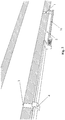
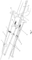
- the figure 1 illustrates a sound neutralizing device for a firearm in an embodiment of the invention.
- two closing flaps (10) are mounted transversely to the axis on the barrel of the weapon to temporarily close the barrel after the passage of a projectile and prevent the passage of combustion gases and the sound wave towards the muzzle of the cannon when a shot is fired.
- the actuation unit (1-5) has a first opening (1) made in the barrel upstream of the closing flaps (10) to form a gas outlet (1) and set the control mechanism (6-9 ) moving.
- the control mechanism (6-9) comprises two amplitude lever arms (8) mounted on pivots (7) to allow transverse movement of the two closing flaps (10) between an open position in which the flaps (10 ) ensure the passage of a projectile towards the muzzle of the barrel and a closed position preventing the passage of combustion gases and the sound wave after the passage of the projectile.
- the exhaust unit (11) has two exhaust pipes (11) disposed upstream of the closing flaps (10) to redirect and allow the combustion gases and the sound wave to escape from the barrel.
- the gas intake (1) made in the barrel at any point after the chamber sets in motion, by the pressure of the gases, a piston (2) for controlling the device arranged in a cylinder (16) and extended by a rod (2).
- the piston rod (2) is positioned in a direction generally parallel to the axis of the barrel defining the direction of the projectile.
- the control piston with the rod (2) is associated with a return spring arranged on the barrel. As the pressure drops, the piston rod (2) returns to its initial position thanks to the return spring.
- a clutch valve (4) is actuated to allow the coupling of the piston rod (2) to the transmission (5) which puts in motion the control mechanism (6).
- the clutch valve (4) and the transmission (5) are frictionally coupled.
- the control mechanism (6-9) is positioned upstream of the flaps (10).
- the control mechanism (6) operates the amplitude lever arms (8) which close the flaps (10), thus letting the gases escape through the pipes (11).
- the flaps (10) (and their seat) are placed transversely to the axis of the barrel and are of predetermined length and slightly offset between them along the axis of the barrel, so that in the closed position they partially overlap without colliding .
- each flap (10) has an opening adapted to receive the end of the amplitude lever arm (8) to transmit the pivoting movement of the amplitude lever (8) and actuate the flap (10) in one direction. transverse to the axis of the barrel.
- the elements (2,4,5,6) of the actuating mechanism are set in motion in a direction generally parallel to the axis of the barrel.
- control mechanism (6-9) comprises a guide ring (6) adapted to slide on the barrel and provided with an extension (5) of transmission cooperating with the piston rod (2) to transmit the movement to the lever arms (8).
- the piston rod (2) is coupled by the transmission extension (5) with the control (6) to set it in motion.
- the guide ring (6) further comprises two basic wedge-shaped parts arranged laterally to the axis of the barrel and having an angled edge surface (straight or curved) directed towards the flaps (10) adapted to enable the lever arms (8) to be pivoted on the pivots (7) to close the flaps (10).
- a first return spring is associated with the guide ring (6) so that it returns to its initial position, the pressure decreasing.
- a second return spring (9) is associated with each of the lever arms (8) so that the lever arms (8) and the flaps (10) return to their initial position, the pressure decreasing.
- the return springs (9) of the lever arms can be eliminated by adding a lateral guide (not shown) to the controls (6 and 15), which, while moving back, bring the arms back to their initial positions "
- the valve (4) acts as a clutch element (4) which is moved downwards to couple the piston rod (2) to the transmission (5).
- the clutch element (4) pushed down by the gas in the opening (3) when the ball passes blocks the element (4) of the rod (2) on the extension (5) of the ring (6) by transmitting the movement to it.
- parts 5 to 9 of the control mechanism are positioned downstream of the flaps (10).
- the figure 3B is similar to the figure 3A but the clutch valve and the transmission (5) are eliminated in this embodiment and there is a direct coupling of the piston rod to the control ring (6).
- the linkage of the control mechanism (6-9) is composed by two amplitude lever arms (8) mounted on pivots (7) and which, actuated by the control ring (6), close the two flaps ( 10).
- the piston (2) of the device placed in the cylinder (16) and extended by the rod (2) is directly linked to the control mechanism (6-9).
- parts 3, 4, 5 can be dispensed with.
- the second gas outlet (3), the clutch valve (4) and the transmission (5) are eliminated in this mode of embodiment, and there is a direct coupling of the piston rod (2) to the control ring (6).
- the piston (2) is connected to the control (6) by direct contact.
- the piston (2) and the control (6) are practically one piece.
- the piston (2) and the control (6) can be integrated and formed in one piece.
- the version in figures 4 and 5 is mainly intended for short-barreled weapons, but it is not an obligation.
- the linkage of the control mechanism is composed of two amplitude lever arms (8) mounted on pivots (7) and which, actuated by the control (6), close the flaps (10).
- the version of the Figure 3A is comparable to the version Figure 1 except that the closing mechanism is positioned after the flaps, this to shorten everything.
- the linkage is made up of two amplitude lever arms (8) mounted on pivots (7) and which, actuated by the control, close the flaps (10).
- the arms (8) are provided here to give an amplitude lever of 10 times, that is to say that the proportion of the arm between before and after the pivot are from 1 to 10, for a total length of 11 units .
- the amplitude, here 10 times, can be increased or decreased as desired.
- the version of the Figure 4 is intended mainly for short barrel weapons, but the advantage of the version of the Figure 1 with a second gas outlet (3) which pushes a clutch element (4) is that the piston (2) will already be in motion when the projectile passes and therefore that the coupling triggered by the clutch element ( 4) finds a part already in motion, which accelerates the shutter closing mechanism.
- the time which elapses between the percussion of the casing and the exit of the projectile from the barrel is of the order of 1.2 to 2.4 milliseconds.
- lever arms (8 and 12) are split, and the whole positioned either downstream of the flaps (10) as illustrated in figure 7 , either upstream of the flaps (not shown).
- the control mechanism (15) actuates the double arms of amplitude levers (8,12) which close the flaps (10), thus letting the gases escape through the pipes (11).
- the control mechanism (15) comprises a guide ring (15) which actuates two first amplitude lever arms (12) pivotally mounted on pivots (13) fixed to the barrel, and these two first lever arms.
- amplitude (12) are coupled to two second amplitude lever arms (8) pivotally mounted on pivots (7) fixed to the barrel.
- Each of the first two amplitude lever arms (12) actuates one of the associated second amplitude lever arms (8), each of the two second amplitude lever arms (8) being coupled to one of the closing flaps ( 10).
- control mechanism (15) spreads the amplitude lever arms (12) while the control mechanism (6) of the other embodiments brings the amplitude lever arms (8) closer.
- This variant of the figure 7 shortens the shutter closing system.
- the amplitude levers which have a ratio 1 to 10 are, in this variant, each replaced by 2 entangled levers, the longest with a ratio of 1 to 4 (therefore a total length of 5 units), and the second with a ratio of 1 to 2.5; we therefore find the value from 1 to 10 (4 x 2.5) for a total length of 5 units instead of 11 units.
- the entire mechanism can be protected by a cover for everyday use and avoid damage when used with a firearm, but it will depend on the weapon and its components. Since the cover is not essential for proper operation, it is not described in more detail.
- an expansion vessel with timer (22-27) is associated with the exhaust pipes (21) for the treatment of recovered gases and the inhibition of the sound wave.
- Other solutions are possible.
- the expansion tank 27 is coupled to the exhaust pipes (21) and has an internal axis (23) driven by the pressure of the gases to redirect these gases.
- the expansion tank 27 receives the gases carried by the recovery pipes (21) which enter the expansion tank 27 through the opening (22) formed on the axis (23) once it has been pushed to the end of the stroke and thus having closed the openings (24).
- a pressure relief valve (25) is present (but could be replaced by small holes). The pressure going down, the axis returns to its initial position thanks to the return spring 26 and the gases are evacuated through the vents (24).
- the final aim of the device achieved by the invention described here is the inhibition of the sound wave produced by the firing of the ammunition (gunshot).
- This shutter intended for the inhibition of the sound wave produced by the firing of the ammunition prevents the exit of the gases of combustion and sound waves by the mouth of the barrel by deflecting them towards a zone of treatment adequate, while leaving intact the prerogatives specific to ammunition (speed, precision).
- the shutter valve (a shutter or double shutter) will close the barrel after the passage of the projectile; moving at the same speed as the projectile the distance traveled by the latter before the complete closure of the barrel will be equal to the internal diameter of the barrel - it will be half when using a double flap (DV); for a 7mm round the distance will therefore be 7mm (DV: 3.5mm.); for a 18.4 mm shot 12 caliber, it will be 18.4mm (DV: 9.2mm).
- the volume of gas that the valve thus allows to pass before closing will therefore be 2.69 cm3 (DV: 1.35 cm3) for a 7mm ammunition and 4.89 cm3 (DV: 2.45 cm3) for a 12 caliber rifle.
- the reduction in noise intensity can be of the order of 50 to 70 dbA, or even more, in the case of a long gun.
- the residual noise is that caused by the projectile whipping the air.
- the combustion gases are recovered by making a hole in the barrel. These gases will set in motion a control piston whose rod (2) will be used to actuate the closing mechanism, with or without the intervention of a transmission valve (4) actuated by the gas recovered after the passage of the projectile.
- the closing mechanism consists of lever arms (8) actuated by a part (5) whose shape can be variable.
- the projectile Once the projectile has passed the shutters, they close very quickly and the gases are directed to one or two exhaust pipes leading to an expansion tank with timer.
- the gases conveyed by the recovery pipes (21) enter the expansion tank through the opening (22) formed on the axis (23) once it has been pushed to the end of its travel and thus closed. the openings (24).
- a pressure relief valve (25) is present (but could be replaced by small holes). The pressure decreasing, the axis returns to its initial position thanks to the spring (26) and the gases are evacuated through the gills.
- the ring (6) should in reality only move between 0.6 and 2 mm, depending on the sizes and the chosen amplitude of the levers.
- this expansion vessel can have any shape and can be made from any material, solid or elastic; it can be applied anywhere on the weapon (for example laterally on the barrel or below);
- the shutter device will be actuated by linkage.
- the setting in motion of the whole device will, for example, be controlled by a piston of about 4-5 mm in diameter with a rod (2) at the end, located in a tube and driven by the recovery of gases in this way: 2 holes about 2mm in diameter after the explosion chamber communicating with the tube in which is the piston; if necessary, the tube can be at the start with a larger diameter than what is necessary, and then reduced at the level of the piston: this has the effect of increasing the pressure of the gases and thus the speed of movement of the piston (2 ).
- the rod (2) moved by the piston will actuate the valve and the pump, with a return to the initial position by return spring.
- the piston will be of relatively strong weight to ensure the kinetic inertia; on the other hand the other moving parts will together have a weight of the total order of less than 10 grams.
- the length of the amplitude levers (8) (12) varies according to size and the desired amplitude effect. If the latter is 10 times then for a 7 mm caliber ammunition (including each flap will move 4 mm), the length of the amplitude levers will be approximately 2 cm after the pivot, the control moving by 0.4mm. For a 12 gauge ammunition (approximately 2 cm in diameter) the length of the amplitude levers will be approximately 5 cm after the pivot.
- the operating speed (of the order of milliseconds) is essential.
- the piston will therefore already be in motion when the passage of the projectile triggers the device, to avoid the latency of the inertia of setting in motion.
- the piston according to its weight, its positioning relative to the chamber of the weapon, and the caliber of the latter will have a speed which can be lower, equal, or even higher than that of the projectile (this does not have much importance). As it will not have much importance a variation of the speed of the ammunition because it results in a difference in micrometric displacement, and that in addition the piston receives proportionally always the same force.
- the arms (8,12) are provided here to give an amplitude lever of 10 times, that is to say that the proportion of the arm between before and after the pivot are from 1 to 10, for a length total of 11 units.
- the “compact” version of the figure 7 is used to reduce this distance.
- the first battery of levers (12) has a proportion of 1 to 2.5 and the final battery (8) of 1 to 4. In this example the total length of 11 units is therefore reduced to 5 while keeping an amplitude of 10 times.
- the amplitude here 10 times, can be increased or decreased as desired.
- the force generated by the recovery of gas being much greater than the needs of the device.
- the calibers of weapons in internal diameter vary from 5.5 mm to 20 mm. Taking into account the piston speed, the amplitude of the lever and the diameter of the on can easily calculate the volume of gas allowed to escape from the muzzle before the shutters are closed.
- the particular characteristics and advantages of the invention are in particular that, provided with the device of the invention for neutralizing the sound and muzzle fire of a firearm, no annoying sound comes out of the firearm and that the projectiles keep intact all their prerogatives (speed, precision) without producing any noise by the shock wave.
- the residual noise is that caused by the projectile whipping the air.
- the device of the invention is very light and inexpensive.
- All parts, their shape and their positions can vary endlessly.
- the recovery or exhaust pipes can be reduced to one and not necessarily tubular, the expansion tank be of a different shape, the control 6 represented by a complete circular ring could be in an arc of a circle, etc.
Landscapes
- Engineering & Computer Science (AREA)
- General Engineering & Computer Science (AREA)
- Exhaust Silencers (AREA)
- Toys (AREA)
- Organic Low-Molecular-Weight Compounds And Preparation Thereof (AREA)
- Headphones And Earphones (AREA)
- Aiming, Guidance, Guns With A Light Source, Armor, Camouflage, And Targets (AREA)
Priority Applications (5)
| Application Number | Priority Date | Filing Date | Title |
|---|---|---|---|
| RS20201107A RS60810B1 (sr) | 2016-07-18 | 2017-07-14 | Prigušivač za vatreno oružje |
| HRP20201356TT HRP20201356T1 (hr) | 2016-07-18 | 2017-07-14 | Prigušivač za vatreno oružje |
| SI201730411T SI3485216T1 (sl) | 2016-07-18 | 2017-07-14 | Dušilna naprava zvoka za strelno orožje |
| PL17746003T PL3485216T3 (pl) | 2016-07-18 | 2017-07-14 | Urządzenie neutralizujące dźwięk do broni palnej |
| SM20200491T SMT202000491T1 (it) | 2016-07-18 | 2017-07-14 | Dispositivo silenziatore per arma da fuoco |
Applications Claiming Priority (2)
| Application Number | Priority Date | Filing Date | Title |
|---|---|---|---|
| LU93152A LU93152B1 (fr) | 2016-07-18 | 2016-07-18 | Dispositif neutraliseur de son pour arme à feu |
| PCT/EP2017/067873 WO2018015301A1 (fr) | 2016-07-18 | 2017-07-14 | Dispositif neutralisateur de son pour arme à feu |
Publications (2)
| Publication Number | Publication Date |
|---|---|
| EP3485216A1 EP3485216A1 (fr) | 2019-05-22 |
| EP3485216B1 true EP3485216B1 (fr) | 2020-06-17 |
Family
ID=56571351
Family Applications (1)
| Application Number | Title | Priority Date | Filing Date |
|---|---|---|---|
| EP17746003.7A Active EP3485216B1 (fr) | 2016-07-18 | 2017-07-14 | Dispositif neutralisateur de son pour arme à feu |
Country Status (22)
| Country | Link |
|---|---|
| US (1) | US10718587B2 (sr) |
| EP (1) | EP3485216B1 (sr) |
| JP (1) | JP2019521309A (sr) |
| CN (1) | CN109690229A (sr) |
| BR (1) | BR112019001123A2 (sr) |
| CA (1) | CA3031229A1 (sr) |
| CY (1) | CY1123327T1 (sr) |
| DK (1) | DK3485216T3 (sr) |
| EA (1) | EA037134B1 (sr) |
| ES (1) | ES2820282T3 (sr) |
| HR (1) | HRP20201356T1 (sr) |
| HU (1) | HUE050916T2 (sr) |
| IL (1) | IL264286A (sr) |
| LT (1) | LT3485216T (sr) |
| LU (1) | LU93152B1 (sr) |
| MX (1) | MX2019000710A (sr) |
| PL (1) | PL3485216T3 (sr) |
| PT (1) | PT3485216T (sr) |
| RS (1) | RS60810B1 (sr) |
| SI (1) | SI3485216T1 (sr) |
| SM (1) | SMT202000491T1 (sr) |
| WO (1) | WO2018015301A1 (sr) |
Families Citing this family (3)
| Publication number | Priority date | Publication date | Assignee | Title |
|---|---|---|---|---|
| US11927410B2 (en) * | 2021-09-27 | 2024-03-12 | Jacob KUNSKY | Firearm suppressor with remote chamber |
| US11976896B2 (en) * | 2022-02-25 | 2024-05-07 | True Velocity Ip Holdings, Llc | Firearm muzzle brake with gas-actuated valve |
| CN115950301B (zh) * | 2022-12-09 | 2025-05-06 | 西安昆仑工业(集团)有限责任公司 | 一种水下炮口密封装置及使用方法 |
Family Cites Families (20)
| Publication number | Priority date | Publication date | Assignee | Title |
|---|---|---|---|---|
| DE150359C (sr) * | ||||
| US652742A (en) * | 1897-11-17 | 1900-07-03 | Max Bernstein | Device for preventing reports of guns. |
| US832695A (en) * | 1905-09-01 | 1906-10-09 | Johan Olsen Nygaard | Attachment to the barrels of firearms. |
| CH34973A (fr) * | 1905-09-02 | 1906-06-30 | Nygaards Gevaerkompagni As | Arme à feu perfectionnée |
| US984750A (en) * | 1910-02-01 | 1911-02-21 | Harry Craven | Gun-silencer. |
| US1130609A (en) * | 1913-12-15 | 1915-03-02 | Seth T Jones | Muffler for shotguns. |
| BE347810A (sr) * | 1927-04-27 | |||
| BE345878A (sr) * | 1927-09-01 | 1900-01-01 | ||
| US1773443A (en) * | 1927-10-27 | 1930-08-19 | Wilman Zygmunt | Manufacture of silencers or exhaust tanks for machine guns and other automatic arms |
| DE2238834A1 (de) * | 1972-08-07 | 1974-02-14 | Ernst Kitzmann | Schalldaempfer fuer waffen verschiedener art |
| US4939977A (en) * | 1989-06-07 | 1990-07-10 | Stroup Larry J | Gun silencer and muzzle protector |
| FR2719937B1 (fr) | 1994-05-16 | 1996-08-02 | Bernard Louvat | Dispositif modérateur de son. |
| US5746018A (en) * | 1997-05-19 | 1998-05-05 | The United States Of America As Represented By The Secretary Of The Navy | Muzzle brake for an underwater gun |
| US7516690B2 (en) * | 2006-12-22 | 2009-04-14 | Mcclellan W Thomas | Firearm suppressor, mounting system and mounting method |
| WO2011035111A1 (en) | 2009-09-18 | 2011-03-24 | Silencerco, Llc | Firearm sound suppressor |
| CH702214B1 (de) * | 2009-11-13 | 2018-02-15 | Sphinx Systems Ag | Schalldämpfer für halb- und vollautomatische Feuerwaffen, mit einer Blockiervorrichtung für einen beweglichen Anschluss. |
| US8397862B2 (en) * | 2010-08-04 | 2013-03-19 | Ronnie Alexander Shand | Sound and flash suppressor for firearms |
| TW201233887A (en) * | 2010-10-08 | 2012-08-16 | Pinnacle Engines Inc | Integrated muffler and emissions control for engine exhaust |
| CN102735099A (zh) * | 2012-06-14 | 2012-10-17 | 浙江新华体育器材制造有限公司 | 一种带有消音器的射击枪械 |
| EP2867607B1 (de) | 2012-06-28 | 2016-08-10 | Steindl, Andreas | Schalldämpfer für eine handfeuerwaffe |
-
2016
- 2016-07-18 LU LU93152A patent/LU93152B1/fr active IP Right Grant
-
2017
- 2017-07-14 US US16/318,929 patent/US10718587B2/en not_active Expired - Fee Related
- 2017-07-14 HU HUE17746003A patent/HUE050916T2/hu unknown
- 2017-07-14 PT PT177460037T patent/PT3485216T/pt unknown
- 2017-07-14 DK DK17746003.7T patent/DK3485216T3/da active
- 2017-07-14 MX MX2019000710A patent/MX2019000710A/es unknown
- 2017-07-14 EP EP17746003.7A patent/EP3485216B1/fr active Active
- 2017-07-14 ES ES17746003T patent/ES2820282T3/es active Active
- 2017-07-14 RS RS20201107A patent/RS60810B1/sr unknown
- 2017-07-14 CA CA3031229A patent/CA3031229A1/en not_active Abandoned
- 2017-07-14 LT LTEP17746003.7T patent/LT3485216T/lt unknown
- 2017-07-14 EA EA201900035A patent/EA037134B1/ru not_active IP Right Cessation
- 2017-07-14 PL PL17746003T patent/PL3485216T3/pl unknown
- 2017-07-14 JP JP2019503352A patent/JP2019521309A/ja active Pending
- 2017-07-14 BR BR112019001123-4A patent/BR112019001123A2/pt not_active Application Discontinuation
- 2017-07-14 SM SM20200491T patent/SMT202000491T1/it unknown
- 2017-07-14 HR HRP20201356TT patent/HRP20201356T1/hr unknown
- 2017-07-14 SI SI201730411T patent/SI3485216T1/sl unknown
- 2017-07-14 WO PCT/EP2017/067873 patent/WO2018015301A1/fr not_active Ceased
- 2017-07-14 CN CN201780049897.9A patent/CN109690229A/zh active Pending
-
2019
- 2019-01-16 IL IL264286A patent/IL264286A/en unknown
-
2020
- 2020-09-07 CY CY20201100838T patent/CY1123327T1/el unknown
Non-Patent Citations (1)
| Title |
|---|
| None * |
Also Published As
| Publication number | Publication date |
|---|---|
| CA3031229A1 (en) | 2018-01-25 |
| RS60810B1 (sr) | 2020-10-30 |
| US20190293377A1 (en) | 2019-09-26 |
| JP2019521309A (ja) | 2019-07-25 |
| US10718587B2 (en) | 2020-07-21 |
| MX2019000710A (es) | 2019-10-14 |
| CN109690229A (zh) | 2019-04-26 |
| EP3485216A1 (fr) | 2019-05-22 |
| PL3485216T3 (pl) | 2020-12-28 |
| CY1123327T1 (el) | 2021-12-31 |
| DK3485216T3 (da) | 2020-09-14 |
| PT3485216T (pt) | 2020-09-21 |
| BR112019001123A2 (pt) | 2019-04-30 |
| ES2820282T3 (es) | 2021-04-20 |
| SMT202000491T1 (it) | 2021-01-05 |
| EA037134B1 (ru) | 2021-02-10 |
| HUE050916T2 (hu) | 2021-01-28 |
| LT3485216T (lt) | 2020-11-10 |
| EA201900035A1 (ru) | 2019-07-31 |
| LU93152B1 (fr) | 2018-03-05 |
| WO2018015301A1 (fr) | 2018-01-25 |
| HRP20201356T1 (hr) | 2020-11-27 |
| IL264286A (en) | 2019-02-28 |
| SI3485216T1 (sl) | 2020-10-30 |
Similar Documents
| Publication | Publication Date | Title |
|---|---|---|
| BE1016266A5 (fr) | Dispositif d'attenuation du rebond pour des armes a feu automatiques. | |
| EP0324688B1 (fr) | Arme d'épaule à usage de lance-roquette | |
| CH699667A2 (fr) | Nouveau mecanisme de retard d'ouverture pour arme automatique. | |
| LU93152B1 (fr) | Dispositif neutraliseur de son pour arme à feu | |
| EP0766807B1 (fr) | Systeme d'arme a feu individuelle | |
| EP3504501B1 (fr) | Dispositif neutralisateur de son pour arme à feu | |
| WO1993013382A1 (fr) | Tube douille pour grenade a fusil pouvant retenir les fragments de la balle | |
| EP2653821B1 (fr) | Dispositif réducteur de bruit pour arme à feu | |
| EP0030051B1 (fr) | Grenade à fusil | |
| EP0884553B1 (fr) | Ensemble de propulsion pour projectile limitant l'effort de recul | |
| EP0027418B1 (fr) | Dispositif pour permettre le tir d'un projectile sans éjection de gaz vers l'arrière, ni recul, au moyen d'un tube de lancement ouvert à ses deux extrémités | |
| FR2695717A1 (fr) | Sabot pour projectile pour accélérateur par effet de statoréacteur et projectile équipé d'un tel sabot. | |
| FR2937123A1 (fr) | Munition de controle des foules a effet non letal | |
| FR3061768A1 (fr) | Dispositif d'evacuation de douilles | |
| FR2725268A1 (fr) | Lanceur de projectile, a canon consommable | |
| HK40007056A (en) | Silencer for firearm | |
| HK40007056B (en) | Silencer for firearm | |
| BE395618A (sr) | ||
| CH524124A (fr) | Arme à feu munie d'un dispositif destiné à en réduire le recul | |
| FR2818369A1 (fr) | Arme d'epaule destinee a tirer des munitions a forte impulsion | |
| FR2835047A1 (fr) | Ensemble de conversion d'entrainement pour armes automatiques ou semi-automatiques a mouvement amplificateur d'inertie | |
| BE740483A (sr) | ||
| FR2627853A1 (fr) | Lance-grenades | |
| HK40003225A (en) | Silencer device for firearm | |
| HK40003225B (en) | Silencer device for firearm |
Legal Events
| Date | Code | Title | Description |
|---|---|---|---|
| STAA | Information on the status of an ep patent application or granted ep patent |
Free format text: STATUS: UNKNOWN |
|
| STAA | Information on the status of an ep patent application or granted ep patent |
Free format text: STATUS: THE INTERNATIONAL PUBLICATION HAS BEEN MADE |
|
| PUAI | Public reference made under article 153(3) epc to a published international application that has entered the european phase |
Free format text: ORIGINAL CODE: 0009012 |
|
| STAA | Information on the status of an ep patent application or granted ep patent |
Free format text: STATUS: REQUEST FOR EXAMINATION WAS MADE |
|
| 17P | Request for examination filed |
Effective date: 20190212 |
|
| AK | Designated contracting states |
Kind code of ref document: A1 Designated state(s): AL AT BE BG CH CY CZ DE DK EE ES FI FR GB GR HR HU IE IS IT LI LT LU LV MC MK MT NL NO PL PT RO RS SE SI SK SM TR |
|
| AX | Request for extension of the european patent |
Extension state: BA ME |
|
| DAV | Request for validation of the european patent (deleted) | ||
| DAX | Request for extension of the european patent (deleted) | ||
| GRAP | Despatch of communication of intention to grant a patent |
Free format text: ORIGINAL CODE: EPIDOSNIGR1 |
|
| STAA | Information on the status of an ep patent application or granted ep patent |
Free format text: STATUS: GRANT OF PATENT IS INTENDED |
|
| INTG | Intention to grant announced |
Effective date: 20200108 |
|
| GRAS | Grant fee paid |
Free format text: ORIGINAL CODE: EPIDOSNIGR3 |
|
| GRAA | (expected) grant |
Free format text: ORIGINAL CODE: 0009210 |
|
| STAA | Information on the status of an ep patent application or granted ep patent |
Free format text: STATUS: THE PATENT HAS BEEN GRANTED |
|
| REG | Reference to a national code |
Ref country code: HK Ref legal event code: DE Ref document number: 40007056 Country of ref document: HK |
|
| AK | Designated contracting states |
Kind code of ref document: B1 Designated state(s): AL AT BE BG CH CY CZ DE DK EE ES FI FR GB GR HR HU IE IS IT LI LT LU LV MC MK MT NL NO PL PT RO RS SE SI SK SM TR |
|
| REG | Reference to a national code |
Ref country code: GB Ref legal event code: FG4D Free format text: NOT ENGLISH |
|
| REG | Reference to a national code |
Ref country code: CH Ref legal event code: EP |
|
| REG | Reference to a national code |
Ref country code: DE Ref legal event code: R096 Ref document number: 602017018384 Country of ref document: DE |
|
| REG | Reference to a national code |
Ref country code: IE Ref legal event code: FG4D Free format text: LANGUAGE OF EP DOCUMENT: FRENCH |
|
| REG | Reference to a national code |
Ref country code: AT Ref legal event code: REF Ref document number: 1281822 Country of ref document: AT Kind code of ref document: T Effective date: 20200715 |
|
| REG | Reference to a national code |
Ref country code: HR Ref legal event code: TUEP Ref document number: P20201356T Country of ref document: HR |
|
| REG | Reference to a national code |
Ref country code: NL Ref legal event code: FP |
|
| REG | Reference to a national code |
Ref country code: DK Ref legal event code: T3 Effective date: 20200909 |
|
| REG | Reference to a national code |
Ref country code: CH Ref legal event code: NV Representative=s name: DENNEMEYER AG, CH |
|
| REG | Reference to a national code |
Ref country code: FI Ref legal event code: FGE |
|
| REG | Reference to a national code |
Ref country code: PT Ref legal event code: SC4A Ref document number: 3485216 Country of ref document: PT Date of ref document: 20200921 Kind code of ref document: T Free format text: AVAILABILITY OF NATIONAL TRANSLATION Effective date: 20200914 |
|
| REG | Reference to a national code |
Ref country code: NO Ref legal event code: T2 Effective date: 20200617 |
|
| REG | Reference to a national code |
Ref country code: SE Ref legal event code: TRGR |
|
| PGFP | Annual fee paid to national office [announced via postgrant information from national office to epo] |
Ref country code: NL Payment date: 20200727 Year of fee payment: 4 |
|
| REG | Reference to a national code |
Ref country code: GR Ref legal event code: EP Ref document number: 20200402582 Country of ref document: GR Effective date: 20201014 |
|
| PGFP | Annual fee paid to national office [announced via postgrant information from national office to epo] |
Ref country code: ES Payment date: 20200922 Year of fee payment: 4 Ref country code: GR Payment date: 20200922 Year of fee payment: 4 Ref country code: TR Payment date: 20200908 Year of fee payment: 4 Ref country code: IE Payment date: 20200727 Year of fee payment: 4 Ref country code: RO Payment date: 20200710 Year of fee payment: 4 Ref country code: LT Payment date: 20200804 Year of fee payment: 4 Ref country code: MC Payment date: 20200723 Year of fee payment: 4 |
|
| REG | Reference to a national code |
Ref country code: HR Ref legal event code: ODRP Ref document number: P20201356T Country of ref document: HR Payment date: 20200901 Year of fee payment: 4 |
|
| REG | Reference to a national code |
Ref country code: EE Ref legal event code: FG4A Ref document number: E019823 Country of ref document: EE Effective date: 20200908 |
|
| REG | Reference to a national code |
Ref country code: HR Ref legal event code: T1PR Ref document number: P20201356 Country of ref document: HR |
|
| PGFP | Annual fee paid to national office [announced via postgrant information from national office to epo] |
Ref country code: SI Payment date: 20200709 Year of fee payment: 4 Ref country code: MK Payment date: 20200909 Year of fee payment: 4 Ref country code: RS Payment date: 20200713 Year of fee payment: 4 Ref country code: LV Payment date: 20200717 Year of fee payment: 4 |
|
| REG | Reference to a national code |
Ref country code: SK Ref legal event code: T3 Ref document number: E 35221 Country of ref document: SK |
|
| PGFP | Annual fee paid to national office [announced via postgrant information from national office to epo] |
Ref country code: HR Payment date: 20200901 Year of fee payment: 4 Ref country code: MT Payment date: 20200915 Year of fee payment: 4 |
|
| REG | Reference to a national code |
Ref country code: HU Ref legal event code: AG4A Ref document number: E050916 Country of ref document: HU |
|
| PGFP | Annual fee paid to national office [announced via postgrant information from national office to epo] |
Ref country code: HU Payment date: 20200905 Year of fee payment: 4 Ref country code: CY Payment date: 20200727 Year of fee payment: 4 Ref country code: SM Payment date: 20201119 Year of fee payment: 4 Ref country code: BG Payment date: 20200728 Year of fee payment: 4 |
|
| PGFP | Annual fee paid to national office [announced via postgrant information from national office to epo] |
Ref country code: SK Payment date: 20200713 Year of fee payment: 4 Ref country code: PL Payment date: 20200811 Year of fee payment: 4 |
|
| REG | Reference to a national code |
Ref country code: DE Ref legal event code: R097 Ref document number: 602017018384 Country of ref document: DE |
|
| REG | Reference to a national code |
Ref country code: ES Ref legal event code: FG2A Ref document number: 2820282 Country of ref document: ES Kind code of ref document: T3 Effective date: 20210420 |
|
| PLBE | No opposition filed within time limit |
Free format text: ORIGINAL CODE: 0009261 |
|
| STAA | Information on the status of an ep patent application or granted ep patent |
Free format text: STATUS: NO OPPOSITION FILED WITHIN TIME LIMIT |
|
| 26N | No opposition filed |
Effective date: 20210318 |
|
| PGFP | Annual fee paid to national office [announced via postgrant information from national office to epo] |
Ref country code: AL Payment date: 20201125 Year of fee payment: 4 |
|
| REG | Reference to a national code |
Ref country code: HR Ref legal event code: PBON Ref document number: P20201356 Country of ref document: HR Effective date: 20210714 |
|
| REG | Reference to a national code |
Ref country code: NL Ref legal event code: MM Effective date: 20210801 |
|
| PG25 | Lapsed in a contracting state [announced via postgrant information from national office to epo] |
Ref country code: MC Free format text: LAPSE BECAUSE OF NON-PAYMENT OF DUE FEES Effective date: 20210802 |
|
| PGFP | Annual fee paid to national office [announced via postgrant information from national office to epo] |
Ref country code: LU Payment date: 20220127 Year of fee payment: 5 |
|
| REG | Reference to a national code |
Ref country code: SK Ref legal event code: MM4A Ref document number: E 35221 Country of ref document: SK Effective date: 20210714 |
|
| PG25 | Lapsed in a contracting state [announced via postgrant information from national office to epo] |
Ref country code: RS Free format text: LAPSE BECAUSE OF NON-PAYMENT OF DUE FEES Effective date: 20210714 Ref country code: HU Free format text: LAPSE BECAUSE OF NON-PAYMENT OF DUE FEES Effective date: 20210715 Ref country code: BG Free format text: LAPSE BECAUSE OF NON-PAYMENT OF DUE FEES Effective date: 20220131 |
|
| PGFP | Annual fee paid to national office [announced via postgrant information from national office to epo] |
Ref country code: GB Payment date: 20220127 Year of fee payment: 5 Ref country code: FI Payment date: 20220127 Year of fee payment: 5 Ref country code: DK Payment date: 20220128 Year of fee payment: 5 Ref country code: DE Payment date: 20220127 Year of fee payment: 5 Ref country code: CH Payment date: 20220127 Year of fee payment: 5 |
|
| REG | Reference to a national code |
Ref country code: AT Ref legal event code: UEP Ref document number: 1281822 Country of ref document: AT Kind code of ref document: T Effective date: 20200617 |
|
| REG | Reference to a national code |
Ref country code: LT Ref legal event code: MM4D Effective date: 20210714 |
|
| PG25 | Lapsed in a contracting state [announced via postgrant information from national office to epo] |
Ref country code: SK Free format text: LAPSE BECAUSE OF NON-PAYMENT OF DUE FEES Effective date: 20210714 Ref country code: RO Free format text: LAPSE BECAUSE OF NON-PAYMENT OF DUE FEES Effective date: 20210714 Ref country code: NL Free format text: LAPSE BECAUSE OF NON-PAYMENT OF DUE FEES Effective date: 20210801 Ref country code: LV Free format text: LAPSE BECAUSE OF NON-PAYMENT OF DUE FEES Effective date: 20210714 Ref country code: HR Free format text: LAPSE BECAUSE OF NON-PAYMENT OF DUE FEES Effective date: 20210714 Ref country code: GR Free format text: LAPSE BECAUSE OF NON-PAYMENT OF DUE FEES Effective date: 20220207 Ref country code: CY Free format text: LAPSE BECAUSE OF NON-PAYMENT OF DUE FEES Effective date: 20210714 Ref country code: SM Free format text: LAPSE BECAUSE OF NON-PAYMENT OF DUE FEES Effective date: 20220210 |
|
| PGFP | Annual fee paid to national office [announced via postgrant information from national office to epo] |
Ref country code: IS Payment date: 20220127 Year of fee payment: 5 Ref country code: SE Payment date: 20220128 Year of fee payment: 5 Ref country code: PT Payment date: 20220208 Year of fee payment: 5 Ref country code: NO Payment date: 20220128 Year of fee payment: 5 Ref country code: IT Payment date: 20220128 Year of fee payment: 5 Ref country code: FR Payment date: 20220121 Year of fee payment: 5 Ref country code: EE Payment date: 20220127 Year of fee payment: 5 Ref country code: CZ Payment date: 20220113 Year of fee payment: 5 Ref country code: BE Payment date: 20220127 Year of fee payment: 5 |
|
| PG25 | Lapsed in a contracting state [announced via postgrant information from national office to epo] |
Ref country code: LT Free format text: LAPSE BECAUSE OF NON-PAYMENT OF DUE FEES Effective date: 20210714 Ref country code: IE Free format text: LAPSE BECAUSE OF NON-PAYMENT OF DUE FEES Effective date: 20210714 |
|
| REG | Reference to a national code |
Ref country code: ES Ref legal event code: FD2A Effective date: 20220826 |
|
| PG25 | Lapsed in a contracting state [announced via postgrant information from national office to epo] |
Ref country code: ES Free format text: LAPSE BECAUSE OF NON-PAYMENT OF DUE FEES Effective date: 20210715 |
|
| REG | Reference to a national code |
Ref country code: DE Ref legal event code: R119 Ref document number: 602017018384 Country of ref document: DE |
|
| REG | Reference to a national code |
Ref country code: EE Ref legal event code: MM4A Ref document number: E019823 Country of ref document: EE Effective date: 20220731 |
|
| REG | Reference to a national code |
Ref country code: NO Ref legal event code: MMEP Ref country code: DK Ref legal event code: EBP Effective date: 20220731 |
|
| REG | Reference to a national code |
Ref country code: CH Ref legal event code: PL Ref country code: SE Ref legal event code: EUG |
|
| GBPC | Gb: european patent ceased through non-payment of renewal fee |
Effective date: 20220714 |
|
| REG | Reference to a national code |
Ref country code: BE Ref legal event code: MM Effective date: 20220731 |
|
| PG25 | Lapsed in a contracting state [announced via postgrant information from national office to epo] |
Ref country code: SE Free format text: LAPSE BECAUSE OF NON-PAYMENT OF DUE FEES Effective date: 20220715 Ref country code: PT Free format text: LAPSE BECAUSE OF NON-PAYMENT OF DUE FEES Effective date: 20230116 Ref country code: NO Free format text: LAPSE BECAUSE OF NON-PAYMENT OF DUE FEES Effective date: 20220731 Ref country code: LU Free format text: LAPSE BECAUSE OF NON-PAYMENT OF DUE FEES Effective date: 20220714 Ref country code: LI Free format text: LAPSE BECAUSE OF NON-PAYMENT OF DUE FEES Effective date: 20220731 Ref country code: FR Free format text: LAPSE BECAUSE OF NON-PAYMENT OF DUE FEES Effective date: 20220731 Ref country code: FI Free format text: LAPSE BECAUSE OF NON-PAYMENT OF DUE FEES Effective date: 20220714 Ref country code: CZ Free format text: LAPSE BECAUSE OF NON-PAYMENT OF DUE FEES Effective date: 20220714 Ref country code: CH Free format text: LAPSE BECAUSE OF NON-PAYMENT OF DUE FEES Effective date: 20220731 |
|
| PG25 | Lapsed in a contracting state [announced via postgrant information from national office to epo] |
Ref country code: PL Free format text: LAPSE BECAUSE OF NON-PAYMENT OF DUE FEES Effective date: 20210714 Ref country code: GB Free format text: LAPSE BECAUSE OF NON-PAYMENT OF DUE FEES Effective date: 20220714 Ref country code: EE Free format text: LAPSE BECAUSE OF NON-PAYMENT OF DUE FEES Effective date: 20220731 Ref country code: DE Free format text: LAPSE BECAUSE OF NON-PAYMENT OF DUE FEES Effective date: 20230201 Ref country code: BE Free format text: LAPSE BECAUSE OF NON-PAYMENT OF DUE FEES Effective date: 20220731 |
|
| PG25 | Lapsed in a contracting state [announced via postgrant information from national office to epo] |
Ref country code: IT Free format text: LAPSE BECAUSE OF NON-PAYMENT OF DUE FEES Effective date: 20220714 Ref country code: DK Free format text: LAPSE BECAUSE OF NON-PAYMENT OF DUE FEES Effective date: 20220731 |
|
| REG | Reference to a national code |
Ref country code: AT Ref legal event code: MM01 Ref document number: 1281822 Country of ref document: AT Kind code of ref document: T Effective date: 20220714 |
|
| PG25 | Lapsed in a contracting state [announced via postgrant information from national office to epo] |
Ref country code: AT Free format text: LAPSE BECAUSE OF NON-PAYMENT OF DUE FEES Effective date: 20220714 |
|
| PG25 | Lapsed in a contracting state [announced via postgrant information from national office to epo] |
Ref country code: MT Free format text: LAPSE BECAUSE OF FAILURE TO SUBMIT A TRANSLATION OF THE DESCRIPTION OR TO PAY THE FEE WITHIN THE PRESCRIBED TIME-LIMIT Effective date: 20200617 |
|
| PG25 | Lapsed in a contracting state [announced via postgrant information from national office to epo] |
Ref country code: IS Free format text: LAPSE BECAUSE OF NON-PAYMENT OF DUE FEES Effective date: 20220204 |