EP3484657B1 - Energiespeichervorrichtung und verfahren zur herstellung solch einer energiespeichervorrichtung - Google Patents
Energiespeichervorrichtung und verfahren zur herstellung solch einer energiespeichervorrichtung Download PDFInfo
- Publication number
- EP3484657B1 EP3484657B1 EP17735542.7A EP17735542A EP3484657B1 EP 3484657 B1 EP3484657 B1 EP 3484657B1 EP 17735542 A EP17735542 A EP 17735542A EP 3484657 B1 EP3484657 B1 EP 3484657B1
- Authority
- EP
- European Patent Office
- Prior art keywords
- welded part
- container
- energy storage
- storage device
- lid body
- Prior art date
- Legal status (The legal status is an assumption and is not a legal conclusion. Google has not performed a legal analysis and makes no representation as to the accuracy of the status listed.)
- Active
Links
Images




Classifications
-
- B—PERFORMING OPERATIONS; TRANSPORTING
- B23—MACHINE TOOLS; METAL-WORKING NOT OTHERWISE PROVIDED FOR
- B23K—SOLDERING OR UNSOLDERING; WELDING; CLADDING OR PLATING BY SOLDERING OR WELDING; CUTTING BY APPLYING HEAT LOCALLY, e.g. FLAME CUTTING; WORKING BY LASER BEAM
- B23K26/00—Working by laser beam, e.g. welding, cutting or boring
- B23K26/20—Bonding
- B23K26/21—Bonding by welding
-
- B—PERFORMING OPERATIONS; TRANSPORTING
- B23—MACHINE TOOLS; METAL-WORKING NOT OTHERWISE PROVIDED FOR
- B23K—SOLDERING OR UNSOLDERING; WELDING; CLADDING OR PLATING BY SOLDERING OR WELDING; CUTTING BY APPLYING HEAT LOCALLY, e.g. FLAME CUTTING; WORKING BY LASER BEAM
- B23K26/00—Working by laser beam, e.g. welding, cutting or boring
- B23K26/08—Devices involving relative movement between laser beam and workpiece
- B23K26/082—Scanning systems, i.e. devices involving movement of the laser beam relative to the laser head
-
- B—PERFORMING OPERATIONS; TRANSPORTING
- B23—MACHINE TOOLS; METAL-WORKING NOT OTHERWISE PROVIDED FOR
- B23K—SOLDERING OR UNSOLDERING; WELDING; CLADDING OR PLATING BY SOLDERING OR WELDING; CUTTING BY APPLYING HEAT LOCALLY, e.g. FLAME CUTTING; WORKING BY LASER BEAM
- B23K26/00—Working by laser beam, e.g. welding, cutting or boring
- B23K26/20—Bonding
- B23K26/206—Laser sealing
-
- B—PERFORMING OPERATIONS; TRANSPORTING
- B23—MACHINE TOOLS; METAL-WORKING NOT OTHERWISE PROVIDED FOR
- B23K—SOLDERING OR UNSOLDERING; WELDING; CLADDING OR PLATING BY SOLDERING OR WELDING; CUTTING BY APPLYING HEAT LOCALLY, e.g. FLAME CUTTING; WORKING BY LASER BEAM
- B23K26/00—Working by laser beam, e.g. welding, cutting or boring
- B23K26/20—Bonding
- B23K26/21—Bonding by welding
- B23K26/24—Seam welding
- B23K26/28—Seam welding of curved planar seams
-
- H—ELECTRICITY
- H01—ELECTRIC ELEMENTS
- H01M—PROCESSES OR MEANS, e.g. BATTERIES, FOR THE DIRECT CONVERSION OF CHEMICAL ENERGY INTO ELECTRICAL ENERGY
- H01M50/00—Constructional details or processes of manufacture of the non-active parts of electrochemical cells other than fuel cells, e.g. hybrid cells
-
- H—ELECTRICITY
- H01—ELECTRIC ELEMENTS
- H01M—PROCESSES OR MEANS, e.g. BATTERIES, FOR THE DIRECT CONVERSION OF CHEMICAL ENERGY INTO ELECTRICAL ENERGY
- H01M50/00—Constructional details or processes of manufacture of the non-active parts of electrochemical cells other than fuel cells, e.g. hybrid cells
- H01M50/10—Primary casings; Jackets or wrappings
- H01M50/102—Primary casings; Jackets or wrappings characterised by their shape or physical structure
- H01M50/103—Primary casings; Jackets or wrappings characterised by their shape or physical structure prismatic or rectangular
-
- H—ELECTRICITY
- H01—ELECTRIC ELEMENTS
- H01M—PROCESSES OR MEANS, e.g. BATTERIES, FOR THE DIRECT CONVERSION OF CHEMICAL ENERGY INTO ELECTRICAL ENERGY
- H01M50/00—Constructional details or processes of manufacture of the non-active parts of electrochemical cells other than fuel cells, e.g. hybrid cells
- H01M50/10—Primary casings; Jackets or wrappings
- H01M50/147—Lids or covers
- H01M50/166—Lids or covers characterised by the methods of assembling casings with lids
- H01M50/169—Lids or covers characterised by the methods of assembling casings with lids by welding, brazing or soldering
-
- H—ELECTRICITY
- H01—ELECTRIC ELEMENTS
- H01M—PROCESSES OR MEANS, e.g. BATTERIES, FOR THE DIRECT CONVERSION OF CHEMICAL ENERGY INTO ELECTRICAL ENERGY
- H01M50/00—Constructional details or processes of manufacture of the non-active parts of electrochemical cells other than fuel cells, e.g. hybrid cells
- H01M50/30—Arrangements for facilitating escape of gases
-
- H—ELECTRICITY
- H01—ELECTRIC ELEMENTS
- H01M—PROCESSES OR MEANS, e.g. BATTERIES, FOR THE DIRECT CONVERSION OF CHEMICAL ENERGY INTO ELECTRICAL ENERGY
- H01M50/00—Constructional details or processes of manufacture of the non-active parts of electrochemical cells other than fuel cells, e.g. hybrid cells
- H01M50/30—Arrangements for facilitating escape of gases
- H01M50/342—Non-re-sealable arrangements
- H01M50/3425—Non-re-sealable arrangements in the form of rupturable membranes or weakened parts, e.g. pierced with the aid of a sharp member
-
- B—PERFORMING OPERATIONS; TRANSPORTING
- B23—MACHINE TOOLS; METAL-WORKING NOT OTHERWISE PROVIDED FOR
- B23K—SOLDERING OR UNSOLDERING; WELDING; CLADDING OR PLATING BY SOLDERING OR WELDING; CUTTING BY APPLYING HEAT LOCALLY, e.g. FLAME CUTTING; WORKING BY LASER BEAM
- B23K2101/00—Articles made by soldering, welding or cutting
- B23K2101/04—Tubular or hollow articles
- B23K2101/12—Vessels
-
- B—PERFORMING OPERATIONS; TRANSPORTING
- B23—MACHINE TOOLS; METAL-WORKING NOT OTHERWISE PROVIDED FOR
- B23K—SOLDERING OR UNSOLDERING; WELDING; CLADDING OR PLATING BY SOLDERING OR WELDING; CUTTING BY APPLYING HEAT LOCALLY, e.g. FLAME CUTTING; WORKING BY LASER BEAM
- B23K2101/00—Articles made by soldering, welding or cutting
- B23K2101/36—Electric or electronic devices
Definitions
- the present invention relates to an energy storage device equipped with a container, and a method of manufacturing an energy storage device according to the preamble of claims 1 and 4 respectively (see for example JP 2003/031186 A ).
- an energy storage device such as a lithium ion secondary battery includes a container and an electrode assembly housed in the container, and performs charging and discharging through electrode terminals disposed on the container.
- the container is formed of a container body and a lid body, for example.
- the lid body and a peripheral edge of an opening of the container body are joined to each other by laser welding or the like.
- laser welding a laser beam is irradiated to a butting portion (boundary portion) between the lid body and an opening of the container body so that metal in such a portion is melted whereby the lid body and the container body are joined to each other.
- patent document 1 discloses a laser welding method of welding an upper lid of a battery case by a laser.
- a laser beam is oscillated around one point on a vertical line which passes the center of the upper lid of the battery case as a center so that a laser beam is irradiated obliquely toward an outer side of the battery case, that is, to an edge portion of the upper lid and, at the same time, the laser beam is moved along the edge portion.
- the upper lid can be welded to a box body at a high speed.
- Patent document 2 discloses an alkaline cell having a flat housing, which is laser welded closed with a metal cover inserted as a part of an end cap assembly and includes a vent mechanism, wherein the cell has a supplemental laser welded vent activating at higher pressure levels.
- Patent document 3 discloses an explosion-proof mechanism provided on a rectangular battery.
- Patent document 4 discloses a wide frit sealing method wherein a laser beam is projected using a round-trip beam transfer mode and a linear beam transfer mode in a crossing direction, to be transferred inside of the frit in a zigzag mode.
- Patent document 5 discloses a welded joint in which a plurality of materials are welded by irradiation with a laser beam.
- Patent document 6 discloses a lid of a cell joined to a cell case by laser beam which is successively forwarded in peripheral direction and intermittently irradiated on a peripheral part of the lid of the cell to form a plurality of welding traces, wherein an overlapping part is formed by laying a part of welding traces formed when finishing the irradiation, on a part of welding traces formed when starting the irradiation, and the welding trace is used as a marking by variously forming the overlapping part.
- the present invention has been made in view of the above-mentioned drawbacks, and it is an object of the present invention to provide an energy storage device which includes a container formed by joining a container body and a lid body by welding and having high quality, and a method of manufacturing such an energy storage device.
- the present invention provides an energy storage device with features of claim 1 and a method of manufacturing an energy storage device with features of claim 4.
- the elongated welded part has the second welded part having a larger width than the first welded part and hence, it is possible to enhance a joint strength between the container body and the lid body, for example, at least at a portion where the second welded part is formed. Accordingly, for example, it is possible to enhance reliability of joining of a portion of the lid body which is liable to be affected by the increase of an internal pressure in the container while suppressing lowering of efficiency of an entire welding operation.
- the portion of the lid body where the gas release vent is disposed has lower rigidity than other portions and hence, such a portion is a portion which is liable to be affected by the increase of an internal pressure in the container, for example.
- the second welded part which is formed with a large width and is longer than the gas release vent is disposed on a lateral side of the gas release vent and hence, resistance of the lid body against the increase of an internal pressure in the container can be enhanced.
- the second welded part exists on the entire region on the lateral side of the gas release vent and hence, a force for fixing a portion of the lid body having low rigidity to the container body can be further enhanced. Accordingly, reliability of the container is further enhanced.
- a length of the second welded part may be set to a value which falls within a range of from 0.2L to 0.8L inclusive.
- a range of the second welded part is limited to a portion where the further increase of a joint strength between the container body and the lid body is desirable, such as a center portion of the elongated lid body. Accordingly, it is possible to acquire both of the suppression of lowering of efficiency of an entire welding operation and the enhancement of reliability of the container.
- a manufacturing method it is possible to form a straight-line-shaped welded part as a whole while having a large width at a portion by changing the irradiation position of a laser beam to the container. For example, while irradiating a laser beam from the laser unit, by controlling an irradiation position of the laser beam to the container, it is possible to form the welded part including the first welded part and the second welded part in a series of operations. That is, it is possible to efficiently manufacture an energy storage device having high quality.
- an energy storage device equipped with a container where a container body and the lid body are joined to each other by welding and having high quality, and a method of manufacturing such an energy storage device.
- Fig. 1 is a perspective view showing an external appearance of the energy storage device 10 of the embodiment.
- Fig. 2 is a perspective view showing a state of a container body 101 and a lid body 110 which the energy storage device 10 of the embodiment includes before the container body 101 and the lid body 110 are connected to each other by welding.
- the illustration of elements housed in the container 100 such as an electrode assembly 400 is omitted.
- the energy storage device 10 is a secondary battery which can charge electricity or discharge electricity.
- the energy storage device 10 is a nonaqueous electrolyte secondary battery such as a lithium ion secondary battery.
- the energy storage device 10 is applicable to an electric vehicle (EV), a hybrid electric vehicle (HEV), a plug-in hybrid electric vehicle (PHEV) or the like, for example.
- the energy storage device 10 may be also applicable to an UPS (uninterruptible power supply systems), an energy storage apparatus for storing natural energy, an energy storage apparatus for storing regenerative energy generated in an electric train or the like (installed inside or outside a railcar), an engine starting energy storage apparatus, an AGV (automated guided vehicle) or the like.
- UPS uninterruptible power supply systems
- an energy storage apparatus for storing natural energy an energy storage apparatus for storing regenerative energy generated in an electric train or the like (installed inside or outside a railcar), an engine starting energy storage apparatus, an AGV (automated guided vehicle) or the like.
- the energy storage device 10 is not limited to a nonaqueous electrolyte secondary battery, and may be a secondary battery other than the nonaqueous electrolyte secondary battery, and may be a capacitor.
- the energy storage device 10 includes: the container 100; a positive electrode terminal 200; and a negative electrode terminal 300.
- An electrode assembly 400 is housed in the inside of the container body 101 which the container 100 includes, and the lid body 110 is disposed so as to close an opening 102 of the container body 101.
- the electrode assembly 400 is conceptually shown by a rectangular parallelepiped body indicated by a broken line, and a shape and a size of the electrode assembly 400 are not limited to a shape and a size shown in Fig. 1 .
- the container 100 is formed of: the bottomed container body 101 having a rectangular cylindrical shape; and the lid body 110 which is a plate-like member mounted on the container body 101 so as to close the opening 102 of the container body 101.
- the container 100 has the structure where the inside of the container 100 is hermetically sealed by joining the lid body 110 and the container body 101 to each other by welding after the electrode assembly 400 and the like are housed in the inside of the container 100.
- weldable metal such as stainless steel, aluminum, or an aluminum alloy is adopted.
- the container 100 is formed such that a peripheral edge of the lid body 110 is placed on an upper end surface of the container body 101 on which the opening 102 is formed and, then, the lid body 110 and the container body 101 are joined to each other by welding using a laser beam (laser light) irradiated from the side of the lid body 110 and the container body 101 in such a state.
- a laser beam laser light
- an elongated welded part 140 which is a welded portion between the container body 101 and the lid body 110 is formed.
- the welded part 140 has a first welded part 141 and a second welded part 142 arranged in a row in a lengthwise direction (in this embodiment, in the X axis direction).
- a first welded part 141 and a second welded part 142 arranged in a row in a lengthwise direction (in this embodiment, in the X axis direction).
- different patterns are given to the first welded part 141 and the second welded part 142 respectively.
- the welding step and the like at the time of forming the welded part 140 are described later using Fig. 3 and Fig. 8 .
- the lid body 110 includes a gas release vent 170.
- the gas release vent 170 is provided to the energy storage device 10 as a safety mechanism which opens when an internal pressure of the container 100 is increased and releases a gas in the container 100 to the outside.
- the gas release vent 170 is formed by decreasing a wall thickness of a portion of a metal plate which is a material for forming the lid body 110 by press-working.
- a mode of the gas release vent is not particularly limited.
- a gas release vent may be formed on the lid body 110 by disposing a metal plate provided as a separate body from the lid body 110 so as to close a hole formed in the lid body 110.
- the electrode assembly 400 is a member which includes a positive electrode plate, a negative electrode plate, and a separator, and can store electricity.
- the energy storage device 10 includes the winding-type electrode assembly 400 which is formed by winding the positive electrode plate and the negative electrode plate with the separator interposed between the positive electrode plate and the negative electrode plate.
- the electrode assembly 400 is housed in the container body 101 such that a winding axis of the electrode assembly 400 is directed in a direction connecting the lid body 110 and a bottom surface of the container body 101 to each other, that is, in a posture that the winding direction becomes parallel to the Z axis direction in this embodiment.
- the positive electrode terminal 200 is an electrode terminal which is electrically connected to a positive electrode of the electrode assembly 400 through a positive electrode current collector (not shown in the drawing).
- the negative electrode terminal 300 is an electrode terminal which is electrically connected to a negative electrode of the electrode assembly 400 through a negative electrode current collector (not shown in the drawing). That is, the positive electrode terminal 200 and the negative electrode terminal 300 are respectively formed of a metal-made electrode terminal for deriving electricity stored in the electrode assembly 400 to a space outside the energy storage device 10 or for introducing electricity into a space inside the energy storage device 10 for storing electricity in the electrode assembly 400. That is, the positive electrode terminal 200 and the negative electrode terminal 300 are respectively formed of an electrode terminal used for discharging electricity from the energy storage device 10 and charging electricity to the energy storage device 10.
- the positive electrode terminal 200 is mounted on the lid body 110 by way of a gasket 125 having an insulation property
- the negative electrode terminal 300 is mounted on the lid body 110 by way of a gasket 135 having an insulation property.
- a gasket not shown in the drawing is disposed also on a back side (a minus side in the Z axis direction) of each gasket 125, 135 with the lid body 110 interposed therebetween.
- the energy storage device 10 may include, besides the above-mentioned constitutional elements, spacers with which the space inside the container 100 is filled, an insulation film which embraces the electrode assembly 400 and the like.
- a liquid such as an electrolyte solution (nonaqueous electrolyte) is sealed in the container 100 of the energy storage device 10, the illustration of such a liquid is omitted.
- an electrolyte solution sealed in the container 100 a kind of the electrolyte solution is not particularly limited and any kind of electrolyte solution can be selected from various kinds of electrolyte solutions provided that performance of the energy storage device 10 is not impaired.
- the energy storage device 10 of this embodiment includes the container 100 which houses the electrode assembly 400 and the like therein, and the container 100 has the container body 101, and the lid body 110 which closes the opening 102 of the container body 101.
- the lid body 110 and the container body 101 are joined to each other by welding so that an elongated welded part 140 is formed on the container 100.
- the welded part 140 has first welded parts 141 and a second welded part 142 which differ from each other in width in a widthwise direction (in the Z axis direction in this embodiment). Steps for forming the welded part 140, advantageous effects obtained by the welded part 140 and the like are described hereinafter with reference to Fig. 3 to Fig. 8 .
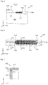
- Fig. 3 is a side view showing the schematic configuration of the welded part 140 which the energy storage device 10 according to this embodiment has.
- a gas release vent 170 existing at a position deeper than the second welded part 142 is indicated by a broken line.
- the energy storage device 10 includes the container 100 which has the container body 101, and the lid body 110 which closes the opening 102 of the container body 101.
- the elongated welded part 140 which is a welded portion between the container body 101 and the lid body 110 is formed on the container 100.
- the welded part 140 has the first welded parts 141 and the second welded part 142 arranged in a row in a lengthwise direction (the X axis direction in this embodiment) of the welded part 140, and a width W2 of the second welded part 142 in a widthwise direction (the Z axis direction in this embodiment) of the welded part 140 is set larger than a width W1 of the first welded part 141 in the Z axis direction.
- the gas release vent 170 is disposed on the lid body 110, and the second welded part 142 is disposed on a lateral side (a viewer's side in Fig. 3 ) of the gas release vent 170.
- a length L2 of the second welded part 142 in the X axis direction is set larger than a length L3 of the gas release vent 170 in the X axis direction.
- the elongated welded part 140 has the first welded parts 141, and the second welded part 142 having the larger width than the first welded part 141.
- the width W1 of the first welded parts 141 and the width W2 of the second welded part 142 are widths in the Z axis direction of welding marks which appear on a surface of the container 100 (in a direction along which the container body 101 and the lid body 110 are butted to each other).
- the welded part 140 is formed of: the first welded parts 141 which can be formed at a relatively high speed; and the second welded part 142 where a melting amount of metal (per unit length, the same definition used in the description made hereinafter) is relatively large.
- a joint strength between the container body 101 and the lid body 110 can be enhanced at least at a portion where the second welded part 142 exists. Accordingly, for example, it is possible to enhance reliability of joining of a portion of the lid body 110 which is liable to be affected by the increase of an internal pressure in the container 100 while suppressing lowering of efficiency of an entire welding operation.
- the gas release vent 170 is formed by reducing a wall thickness of a portion of a metal plate which is a material for forming the lid body 110. Accordingly, the portion of the lid body 110 where the gas release vent 170 is formed is a portion having lower rigidity than other portions of the lid body 110. Accordingly, such a portion is a portion which is liable to be affected by the increase of an internal pressure in the container 100.
- the second welded part 142 which is formed with a large width and is longer than the gas release vent 170 is disposed on a lateral side of the gas release vent 170 and hence, resistance of the lid body 110 against the increase of an internal pressure in the container 100 can be enhanced. Accordingly, the energy storage device 10 of this embodiment is an energy storage device having high quality.
- the second welded part 142 is disposed at the position where the second welded part 142 covers the entire length of the gas release vent 170 in the X axis direction as viewed from the lateral side.
- the second welded part 142 exists on the entire region on the lateral side of the gas release vent 170.
- the entire length of the gas release vent 170 overlaps with the second welded part 142 in the X axis direction. That is, the second welded part 142 is formed over the entire region on the side of the portion of the lid body 110 having lower rigidity than other portions of the lid body 110 and hence, a force for fixing the portion of the lid body 110 to the container body 101 can be further enhanced. As a result, reliability of the container 100 is further enhanced.
- L2 may be set to a value which falls within a range of from 0.2L1 to 0.8L1 inclusive. More preferably, L2 may be set to a value which falls within a range of from 0.2L1 to 0.5L1 inclusive.
- a range of the second welded part 142 is limited to a portion where the further increase of a joint strength between the container body 101 and the lid body 110 is desirable such as a center portion of the elongated lid body 110. Accordingly, it is possible to acquire both the prevention of lowering of efficiency of an entire welding operation and the enhancement of reliability of the container 100.
- the welded part 140 is formed such that the width of the portion positioned on the lateral side of the gas release vent 170 becomes large.
- the welded part 140 having such a configuration is formed on the container 100 of the energy storage device 10 through welding steps described hereinafter, for example.
- Fig. 4 is a view showing a step of forming the first welded part 141 according to this embodiment.
- Fig. 5 is a view showing a step of forming the second welded part 142 according to this embodiment.
- Fig. 6 is a view showing a portion of the configuration shown in Fig. 5 in an enlarged manner.
- the first welded part 141 included in the welded part 140 is formed by advancing the irradiation position of a laser beam 700 relatively straightforward along a straight-line butting portion 180 formed between the container body 101 and the lid body 110. This step is expressed as "straight-line welding step", for example.
- the first welded part 141 is formed, for example, by fixing the container 100 and, then, by advancing the irradiation position of the laser beam 700 along the butting portion 180.
- the second welded part 142 having a larger width than the first welded part 141 is formed.
- the second welded part 142 is formed by moving the irradiation position of the laser beam 700 along the butting portion 180 and, at the same time, by moving the irradiation position in the direction which intersects with the direction of moving of the irradiation position along the butting portion 180. This step is expressed as "non-straight-line welding step", for example.
- the second welded part 142 having a larger width than the first welded part 141 is formed. Further, by performing welding while rotating the irradiation position of the laser beam 700 as described above, for example, a welding depth of the second welded part 142 (a width of the second welded part 142 in the Y axis direction) can be made uniform in the length direction of the second welded part 142. That is, irregularities in welding depth in the X axis direction can be decreased. With such a configuration, it is possible to enhance a joint strength between the container body 101 and the lid body 110 at the second welded part 142.
- Fig. 7 is a cross-sectional view taken along a line VII-VII in Fig. 6
- Fig. 8 is a cross-sectional view taken along a line VIII-VIII in Fig. 6 .
- the illustration of constitutional elements housed in the container 100 such as the electrode assembly 400 is omitted.
- the omission of the illustration of the constitutional parts in the container 100 is made in Fig. 11 and Fig. 12 described later.
- the width W2 of the second welded part 142 is larger than the width W1 of the first welded part 141.
- a melting amount of metal at the second welded part 142 is larger than a melting amount of metal at the first welded part 141. That is, the second welded part 142 is formed such that the joint strength between the container body 101 and the lid body 110 at the second welded part 142 is higher than the joint strength between the container body 101 and the lid body 110 at the first welded part 141.
- the method of manufacturing the energy storage device 10 includes the welding step of forming the welded part 140 which is a welded portion between the container body 101 and the lid body 110, and the welded part 140 includes the first welded part 141 and the second welded part 142 disposed in a row in a lengthwise direction of the welded part 140.
- This welding step includes the straight-line welding step of forming the first welded part 141, and the non-straight-line welding step of forming the second welded part 142.
- the first welded part 141 is formed by advancing the irradiation position of the laser beam 700 relatively straightforward along the straight-line-shaped butting portion 180 between the container body 101 and the lid body 110.
- the second welded part 142 is formed by moving the irradiation position of the laser beam 700 along the butting portion 180 and, at the same time, by moving the irradiation position in the direction which intersects with the direction of moving of the irradiation position along the butting portion 180.
- the straight-line welded part 140 it is possible to form the straight-line welded part 140 as a whole while forming a portion of the welded part 140 with a large width by changing the irradiation position of the laser beam 700 relative to the container 100.
- the welded part 140 which includes the first welded part 141 and the second welded part 142 can be formed by a series of operation where the irradiation position of the laser beam 700 relative to the container 100 is controlled while continuing the irradiation of the laser beam 700 to the container 100 from a laser unit.
- the welded part 140 can be formed by a series of operations and, at the same time, the portion of the welded part 140 can be formed while increasing the joint strength of the portion compared to the joint strength of other portions. With such a configuration, it is possible to suppress the lowering of efficiency of the entire welding operation, and the portion of the lid body 110 having relatively low rigidity (the portion where the gas release vent 170 is disposed in this embodiment) can be firmly fixed to the container body 101. That is, it is possible to efficiently manufacture the energy storage device 10 having high quality.
- the second welded part 142 which the welded part 140 includes may be formed by a technique different from the technique shown in Fig. 6 .
- Fig. 9 and Fig. 10 are views respectively showing examples relating to other techniques for forming the second welded part 142.
- the second welded part 142 may be formed by irradiating a laser beam 700 to the butting portion 180 such that a trajectory of the irradiation position of the laser beam 700 forms a zigzag shape.
- the second welded part 142 may be formed by moving the irradiation position of the laser beam 700 along the butting portion 180 and by turning back the irradiation position at a predetermined position.
- the position of the container 100 in the Z axis direction to which the laser beam 700 is irradiated differs before and after the turning back of the irradiation position.
- the laser beam 700 is not irradiated to the butting portion 180 doubly but the laser beam 700 is irradiated while displacing the irradiation position of the laser beam 700 in a direction which intersects with the main moving direction (X axis direction) of the irradiation position of the laser beam 700.
- the second welded part 142 having a larger width than the first welded part 141 can be formed.
- the second welded part 142 having a larger width than the first welded part 141 may be formed by irradiating a laser beam 700 to the butting portion 180 such that a trajectory of the irradiation position of the laser beam 700 forms a sinusoidal wave or a rectangular wave.
- the irradiation position of the laser beam 700 is moved along the extending direction of the butting portion 180, and at least at a portion within the region, the irradiation position is moved in the direction which intersects with the moving direction of the irradiation position along the extending direction of the butting portion 180.
- the second welded part 142 having a larger width than the first welded part 141 may be formed by changing a beam width (spot size) of the laser beam 700.
- the first welded part 141 is formed by advancing the irradiation position of a laser beam 700 along the butting portion 180 and, then, when the irradiation position enters a range where the second welded part 142 is to be formed, the spot size of the laser beam 700 is increased and the irradiation position of the laser beam 700 is advanced straightforward so that the second welded part 142 is formed.
- the second welded part 142 having a larger width than the first welded part 141 may be formed as described above.
- the width W2 of the second welded part 142 in the Z axis direction is set larger than the width W1 of the first welded part 141 in the Z axis direction.
- a width of the second welded part 142 in the widthwise direction in the welded part 140 is larger than a width of the first welded part 141 in the widthwise direction. That is, it is sufficient that the width of the second welded part 142 is larger than the width of the first welded part 141 in at least one of directions orthogonal to the lengthwise direction of the welded part 140.
- Fig. 11 is a view showing the first welded part 141 and the second welded part 142 which differ from each other in width in the wall thickness direction of the container body 101.
- the illustration of the lid body 110 is omitted.
- a width of the first welded part 141 and a width of the second welded part 142 shown in Fig. 11 are defined as lengths in the wall thickness direction (Y-axis direction) of the container body 101 which is a direction intersecting with the lengthwise direction (X axis direction) of the welded part 140.
- a width W22 of the second welded part 142 in the Y axis direction is larger than a width W11 of the first welded part 141 in the Y axis direction.
- a joint strength of the second welded part 142 can be relatively increased.
- by disposing the second welded part 142 on the lateral side of the gas release vent 170, and by setting a length of the second welded part 142 in the X axis direction longer than a length of the gas release vent 170 in the X axis direction it is possible to acquire advantageous effects such as the enhancement of resistance of the lid body 110 against the increase of an internal pressure in the container 100 can be enhanced as described previously.
- a wall thickness of a portion of the container 100 corresponding to the first welded part 141 may be set larger than a wall thickness of a portion of the container 100 corresponding the second welded part 142.
- the width W22 of the second welded part 142 in the Y axis direction can be further increased.
- the first welded part 141 and the second welded part 142 shown in Fig. 11 may be formed by adjusting a strength of a laser beam 700, a moving speed of the laser beam 700 or the like, for example.
- the first welded part 141 is formed by advancing an irradiation position of a laser beam 700 along the butting portion 180 at a predetermined speed and, thereafter, when the irradiation position of the laser beam 700 enters a region where the second welded part 142 is to be formed, the irradiation position of the laser beam 700 is advanced straightforward while lowering a moving speed thus forming the second welded part 142.
- the second welded part 142 having a larger width than the first welded part 141 may be formed in this manner.
- the energy storage device according to the present invention has been described with reference to the embodiment and the modifications heretofore.
- the present invention is not limited to the above-mentioned embodiments and modifications.
- the configurations acquired by applying various modifications which those who are skilled in the art conceive to the previously-mentioned embodiments or modifications, and the configurations acquired by combining the plurality of constitutional elements described above fall within the scope of the present invention unless these configurations depart from the gist of the present invention.
- a welded part 140 having the same configuration as the welded part 140 described above may be also formed on a long-side surface on a depth side in Fig. 1 (a plus side in the Y axis direction). That is, the second welded part 142 having a larger width than the first welded part 141 may be formed on both sides of the container 100 with the gas release vent 170 interposed therebetween.
- widths of two second welded parts 142 may differ from each other corresponding to distances from the gas release vent 170 to the respective welded parts 142, for example.
- Fig. 12 is a partially cross-sectional view of a container 100 having a gas release vent 170a disposed closer to one of two long-side surfaces of the container 100.
- a width W2a of a second welded part 142a which is formed on a left long-side surface side may be set larger than a width W2b of the second welded part 142b which is formed on a right long-side surface side.
- a portion of the lid body 110 where rigidity is lowered due to the existence of the gas release vent 170a can be reinforced more effectively.
- the gas release vent 170 is disposed at a center portion of the lid body 110 in the lengthwise direction of the lid body 110, and the second welded part 142 is disposed at a center portion of the welded part 140 corresponding to the gas release vent 170.
- the position of the gas release vent 170 in the lengthwise direction of the lid body 110 is not limited to the center portion, and the gas release vent 170 may be disposed at an end portion of the lid body 110 in the lengthwise direction of the lid body 110.
- the straight-line welded part 140 may have: the second welded part 142 which extends to a position beyond the gas release vent 170 from a left end of the lid body 110; and a first welded part 141 which extends to a right end of the lid body 110 on a right side of the second welded part 142.
- the width W1 of the first welded part 141 and the width W2 of the second welded part 142 are respectively set to a fixed value in a length direction.
- a maximum value or an average value of widths of the first welded part 141 in the Z axis direction or in the Y axis direction may be defined as a width W1 of the first welded part 141.
- the first welded part 141 and the second welded part 142 may be differentiated from each other based on the difference in an irradiation mode of a laser beam 700 (a moving speed, a moving trajectory, a spot size of an irradiation position of the laser beam 700, intensity of the laser beam 700 or the like), for example.
- the welded part 140 is divided into plural sections for respective predetermined lengths by zoning, an average value of a width in the Z axis direction or in the Y axis direction is obtained for every section, and the section where the average value is larger than a threshold value may be defined as the second welded part 142, and a section where the average value is equal to or less than the threshold value may be defined as the first welded part 141.
- a posture of the winding-type electrode assembly 400 which the energy storage device 10 includes is not particularly limited.
- the electrode assembly 400 may be housed in the container body 101 in a posture that a winding axis is arranged parallel to the lengthwise direction (X axis direction) of the lid body 110.
- An electrode assembly which the energy storage device 10 includes is not limited to a winding type electrode assembly.
- the energy storage device 10 may include a stacking-type electrode assembly formed by stacking planar electrode plates, or may include an electrode assembly formed by stacking elongated-strip electrode plates in a bellows shape by repeating mounting folding and valley folding, for example.
- the present invention is applicable to an energy storage device such as a lithium ion secondary battery, a manufacturing method for manufacturing such an energy storage device and the like.
Landscapes
- Optics & Photonics (AREA)
- Physics & Mathematics (AREA)
- Engineering & Computer Science (AREA)
- Electrochemistry (AREA)
- General Chemical & Material Sciences (AREA)
- Chemical & Material Sciences (AREA)
- Chemical Kinetics & Catalysis (AREA)
- Plasma & Fusion (AREA)
- Mechanical Engineering (AREA)
- Sealing Battery Cases Or Jackets (AREA)
- Laser Beam Processing (AREA)
- Electric Double-Layer Capacitors Or The Like (AREA)
- Gas Exhaust Devices For Batteries (AREA)
Claims (4)
- Energiespeichervorrichtung (10), die mit einem Behälter (100) mit einem Behälterkörper (101) und einem Deckelkörper (110) ausgestattet ist, der eine Öffnung (102) des Behälterkörpers (101) verschließt, wobei
ein längliches geschweißtes Teil (140), das ein geschweißter Anteil zwischen dem Behälterkörper (101) und dem Deckelkörper (110) ist, auf dem Behälter (100) ausgebildet ist,
das geschweißte Teil (140) ein erstes geschweißtes Teil (141) und ein zweites geschweißtes Teil (142) aufweist, die in einer Reihe in Längsrichtung des geschweißten Teils (140) angeordnet sind,
eine Breite des zweiten geschweißten Teils (142) in einer Breitenrichtung des geschweißten Teils (140) größer als eine Breite des ersten geschweißten Teils (141) in der Breitenrichtung festgelegt ist,
dadurch gekennzeichnet, dass:eine Gasablassbohrung (170) auf dem Deckelkörper (110) angeordnet ist,das zweite geschweißte Teil (142) nur auf einer lateralen Seite oder beiden lateralen Seiten der Gasablassbohrung (170) angeordnet ist und eine Gesamtlänge der Gasablassbohrung (170) in der Längsrichtung einschließt, betrachtet von der lateralen Seite, undeine Länge des zweiten geschweißten Teils (142) in der Längsrichtung größer als eine Länge der Gasablassbohrung (170) in der Längsrichtung festgelegt ist. - Energiespeichervorrichtung (10) nach Anspruch 1, wobei das zweite geschweißte Teil (142) an einer Position angeordnet ist, bei der das zweite geschweißte Teil (142) eine Gesamtlänge der Gasablassbohrung (170) in der Längsrichtung einschließt, betrachtet von der lateralen Seite.
- Energiespeichervorrichtung (10) nach Anspruch 1 oder Anspruch 2, wobei unter Annahme einer Länge des geschweißten Teils (140) in der Längsrichtung als L eine Länge des zweiten geschweißten Teils (142) auf einen Wert festgelegt wird, der in einen Bereich von 0,2 L bis 0,8 L einschließlich fällt.
- Verfahren zum Fertigen einer Energiespeichervorrichtung (10), das durch die folgenden Schritte gekennzeichnet ist:Bereitstellen einer Energiespeichervorrichtung (10), die mit einem Behälter (100) mit einem Behälterkörper (101) und einem Deckelkörper (110) ausgestattet ist, der eine Öffnung (102) des Behälterkörpers (101) verschließt und auf dem eine Gasablassbohrung (170) angeordnet ist, wobei das Verfahren einen Schweißschritt des Bildens eines geschweißten Teils (140) umfasst, das ein geschweißter Anteil zwischen dem Behälterkörper (101) und dem Deckelkörper (110) ist und ein erstes geschweißtes Teil (141) und ein zweites geschweißtes Teil (142) einschließt, die in einer Reihe in einer Längsrichtung des geschweißten Teils (140) angeordnet sind,wobei der Schweißschritt umfasst:einen geradlinigen Schweißschritt des Bildens des ersten geschweißten Teils (141) durch Vorrücken einer Bestrahlungsposition eines Laserstrahls relativ gerade entlang eines geradlinig geformten Anfügeanteils zwischen dem Behälterkörper (101) und dem Deckelkörper (110); undeinen nicht-geradlinigen Schweißschritt des Bildens des zweiten geschweißten Teils (142) nur auf einer lateralen Seite oder beiden lateralen Seiten der Gasablassbohrung (170), wobei das zweite geschweißte Teil (142) eine Gesamtlänge der Gasablassbohrung (170) in der Längsrichtung einschließt, betrachtet von der lateralen Seite, indem die Bestrahlungsposition des Laserstrahls entlang der Anfügeposition bewegt wird und gleichzeitig die Bestrahlungsposition in eine Richtung bewegt wird, welche eine Bewegungsrichtung der Bestrahlungsposition entlang des Anfügeanteils schneidet, so dass eine Breite des zweiten geschweißten Teils (142) in einer Breitenrichtung des geschweißten Teils (140) größer als eine Breite des ersten geschweißten Teils (141) in der Breitenrichtung ist.
Applications Claiming Priority (2)
| Application Number | Priority Date | Filing Date | Title |
|---|---|---|---|
| JP2016139836A JP6725351B2 (ja) | 2016-07-14 | 2016-07-14 | 蓄電素子及び蓄電素子の製造方法 |
| PCT/EP2017/066914 WO2018011049A1 (en) | 2016-07-14 | 2017-07-06 | Energy storage device and method of manufacturing such energy storage device |
Publications (2)
| Publication Number | Publication Date |
|---|---|
| EP3484657A1 EP3484657A1 (de) | 2019-05-22 |
| EP3484657B1 true EP3484657B1 (de) | 2020-09-09 |
Family
ID=59285245
Family Applications (1)
| Application Number | Title | Priority Date | Filing Date |
|---|---|---|---|
| EP17735542.7A Active EP3484657B1 (de) | 2016-07-14 | 2017-07-06 | Energiespeichervorrichtung und verfahren zur herstellung solch einer energiespeichervorrichtung |
Country Status (5)
| Country | Link |
|---|---|
| US (1) | US11407064B2 (de) |
| EP (1) | EP3484657B1 (de) |
| JP (1) | JP6725351B2 (de) |
| CN (1) | CN109475979B (de) |
| WO (1) | WO2018011049A1 (de) |
Families Citing this family (12)
| Publication number | Priority date | Publication date | Assignee | Title |
|---|---|---|---|---|
| US11189875B1 (en) | 2016-12-09 | 2021-11-30 | Green Cubes Technology, Llc | Battery systems containing recyclable battery portions |
| JP7247893B2 (ja) | 2017-12-12 | 2023-03-29 | 株式会社Gsユアサ | 蓄電素子 |
| JP1646183S (de) * | 2019-02-27 | 2019-11-25 | ||
| KR102777925B1 (ko) | 2019-05-29 | 2025-03-10 | 삼성에스디아이 주식회사 | 이차 전지 |
| CN113927172B (zh) * | 2020-06-29 | 2024-07-05 | 阿帕奇(北京)光纤激光技术有限公司 | 激光去毛刺和倒角的方法和系统 |
| JP7673373B2 (ja) * | 2020-09-16 | 2025-05-09 | 株式会社Gsユアサ | 蓄電装置 |
| USD1001064S1 (en) * | 2021-12-10 | 2023-10-10 | Pan CHEN | Portable power bank |
| USD984962S1 (en) * | 2021-12-10 | 2023-05-02 | Pan CHEN | Portable power bank |
| CN114985927B (zh) * | 2022-05-31 | 2023-07-18 | 广东舜元激光科技有限公司 | 电芯的焊接装置及焊接方法 |
| CN115302069B (zh) * | 2022-08-30 | 2024-05-03 | 广东利元亨智能装备股份有限公司 | 密封钉焊接方法、设备、计算机可读存储介质及处理器 |
| USD1078610S1 (en) * | 2024-01-04 | 2025-06-10 | Ugreen Group Limited | Emergency power supply |
| JPWO2025244000A1 (de) * | 2024-05-20 | 2025-11-27 |
Family Cites Families (17)
| Publication number | Priority date | Publication date | Assignee | Title |
|---|---|---|---|---|
| JP3233841B2 (ja) | 1995-10-31 | 2001-12-04 | 三菱重工業株式会社 | 電池ケースの上蓋のレーザ溶接方法 |
| JP2001043845A (ja) * | 1999-07-28 | 2001-02-16 | Fuji Elelctrochem Co Ltd | 角形電池の防爆機構 |
| JP3657539B2 (ja) | 2001-06-20 | 2005-06-08 | アトムリビンテック株式会社 | 折畳椅子 |
| JP2003031186A (ja) * | 2001-07-18 | 2003-01-31 | Sony Corp | 電池及び電池に対するマーキング方法 |
| US7491464B2 (en) * | 2003-01-03 | 2009-02-17 | The Gillette Company | Alkaline cell with flat housing |
| JP3973164B2 (ja) * | 2003-11-21 | 2007-09-12 | 日立マクセル株式会社 | 密閉角形電池 |
| EP1716607A2 (de) * | 2003-11-26 | 2006-11-02 | The Gillette Company | Alkalizelle mit flachgehäuse |
| JP4929606B2 (ja) | 2005-03-16 | 2012-05-09 | トヨタ自動車株式会社 | 密閉型蓄電装置及びその製造方法 |
| JP2010205441A (ja) | 2009-02-27 | 2010-09-16 | Sanyo Electric Co Ltd | 角形密閉電池の製造方法及び角形密閉電池 |
| JP2010238558A (ja) * | 2009-03-31 | 2010-10-21 | Sanyo Electric Co Ltd | 角形密閉型電池 |
| JP2011129266A (ja) | 2009-12-15 | 2011-06-30 | Sanyo Electric Co Ltd | 角形密閉電池の製造方法 |
| KR101189526B1 (ko) | 2010-09-30 | 2012-10-11 | 주식회사 엘티에스 | 레이저를 이용한 와이드 프릿 실링방법 |
| JP6518031B2 (ja) * | 2013-04-30 | 2019-05-22 | 株式会社Gsユアサ | 蓄電素子製造方法、溶接制御プログラム |
| US9515297B2 (en) | 2013-07-19 | 2016-12-06 | Samsung Sdi Co., Ltd. | Rechargeable battery |
| JP2015030011A (ja) | 2013-08-02 | 2015-02-16 | 日本アビオニクス株式会社 | レーザ接合方法、密閉電池の製造方法、レーザ接合装置および密閉電池 |
| JP6158356B2 (ja) | 2014-01-17 | 2017-07-05 | 株式会社日立製作所 | レーザ溶接方法及び溶接継手 |
| JP2015111573A (ja) | 2014-12-22 | 2015-06-18 | トヨタ自動車株式会社 | 電池およびその製造方法 |
-
2016
- 2016-07-14 JP JP2016139836A patent/JP6725351B2/ja active Active
-
2017
- 2017-07-06 EP EP17735542.7A patent/EP3484657B1/de active Active
- 2017-07-06 CN CN201780042955.5A patent/CN109475979B/zh active Active
- 2017-07-06 WO PCT/EP2017/066914 patent/WO2018011049A1/en not_active Ceased
- 2017-07-06 US US16/317,004 patent/US11407064B2/en active Active
Non-Patent Citations (1)
| Title |
|---|
| None * |
Also Published As
| Publication number | Publication date |
|---|---|
| US20190299332A1 (en) | 2019-10-03 |
| US11407064B2 (en) | 2022-08-09 |
| WO2018011049A1 (en) | 2018-01-18 |
| EP3484657A1 (de) | 2019-05-22 |
| CN109475979A (zh) | 2019-03-15 |
| CN109475979B (zh) | 2020-12-04 |
| JP2018010815A (ja) | 2018-01-18 |
| JP6725351B2 (ja) | 2020-07-15 |
Similar Documents
| Publication | Publication Date | Title |
|---|---|---|
| US11407064B2 (en) | Energy storage device and method of manufacturing energy storage device | |
| JP7687776B2 (ja) | 電極端子のリベット構造とそれを含む二次電池、バッテリパック、および自動車 | |
| US11664560B2 (en) | Secondary battery and method of manufacturing the same | |
| JP7675188B2 (ja) | 電極組立体、バッテリー、それを含むバッテリーパック及び自動車 | |
| JP6138963B2 (ja) | 角形電池 | |
| US11264679B2 (en) | Secondary battery | |
| JP7617141B2 (ja) | 電極組立体及びその製造方法、電極組立体を含む円筒形バッテリーセル、並びに円筒形バッテリーセルを含むバッテリーパックと自動車 | |
| KR101147175B1 (ko) | 이차전지 | |
| US11509025B2 (en) | Secondary battery and method of manufacturing the same | |
| JP7639133B2 (ja) | 二次電池、及びこれを含む電池パック及び自動車 | |
| JP7659056B2 (ja) | 二次電池、及びこれを含む電池パック及び自動車 | |
| US20250201973A1 (en) | Energy storage device | |
| JP2023074168A (ja) | 電池 | |
| KR102908431B1 (ko) | 이차 전지 | |
| EP4169657A1 (de) | Verfahren zur herstellung einer sekundärbatterie | |
| JP7694558B2 (ja) | 蓄電装置及びその製造方法 | |
| JP6640467B2 (ja) | 二次電池、二次電池の製造方法 | |
| JP7567879B2 (ja) | 電池、電池モジュールおよび電池の製造方法 | |
| EP4447203B1 (de) | Batteriezelle und herstellungsverfahren dafür, batterie und elektrische vorrichtung | |
| EP4418413A1 (de) | Elektrische speichervorrichtung | |
| KR20250108429A (ko) | 배터리 셀 및 배터리 셀의 케이스 제조 방법 | |
| KR20250175957A (ko) | 전극 조립체 및 이를 포함하는 배터리 셀 | |
| JP2024151458A (ja) | 電池セルおよびその製造方法 | |
| JP2025068376A (ja) | 電池セルおよびその製造方法 | |
| JP2026040908A (ja) | 蓄電デバイスの製造方法および蓄電デバイス |
Legal Events
| Date | Code | Title | Description |
|---|---|---|---|
| STAA | Information on the status of an ep patent application or granted ep patent |
Free format text: STATUS: UNKNOWN |
|
| STAA | Information on the status of an ep patent application or granted ep patent |
Free format text: STATUS: THE INTERNATIONAL PUBLICATION HAS BEEN MADE |
|
| PUAI | Public reference made under article 153(3) epc to a published international application that has entered the european phase |
Free format text: ORIGINAL CODE: 0009012 |
|
| STAA | Information on the status of an ep patent application or granted ep patent |
Free format text: STATUS: REQUEST FOR EXAMINATION WAS MADE |
|
| 17P | Request for examination filed |
Effective date: 20190213 |
|
| AK | Designated contracting states |
Kind code of ref document: A1 Designated state(s): AL AT BE BG CH CY CZ DE DK EE ES FI FR GB GR HR HU IE IS IT LI LT LU LV MC MK MT NL NO PL PT RO RS SE SI SK SM TR |
|
| AX | Request for extension of the european patent |
Extension state: BA ME |
|
| DAV | Request for validation of the european patent (deleted) | ||
| DAX | Request for extension of the european patent (deleted) | ||
| GRAP | Despatch of communication of intention to grant a patent |
Free format text: ORIGINAL CODE: EPIDOSNIGR1 |
|
| STAA | Information on the status of an ep patent application or granted ep patent |
Free format text: STATUS: GRANT OF PATENT IS INTENDED |
|
| RAP1 | Party data changed (applicant data changed or rights of an application transferred) |
Owner name: ROBERT BOSCH GMBH Owner name: GS YUASA INTERNATIONAL LTD. |
|
| INTG | Intention to grant announced |
Effective date: 20200406 |
|
| GRAS | Grant fee paid |
Free format text: ORIGINAL CODE: EPIDOSNIGR3 |
|
| GRAA | (expected) grant |
Free format text: ORIGINAL CODE: 0009210 |
|
| STAA | Information on the status of an ep patent application or granted ep patent |
Free format text: STATUS: THE PATENT HAS BEEN GRANTED |
|
| AK | Designated contracting states |
Kind code of ref document: B1 Designated state(s): AL AT BE BG CH CY CZ DE DK EE ES FI FR GB GR HR HU IE IS IT LI LT LU LV MC MK MT NL NO PL PT RO RS SE SI SK SM TR |
|
| REG | Reference to a national code |
Ref country code: GB Ref legal event code: FG4D |
|
| REG | Reference to a national code |
Ref country code: AT Ref legal event code: REF Ref document number: 1310972 Country of ref document: AT Kind code of ref document: T Effective date: 20200915 Ref country code: CH Ref legal event code: EP |
|
| REG | Reference to a national code |
Ref country code: IE Ref legal event code: FG4D |
|
| REG | Reference to a national code |
Ref country code: DE Ref legal event code: R096 Ref document number: 602017023321 Country of ref document: DE |
|
| REG | Reference to a national code |
Ref country code: LT Ref legal event code: MG4D |
|
| PG25 | Lapsed in a contracting state [announced via postgrant information from national office to epo] |
Ref country code: FI Free format text: LAPSE BECAUSE OF FAILURE TO SUBMIT A TRANSLATION OF THE DESCRIPTION OR TO PAY THE FEE WITHIN THE PRESCRIBED TIME-LIMIT Effective date: 20200909 Ref country code: GR Free format text: LAPSE BECAUSE OF FAILURE TO SUBMIT A TRANSLATION OF THE DESCRIPTION OR TO PAY THE FEE WITHIN THE PRESCRIBED TIME-LIMIT Effective date: 20201210 Ref country code: NO Free format text: LAPSE BECAUSE OF FAILURE TO SUBMIT A TRANSLATION OF THE DESCRIPTION OR TO PAY THE FEE WITHIN THE PRESCRIBED TIME-LIMIT Effective date: 20201209 Ref country code: SE Free format text: LAPSE BECAUSE OF FAILURE TO SUBMIT A TRANSLATION OF THE DESCRIPTION OR TO PAY THE FEE WITHIN THE PRESCRIBED TIME-LIMIT Effective date: 20200909 Ref country code: BG Free format text: LAPSE BECAUSE OF FAILURE TO SUBMIT A TRANSLATION OF THE DESCRIPTION OR TO PAY THE FEE WITHIN THE PRESCRIBED TIME-LIMIT Effective date: 20201209 Ref country code: HR Free format text: LAPSE BECAUSE OF FAILURE TO SUBMIT A TRANSLATION OF THE DESCRIPTION OR TO PAY THE FEE WITHIN THE PRESCRIBED TIME-LIMIT Effective date: 20200909 Ref country code: LT Free format text: LAPSE BECAUSE OF FAILURE TO SUBMIT A TRANSLATION OF THE DESCRIPTION OR TO PAY THE FEE WITHIN THE PRESCRIBED TIME-LIMIT Effective date: 20200909 |
|
| REG | Reference to a national code |
Ref country code: AT Ref legal event code: MK05 Ref document number: 1310972 Country of ref document: AT Kind code of ref document: T Effective date: 20200909 |
|
| REG | Reference to a national code |
Ref country code: NL Ref legal event code: MP Effective date: 20200909 |
|
| PG25 | Lapsed in a contracting state [announced via postgrant information from national office to epo] |
Ref country code: RS Free format text: LAPSE BECAUSE OF FAILURE TO SUBMIT A TRANSLATION OF THE DESCRIPTION OR TO PAY THE FEE WITHIN THE PRESCRIBED TIME-LIMIT Effective date: 20200909 Ref country code: LV Free format text: LAPSE BECAUSE OF FAILURE TO SUBMIT A TRANSLATION OF THE DESCRIPTION OR TO PAY THE FEE WITHIN THE PRESCRIBED TIME-LIMIT Effective date: 20200909 Ref country code: PL Free format text: LAPSE BECAUSE OF FAILURE TO SUBMIT A TRANSLATION OF THE DESCRIPTION OR TO PAY THE FEE WITHIN THE PRESCRIBED TIME-LIMIT Effective date: 20200909 |
|
| PG25 | Lapsed in a contracting state [announced via postgrant information from national office to epo] |
Ref country code: SM Free format text: LAPSE BECAUSE OF FAILURE TO SUBMIT A TRANSLATION OF THE DESCRIPTION OR TO PAY THE FEE WITHIN THE PRESCRIBED TIME-LIMIT Effective date: 20200909 Ref country code: EE Free format text: LAPSE BECAUSE OF FAILURE TO SUBMIT A TRANSLATION OF THE DESCRIPTION OR TO PAY THE FEE WITHIN THE PRESCRIBED TIME-LIMIT Effective date: 20200909 Ref country code: CZ Free format text: LAPSE BECAUSE OF FAILURE TO SUBMIT A TRANSLATION OF THE DESCRIPTION OR TO PAY THE FEE WITHIN THE PRESCRIBED TIME-LIMIT Effective date: 20200909 Ref country code: RO Free format text: LAPSE BECAUSE OF FAILURE TO SUBMIT A TRANSLATION OF THE DESCRIPTION OR TO PAY THE FEE WITHIN THE PRESCRIBED TIME-LIMIT Effective date: 20200909 Ref country code: PT Free format text: LAPSE BECAUSE OF FAILURE TO SUBMIT A TRANSLATION OF THE DESCRIPTION OR TO PAY THE FEE WITHIN THE PRESCRIBED TIME-LIMIT Effective date: 20210111 |
|
| PG25 | Lapsed in a contracting state [announced via postgrant information from national office to epo] |
Ref country code: IS Free format text: LAPSE BECAUSE OF FAILURE TO SUBMIT A TRANSLATION OF THE DESCRIPTION OR TO PAY THE FEE WITHIN THE PRESCRIBED TIME-LIMIT Effective date: 20210109 Ref country code: AL Free format text: LAPSE BECAUSE OF FAILURE TO SUBMIT A TRANSLATION OF THE DESCRIPTION OR TO PAY THE FEE WITHIN THE PRESCRIBED TIME-LIMIT Effective date: 20200909 Ref country code: AT Free format text: LAPSE BECAUSE OF FAILURE TO SUBMIT A TRANSLATION OF THE DESCRIPTION OR TO PAY THE FEE WITHIN THE PRESCRIBED TIME-LIMIT Effective date: 20200909 Ref country code: ES Free format text: LAPSE BECAUSE OF FAILURE TO SUBMIT A TRANSLATION OF THE DESCRIPTION OR TO PAY THE FEE WITHIN THE PRESCRIBED TIME-LIMIT Effective date: 20200909 |
|
| REG | Reference to a national code |
Ref country code: DE Ref legal event code: R097 Ref document number: 602017023321 Country of ref document: DE |
|
| PG25 | Lapsed in a contracting state [announced via postgrant information from national office to epo] |
Ref country code: SK Free format text: LAPSE BECAUSE OF FAILURE TO SUBMIT A TRANSLATION OF THE DESCRIPTION OR TO PAY THE FEE WITHIN THE PRESCRIBED TIME-LIMIT Effective date: 20200909 |
|
| PLBE | No opposition filed within time limit |
Free format text: ORIGINAL CODE: 0009261 |
|
| STAA | Information on the status of an ep patent application or granted ep patent |
Free format text: STATUS: NO OPPOSITION FILED WITHIN TIME LIMIT |
|
| 26N | No opposition filed |
Effective date: 20210610 |
|
| PG25 | Lapsed in a contracting state [announced via postgrant information from national office to epo] |
Ref country code: DK Free format text: LAPSE BECAUSE OF FAILURE TO SUBMIT A TRANSLATION OF THE DESCRIPTION OR TO PAY THE FEE WITHIN THE PRESCRIBED TIME-LIMIT Effective date: 20200909 Ref country code: SI Free format text: LAPSE BECAUSE OF FAILURE TO SUBMIT A TRANSLATION OF THE DESCRIPTION OR TO PAY THE FEE WITHIN THE PRESCRIBED TIME-LIMIT Effective date: 20200909 |
|
| REG | Reference to a national code |
Ref country code: CH Ref legal event code: PL |
|
| GBPC | Gb: european patent ceased through non-payment of renewal fee |
Effective date: 20210706 |
|
| PG25 | Lapsed in a contracting state [announced via postgrant information from national office to epo] |
Ref country code: MC Free format text: LAPSE BECAUSE OF FAILURE TO SUBMIT A TRANSLATION OF THE DESCRIPTION OR TO PAY THE FEE WITHIN THE PRESCRIBED TIME-LIMIT Effective date: 20200909 |
|
| REG | Reference to a national code |
Ref country code: BE Ref legal event code: MM Effective date: 20210731 |
|
| PG25 | Lapsed in a contracting state [announced via postgrant information from national office to epo] |
Ref country code: LI Free format text: LAPSE BECAUSE OF NON-PAYMENT OF DUE FEES Effective date: 20210731 Ref country code: GB Free format text: LAPSE BECAUSE OF NON-PAYMENT OF DUE FEES Effective date: 20210706 Ref country code: CH Free format text: LAPSE BECAUSE OF NON-PAYMENT OF DUE FEES Effective date: 20210731 |
|
| PG25 | Lapsed in a contracting state [announced via postgrant information from national office to epo] |
Ref country code: LU Free format text: LAPSE BECAUSE OF NON-PAYMENT OF DUE FEES Effective date: 20210706 |
|
| PG25 | Lapsed in a contracting state [announced via postgrant information from national office to epo] |
Ref country code: IE Free format text: LAPSE BECAUSE OF NON-PAYMENT OF DUE FEES Effective date: 20210706 Ref country code: BE Free format text: LAPSE BECAUSE OF NON-PAYMENT OF DUE FEES Effective date: 20210731 |
|
| PG25 | Lapsed in a contracting state [announced via postgrant information from national office to epo] |
Ref country code: NL Free format text: LAPSE BECAUSE OF NON-PAYMENT OF DUE FEES Effective date: 20200923 Ref country code: CY Free format text: LAPSE BECAUSE OF FAILURE TO SUBMIT A TRANSLATION OF THE DESCRIPTION OR TO PAY THE FEE WITHIN THE PRESCRIBED TIME-LIMIT Effective date: 20200909 |
|
| PG25 | Lapsed in a contracting state [announced via postgrant information from national office to epo] |
Ref country code: HU Free format text: LAPSE BECAUSE OF FAILURE TO SUBMIT A TRANSLATION OF THE DESCRIPTION OR TO PAY THE FEE WITHIN THE PRESCRIBED TIME-LIMIT; INVALID AB INITIO Effective date: 20170706 |
|
| REG | Reference to a national code |
Ref country code: DE Ref legal event code: R081 Ref document number: 602017023321 Country of ref document: DE Owner name: GS YUASA INTERNATIONAL LTD., JP Free format text: FORMER OWNERS: GS YUASA INTERNATIONAL LTD., KYOTO-SHI, JP; ROBERT BOSCH GMBH, 70469 STUTTGART, DE |
|
| PG25 | Lapsed in a contracting state [announced via postgrant information from national office to epo] |
Ref country code: MK Free format text: LAPSE BECAUSE OF FAILURE TO SUBMIT A TRANSLATION OF THE DESCRIPTION OR TO PAY THE FEE WITHIN THE PRESCRIBED TIME-LIMIT Effective date: 20200909 |
|
| PG25 | Lapsed in a contracting state [announced via postgrant information from national office to epo] |
Ref country code: MT Free format text: LAPSE BECAUSE OF FAILURE TO SUBMIT A TRANSLATION OF THE DESCRIPTION OR TO PAY THE FEE WITHIN THE PRESCRIBED TIME-LIMIT Effective date: 20200909 |
|
| PGFP | Annual fee paid to national office [announced via postgrant information from national office to epo] |
Ref country code: FR Payment date: 20250620 Year of fee payment: 9 |
|
| PGFP | Annual fee paid to national office [announced via postgrant information from national office to epo] |
Ref country code: DE Payment date: 20250620 Year of fee payment: 9 |
|
| PGFP | Annual fee paid to national office [announced via postgrant information from national office to epo] |
Ref country code: IT Payment date: 20250619 Year of fee payment: 9 |
|
| PG25 | Lapsed in a contracting state [announced via postgrant information from national office to epo] |
Ref country code: TR Free format text: LAPSE BECAUSE OF FAILURE TO SUBMIT A TRANSLATION OF THE DESCRIPTION OR TO PAY THE FEE WITHIN THE PRESCRIBED TIME-LIMIT Effective date: 20200909 |