EP3484633B1 - Reduzierung der seitenkantenklebrigkeit einer klebebandrolle - Google Patents
Reduzierung der seitenkantenklebrigkeit einer klebebandrolle Download PDFInfo
- Publication number
- EP3484633B1 EP3484633B1 EP17731907.6A EP17731907A EP3484633B1 EP 3484633 B1 EP3484633 B1 EP 3484633B1 EP 17731907 A EP17731907 A EP 17731907A EP 3484633 B1 EP3484633 B1 EP 3484633B1
- Authority
- EP
- European Patent Office
- Prior art keywords
- adhesive tape
- roll
- adhesive
- acrylate
- face
- Prior art date
- Legal status (The legal status is an assumption and is not a legal conclusion. Google has not performed a legal analysis and makes no representation as to the accuracy of the status listed.)
- Active
Links
Images

Classifications
-
- B—PERFORMING OPERATIONS; TRANSPORTING
- B05—SPRAYING OR ATOMISING IN GENERAL; APPLYING FLUENT MATERIALS TO SURFACES, IN GENERAL
- B05D—PROCESSES FOR APPLYING FLUENT MATERIALS TO SURFACES, IN GENERAL
- B05D5/00—Processes for applying liquids or other fluent materials to surfaces to obtain special surface effects, finishes or structures
- B05D5/08—Processes for applying liquids or other fluent materials to surfaces to obtain special surface effects, finishes or structures to obtain an anti-friction or anti-adhesive surface
-
- C—CHEMISTRY; METALLURGY
- C09—DYES; PAINTS; POLISHES; NATURAL RESINS; ADHESIVES; COMPOSITIONS NOT OTHERWISE PROVIDED FOR; APPLICATIONS OF MATERIALS NOT OTHERWISE PROVIDED FOR
- C09J—ADHESIVES; NON-MECHANICAL ASPECTS OF ADHESIVE PROCESSES IN GENERAL; ADHESIVE PROCESSES NOT PROVIDED FOR ELSEWHERE; USE OF MATERIALS AS ADHESIVES
- C09J7/00—Adhesives in the form of films or foils
- C09J7/30—Adhesives in the form of films or foils characterised by the adhesive composition
- C09J7/38—Pressure-sensitive adhesives [PSA]
-
- C—CHEMISTRY; METALLURGY
- C09—DYES; PAINTS; POLISHES; NATURAL RESINS; ADHESIVES; COMPOSITIONS NOT OTHERWISE PROVIDED FOR; APPLICATIONS OF MATERIALS NOT OTHERWISE PROVIDED FOR
- C09J—ADHESIVES; NON-MECHANICAL ASPECTS OF ADHESIVE PROCESSES IN GENERAL; ADHESIVE PROCESSES NOT PROVIDED FOR ELSEWHERE; USE OF MATERIALS AS ADHESIVES
- C09J7/00—Adhesives in the form of films or foils
- C09J7/40—Adhesives in the form of films or foils characterised by release liners
- C09J7/401—Adhesives in the form of films or foils characterised by release liners characterised by the release coating composition
-
- B—PERFORMING OPERATIONS; TRANSPORTING
- B05—SPRAYING OR ATOMISING IN GENERAL; APPLYING FLUENT MATERIALS TO SURFACES, IN GENERAL
- B05D—PROCESSES FOR APPLYING FLUENT MATERIALS TO SURFACES, IN GENERAL
- B05D1/00—Processes for applying liquids or other fluent materials
- B05D1/62—Plasma-deposition of organic layers
-
- B—PERFORMING OPERATIONS; TRANSPORTING
- B05—SPRAYING OR ATOMISING IN GENERAL; APPLYING FLUENT MATERIALS TO SURFACES, IN GENERAL
- B05D—PROCESSES FOR APPLYING FLUENT MATERIALS TO SURFACES, IN GENERAL
- B05D2252/00—Sheets
-
- C—CHEMISTRY; METALLURGY
- C23—COATING METALLIC MATERIAL; COATING MATERIAL WITH METALLIC MATERIAL; CHEMICAL SURFACE TREATMENT; DIFFUSION TREATMENT OF METALLIC MATERIAL; COATING BY VACUUM EVAPORATION, BY SPUTTERING, BY ION IMPLANTATION OR BY CHEMICAL VAPOUR DEPOSITION, IN GENERAL; INHIBITING CORROSION OF METALLIC MATERIAL OR INCRUSTATION IN GENERAL
- C23C—COATING METALLIC MATERIAL; COATING MATERIAL WITH METALLIC MATERIAL; SURFACE TREATMENT OF METALLIC MATERIAL BY DIFFUSION INTO THE SURFACE, BY CHEMICAL CONVERSION OR SUBSTITUTION; COATING BY VACUUM EVAPORATION, BY SPUTTERING, BY ION IMPLANTATION OR BY CHEMICAL VAPOUR DEPOSITION, IN GENERAL
- C23C16/00—Chemical coating by decomposition of gaseous compounds, without leaving reaction products of surface material in the coating, i.e. chemical vapour deposition [CVD] processes
- C23C16/22—Chemical coating by decomposition of gaseous compounds, without leaving reaction products of surface material in the coating, i.e. chemical vapour deposition [CVD] processes characterised by the deposition of inorganic material, other than metallic material
- C23C16/30—Deposition of compounds, mixtures or solid solutions, e.g. borides, carbides, nitrides
- C23C16/40—Oxides
- C23C16/401—Oxides containing silicon
-
- C—CHEMISTRY; METALLURGY
- C23—COATING METALLIC MATERIAL; COATING MATERIAL WITH METALLIC MATERIAL; CHEMICAL SURFACE TREATMENT; DIFFUSION TREATMENT OF METALLIC MATERIAL; COATING BY VACUUM EVAPORATION, BY SPUTTERING, BY ION IMPLANTATION OR BY CHEMICAL VAPOUR DEPOSITION, IN GENERAL; INHIBITING CORROSION OF METALLIC MATERIAL OR INCRUSTATION IN GENERAL
- C23C—COATING METALLIC MATERIAL; COATING MATERIAL WITH METALLIC MATERIAL; SURFACE TREATMENT OF METALLIC MATERIAL BY DIFFUSION INTO THE SURFACE, BY CHEMICAL CONVERSION OR SUBSTITUTION; COATING BY VACUUM EVAPORATION, BY SPUTTERING, BY ION IMPLANTATION OR BY CHEMICAL VAPOUR DEPOSITION, IN GENERAL
- C23C16/00—Chemical coating by decomposition of gaseous compounds, without leaving reaction products of surface material in the coating, i.e. chemical vapour deposition [CVD] processes
- C23C16/44—Chemical coating by decomposition of gaseous compounds, without leaving reaction products of surface material in the coating, i.e. chemical vapour deposition [CVD] processes characterised by the method of coating
- C23C16/50—Chemical coating by decomposition of gaseous compounds, without leaving reaction products of surface material in the coating, i.e. chemical vapour deposition [CVD] processes characterised by the method of coating using electric discharges
- C23C16/513—Chemical coating by decomposition of gaseous compounds, without leaving reaction products of surface material in the coating, i.e. chemical vapour deposition [CVD] processes characterised by the method of coating using electric discharges using plasma jets
-
- H—ELECTRICITY
- H01—ELECTRIC ELEMENTS
- H01J—ELECTRIC DISCHARGE TUBES OR DISCHARGE LAMPS
- H01J37/00—Discharge tubes with provision for introducing objects or material to be exposed to the discharge, e.g. for the purpose of examination or processing thereof
- H01J37/32—Gas-filled discharge tubes
- H01J37/32009—Arrangements for generation of plasma specially adapted for examination or treatment of objects, e.g. plasma sources
- H01J37/32073—Corona discharge
-
- H—ELECTRICITY
- H01—ELECTRIC ELEMENTS
- H01J—ELECTRIC DISCHARGE TUBES OR DISCHARGE LAMPS
- H01J37/00—Discharge tubes with provision for introducing objects or material to be exposed to the discharge, e.g. for the purpose of examination or processing thereof
- H01J37/32—Gas-filled discharge tubes
- H01J37/32431—Constructional details of the reactor
- H01J37/32532—Electrodes
- H01J37/32568—Relative arrangement or disposition of electrodes; moving means
-
- H—ELECTRICITY
- H01—ELECTRIC ELEMENTS
- H01J—ELECTRIC DISCHARGE TUBES OR DISCHARGE LAMPS
- H01J37/00—Discharge tubes with provision for introducing objects or material to be exposed to the discharge, e.g. for the purpose of examination or processing thereof
- H01J37/32—Gas-filled discharge tubes
- H01J37/32431—Constructional details of the reactor
- H01J37/32798—Further details of plasma apparatus not provided for in groups H01J37/3244 - H01J37/32788; special provisions for cleaning or maintenance of the apparatus
- H01J37/32816—Pressure
- H01J37/32825—Working under atmospheric pressure or higher
-
- H—ELECTRICITY
- H05—ELECTRIC TECHNIQUES NOT OTHERWISE PROVIDED FOR
- H05H—PLASMA TECHNIQUE; PRODUCTION OF ACCELERATED ELECTRICALLY-CHARGED PARTICLES OR OF NEUTRONS; PRODUCTION OR ACCELERATION OF NEUTRAL MOLECULAR OR ATOMIC BEAMS
- H05H1/00—Generating plasma; Handling plasma
- H05H1/24—Generating plasma
- H05H1/26—Plasma torches
- H05H1/32—Plasma torches using an arc
- H05H1/42—Plasma torches using an arc with provisions for introducing materials into the plasma, e.g. powder or liquid
Definitions
- the invention relates to a method for reducing the winding surface stickiness of an adhesive tape roll and to an adhesive tape roll.
- the side edge is treated with a pressure powder spray, so that applied talcum or glass beads lead to a reduction in the adhesive strength.
- This process has a disadvantageous effect on the optical properties of the adhesive tape roll.
- contamination occurs from talcum particles that do not adhere well, which is undesirable in many applications.
- the deactivation does not have long-term stability, as the applied particles sink into the adhesive at higher temperatures or are surrounded by it.
- Another solution is to coat the side edge with a conventional varnish. Process times are very long here due to the drying required. At the same time, higher rolling forces are observed for large application quantities of e.g. 3 g/m 2. By adding water to the varnish, the film formation is reduced so that the rolling forces can be reduced to a normal level.
- EP 1 129 791 A2 describes a process for producing anti-adhesive coatings in which the anti-adhesive layer is applied to the web-shaped material by means of low-pressure plasma polymerization, in which the web-shaped material is continuously pulled through a plasma zone in which a low-pressure plasma is present.
- the anti-adhesive coatings formed by means of plasma polymerization are produced in particular for adhesive tape backings and release materials.
- the WO 2013/039737 A2 describes a method for reducing the stickiness of an edge surface of a rolled substrate such as a roll of adhesive tape.
- the reduction of the stickiness is carried out using a radiation source with a radiation output at a wavelength of less than 200 nanometers.
- an organic precursor containing polyfunctional silanes is fed into an atmospheric pressure plasma stream.
- the plasma stream enriched with the precursor is directed onto a wound mirror and the wound mirror is coated with a SiOx coating.
- the plasma stream enriched with the precursor is directed directly onto the wound mirror so that the wound mirror is immediately and directly coated with a SiOx coating.
- the adhesive tape roll is a wound adhesive tape whose length is significantly greater than its width and whose width is in turn significantly greater than its thickness.
- the adhesive tape consists of a single, in particular foamed, layer of adhesive.
- the adhesive tape also has at least one substrate web and a pressure-sensitive adhesive web applied to the substrate web. It is of course also possible for further webs or layers to be provided between the substrate and the pressure-sensitive adhesive web.
- the front side of the sequence of wound substrate webs and pressure-sensitive adhesive webs, which can be alternating, is referred to as the winding surface.
- the SiOx coating is preferably applied to the winding surface over the entire surface.
- the coating is advantageously applied over the entire Extension of the wound mirror of constant thickness.
- the coating is preferably between 60 nm and 600 nm thick, preferably the thickness is between 100 nm and 200 nm.
- adhesive tape rolls are manufactured by first producing a very wide adhesive tape roll with widths of up to 2,000 mm, and then cutting this wide adhesive tape roll into adhesive tape rolls. The cut adhesive tape rolls are particularly sticky at their winding ends.
- a master roll is cut across the longitudinal axis into separate adhesive tape rolls, and the winding surfaces of the separate adhesive tape rolls are first passivated with the SiOx coating.
- One, two or any higher number of adhesive tape rolls can then even be unwound and rewound in a traversing manner.
- Traversing winding initially involves unwinding a narrow adhesive tape from an equally narrow adhesive tape roll, with the narrow adhesive tape then being wound in a traversing manner onto a significantly longer winding axis, so that the adhesive tape layers not only lie directly on top of one another, but are first wound next to one another along the winding axis until a first winding layer is wound up, and then a second winding layer is wound up in the opposite direction on the winding axis.
- the adhesive tape roll is preferably produced by one of the above-mentioned methods and is characterized by at least one, preferably exactly two winding mirrors, to which a SiOx coating is applied over the entire surface, advantageously in a plasma process.
- the SiOx coating can have a thickness of 60 nm to 600 nm, preferably between 100 nm and 200 nm, and it is preferably applied in a constant layer thickness over the entire extent of the winding mirror.
- the adhesive tape rolls are primarily those from the ACX plus range from tesa.
- Such adhesive tapes comprise a carrier layer, which is also referred to as the hard phase.
- the polymer base of the hard phase is preferably selected from the group consisting of polyvinyl chlorides (PVC), polyethylene terephthalates (PET), polyurethanes, polyolefins, polybutylene terephthalates (PBT), polycarbonates, polymethyl methacrylates (PMMA), polyvinyl butyrals (PVB), ionomers and mixtures of two or more of the polymers listed above.
- the polymer base of the hard phase is particularly preferably selected from the group consisting of polyvinyl chlorides, polyethylene terephthalates, polyurethanes, polyolefins and mixtures of two or more of the polymers listed above.
- the hard phase is essentially a polymer film, the polymer base of which is selected from the above materials.
- a "polymer film” is understood to mean a thin, flat, flexible, windable web, the material base of which is essentially formed by one or more polymer(s).
- polyurethanes are understood to mean polymeric substances in which repeating units are linked together by urethane groups -NH-CO-O-.
- Polyolefins are understood to mean polymers which, based on the amount of substance, contain at least 50% repeat units of the general structure -[-CH2-CR1 R2-]n-, in which R1 is a hydrogen atom and R2 is a hydrogen atom or a linear or branched, saturated aliphatic or cycloaliphatic group. If the polymer base of the hard phase comprises polyolefins, these are particularly preferably polyethylenes, in particular ultra-high molecular weight polyethylenes (UHMWPE).
- UHMWPE ultra-high molecular weight polyethylenes
- polymer base refers to the polymer or polymers which make up the largest proportion by weight of all polymers contained in the layer or phase in question.
- the thickness of the hard phase is in particular ⁇ 150 ⁇ m.
- the thickness of the hard phase is preferably 10 to 150 ⁇ m, particularly preferably 30 to 120 ⁇ m and in particular 50 to 100 ⁇ m, for example 70 to 85 ⁇ m.
- the "thickness" is understood to mean the extent of the layer or phase in question along the z-ordinate of an imaginary coordinate system in which the plane spanned by the machine direction and the transverse direction to the machine direction forms the xy plane.
- the thickness is determined by measuring at least five different points on the layer or phase in question and then calculating the arithmetic mean of the measurement results obtained.
- the thickness measurement of the hard phase is carried out in accordance with DIN EN ISO 4593.
- Such adhesive tapes can further comprise a soft phase comprising a polymer foam, a viscoelastic mass and/or an elastomeric mass.
- the polymer base of the soft phase is preferably selected from polyolefins, polyacrylates, polyurethanes and mixtures of two or more of the polymers listed above.
- the adhesive tape consists only of a soft phase.
- a “polymer foam” is understood to be a structure made up of gas-filled spherical or polyhedral cells which are delimited by liquid, semi-liquid, highly viscous or solid cell webs; furthermore, the main component of the cell webs is a polymer or a mixture of several polymers.
- viscoelastic mass is understood to mean a material that, in addition to characteristics of pure elasticity (return to the initial state after external mechanical action), also exhibits characteristics of a viscous liquid, for example the occurrence of internal friction during deformation.
- polymer-based pressure-sensitive adhesives are considered viscoelastic masses.
- an “elastomeric mass” is understood to mean a material that exhibits rubber-elastic behavior and can be repeatedly stretched to at least twice its length at 20°C and immediately returns to approximately its original dimension after the constraint required for the stretching is removed.
- Polymer base polyurethanes
- polyolefins polyolefins
- Polyacrylates are polymers whose monomer base consists of at least 50% acrylic acid, methacrylic acid, acrylic acid esters and/or methacrylic acid esters, with acrylic acid esters and/or methacrylic acid esters generally being present at least in part and preferably at least 50%.
- a "polyacrylate” is understood to mean a polymer which is obtained by radical polymerization of acrylic and/or Methylacrylic monomers and optionally other copolymerizable monomers.
- the polymer base of the soft phase is particularly preferably selected from polyolefins, polyacrylates and mixtures of two or more of the polymers listed above. If polyolefins are part of the polymer base of the soft phase, these are preferably selected from polyethylenes, ethylene-vinyl acetate copolymers (EVA) and mixtures of polyethylenes and ethylene-vinyl acetate copolymers (PE/EVA blends).
- EVA ethylene-vinyl acetate copolymers
- PE/EVA blends ethylene-vinyl acetate copolymers
- the polyethylenes can be various polyethylene types, for example HDPE, LDPE, LLDPE, blends of these polyethylene types and/or mixtures thereof.
- the soft phase comprises a foam and a pressure-sensitive adhesive layer arranged above and below the foamed layer, wherein the polymer base of the foam consists of one or more polyolefin(s) and the polymer base of the pressure-sensitive adhesive layers consists of one or more polyacrylate(s).
- the polymer base of the foam particularly preferably consists of one or more polyethylene(s), ethylene-vinyl acetate copolymer(s) and mixtures of one or more polyethylene(s) and/or ethylene-vinyl acetate copolymer(s).
- the polymer base of the foam very particularly preferably consists of one or more polyethylene(s).
- the polyolefin-based foam itself is not or only slightly adhesive.
- the bond with the hard phase or the substrate is therefore advantageously achieved by the adhesive layers.
- the foaming of the polyolefin-based starting material of the foam is preferably caused by added propellant gas in the sense of physical foaming and/or by a chemical foaming agent, for example by azodicarboxylic acid diamine.
- the soft phase is a pressure-sensitive adhesive polymer foam whose polymer base consists of one or more polyacrylates.
- Pressure-sensitive adhesive foam means that the foam itself is a pressure-sensitive adhesive and thus the application of an additional pressure-sensitive adhesive layer is not necessary. This is advantageous because fewer layers have to be joined together in the manufacturing process and the risk of detachment and other undesirable phenomena at the layer boundaries is reduced.
- a "pressure-sensitive adhesive” is a material whose cured film remains permanently tacky and adhesive when dry at room temperature, whereby bonding occurs immediately on a variety of different substrates by applying light contact pressure.
- the polyacrylates are preferably obtainable by at least partial polymerization of functional monomers that can be crosslinked with epoxy groups. These are particularly preferably monomers with acid groups (particularly carboxylic acid, sulfonic acid or phosphonic acid groups) and/or hydroxy groups and/or acid anhydride groups and/or epoxy groups and/or amine groups; monomers containing carboxylic acid groups are particularly preferred. It is particularly advantageous if the polyacrylates have polymerized acrylic acid and/or methacrylic acid. All of these groups have a crosslinking capability with epoxy groups, which makes the polyacrylates advantageously accessible to thermal crosslinking with incorporated epoxides.
- acrylic acid and/or methacrylic acid esters with up to 30 C atoms other monomers that can be used as comonomers for the polyacrylates include, for example, vinyl esters of carboxylic acids containing up to 20 C atoms, vinyl aromatics with up to 20 C atoms, ethylenically unsaturated nitriles, vinyl halides, vinyl ethers of alcohols containing 1 to 10 C atoms, aliphatic hydrocarbons with 2 to 8 C atoms and 1 or 2 double bonds or mixtures of these monomers.
- the polyacrylates are preferably based on a monomer composition in which the monomers of component (a) are present in a proportion of 45 to 99% by weight, the monomers of component (b) in a proportion of 1 to 15% by weight and the monomers of component (c) in a proportion of 0 to 40% by weight (the figures are based on the monomer mixture for the "base polymer", i.e. without any additives to the finished polymer, such as resins, etc.).
- the polymerization product has a glass transition temperature ⁇ 15 °C (DMA at low frequencies) and pressure-sensitive adhesive properties.
- the monomers of component (a) are in particular plasticizing and/or nonpolar monomers.
- acrylic and methacrylic acid esters with alkyl groups consisting of 4 to 14 C atoms, particularly preferably 4 to 9 C atoms, are used as monomers (a).
- Examples of such monomers are n-butyl acrylate, n-butyl methacrylate, n-pentyl acrylate, n-pentyl methacrylate, n-amyl acrylate, n-hexyl acrylate, n-hexyl methacrylate, n-heptyl acrylate, n-octyl acrylate, n-octyl methacrylate, n-nonyl acrylate, isobutyl acrylate, isooctyl acrylate, isooctyl methacrylate, and branched isomers thereof, such as, for example, 2-ethylhexyl acrylate or 2-ethylhexyl methacrylate.
- the monomers of component (b) are in particular olefinically unsaturated monomers with functional groups, in particular with functional groups which can react with epoxy groups.
- monomers with functional groups selected from the group comprising: hydroxy, carboxy, sulfonic acid or phosphonic acid groups, acid anhydrides, epoxides, amines are used for component (b).
- Particularly preferred examples of monomers of component (b) are acrylic acid, methacrylic acid, itaconic acid, maleic acid, fumaric acid, crotonic acid, aconitic acid, dimethylacrylic acid, ⁇ -acryloyloxypropionic acid, trichloroacrylic acid, vinylacetic acid, vinylphosphonic acid, itaconic acid, maleic anhydride, hydroxyethyl acrylate, hydroxypropyl acrylate, hydroxyethyl methacrylate, hydroxypropyl methacrylate, 6-hydroxyhexyl methacrylate, allyl alcohol, glycidyl acrylate, glycidyl methacrylate.
- component (c) all vinyl-functionalized compounds that are copolymerizable with component (a) and/or component (b) can be used as component (c).
- the monomers of component (c) can be used to adjust the properties of the resulting pressure-sensitive adhesive.
- Exemplary monomers of component (c) are:
- Macromonomers such as 2-polystyrene ethyl methacrylate (molecular weight M w from 4000 to 13000 g/mol), poly(methyl methacrylate)ethyl methacrylate (M w from 2000 to 8000 g/mol).
- Monomers of component (c) can also advantageously be chosen such that they contain functional groups that support subsequent radiation-chemical crosslinking (for example by electron beams, UV).
- Suitable copolymerizable photoinitiators are, for example, benzoin acrylate and acrylate-functionalized benzophenone derivatives.
- Monomers that support crosslinking by electron irradiation are, for example, tetrahydrofurfuryl acrylate, N-tert-butylacrylamide and allyl acrylate.
- polyacrylates can be produced by processes familiar to the person skilled in the art, particularly advantageously by conventional radical polymerizations or controlled radical polymerizations.
- the polyacrylates can be produced by copolymerization of the monomeric components using the usual polymerization initiators and, if appropriate, regulators, polymerization being carried out at the usual temperatures in bulk, in emulsion, for example in water or liquid hydrocarbons, or in solution.
- the polyacrylates are preferably prepared by polymerizing the monomers in solvents, in particular in solvents having a boiling range of 50 to 150 °C, preferably 60 to 120 °C, using the usual amounts of polymerization initiators, which are generally 0.01 to 5, in particular 0.1 to 2% by weight (based on the total weight of the monomers).
- radical sources are peroxides, hydroperoxides and azo compounds, for example dibenzoyl peroxide, cumene hydroperoxide, cyclohexanone peroxide, di-t-butyl peroxide, cyclohexylsulfonylacetyl peroxide, diisopropyl percarbonate, t-butyl peroctoate, benzpinacol.
- 2,2'-azobis(2-methylbutyronitrile) is used as the radical initiator.
- Vazo ® 67 TM from DuPont or 2,2'-azobis(2-methylpropionitrile) (2,2'-azobisisobutyronitrile;AIBN; Vazo ® 64 TM from DuPont
- AIBN 2,2'-azobisisobutyronitrile
- Suitable solvents for the production of the polyacrylates are alcohols such as methanol, ethanol, n- and iso-propanol, n- and iso-butanol, preferably isopropanol and/or isobutanol, and hydrocarbons such as toluene and in particular gasolines with a boiling range of 60 to 120 °C.
- alcohols such as methanol, ethanol, n- and iso-propanol, n- and iso-butanol, preferably isopropanol and/or isobutanol
- hydrocarbons such as toluene and in particular gasolines with a boiling range of 60 to 120 °C.
- ketones such as preferably acetone, methyl ethyl ketone, methyl isobutyl ketone and esters such as ethyl acetate and mixtures of solvents of the type mentioned can be used, with preference being given to mixtures containing isopropanol, in particular in amounts of 2 to 15% by weight, preferably 3 to 10% by weight, based on the solvent mixture used.
- concentration takes place, and the further processing of the polyacrylates is carried out essentially without solvents.
- concentration of the polymer can take place in the absence of crosslinking and accelerator substances.
- the polymers can be transferred to a compounder. If necessary, the concentration and compounding can also take place in the same reactor.
- the weight-average molecular weights M W of the polyacrylates are preferably in a range from 20,000 to 2,000,000 g/mol; very preferably in a range of 100,000 to 1,000,000 g/mol, extremely preferably in a range of 150,000 to 500,000 g/mol (the information on the average molecular weight M W and the polydispersity PD in this document refer to the determination by gel permeation chromatography. THF with 0.1 vol.% trifluoroacetic acid was used as the eluent. The measurement was carried out at 25 °C. PSS-SDV, 5 ⁇ m, 10 3 ⁇ , ID 8.0 mm ⁇ 50 mm was used as the pre-column.
- the sample concentration was 4 g/l, the flow rate 1.0 ml per minute. It was measured against PMMA standards.
- the weight-average molecular weight M w is determined by gel permeation chromatography (GPC). THF with 0.1 vol.% is used as eluent. Trifluoroacetic acid is used. The measurement is carried out at 25 °C.
- the pre-column used is PSS-SDV, 5 ⁇ , 10 3 ⁇ , ID 8.0 mm ⁇ 50 mm.
- the sample concentration is 4 g/l, the flow rate 1.0 ml per minute.
- the polyacrylate preferably has a K value of 30 to 90, particularly preferably 40 to 70, measured in toluene (1% solution, 21 °C).
- the K value according to Fikentscher is a measure of the molecular weight and viscosity of the polymer.
- Polyacrylates with a narrow molecular weight distribution are particularly suitable. Despite a relatively low molecular weight, these masses have a particularly good shear strength after crosslinking. In addition, the lower polydispersity enables easier processing from the melt, since the flow viscosity is lower than that of a more broadly distributed polyacrylate with largely the same application properties.
- Narrowly distributed poly(meth)acrylates can be advantageously produced by anionic polymerization or by controlled radical polymerization methods, the latter being particularly suitable.
- polyacrylates produced by the RAFT process are given in the US 6,765,078 B2 and US 6,720,399 B2
- Polyacrylates can also be produced via N-oxyls, as for example in the EP 1 311 555 B1 Atom Transfer Radical Polymerization (ATRP) can also be used advantageously for the synthesis of narrowly distributed polyacrylates, whereby monofunctional or difunctional secondary or tertiary halides are preferably used as initiators and Cu, Ni, Fe, Pd, Pt, Ru, Os, Rh, Co, Ir, Ag or Au complexes are used to abstract the halide(s).
- ATRP Atom Transfer Radical Polymerization
- the different possibilities of ATRP are described in the documents US 5,945,491 A , US 5,854,364 A and US 5,789,487 A described.
- the monomers for producing the polyacrylates preferably contain functional groups that are suitable for entering into linking reactions with epoxide groups. This advantageously enables thermal crosslinking of the polyacrylates by reaction with epoxides.
- Linking reactions include in particular addition and Substitution reactions are understood.
- the building blocks carrying the functional groups are linked to building blocks carrying epoxy groups, in particular in the sense of crosslinking the polymer building blocks carrying the functional groups via crosslinking molecules carrying epoxy groups as linking bridges.
- the substances containing epoxy groups are preferably multifunctional epoxides, i.e. those with at least two epoxy groups; accordingly, the building blocks carrying the functional groups are preferably linked indirectly overall.
- the polyacrylate or polyacrylates are preferably crosslinked by linking reactions - in particular in the sense of addition or substitution reactions - of functional groups contained in them with thermal crosslinkers.
- All thermal crosslinkers can be used which ensure a sufficiently long processing time so that gelling does not occur during the processing process and also lead to rapid post-crosslinking of the polymer to the desired degree of crosslinking at temperatures lower than the processing temperature, in particular at room temperature.
- a combination of polymers containing carboxyl, amine and/or hydroxy groups and isocyanates as crosslinkers is possible, in particular those in the EP 1 791 922 A1 described aliphatic or amine-deactivated trimerized isocyanates.
- Suitable isocyanates are in particular trimerized derivatives of MDI [4,4-methylene-di(phenyl isocyanate)], HDI [hexamethylene diisocyanate, 1,6-hexylene diisocyanate] and/or IPDI [isophorone diisocyanate, 5-isocyanato-1-isocyanatomethyl-1,3,3-trimethylcyclohexane], for example the types Desmodur ® N3600 and XP2410 (each BAYER AG: aliphatic polyisocyanates, low-viscosity HDI trimers). Also suitable is the surface-deactivated dispersion of micronized trimerized IPDI BUEJ 339 ® , now HF9 ® (BAYER AG).
- isocyanates are also suitable for cross-linking, such as Desmodur VL 50 (polyisocyanates based on MDI, Bayer AG), Basonat F200WD (aliphatic polyisocyanate, BASF AG), Basonat HW100 (water-emulsifiable polyfunctional isocyanate based on HDI, BASF AG), Basonat HA 300 (allophanate-modified Polyisocyanate based on isocyanurate/HDI, BASF) or Bayhydur VPLS2150/1 (hydrophilically modified IPDI, Bayer AG).
- Desmodur VL 50 polyisocyanates based on MDI, Bayer AG
- Basonat F200WD aliphatic polyisocyanate, BASF AG
- Basonat HW100 water-emulsifiable polyfunctional isocyanate based on HDI, BASF AG
- Basonat HA 300 allophanate-modified Polyisocyanate based on isocyanurate/HDI, BA
- the thermal crosslinker for example the trimerized isocyanate, is preferably used at 0.1 to 5 wt.%, in particular at 0.2 to 1 wt.%, based on the total amount of the polymer to be crosslinked.
- the thermal crosslinker preferably comprises at least one substance containing epoxy groups.
- the substances containing epoxy groups are in particular multifunctional epoxides, i.e. those with at least two epoxy groups; accordingly, there is an overall indirect linking of the building blocks carrying the functional groups.
- the substances containing epoxy groups can be both aromatic and aliphatic compounds.
- Excellently suitable multifunctional epoxides are oligomers of epichlorohydrin, epoxy ethers of polyhydric alcohols (especially ethylene, propylene and butylene glycols, polyglycols, thiodiglycols, glycerin, pentaerythritol, sorbitol, polyvinyl alcohol, polyallyl alcohol and the like), epoxy ethers of polyhydric phenols [especially resorcinol, hydroquinone, bis-(4-hydroxyphenyl)-methane, bis-(4-hydroxy-3-methylphenyl)-methane, bis-(4-hydroxy-3,5-dibromophenyl)-methane, bis-(4-hydroxy-3,5-difluorophenyl)-methane, 1,1-bis-(4-hydroxyphenyl)ethane, 2,2-bis-(4-hydroxyphenyl)propane, 2,2-bis-(4-hydroxy-3-methylphenyl)
- Very suitable ethers are, for example, 1,4-butanediol diglycidyl ether, polyglycerol-3-glycidyl ether, cyclohexanedimethanol diglycidyl ether, glycerol triglycidyl ether, neopentyl glycol diglycidyl ether, pentaerythritol tetraglycidyl ether, 1,6-hexanediol diglycidyl ether, polypropylene glycol diglycidyl ether, trimethylolpropane triglycidyl ether, pentaerythritol tetraglycidyl ether, bisphenol A diglycidyl ether and bisphenol F diglycidyl ether.
- crosslinking system a EP 1 978 069 A1 described crosslinker-accelerator system
- the crosslinker-accelerator system comprises at least one substance containing epoxy groups as a crosslinker and at least one substance which accelerates crosslinking reactions using compounds containing epoxy groups at a temperature below the melting temperature of the polymer to be crosslinked as an accelerator.
- Amines (formally understood as substitution products of ammonia; in the following formulas, these substituents are represented by "R” and include in particular alkyl and/or aryl radicals and/or other organic radicals) are particularly preferably used as accelerators, particularly preferably those amines which enter into no or only slight reactions with the building blocks of the polymers to be crosslinked.
- primary (NRH 2 ), secondary (NR 2 H) and tertiary amines (NR 3 ) can be selected as accelerators, including, of course, those that have several primary and/or secondary and/or tertiary amine groups.
- Particularly preferred accelerators are tertiary amines such as triethylamine, triethylenediamine, benzyldimethylamine, dimethylaminomethylphenol, 2,4,6-tris-(N,N-dimethylaminomethyl)phenol, N,N'-bis(3-(dimethylamino)propyl)urea.
- Multifunctional amines such as diamines, triamines and/or tetramines can also be used as accelerators. Diethylenetriamine, triethylenetetramine and trimethylhexamethylenediamine are particularly suitable.
- amino alcohols are preferably used as accelerators.
- Particular preference is given to using secondary and/or tertiary amino alcohols, whereby in the case of several amine functionalities per molecule, preferably at least one, preferably all amine functionalities are secondary and/or tertiary.
- Preferred amino alcohol accelerators that can be used are triethanolamine, N,N-bis(2-hydroxypropyl)ethanolamine, N-methyldiethanolamine, N-ethyldiethanolamine, 2-aminocyclohexanol, bis(2-hydroxycyclohexyl)methylamine, 2-(diisopropylamino)ethanol, 2-(dibutylamino)ethanol, N-butyldiethanolamine, N-butylethanolamine, 2-[bis(2-hydroxyethyl)amino]-2-(hydroxymethyl)-1,3-propanediol, 1-[bis(2-hydroxyethyl)amino]-2-propanol, triisopropanolamine, 2-(dimethylamino)ethanol, 2-(diethylamino)ethanol, 2-(2-dimethylaminoethoxy)ethanol, N,N,N'-trimethyl-N'-hydroxyethylbisaminoethyl ether, N,N,N
- accelerators are pyridine, imidazoles (such as 2-methylimidazole) and 1,8-diazabicyclo[5.4.0]undec-7-ene. Cycloaliphatic polyamines can also be used as accelerators. Phosphate-based accelerators such as phosphines and/or phosphonium compounds such as triphenylphosphine or tetraphenylphosphonium tetraphenylborate are also suitable.
- an inherently pressure-sensitive polymer foam with a polymer base consisting of polyacrylate(s) is coated on the top and/or bottom with a pressure-sensitive adhesive, the polymer base of this pressure-sensitive adhesive preferably also consisting of polyacrylates.
- a pressure-sensitive adhesive for example pressure-sensitive adhesive layers and/or heat-activatable layers based on polymers other than poly(meth)acrylates, can be laminated to the foamed layer.
- Suitable base polymers are natural rubbers, synthetic rubbers, acrylate block copolymers, vinyl aromatic block copolymers, in particular styrene block copolymers, EVA, polyolefins, polyurethanes, polyvinyl ethers and silicones. These layers preferably contain no significant proportions of migratable components that are so compatible with the material of the foamed layer that they diffuse into the foamed layer in significant quantities and change its properties there.
- the soft phase of the adhesive tape can contain at least one tackifying resin.
- Aliphatic, aromatic and/or alkylaromatic hydrocarbon resins, hydrocarbon resins based on pure monomers, hydrogenated hydrocarbon resins, functional hydrocarbon resins and natural resins can be used as tackifying resins in particular.
- the tackifying resin is preferably selected from the group comprising pinene, indene and rosin resins, their disproportionated, hydrogenated, polymerized and/or esterified derivatives and salts, terpene resins and terpene-phenol resins and C5, C9 and other hydrocarbon resins. Combinations of these and other resins can also be used advantageously in order to adjust the properties of the resulting adhesive as desired.
- the tackifying resin is particularly preferably selected from the group comprising terpene-phenol resins and rosin esters.
- the soft phase of the adhesive tape can contain one or more fillers.
- the filler(s) can be present in one or more layers of the soft phase.
- the soft phase preferably comprises a polymer foam, and the polymer foam contains partially or fully expanded microballoons, in particular when the polymer base of the polymer foam comprises one or more polyacrylates and very particularly preferably when the polymer base of the polymer foam consists of one or more polyacrylates.
- Microballoons are elastic hollow spheres that have a thermoplastic polymer shell; they are therefore also referred to as expandable polymer microspheres or hollow microspheres. These spheres are filled with low-boiling liquids or liquefied gas.
- Polyacrylonitrile, polyvinyl dichloride (PVDC), polyvinyl chloride (PVC), polyamides or polyacrylates are used in particular as shell material.
- Lower alkanes for example isobutane or isopentane, are particularly suitable as low-boiling liquids, which are enclosed in the polymer shell as liquefied gas under pressure.
- the microballoons Through a physical impact on the microballoons, for example through the effect of heat - in particular through the supply or generation of heat, caused for example by ultrasound or microwave radiation - the outer polymer shell softens, while at the same time the liquid propellant gas in the shell changes into its gaseous state.
- the critical pairing - the microballoons expand irreversibly and expand three-dimensionally. Expansion is complete when the internal and external pressure equalize. Since the polymer shell remains intact, a closed-cell foam is achieved.
- microballoon types are commercially available, such as the Expancel DU types (dry unexpanded) from Akzo Nobel, which differ essentially in their size (6 to 45 ⁇ m diameter in the unexpanded state) and the starting temperature required for expansion (75°C to 220°C).
- microballoon types are also available as an aqueous dispersion with a solids or microballoon content of approx. 40 to 45% by weight, and also as polymer-bound microballoons (masterbatches), for example in ethylene vinyl acetate with a microballoon concentration of approx. 65% by weight.
- masterbatches polymer-bound microballoons
- microballoon slurry systems are also available, in which the microballoons are present as an aqueous dispersion with a solids content of 60 to 80% by weight.
- Both the microballoon dispersions, the microballoon slurries and the masterbatches are, like the DU types, suitable for foaming a polymer foam contained in the soft phase of the adhesive tape.
- the polymer foam particularly preferably contains microballoons which, in the non-expanded state at 25 °C, have a diameter of 3 ⁇ m to 40 ⁇ m, in particular 5 ⁇ m to 20 ⁇ m, and/or after expansion a diameter of 10 ⁇ m to 200 ⁇ m, in particular 15 ⁇ m to 90 ⁇ m.
- the polymer foam preferably contains up to 30 wt.% microballoons, in particular between 0.5 wt.% and 10 wt.%, in each case based on the total mass of the polymer foam.
- the polymer foam of the soft phase of the adhesive tape - if this comprises a polymer foam - is preferably characterized by the substantial absence of open-cell cavities.
- the polymer foam particularly preferably has a proportion of cavities without their own polymer shell, i.e. open-cell cavities, of no more than 2 vol.%, in particular no more than 0.5 vol.%.
- the polymer foam is therefore preferably a closed-cell foam.
- the soft phase of the adhesive tape can also contain powder and/or granular fillers, dyes and pigments, in particular abrasive and reinforcing Fillers such as chalk (CaCO3), titanium dioxide, zinc oxide and carbon black are also contained in high proportions, i.e. from 0.1 to 50 wt.%, based on the total mass of the soft phase.
- powder and/or granular fillers dyes and pigments, in particular abrasive and reinforcing Fillers such as chalk (CaCO3), titanium dioxide, zinc oxide and carbon black are also contained in high proportions, i.e. from 0.1 to 50 wt.%, based on the total mass of the soft phase.
- flame-retardant fillers such as ammonium polyphosphate; electrically conductive fillers such as conductive carbon black, carbon fibers and/or silver-coated beads; thermally conductive materials such as boron nitride, aluminum oxide, silicon carbide; ferromagnetic additives such as iron(III) oxides; other additives to increase volume, such as blowing agents, solid glass beads, hollow glass beads, carbonized microbeads, phenolic hollow microbeads, microbeads made of other materials; silicic acid, silicates, organically renewable raw materials such as wood flour, organic and/or inorganic nanoparticles, fibers; anti-aging agents, light stabilizers, ozone protection agents and/or compounding agents can be included in the soft phase.
- electrically conductive fillers such as conductive carbon black, carbon fibers and/or silver-coated beads
- thermally conductive materials such as boron nitride, aluminum oxide, silicon carbide
- ferromagnetic additives such as
- both primary anti-aging agents e.g. 4-methoxyphenol or Irganox ® 1076
- secondary anti-aging agents e.g. Irgafos ® TNPP or Irgafos ® 168 from BASF
- Phenothiazine (C radical scavenger) and hydroquinone methyl ether in the presence of oxygen as well as oxygen itself can be used as additional anti-aging agents.
- the thickness of the soft phase is preferably 200 to 1800 ⁇ m, particularly preferably 300 to 1500 ⁇ m, in particular 400 to 1000 ⁇ m.
- the thickness of the soft phase is determined according to ISO 1923.
- connection of the hard and soft phases or of the layers provided in the hard and/or soft phase to one another to form the adhesive tape can be achieved, for example, by lamination, covering or coextrusion. It is possible for the hard and soft phases to be connected directly, i.e. immediately, to one another. It is also possible for one or more adhesion-promoting layers to be arranged between the hard and soft phases.
- the adhesive tape can also contain further layers.
- At least one of the layers to be bonded together is preferred, more preferably several of the layers to be bonded together and most preferably Preferably, all of the layers to be bonded together are pretreated with corona (with air or nitrogen), plasma (air, nitrogen or other reactive gases or reactive compounds that can be used as aerosol) or flame pretreatment methods.
- corona with air or nitrogen
- plasma air, nitrogen or other reactive gases or reactive compounds that can be used as aerosol
- flame pretreatment methods are pretreated with flame pretreatment methods.
- a functional layer is preferably applied which has, for example, release properties or UV-stabilizing properties.
- This functional layer preferably consists of a film with a thickness of ⁇ 20 ⁇ m, particularly preferably ⁇ 10 ⁇ m, in particular ⁇ 8 ⁇ m, for example ⁇ 5 ⁇ m or a varnish with a thickness of ⁇ 10 ⁇ m, particularly preferably ⁇ 6 ⁇ m, in particular ⁇ 3 ⁇ m, for example ⁇ 1.5 ⁇ m.
- Both the film and the varnish preferably contain a UV absorber and/or the polymer base of the film or varnish contains UV-absorbing and/or UV-repellent groups.
- Films can be applied to the back of the hard phase by lamination, coating or coextrusion.
- the film is preferably a metallized film.
- the polymer base of the film is preferably selected from the group consisting of polyarylenes, polyvinyl chlorides (PVC), polyethylene terephthalates (PET), polyurethanes, polyolefins, polyethylene terephthalates (PBT), polycarbonates, polymethyl methacrylates (PMMA), polyvinyl butyrals (PVB), ionomers and mixtures of two or more of the polymers listed above.
- "Main component” here means "component with the largest proportion by weight, based on the total weight of the film”.
- all of the materials listed in the film preferably have a high content of UV stabilizers.
- the adhesive tape consists of a functional layer (as described above) in the order directed towards the substrate; a hard phase and a soft phase consisting of a pressure-sensitive adhesive layer, a polymer foam whose polymer base consists of one or more polyolefins, and a further pressure-sensitive adhesive layer.
- the lower pressure-sensitive adhesive layer can be covered with a release liner, but this is not considered part of the adhesive tape.
- the adhesive tape consists of a functional layer (as described above) in order directed towards the substrate; a Hard phase and a pressure-sensitive soft phase, the polymer base of which consists of one or more polyacrylates.
- the underside, i.e. the side facing the substrate, of the soft phase can be covered with a release liner, but this is not considered to be part of the adhesive tape.
- the adhesive tapes are preferably foamed acrylic masses, in particular of the type described above, which may additionally have one (or more) intermediate carriers.
- the method according to the invention can be used particularly advantageously to reduce the stickiness of the winding surface of an adhesive tape roll when the winding surface of the adhesive tape roll is contaminated.
- Cutting aids are then used for cutting, such as oil or water.
- the cutting aids are found on the winding surfaces.
- Adhesive tapes are usually manufactured by unrolling a wide roll of carrier material and then coating it with an adhesive. This adhesive can then be covered with a liner. After any further processing steps such as drying, the carrier material coated with adhesive, known as the adhesive tape web, is wound up together with the liner to form a so-called master roll. For cutting, the master roll is unwound and the adhesive tape web covered with a liner is fed to a corresponding cutting device in which the adhesive tape web is cut into individual adhesive tapes, which are then usually wound onto cores made of cardboard or plastic, for example. Cutting can also take place directly after production, i.e. without the adhesive tape web and liner being wound up and unwound again.
- adhesive tapes are produced by cutting adhesive tape rolls directly from a jumbo or master roll.
- a relevant parting machine is, for example, in the EP 1 436 112 A1 described.
- a contaminated wound mirror can be passivated to the same quality as a non-contaminated wound mirror.
- Fig. 1 shows the basic view of a plasma nozzle 1, which is an OpenAir system from Plasmatreat GmbH.
- the plasma nozzle 1 comprises a precursor unit 2, which is in the Fig. 1 shown on the left and a plasma unit 3.
- the precursor unit 2 generates a carrier gas 6 enriched with a precursor 4, while the plasma unit 3 generates a plasma 7.
- the precursor 4 and the plasma 7 are combined in a nozzle head 8.
- the plasma 7 is understood here to be a high-energy process gas 11, in particular an excited and ionized air-nitrogen mixture.
- the process gas 11 is first fed to the plasma unit 3 through an inlet 9; the process gas 11 here is air or nitrogen or a mixture thereof.
- the process gas 11 is introduced into the plasma unit 3 through the inlet 9 and passes through a diaphragm 12 with holes into a discharge zone 13, through which the process gas 11 flows.
- the process gas 11 is guided past an electrode tip 14 to which a high-frequency alternating voltage of several kilovolts and a frequency of 10 kHz is connected.
- a counter electrode which can be, for example, a grounded stainless steel housing 16
- a strong alternating electric field is created, which leads to a so-called corona discharge, which ionizes the process gas 11 flowing past the electrode tip 14 through the plasma unit 3 and converts it into a stream of plasma 7.
- the plasma 7 is guided through the nozzle head 8, to which the precursor unit 2 is connected to a side inlet 17.
- the side inlet 17 of the nozzle head 8 is connected to the precursor unit 2.
- the precursor unit 2 comprises a first supply for the precursor 4 and a second supply for the carrier gas 6. Air or nitrogen or a mixture of air and nitrogen can also be used as the carrier gas 6.
- the precursor 4 is atomized and fed to the carrier gas 6 in droplet form, the mixture passes into an evaporator 18, where temperatures above the boiling point of the precursor 4 prevail.
- An organic polyfunctional silane can be used as the precursor 4, for example octyltriethoxysilane (OCS), (3-glycidyloxypropyl)trimethoxysilane (GLYMO) and hexamethyldisiloxane (HMDSO).
- the precursor 4 used here is hexamethyldisiloxane (HMDSO), which is added to the carrier gas in quantities of 10, 20, 40 up to 150 grams per hour.
- HMDSO hexamethyldisiloxane
- the temperature in the evaporator 18 is around 120 °C, i.e. above the boiling point of HMDSO, which is around 100 °C.
- a precursor gas 19 escaping from the evaporator 18 is fed to the nozzle head 8 and mixed there with the plasma 7.
- the precursor 6 thus reaches a winding mirror 20 with the plasma 7.
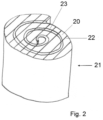
- a roll of adhesive tape 21 is shown with one of the two winding mirrors 20.
- the roll of adhesive tape 21 consists of a rolled-up adhesive tape, which in turn has a substrate web 22, onto one side of which a pressure-sensitive adhesive is applied over the entire surface as a pressure-sensitive adhesive web 23.
- the substrate web 22 can be a film, a fabric or a paper.
- the substrate web 22 and the pressure-sensitive adhesive web 23 together form the adhesive tape, which in Fig. 2 is rolled up.
- the substrate web 22 is usually manufactured and made available in widths of 500 mm to 2,000 mm and is also coated with the pressure-sensitive adhesive in this width.
- the substrate web 22 is wound up together with the pressure-sensitive adhesive web 23 formed on it, so that a wide adhesive tape roll is also created in a width of 500 mm to 2,000 mm. Only then is the wide adhesive tape roll cut into adhesive tape rolls 21 of the desired working width. After During the cutting process, the pressure-sensitive adhesive on the cut edges of the adhesive tape rolls 21, in particular the pressure-sensitive adhesive webs 23, is exposed and, due to its adhesive properties, can make further processing and product use difficult or even impossible.
- the winding mirror 20 of the Fig. 2 is characterized by an alternating sequence of substrate webs 22 and pressure-sensitive adhesive webs 23.
- the adhesive tape has a very small ratio of a thickness of the substrate web 22 to a thickness of the pressure-sensitive adhesive web 23.
- viscoelastic materials with their own adhesive properties are often used for the substrate webs 22, so that almost the entire winding surface 20 of the adhesive tape roll 21 is adhesive.
- the pressure-sensitive adhesiveness of the winding surface 20 means that after contact with other objects, the adhesive tape roll 21 is destroyed or deformed when removed or can no longer be used. This is a particular problem with narrow rolls, which have only low mechanical strength.
- the adhesive strength of the winding mirror 20 is reduced by applying a passivation layer.
- the passivation layer is a SiOx coating which is applied with the aid of the Fig. 1 shown plasma nozzle 1 is applied to the entire surface of the winding mirror 20 in a plasma process.
- the plasma nozzle 1 is at a perpendicular angle to a surface of the winding mirror 20 and opens into the nozzle head 8, wherein the winding mirror 20 rests on a rotating table, not shown.
- a plasma 7 is understood to mean an atmospheric pressure plasma, which is an electrically activated homogeneous reactive gas that is not in thermal equilibrium, with a pressure close to the ambient pressure in its effective range. In general, the pressure is 0.5 bar more than the ambient pressure.
- the process gas is 11 is activated and highly excited states are generated in the gas components.
- the precursor 4 in gaseous form or as an aerosol is then fed to the process gas 11 in the nozzle head 8 via a gas-conducting channel via the side inlet 17, which forms the actual silicon oxide layer on the surface of the winding mirror 20.
- HMDSO hexamethyldisiloxane
- the test setup includes the following parameters, conditions and technical data to be considered: Material to be treated: ACX plus - 7056 as a flap sample plasma nozzle: Generator FG 5001, fixed nozzle 216028WE Precursor: hexamethyldisiloxane (HMDSO) Precursor amount: 10, 20, 40 g/hour Number of treatments: 1- to 3-fold Treatment speed: 40 m/min for flat KM surfaces Nozzle distance: 15 mm PCT (Pulse-Cycle-Time): 20% and 100%
- the PCT value controls the glassy appearance of the silane layer.
- PCT Pulse-Cycle-Time
- Table 1 shows the tack results of untreated and treated ACX plus -7056 flap samples using the Proptec standard procedure.
- the Proptec process is a method for measuring the instant adhesive strength, i.e. the tack of an adhesive. This can be used as a quality feature for passivation and can provide a quantified value.
- tesa ® ACX plus 7056 is a transparent carrier-free acrylic adhesive tape with a foamed acrylic-based pressure-sensitive adhesive with a thickness of 1500 ⁇ m.
- One adhesive side of a cloth coated with ACX plus is coated with HMDSO, whereby the left column shows the amount of HMDSO applied per hour, the second column the speed at which the nozzle head 8 is moved over the cloth, the third column the distance of the nozzle head 8 from the cloth and PCT the above-mentioned pulse cycle time.
- Fmax indicates the maximum force required to remove the stamp pressed onto the cloth and the right column indicates the energy required for this.
- the area of the circular Proptec stamp is 25.4 mm, the stamp is pressed onto the flap with a force of 4.5 N for 1 second.
- the 'Remarks' section shows how strongly the cloth (KM) adheres to the stamp.
- the bottom line gives the reference of a cloth coated with ACX plus without a plasma-polymerized coating. It is clearly visible that there are significant reductions in the adhesive force compared to the untreated adhesive surface of the ACX plus product.
- the adhesive force is also referred to as tackiness.
- the above measurements can also be applied to the winding mirror 20 of ACX plus rolls. With the treated ACX plus rolls, it can be seen that they not only do not adhere to metal surfaces, but can also be picked up again without any problems.
- the plasma polymerization layer has a dirt-repellent function, as dust, fibers and paper hardly stick to the pressure-sensitive adhesive. Even over a period of eight hours, no noticeable contamination of the nozzle components of the plasma unit 3 by the precursor 4 could be detected.
Landscapes
- Chemical & Material Sciences (AREA)
- Engineering & Computer Science (AREA)
- Plasma & Fusion (AREA)
- Physics & Mathematics (AREA)
- Organic Chemistry (AREA)
- Metallurgy (AREA)
- Materials Engineering (AREA)
- Mechanical Engineering (AREA)
- Chemical Kinetics & Catalysis (AREA)
- General Chemical & Material Sciences (AREA)
- Analytical Chemistry (AREA)
- Inorganic Chemistry (AREA)
- Spectroscopy & Molecular Physics (AREA)
- Adhesives Or Adhesive Processes (AREA)
- Adhesive Tapes (AREA)
- Plasma Technology (AREA)
- Application Of Or Painting With Fluid Materials (AREA)
- Laminated Bodies (AREA)
Description
- Die Erfindung betrifft ein Verfahren zur Reduzierung der Wickelspiegelklebrigkeit einer Klebebandrolle sowie eine Klebebandrolle.
- Bei Klebebandrollen, insbesondere des ACXplus -Sortiments (das ACXplus -Sortiment der Firma tesa umfasst geschäumte Klebebänder mit acrylatbasierten Klebemassen), hat es sich als nachteilig herausgestellt, dass die Seitenkanten beim Stapeln oder bei Kontakt zu anderen Gegenständen zum Verkleben neigen. Um diesem unerwünschten Effekt entgegenzuwirken, werden typischerweise silikonisierte Seitenscheiben auf den Wickelspiegel der Rolle gelegt. Bei ACXplus Produkten werden pro Rolle zur Sicherheit zwei Seitenscheiben eingesetzt, bei filmic-Produkten (übliche Klebebänder mit einer Folie als Träger auf die eine Klebemasse aufgebracht ist) reicht nur eine Seitenscheibe. Selbige verhindern gleichzeitig eine Verschmutzung durch Partikel, die sich bei Transport oder Verarbeitung an den Haftklebstoff binden. Bei Einsatz entsprechender Seitenscheiben müssen diese passend auf Rollenmaß und Verpackung konfektioniert sein. Für eine maschinelle sowie manuelle Verarbeitung ist die Seitenscheibe anschließend zu entfernen, nach Gebrauch wiederum auf den Wickelspiegel zu legen. Insgesamt bedeutet die Nutzung silikonisierter Seiteneinleger einen nicht unerheblichen Arbeitsaufwand.
- Es existieren bereits verschiedene Lösungen für die Deaktivierung der Seitenkantenklebrigkeit.
- Über eine Druckpuderbestäubung wird die Seitenkante behandelt, so dass aufgetragenes Talkum oder aufgetragene Glaskugeln zu einer Reduzierung der Klebkraft führen. Nachteilig wirkt sich dieses Verfahren auf die optischen Eigenschaften der Klebebandrolle aus. Zudem kommt es zu Kontamination von wenig fest haftenden Talkumpartikeln, was in zahlreichen Anwendungen unerwünscht ist. Eine Langzeitstabilität der Deaktivierung ist gleichzeitig nicht gegeben, da die aufgebrachten Partikel bei höheren Temperaturen in die Klebmasse einsinken bzw. von dieser umflossen werden.
- Als weitere Lösung wird die Beschichtung der Seitenkante mit einem konventionellen Lack vorgenommen. Hier sind Prozesszeiten aufgrund der notwendigen Trocknung sehr lang. Gleichzeitig beobachtet man für große Auftragsmengen von z. B. 3 g/m2 höhere Abrollkräfte. Durch Zugabe von Wasser in den Lack vermindert man die Filmbildung, so dass die Abrollkräfte auf normales Niveau reduziert werden können.
- Aus der
WO 2008/095653 A1 ist ein Verfahren zur Passivierung einer Kante von Haftklebebändern beschrieben, wobei die Passivierung durch physikalische oder chemische Vernetzung des Haftklebers auf der Kante oder durch den physikalischen oder chemischen Abbau der für die haftklebende Wirkung verantwortlichen Strukturen des Haftklebers erfolgt. Das wird durch Auftragen eines Vernetzers auf die Seitenkante mit nachträglicher UV- oder IR-Bestrahlung, Elektronenbestrahlung, Gammabestrahlung oder Plasmabehandlung erzielt. Als Vernetzer werden unter anderem Epoxide, Amine, Isocyanate, Peroxide oder polyfunktionelle Silane offenbart. Nachteilig ist der relativ umständliche und aufwändige Aufbau des Verfahrens. - In der
EP 1 373 423 ist ein Verfahren zum Deaktivieren der Klebeschicht der Kantenfläche einer Klebebandrolle beschrieben, bei dem strahlenchemisch vernetzbare Acrylate, Acrylatoligomere und Acrylatprepolymere aufgetragen werden und mit ionisierender und elektromagnetischer Strahlung ausgehärtet werden. - In der
US 2010/004 47 530 - In der
EP 1 129 791 A2 ist ein Verfahren zur Herstellung von antiadhäsiven Beschichtungen beschrieben, bei denen die antiadhäsive Schicht mittels Niederdruckplasmapolymerisation auf das bahnförmige Material aufgebracht wird, indem das bahnförmige Material kontinuierlich durch eine Plasmazone gezogen geführt wird, in der ein Niederdruckplasma vorhanden ist. Die mittels Plasmapolymerisation geformten antiadhäsiven Beschichtungen sind insbesondere für Klebebandrückseiten und Trennmaterialien hergestellt. - Die oben genannten Verfahren eignen sich nur bedingt zur Reduzierung der Haftklebrigkeit des Wickelspiegels einer Klebebandrolle.
- Die
WO 2013/039737 A2 beschreibt ein Verfahren zum Reduzieren der Klebrigkeit einer Kantenfläche eines gerollten Substrats wie eine Klebebandrolle. Das Reduzieren der Klebrigkeit erfolgt unter Einsatz einer Strahlungsquelle mit einer Strahlungsleistung bei einer Wellenlänge von weniger als 200 Nanometern. - Es ist daher Aufgabe der Erfindung, ein verbessertes Verfahren zur Verfügung zu stellen, das die Haftklebrigkeit des Wickelspiegels einer Klebebandrolle reduziert, und es ist Aufgabe der Erfindung, eine Klebebandrolle mit reduzierter Haftklebrigkeit zur Verfügung zu stellen.
- Hinsichtlich des Verfahrens wird die Aufgabe durch ein Verfahren mit den Merkmalen des Anspruchs 1 gelöst.
- Erfindungsgemäß wird einem Atmosphärendruck-Plasmastrom ein organische polyfunktionelle Silane aufweisender Precursor zugeführt. Der mit dem Precursor angereicherte Plasmastrom wird auf einen Wickelspiegel gerichtet und der Wickelspiegel mit einer SiOx-Beschichtung überzogen. Günstigerweise wird der mit dem Precursor angereicherte Plasmastrom direkt auf den Wickelspiegel gerichtet, so dass der Wickelspiegel unmittelbar und direkt mit einer SiOx-Beschichtung überzogen wird.
- Es hat sich überraschend gezeigt, dass ein Plasmabeschichtungsverfahren direkt auf den Wickelspiegel einer Klebebandrolle angewendet werden kann. Bei der Klebebandrolle handelt es sich um ein aufgewickeltes Klebeband, dessen Länge deutlich größer als dessen Breite und dessen Breite wiederum deutlich größer als dessen Dicke ist. Das Klebeband besteht in seiner einfachsten Ausführungsform aus einer einzigen, insbesondere geschäumten Klebemassenschicht. Das Klebeband weist weiterhin zumindest eine Substratbahn auf und eine auf die Substratbahn aufgebrachte Haftklebebahn. Es ist natürlich auch möglich, dass zwischen der Substrat- und der Haftklebebahn weitere Bahnen bzw. Schichten vorgesehen sind. Für die Erfindung wesentlich ist jedoch, dass beim Aufwickeln des Klebebandes auf eine Klebebandrolle die Schmalseiten der Haftklebebahn zwischen den Substratbahnen freiliegen und an anderen Gegenständen anhaften können oder Schmutz aufnehmen können. Die Stirnseite der Abfolge aufgewickelter Substratbahnen und Haftklebebahnen, die alternierend sein kann, wird als Wickelspiegel bezeichnet. Auf den Wickelspiegel wird vorzugsweise vollflächig die SiOx-Beschichtung aufgebracht. Günstigerweise ist die Beschichtung über die gesamte Ausdehnung des Wickelspiegels von konstanter Dicke. Vorzugsweise ist die Beschichtung zwischen 60 nm bis 600 nm dick, vorzugsweise liegt die Dicke zwischen 100 nm und 200 nm.
- Vorzugsweise werden Klebebandrollen hergestellt, indem zunächst eine sehr breite Klebebandrolle produziert wird mit Breiten bis zu 2.000 mm, und diese breite Klebebandrolle wird dann in Klebebandrollen geschnitten. Die geschnittenen Klebebandrollen sind an ihren Wickelspiegeln besonders klebrig.
- In einer Weiterbildung der Erfindung wird eine Mutterrolle quer zur Längsachse in separate Klebebandrollen zerschnitten, und die Wickelspiegel der separaten Klebebandrollen werden zunächst mit der SiOx-Beschichtung passiviert. Eine, zwei oder jede höhere Anzahl der Klebebandrollen kann dann sogar wieder jeweils abgewickelt und traversierend neu aufgewickelt werden. Bei dem traversierenden Aufwickeln handelt es sich zunächst um ein Abwickeln eines schmalen Klebebandes von einer genauso schmalen Klebebandrolle, wobei das schmale Klebeband dann auf eine deutlich längere Wickelachse traversierend aufgewickelt wird, so dass die Klebebandlagen nicht nur direkt aufeinander zum Liegen kommen, sondern zunächst nebeneinander entlang der Wickelachse aufgewickelt werden, bis eine erste Wickellage aufgewickelt ist, und dann eine zweite Wickellage in entgegengesetzter Richtung auf der Wickelachse aufgewickelt wird.
- Die Erfindung wird hinsichtlich der Klebebandrolle durch eine Klebebandrolle mit den Merkmalen des Anspruchs 7 erfüllt.
- Die Klebebandrolle wird vorzugsweise durch eines der oben genannten Verfahren hergestellt und zeichnet sich durch wenigstens einen, vorzugsweise genau zwei Wickelspiegel aus, auf die vollflächig eine SiOx-Beschichtung günstigerweise in einem Plasmaverfahren aufgebracht ist. Die SiOx-Beschichtung kann eine Dicke von 60 nm bis 600 nm, vorzugsweise zwischen 100 nm und 200 nm aufweisen, und sie ist vorzugsweise über die gesamte Ausdehnung des Wickelspiegels in konstanter Schichtdicke aufgebracht.
- Bei den Klebebandrollen handelt es sich insbesondere um solche des ACXplus -Sortiments der Firma tesa.
- Derartige Klebebänder umfassen eine Trägerschicht, die auch als Hartphase bezeichnet wird. Die Polymerbasis der Hartphase ist bevorzugt ausgewählt aus der Gruppe bestehend aus Polyvinylchloriden (PVC), Polyethylenterephthalaten (PET), Polyurethanen, Polyolefinen, Polybutylenterephthalaten (PBT), Polycarbonaten, Polymethylmethacrylaten (PMMA), Polyvinylbutyralen (PVB), lonomeren und Mischungen aus zwei oder mehreren der vorstehend aufgeführten Polymere. Besonders bevorzugt ist die Polymerbasis der Hartphase ausgewählt aus der Gruppe bestehend aus Polyvinylchloriden, Polyethylenterephthalaten, Polyurethanen, Polyolefinen und Mischungen aus zwei oder mehreren der vorstehend aufgeführten Polymere. Die Hartphase ist im Wesentlichen eine Polymerfolie, deren Polymerbasis aus den vorstehenden Materialien ausgewählt ist. Unter einer "Polymerfolie" wird eine dünne, flächige, flexible, aufwickelbare Bahn verstanden, deren Materialbasis im Wesentlichen von einem oder mehreren Polymer(en) gebildet wird.
- Unter "Polyurethanen" werden in weitgefasstem Sinne polymere Substanzen verstanden, in denen sich wiederholende Einheiten durch Urethan-Gruppierungen -NH-CO-O-miteinander verknüpft sind.
- Unter "Polyolefinen" werden Polymere verstanden, die stoffmengenbezogen zu mindestens 50% Wiederholungseinheiten der allgemeinen Struktur -[-CH2-CR1 R2-]n-enthalten, worin R1 für ein Wasserstoffatom und R2 für ein Wasserstoffatom oder für eine lineare oder verzweigte, gesättigte aliphatische oder cycloaliphatische Gruppe steht. Soweit die Polymerbasis der Hartphase Polyolefine umfasst, handelt es sich bei diesen besonders bevorzugt um Polyethylene, insbesondere um Polyethylene mit ultrahoher Molmasse (UHMWPE).
- Unter der "Polymerbasis" wird das Polymer beziehungsweise werden die Polymere verstanden, das/die den größten Gewichtsanteil aller in der betreffenden Schicht beziehungsweise Phase enthaltenen Polymere ausmacht/ausmachen.
- Die Dicke der Hartphase beträgt insbesondere ≤ 150 µm. Bevorzugt beträgt die Dicke der Hartphase 10 bis 150 µm, besonders bevorzugt 30 bis 120 µm und insbesondere 50 bis 100 µm, beispielsweise 70 bis 85 µm. Unter der "Dicke" wird die Ausdehnung der betreffenden Schicht beziehungsweise Phase entlang der z-Ordinate eines gedachten Koordinatensystems verstanden, bei dem die durch die Maschinenrichtung und die Querrichtung zur Maschinenrichtung aufgespannte Ebene die x-y-Ebene bildet. Die Dicke wird durch Messung an mindestens fünf verschiedenen Stellen der betreffenden Schicht beziehungsweise Phase und anschließende Bildung des arithmetischen Mittels aus den erhaltenen Messergebnissen ermittelt. Die Dickenmessung der Hartphase erfolgt dabei in Einklang mit DIN EN ISO 4593.
- Derartige Klebebänder können weiterhin eine Weichphase aufweisen, die einen Polymerschaum, eine viskoelastische Masse und/oder eine elastomere Masse umfassen. Die Polymerbasis der Weichphase ist bevorzugt ausgewählt aus Polyolefinen, Polyacrylaten, Polyurethanen und Mischungen aus zwei oder mehreren der vorstehend aufgeführten Polymere.
- In der einfachsten Variante besteht das Klebeband nur aus einer Weichphase.
- Unter einem "Polymerschaum" wird ein Gebilde aus gasgefüllten kugel- oder polyederförmigen Zellen verstanden, welche durch flüssige, halbflüssige, hochviskose oder feste Zellstege begrenzt werden; ferner ist der Hauptbestandteil der Zellstege ein Polymer oder ein Gemisch mehrerer Polymere.
- Unter einer "viskoelastischen Masse" wird ein Material verstanden, das neben Merkmalen der reinen Elastizität (Zurückkehren in den Ausgangszustand nach äußerer mechanischer Einwirkung) auch Merkmale einer viskosen Flüssigkeit zeigt, beispielsweise das Auftraten innerer Reibung bei Deformation. Insbesondere werden Haftklebemassen auf Polymerbasis als viskoelastische Massen angesehen.
- Unter einer "elastomeren Masse" wird ein Material verstanden, das gummielastisches Verhalten aufweist und bei 20°C wiederholt auf mindestens das Zweifache seiner Länge gedehnt werden kann und nach Aufhebung des für die Dehnung erforderlichen Zwanges sofort wieder annähernd seine Ausgangsdimension einnimmt.
- Bezüglich des Verständnisses der Begriffe "Polymerbasis", "Polyurethane" und "Polyolefine" gilt das oben Gesagte. Unter "Polyacrylaten" werden Polymere verstanden, deren stoffmengenbezogene Monomerbasis zu mindestens 50% aus Acrylsäure, Methacrylsäure, Acrylsäureestern und/oder Methacrylsäureestern besteht, wobei Acrylsäureester und/oder Methacrylsäureester zumindest anteilig generell und bevorzugt zu mindestens 50% enthalten sind. Insbesondere wird unter einem "Polyacrylat" ein Polymerisat verstanden, welches durch radikalische Polymerisation von Acryl- und/oder Methylacrylmonomeren sowie gegebenenfalls weiteren, copolymerisierbaren Monomeren erhältlich ist.
- Besonders bevorzugt ist die Polymerbasis der Weichphase ausgewählt aus Polyolefinen, Polyacrylaten und Mischungen aus zwei oder mehreren der vorstehend aufgeführten Polymere. Sofern Polyolefine zu der Polymerbasis der Weichphase gehören, sind diese bevorzugt ausgewählt aus Polyethylenen, Ethylen-Vinylacetat-Copolymeren (EVA) und Gemischen aus Polyethylenen und Ethylen-Vinylacetat-Copolymeren (PE/EVA-Blends). Die Polyethylene können dabei verschiedene Polyethylen-Typen sein, beispielsweise HDPE, LDPE, LLDPE, Blends aus diesen Polyethylen-Typen und/oder Gemische davon.
- In einer Ausführungsform umfasst die Weichphase einen Schaum und jeweils eine ober- und unterhalb der geschäumten Schicht angeordnete Haftklebeschicht, wobei die Polymerbasis des Schaums aus einem oder mehreren Polyolefin(en) besteht und die Polymerbasis der Haftklebeschichten aus einem oder mehreren Polyacrylat(en) besteht. Besonders bevorzugt besteht die Polymerbasis des Schaums dabei aus einem oder mehreren Polyethylen(en), Ethylen-Vinylacetat-Copolymer(en) und Gemischen aus einem oder mehreren Polyethylen(en) und/oder Ethylen-Vinylacetat-Copolymer(en). Ganz besonders bevorzugt besteht die Polymerbasis des Schaums dabei aus einem oder mehreren Polyethylen(en).
- Der Polyolefin-basierte Schaum selbst ist nicht oder nur sehr wenig haftklebrig. Der Verbund mit der Hartphase beziehungsweise dem Substrat wird daher vorteilhaft durch die Haftklebeschichten bewirkt. Die Schäumung des Polyolefin-basierten Ausgangsmaterials des Schaums wird bevorzugt durch zugesetztes Treibgas im Sinne einer physikalischen Schäumung und/oder durch ein chemisches Schäumungsmittel, beispielsweise durch Azodicarbonsäurediamin, hervorgerufen.
- In einer weiteren Ausführungsform ist die Weichphase ein haftklebriger Polymerschaum, dessen Polymerbasis aus einem oder mehreren Polyacrylaten besteht. "Haftklebriger Schaum" bedeutet, dass der Schaum selbst eine Haftklebemasse ist und somit ein Auftrag einer zusätzlichen Haftklebeschicht nicht erforderlich ist. Dies ist vorteilhaft, weil im Herstellungsprozess weniger Schichten zusammengefügt werden müssen und das Risiko von Ablösungserscheinungen und anderen unerwünschten Phänomenen an den Schichtgrenzen sinkt.
- Unter einer "Haftklebemasse" wird ein Material verstanden, dessen abgebundener Film bei Raumtemperatur in trockenem Zustand permanent klebrig und klebfähig bleibt, wobei eine Verklebung durch leichten Anpressdruck sofort auf einer Vielzahl unterschiedlicher Substrate erfolgt.
- Die Polyacrylate sind bevorzugt erhältlich durch zumindest anteiliges Einpolymerisieren von funktionellen, mit Epoxidgruppen vernetzungsfähigen Monomeren. Besonders bevorzugt handelt es sich dabei um Monomere mit Säuregruppen (besonders Carbonsäure-, Sulfonsäure oder Phosphonsäuregruppen) und/oder Hydroxygruppen und/oder Säureanhydridgruppen und/oder Epoxidgruppen und/oder Amingruppen; insbesondere bevorzugt sind carbonsäuregruppenhaltige Monomere. Es ist ganz besonders vorteilhaft, wenn die Polyacrylate einpolymerisierte Acrylsäure und/oder Methacrylsäure aufweisen. All diese Gruppen weisen eine Vernetzungsfähigkeit mit Epoxidgruppen auf, wodurch die Polyacrylate vorteilhaft einer thermischen Vernetzung mit eingebrachten Epoxiden zugänglich wird.
- Weitere Monomere, die als Comonomere für die Polyacrylate verwendet werden können, sind neben Acrylsäure- und/oder Methacrylsäureestern mit bis zu 30 C-Atomen beispielsweise Vinylester von bis zu 20 C-Atome enthaltenden Carbonsäuren, Vinylaromaten mit bis zu 20 C-Atomen, ethylenisch ungesättigte Nitrile, Vinylhalogenide, Vinylether von 1 bis 10 C-Atome enthaltenden Alkoholen, aliphatische Kohlenwasserstoffe mit 2 bis 8 C-Atomen und 1 oder 2 Doppelbindungen oder Mischungen dieser Monomeren.
- Die Eigenschaften des betreffenden Polyacrylats lassen sich insbesondere über eine Variation der Glasübergangstemperatur des Polymers durch unterschiedliche Gewichtsanteile der einzelnen Monomere beeinflussen. Die Polyacrylate können vorzugsweise auf die folgende Monomerzusammensetzung zurückgeführt werden:
- a) Acrylsäureester und/oder Methacrylsäureester der folgenden Formel
CH2 = C(RI)(COORII)
wobei RI = H oder CH3 und RII ein Alkylrest mit 4 bis 14 C-Atomen ist, - b) olefinisch ungesättigte Monomere mit funktionellen Gruppen der für eine Reaktivität mit Epoxidgruppen bereits definierten Art,
- c) optional weitere Acrylate und/oder Methacrylate und/oder olefinisch ungesättigte Monomere, die mit der Komponente (a) copolymerisierbar sind.
- Bevorzugt beruhen die Polyacrylate auf einer Monomerenzusammensetzung, in der die Monomere der Komponente (a) mit einem Anteil von 45 bis 99 Gew.-%, die Monomere der Komponente (b) mit einem Anteil von 1 bis 15 Gew.-% und die Monomere der Komponente (c) mit einem Anteil von 0 bis 40 Gew.-% enthalten sind (die Angaben sind bezogen auf die Monomermischung für das "Basispolymer", also ohne Zusätze eventueller Additive zu dem fertigen Polymer, wie Harze etc.). In diesem Fall weist das Polymerisationsprodukt eine Glastemperatur ≤ 15 °C (DMA bei geringen Frequenzen) und haftklebende Eigenschaften auf.
- Die Monomere der Komponente (a) sind insbesondere weichmachende und/oder unpolare Monomere. Vorzugsweise werden als Monomere (a) Acryl- und Methacrylsäureester mit Alkylgruppen bestehend aus 4 bis 14 C-Atomen, besonders bevorzugt 4 bis 9 C-Atomen, eingesetzt. Beispiele für derartige Monomere sind n-Butylacrylat, n-Butylmethacrylat, n-Pentylacrylat, n-Pentylmethacrylat, n-Amylacrylat, n-Hexylacrylat, n-Hexylmethacrylat, n-Heptylacrylat, n-Octylacrylat, n-Octylmethacrylat, n-Nonylacrylat, Isobutylacrylat, Isooctylacrylat, Isooctylmethacrylat, und deren verzweigte Isomere, wie zum Beispiel 2 Ethylhexylacrylat oder 2 Ethylhexylmethacrylat.
- Die Monomere der Komponente (b) sind insbesondere olefinisch ungesättigte Monomere mit funktionellen Gruppen, insbesondere mit funktionellen Gruppen, die eine Reaktion mit Epoxidgruppen eingehen können.
- Bevorzugt werden für die Komponente (b) Monomere mit funktionellen Gruppen eingesetzt, die ausgewählt sind aus der Gruppe umfassend: Hydroxy-, Carboxy-, Sulfonsäure- oder Phosphonsäuregruppen, Säureanhydride, Epoxide, Amine. Besonders bevorzugte Beispiele für Monomere der Komponente (b) sind Acrylsäure, Methacrylsäure, Itaconsäure, Maleinsäure, Fumarsäure, Crotonsäure, Aconitsäure, Dimethylacrylsäure, β-Acryloyloxypropionsäure, Trichloracrylsäure, Vinylessigsäure, Vinylphosphonsäure, Itaconsäure, Maleinsäureanhydrid, Hydroxyethylacrylat, Hydroxypropylacrylat, Hydroxyethylmethacrylat, Hydroxypropylmethacrylat, 6-Hydroxyhexylmethacrylat, Allylalkohol, Glycidylacrylat, Glycidylmethacrylat.
- Prinzipiell können als Komponente (c) alle vinylisch funktionalisierten Verbindungen eingesetzt werden, die mit der Komponente (a) und/oder der Komponente (b) copolymerisierbar sind. Die Monomere der Komponente (c) können zur Einstellung der Eigenschaften der resultierenden Haftklebemasse dienen.
- Methylacrylat, Ethylacrylat, Propylacrylat, Methylmethacrylat, Ethylmethacrylat, Benzylacrylat, Benzylmethacrylat, sec-Butylacrylat, tert-Butylacrylat, Phenylacrylat, Phenylmethacrylat, Isobornylacrylat, Isobornylmethacrylat, tert-Butylphenylacrylat, tert-Butylaphenylmethacrylat, Dodecylmethacrylat, Isodecylacrylat, Laurylacrylat, n-Undecylacrylat, Stearylacrylat, Tridecylacrylat, Behenylacrylat, Cyclohexylmethacrylat, Cyclopentylmethacrylat, Phenoxyethylacrlylat, Phenoxyethylmethacrylat, 2-Butoxyethylmethacrylat, 2-Butoxyethylacrylat, 3,3,5-Trimethylcyclohexylacrylat, 3,5-Dimethyladamantylacrylat, 4-Cumylphenylmethacrylat, Cyanoethylacrylat, Cyanoethylmethacrylat, 4-Biphenylacrylat, 4-Biphenylmethacrylat, 2-Naphthylacrylat, 2-Naphthylmethacrylat, Tetrahydrofufurylacrylat, Diethylaminoethylacrylat, Diethylaminoethylmethacrylat, Dimethylaminoethyl-acrylat, Dimethylaminoethylmethacrylat, 2-Butoxyethylacrylat, 2-Butoxy¬ethylmethacrylat, 3-Methoxyacrylsäuremethylester, 3-Methoxybutylacrylat, Phenoxyethylacrlylat, Phenoxyethylmethacrylat, 2-Phenoxyethylmethacrylat, Butyldiglykolmethacrylat, Ethylenglycolacrylat, Ethylenglycolmonomethylacrylat, Methoxy Polyethylenglykolmethacrylat 350, Methoxy Polyethylenglykolmethacrylat 500, Propylenglycolmonomethacrylat, Butoxydiethylenglykolmethacrylat, Ethoxytriethylenglykolmethacrylat, Octafluoropentylacrylat, Octafluoropentylmethacrylat, 2,2,2-Trifluoroethylmethacrylat, 1,1,1,3,3,3-Hexafluoroisopropylacrylat, 1,1,1,3,3,3-Hexafluoroisopropylmethacrylat, 2,2,3,3,3-Pentafluoropropylmethacrylat, 2,2,3,4,4,4-Hexafluorobutylmethacrylat, 2,2,3,3,4,4,4-Heptafluorobutylacrylat, 2,2,3,3,4,4,4-Heptafluorobutylmethacrylat, 2,2,3,3,4,4,5,5,6,6,7,7,8,8,8-Pentadecafluorooctylmethacrylat, Dimethylaminopropylacrylamid, Dimethylaminopropylmethacrylamid, N-(1-Methylundecyl)acrylamid, N-(n-Butoxymethyl)acrylamid, N-(Butoxymethyl)methacrylamid, N-(Ethoxymethyl)acrylamid, N-(n-Octadecyl)acrylamid, weiterhin N,N-Dialkyl-substituierte Amide, wie beispielsweise N,N-Dimethylacrylamid, N,N-Dimethylmethacrylamid, N-Benzyl-acrylamide, N-Isopropylacrylamid, N-tert-Butylacrylamid, N-tert-Octylacrylamid, N-Methylolacrylamid, N-Methylolmethacrylamid, Acrylnitril, Methacrylnitril, Vinylether, wie Vinylmethylether, Ethylvinylether, Vinylisobutylether, Vinylester, wie Vinylacetat, Vinylchlorid, Vinylhalogenide, Vinylidenchlorid, Vinylidenhalogenide, Vinylpyridin, 4-Vinylpyridin, N-Vinylphthalimid, N-Vinyllactam, N-Vinylpyrrolidon, Styrol, a- und p-Methylstyrol, a-Butylstyrol, 4-n-Butylstyrol, 4-n-Decylstyrol, 3,4-Dimethoxystyrol. Makromonomere wie 2-Polystyrolethylmethacrylat (Molekulargewicht Mw von 4000 bis 13000 g/mol), Poly(methylmethacrylat)ethylmethacrylat (Mw von 2000 bis 8000 g/mol).
- Monomere der Komponente (c) können vorteilhaft auch derart gewählt werden, dass sie funktionelle Gruppen enthalten, die eine nachfolgende strahlenchemische Vernetzung (beispielsweise durch Elektronenstrahlen, UV) unterstützen. Geeignete copolymerisierbare Photoinitiatoren sind zum Beispiel Benzoinacrylat und acrylatfunktionalisierte Benzophenonderivate. Monomere, die eine Vernetzung durch Elektronenbestrahlung unterstützen, sind zum Beispiel Tetrahydrofufurylacrylat, N-tert-Butylacrylamid und Allylacrylat.
- Die Herstellung der Polyacrylate ("Polyacrylate" wird im Rahmen der Erfindung als synonym mit "Poly(meth)acrylate" verstanden) kann nach dem Fachmann geläufigen Verfahren geschehen, insbesondere vorteilhaft durch konventionelle radikalische Polymerisationen oder kontrollierte radikalische Polymerisationen. Die Polyacrylate können durch Copolymerisation der monomeren Komponenten unter Verwendung der üblichen Polymerisationsinitiatoren sowie gegebenenfalls von Reglern hergestellt werden, wobei bei den üblichen Temperaturen in Substanz, in Emulsion, zum Beispiel in Wasser oder flüssigen Kohlenwasserstoffen, oder in Lösung polymerisiert wird.
- Vorzugsweise werden die Polyacrylate durch Polymerisation der Monomere in Lösungsmitteln, insbesondere in Lösungsmitteln mit einem Siedebereich von 50 bis 150 °C, vorzugsweise von 60 bis 120 °C unter Verwendung der üblichen Mengen an Polymerisationsinitiatoren, die im allgemeinen bei 0,01 bis 5, insbesondere bei 0,1 bis 2 Gew.-% (bezogen auf das Gesamtgewicht der Monomeren) liegen, hergestellt.
- Prinzipiell eignen sich alle dem Fachmann geläufigen, üblichen Initiatoren. Beispiele für Radikalquellen sind Peroxide, Hydroperoxide und Azoverbindungen, zum Beispiel Dibenzoylperoxid, Cumolhydroperoxid, Cyclohexanonperoxid, Di-t-butylperoxid, Cyclohexylsulfonylacetylperoxid, Diisopropylpercarbonat, t-Butylperoktoat, Benzpinacol. In einer sehr bevorzugten Vorgehensweise wird als radikalischer Initiator 2,2'-Azobis(2-methylbutyronitril) (Vazo® 67™ der Firma DuPont) oder 2,2'-Azobis(2-methylpropionitril) (2,2'-Azobisisobutyronitril; AIBN; Vazo® 64™ der Firma DuPont) verwendet.
- Als Lösungsmittel für die Herstellung der Polyacrylate kommen Alkohole wie Methanol, Ethanol, n-und iso-Propanol, n-und iso-Butanol, vorzugsweise Isopropanol und/oder Isobutanol, sowie Kohlenwasserstoffe wie Toluol und insbesondere Benzine eines Siedebereichs von 60 bis 120 °C in Frage. Ferner können Ketone wie vorzugsweise Aceton, Methylethylketon, Methylisobutylketon und Ester wie Essigsäureethylester sowie Gemische von Lösungsmitteln der genannten Art eingesetzt werden, wobei Gemische, die Isopropanol, insbesondere in Mengen von 2 bis 15 Gew.-%, bevorzugt 3 bis 10 Gew.-%, bezogen auf das eingesetzte Lösungsmittelgemisch, enthalten, vorgezogen werden.
- Bevorzugt erfolgt nach der Herstellung (Polymerisation) der Polyacrylate eine Aufkonzentration, und die weitere Verarbeitung der Polyacrylate erfolgt im Wesentlichen lösemittelfrei. Die Aufkonzentration des Polymerisats kann in Abwesenheit von Vernetzer- und Beschleunigersubstanzen geschehen. Es ist aber auch möglich, eine dieser Verbindungsklassen dem Polymerisat bereits vor der Aufkonzentration zuzusetzen, so dass die Aufkonzentration dann in Gegenwart dieser Substanz(en) erfolgt.
- Die Polymerisate können nach dem Aufkonzentrationsschritt in einen Compounder überführt werden. Gegebenenfalls können die Aufkonzentration und die Compoundierung auch im selben Reaktor stattfinden.
- Die gewichtsmittleren Molekulargewichte MW der Polyacrylate liegen bevorzugt in einem Bereich von 20.000 bis 2.000.000 g/mol; sehr bevorzugt in einem Bereich von 100.000 bis 1.000.000 g/mol, äußerst bevorzugt in einem Bereich von 150.000 bis 500.000 g/mol (die Angaben des mittleren Molekulargewichtes MW und der Polydisperistät PD in dieser Schrift beziehen sich auf die Bestimmung per Gelpermeationschromatographie. Als Eluent wurde THF mit 0,1 Vol.-% Trifluoressigsäure eingesetzt. Die Messung erfolgte bei 25 °C. Als Vorsäule wurde PSS-SDV, 5 µm, 103 Ä, ID 8,0 mm × 50 mm verwendet. Zur Auftrennung wurden die Säulen PSS-SDV, 5 µm, 103 Ä, 105 Ä und 106 Ä mit jeweils ID 8,0 mm × 300 mm eingesetzt. Die Probenkonzentration betrug 4 g/l, die Durchflussmenge 1,0 ml pro Minute. Es wurde gegen PMMA-Standards gemessen.
- Das gewichtsmittlere Molekulargewicht Mw wird dabei mittels Gelpermeationschromatographie (GPC) bestimmt. Als Eluent wird THF mit 0,1 Vol.-% Trifluoressigsäure eingesetzt. Die Messung erfolgt bei 25 °C. Als Vorsäule wird PSS-SDV, 5 µ, 103 Ä, ID 8,0 mm × 50 mm verwendet. Zur Auftrennung werden die Säulen PSS-SDV, 5 µ, 103 Ä sowie 105 Å und 106 Å mit jeweils ID 8,0 mm × 300 mm eingesetzt. Die Probenkonzentration beträgt 4 g/l, die Durchflussmenge 1,0 ml pro Minute. Es wird gegen PMMA Standards gemessen. (µ = µm; 1 Å = 10-10 m).). Dazu kann es vorteilhaft sein, die Polymerisation in Gegenwart geeigneter Polymerisationsregler wie Thiole, Halogenverbindungen und/oder Alkohole durchzuführen, um das gewünschte mittlere Molekulargewicht einzustellen).
- Das Polyacrylat hat vorzugsweise einen K-Wert von 30 bis 90, besonders bevorzugt von 40 bis 70, gemessen in Toluol (1%ige Lösung, 21 °C). Der K-Wert nach Fikentscher ist ein Maß für das Molekulargewicht und die Viskosität des Polymerisats.
- Besonders geeignet sind Polyacrylate, die eine enge Molekulargewichtsverteilung (Polydispersität PD < 4) haben. Diese Massen haben trotz eines relativ niedrigen Molekulargewichts nach dem Vernetzen eine besonders gute Scherfestigkeit. Zudem ermöglicht die niedrigere Polydispersität eine leichtere Verarbeitung aus der Schmelze, da die Fließviskosität gegenüber einem breiter verteilten Polyacrylat bei weitgehend gleichen Anwendungseigenschaften geringer ist. Eng verteilte Poly(meth)acrylate können vorteilhaft durch anionische Polymerisation oder durch kontrollierte radikalische Polymerisationsmethoden hergestellt werden, wobei letzteres besonders gut geeignet ist. Beispiele für derartige Polyacrylate, die nach dem RAFT-Verfahren hergestellt werden, sind in der
US 6,765,078 B2 undUS 6,720,399 B2 beschrieben. Auch über N-Oxyle lassen sich entsprechende Polyacrylate herstellen, wie beispielsweise in derEP 1 311 555 B1 beschrieben ist. Auch die Atom Transfer Radical Polymerization (ATRP) lässt sich in vorteilhafter Weise zur Synthese eng verteilter Polyacrylate einsetzen, wobei als Initiator bevorzugt monofunktionelle oder difunktionelle sekundäre oder tertiäre Halogenide und zur Abstraktion des(r) Halogenids(e) Cu-, Ni-, Fe-, Pd-, Pt-, Ru-, Os-, Rh-, Co-, Ir-, Ag- oder Au-Komplexe eingesetzt werden. Die unterschiedlichen Möglichkeiten der ATRP sind in den SchriftenUS 5,945,491 A ,US 5,854,364 A undUS 5,789,487 A beschrieben. - Die Monomere zur Herstellung der Polyacrylate enthalten bevorzugt anteilig funktionelle Gruppen, die geeignet sind, mit Epoxidgruppen Verknüpfungsreaktionen einzugehen. Dies ermöglicht vorteilhaft eine thermische Vernetzung der Polyacrylate durch Reaktion mit Epoxiden. Unter Verknüpfungsreaktionen werden insbesondere Additions- und Substitutionsreaktionen verstanden. Bevorzugt kommt es also zu einer Verknüpfung der die funktionellen Gruppen tragenden Bausteine mit Epoxidgruppen tragenden Bausteinen, insbesondere im Sinne einer Vernetzung der die funktionellen Gruppen tragenden Polymerbausteine über Epoxidgruppen tragende Vernetzermoleküle als Verknüpfungsbrücken. Bei den epoxidgruppenhaltigen Substanzen handelt es sich bevorzugt um multifunktionelle Epoxide, also solche mit mindestens zwei Epoxidgruppen; entsprechend kommt es bevorzugt insgesamt zu einer mittelbaren Verknüpfung der die funktionellen Gruppen tragenden Bausteine.
- Das Polyacrylat beziehungsweise die Polyacrylate sind bevorzugt durch Verknüpfungsreaktionen - insbesondere im Sinne von Additions- oder Substitutionsreaktionen - von in ihnen enthaltenen funktionellen Gruppen mit thermischen Vernetzern vernetzt. Es können alle thermischen Vernetzer verwendet werden, die sowohl eine ausreichend lange Verarbeitungszeit gewährleisten, sodass es nicht zu einer Vergelung während des Verarbeitungsprozesses kommt, als auch zu einer schnellen Nachvernetzung des Polymers auf den gewünschten Vernetzungsgrad bei niedrigeren Temperaturen als der Verarbeitungstemperatur, insbesondere bei Raumtemperatur, führen. Möglich ist beispielsweise eine Kombination aus Carboxyl-, Amin- und/oder Hydroxygruppen enthaltenden Polymeren und Isocyanten als Vernetzer, insbesondere den in der
EP 1 791 922 A1 beschriebenen aliphatischen oder mit Aminen deaktivierten trimerisierten Isocyanaten. - Geeignete Isocyanate sind insbesondere trimerisierte Derivate von MDI [4,4-Methylen-di(phenylisocyanat)], HDI [Hexamethylendiisocyanat, 1,6-Hexylendiisocyanat] und/oder IPDI [Isophorondiisocyanat, 5-Isocyanato-1-isocyanatomethyl-1,3,3-trimethylcyclohexan], beispielsweise die Typen Desmodur® N3600 und XP2410 (jeweils BAYER AG: Aliphatische Polyisocyanate, niedrigviskose HDI-Trimerisate). Ebenfalls geeignet ist die oberflächendeaktivierte Dispersion von mikronisiertem trimerisiertem IPDI BUEJ 339®, jetzt HF9 ® (BAYER AG).
- Grundsätzlich zur Vernetzung geeignet sind aber auch andere Isocyanate wie Desmodur VL 50 (Polyisocyanate am MDI-Basis, Bayer AG), Basonat F200WD (aliphatisches Polyisocyanat, BASF AG), Basonat HW100 (wasseremulgierbares polyfunktionelles Isocyanat auf HDI-Basis, BASF AG), Basonat HA 300 (allophanatmodifiziertes Polyisocyanat auf Isocyanurat/HDI-Basis, BASF) oder Bayhydur VPLS2150/1 (hydrophil modifiziertes IPDI, Bayer AG).
- Bevorzugt wird der thermische Vernetzer, beispielsweise das trimerisierte Isocyanat, zu 0,1 bis 5 Gew.-%, insbesondere zu 0,2 bis 1 Gew.-%, bezogen auf die Gesamtmenge des zu vernetzenden Polymers, eingesetzt.
- Bevorzugt umfasst der thermische Vernetzer mindestens eine epoxidgruppenhaltige Substanz. Bei den epoxidgruppenhaltigen Substanzen handelt es sich insbesondere um multifunktionelle Epoxide, also solche mit zumindest zwei Epoxidgruppen; entsprechend kommt es insgesamt zu einer mittelbaren Verknüpfung der die funktionellen Gruppen tragenden Bausteine. Die epoxidgruppenhaltigen Substanzen können sowohl aromatische als auch aliphatische Verbindungen sein.
- Hervorragend geeignete multifunktionelle Epoxide sind Oligomere des Epichlorhydrins, Epoxyether mehrwertiger Alkohole (insbesondere Ethylen-, Propylen-, und Butylenglycole, Polyglycole, Thiodiglycole, Glycerin, Pentaerythrit, Sorbit, Polyvinylalkohol, Polyallylalkohol und ähnliche), Epoxyether mehrwertiger Phenole [insbesondere Resorcin, Hydrochinon, Bis-(4-hydroxyphenyl)-methan, Bis-(4-hydroxy-3-methylphenyl)-methan, Bis-(4-hydroxy-3,5-dibromphenyl)-methan, Bis-(4-hydroxy-3,5-difluorphenyl)-methan, 1,1-Bis-(4-hydroxyphenyl)ethan, 2,2-Bis-(4-hydroxyphenyl)propan, 2,2-Bis-(4-hydroxy-3-methylphenyl)-propan, 2,2-Bis-(4-hydroxy-3-chlorphenyl)-propan, 2,2-Bis-(4-hydroxy-3,5-dichlorphenyl)-propan, 2,2-Bis-(4-hydroxy-3,5-dichlorphenyl)-propan, Bis-(4-hydroxyphenyl)-phenylmethan, Bis-(4-hydroxyphenyl)-phenylmethan, Bis-(4-hydroxyphenyl)diphenylmethan, Bis (4-hydroxyphenyl)-4'-methylphenylmethan, 1,1-Bis-(4-hydroxyphenyl)-2,2,2-trichlorethan, Bis-(4-hydroxyphenyl)-(4-chlorphenyl)-methan, 1,1-Bis-(4-hydroxyphenyl)-cyclohexan, Bis-(4-hydroxyphenyl)-cyclohexylmethan, 4,4'-Dihydroxydiphenyl, 2,2'-Dihydroxydiphenyl, 4,4'-Dihydroxydiphenylsulfon] sowie deren Hydroxyethylether, Phenol-Formaldehyd-Kondensationsprodukte, wie Phenolalkohole, Phenolaldehydharze und ähnliche, S- und N-haltige Epoxide (zum Beispiel N,N-Diglycidylanillin, N,N'-Dimethyldiglycidyl-4,4-Diaminodiphenylmethan) sowie Epoxide, welche nach üblichen Verfahren aus mehrfach ungesättigten Carbonsäuren oder einfach ungesättigten Carbonsäureresten ungesättigter Alkohole hergestellt worden sind, Glycidylester, Polyglycidylester, die durch Polymerisation oder Mischpolymerisation von Glycidylestern ungesättigter Säuren gewonnen werden können oder aus anderen sauren Verbindungen (Cyanursäure, Diglycidylsulfid, cyclischem Trimethylentrisulfon bzw. deren Derivaten und anderen) erhältlich sind.
- Sehr geeignete Ether sind beispielsweise 1,4-Butandioldiglycidether, Polyglycerol-3-Glycidether, Cyclohexandimethanoldiglycidether, Glycerintriglycidether, Neopentylglykoldiglycidether, Pentaerythrittetraglycidether, 1,6-Hexandioldiglycid¬ether), PolypropylenglykoIdiglycidether, Trimethylolpropantriglycidether, Penta¬erythrittetraglycidether, Bisphenol-A-diglycidether und Bisphenol-F-diglycidether.
- Besonders bevorzugt ist die Verwendung eines beispielsweise in der
EP 1 978 069 A1 beschriebenen Vernetzer-Beschleuniger-Systems ("Vernetzungssystem"), um eine bessere Kontrolle sowohl über die Verarbeitungszeit, Vernetzungskinetik sowie den Vernetzungsgrad zu erhalten. Das Vernetzer-Beschleuniger-System umfasst zumindest eine epoxidgruppenhaltige Substanz als Vernetzer und zumindest eine bei einer Temperatur unterhalb der Schmelztemperatur des zu vernetzenden Polymers für Vernetzungsreaktionen mittels epoxidgruppenhaltigen Verbindungen beschleunigend wirkende Substanz als Beschleuniger. - Als Beschleuniger werden besonders bevorzugt Amine (formell als Substitutionsprodukte des Ammoniaks aufzufassen; in den folgenden Formeln sind diese Substituenten durch "R" dargestellt und umfassen insbesondere Alkyl- und/oder Arylreste und/oder andere organische Reste) eingesetzt, insbesondere bevorzugt solche Amine , die mit den Bausteinen der zu vernetzenden Polymere keine oder nur geringfüge Reaktionen eingehen.
- Prinzipiell können als Beschleuniger sowohl primäre (NRH2), sekundäre (NR2H) als auch tertiäre Amine (NR3) gewählt werden, selbstverständlich auch solche, die mehrere primäre und/oder sekundäre und/oder tertiäre Amingruppen aufweisen. Besonders bevorzugte Beschleuniger sind aber tertiäre Amine wie beispielweise Triethylamin, Triethylendiamin, Benzyldimethylamin, Dimethylamino-methylphenol, 2,4,6-Tris-(N,N-dimethylaminomethyl)-phenol, N,N'-Bis(3-(dimethyl-amino)propyl)harnstoff. Als Beschleuniger können vorteilhaft auch multifunktionelle Amine wie Diamine, Triamine und/oder Tetramine eingesetzt werden. Hervorragend geeignet sind zum Beispiel Diethylentriamin, Triethylentetramin, Trimethylhexamethylendiamin.
- Als Beschleuniger werden darüber hinaus bevorzugt Aminoalkohole verwendet. Besonders bevorzugt werden sekundäre und/oder tertiäre Aminoalkohole eingesetzt, wobei im Falle mehrerer Aminfunktionalitäten pro Molekül bevorzugt mindestens eine, bevorzugt alle Aminfunktionalitäten sekundär und/oder tertiär sind. Als bevorzugte Aminoalkohol-Beschleuniger können Triethanolamin, N,N-Bis(2-hydroxypropyl)ethanolamin, N-Methyldiethanolamin, N-Ethyldiethanolamin, 2-Aminocyclohexanol, Bis(2-hydroxycyclohexyl)methylamin, 2-(Diisopropylamino)ethanol, 2-(Dibutylamino)ethanol, N-Butyldiethanolamin, N-Butylethanolamin, 2-[Bis(2-hydroxyethyl)amino]-2-(hydroxymethyl)-1,3-propandiol, 1-[Bis(2-hydroxyethyl)amino]-2-propanol, Triisopropanolamin, 2-(Dimethylamino)ethanol, 2-(Diethylamino)ethanol, 2-(2-Dimethylaminoethoxy)ethanol, N,N,N'-Trimethyl-N'-hydroxyethylbisaminoethylether, N,N,N'-Trimethylaminoethylethanolamin und/oder N,N,N'-Trimethylaminopropylethanolamin eingesetzt werden.
- Weitere geeignete Beschleuniger sind Pyridin, Imidazole (wie beispielsweise 2-Methylimidazol) und 1,8-Diazabicyclo[5.4.0]undec-7-en. Auch cycloaliphatische Polyamine können als Beschleuniger eingesetzt werden. Geeignet sind auch Beschleuniger auf Phosphatbasis wie Phosphine und/oder Phosphoniumverbindungen, wie beispielsweise Triphenylphosphin oder Tetraphenylphosphoniumtetraphenylborat.
- Weiterhin kann es vorgesehen sein, dass auch ein an sich haftklebriger Polymerschaum mit einer aus Polyacrylat(en) bestehenden Polymerbasis ober- und/oder unterseitig mit einer Haftklebemasse beschichtet ist, wobei die Polymerbasis dieser Haftklebemasse bevorzugt ebenfalls aus Polyacrylaten besteht. Es können alternativ andere beziehungsweise anders vorbehandelte Klebeschichten, also beispielsweise Haftklebeschichten und/oder hitzeaktivierbare Schichten auf der Basis anderer Polymere als Poly(meth)acrylate zu der geschäumten Schicht kaschiert werden. Geeignete Basispolymere sind Naturkautschuke, Synthesekautschuke, Acrylatblockcopolymere, Vinylaromatenblockcopolymere, insbesondere Styrolblockcopolymere, EVA, Polyolefine, Polyurethane, Polyvinylether und Silikone. Bevorzugt enthalten diese Schichten keine nennenswerten Anteile an migrierfähigen Bestandteilen, die mit dem Material der geschäumten Schicht so gut verträglich sich, dass sie in signifikanter Menge in die geschäumte Schicht diffundieren und dort die Eigenschaften verändern.
- Generell kann die Weichphase des Klebebandes mindestens ein klebrig machendes Harz enthalten. Als klebrig machende Harze sind insbesondere aliphatische, aromatische und/oder alkylaromatische Kohlenwasserstoffharze, Kohlenwasserstoffharze auf Basis reiner Monomere, hydrierte Kohlenwasserstoffharze, funktionelle Kohlenwasserstoffharze sowie Naturharze einsetzbar. Bevorzugt ist das klebrig machende Harz ausgewählt aus der Gruppe umfassend Pinen-, Inden- und Kolophoniumharze, deren disproportionierte, hydrierte, polymerisierte und/oder veresterte Derivate und Salze, Terpenharze und Terpenphenolharze sowie C5-, C9- und andere Kohlenwasserstoffharze. Auch Kombinationen dieser und weiterer Harze können vorteilhaft eingesetzt werden, um die Eigenschaften der resultierenden Klebmasse wunschgemäß einzustellen. Besonders bevorzugt ist das klebrig machende Harz ausgewählt aus der Gruppe umfassend Terpenphenolharze und Kolophoniumester.
- Die Weichphase des Klebebandes kann einen oder mehrere Füllstoffe enthalten. Der oder die Füllstoff(e) kann/können in einer oder in mehreren Schichten der Weichphase vorliegen.
- Bevorzugt umfasst die Weichphase einen Polymerschaum, und der Polymerschaum enthält teil- oder vollexpandierte Mikroballons, insbesondere, wenn die Polymerbasis des Polymerschaums ein oder mehrere Polyacrylat(e) umfasst und ganz besonders bevorzugt, wenn die Polymerbasis des Polymerschaums aus einem oder mehreren Polyacrylat(en) besteht. Bei Mikroballons handelt es sich um elastische Hohlkugeln, die eine thermoplastische Polymerhülle aufweisen; sie werden daher auch als expandierbare polymere Mikrosphären oder als Mikrohohlkugeln bezeichnet. Diese Kugeln sind mit niedrigsiedenden Flüssigkeiten oder verflüssigtem Gas gefüllt. Als Hüllenmaterial finden insbesondere Polyacrylnitril, Polyvinyldichlorid (PVDC), Polyvinylchlorid (PVC), Polyamide oder Polyacrylate Verwendung. Als niedrigsiedende Flüssigkeit sind insbesondere niedere Alkane, beispielsweise Isobutan oder Isopentan geeignet, die als verflüssigtes Gas unter Druck in der Polymerhülle eingeschlossen sind. Durch ein physikalisches Einwirken auf die Mikroballons, beispielsweise durch eine Wärmeeinwirkung - insbesondere durch Wärmezufuhr oder -erzeugung, hervorgerufen zum Beispiel durch Ultraschall oder Mikrowellenstrahlung - erweicht einerseits die äußere Polymerhülle, gleichzeitig geht das in der Hülle befindliche flüssige Treibgas in seinen gasförmigen Zustand über. Bei einer bestimmten Paarung von Druck und Temperatur - auch als kritische Paarung bezeichnet - dehnen sich die Mikroballons irreversibel aus und expandieren dreidimensional. Die Expansion ist beendet, wenn sich der Innen- und der Außendruck ausgleichen. Da die polymere Hülle erhalten bleibt, erzielt man so einen geschlossenzelligen Schaum.
- Es ist eine Vielzahl an Mikroballontypen kommerziell erhältlich, wie zum Beispiel von der Firma Akzo Nobel die Expancel DU-Typen (dry unexpanded), welche sich im Wesentlichen über ihre Größe (6 bis 45 µm Durchmesser im unexpandierten Zustand) und ihre zur Expansion benötigte Starttemperatur (75°C bis 220°C) differenzieren.
- Weiterhin sind unexpandierte Mikroballontypen auch als wässrige Dispersion mit einem Feststoff- beziehungsweise Mikroballonanteil von ca. 40 bis 45 Gew.-% erhältlich, darüber hinaus auch als polymergebundende Mikroballons (Masterbatche), zum Beispiel in Ethylen-Vinylacetat mit einer Mikroballonkonzentration von ca. 65 Gew.-%. Ferner sind sogenannte Mikroballon-Slurry-Systeme erhältlich, bei denen die Mikroballons mit einem Feststoffanteil von 60 bis 80 Gew.-% als wässrige Dispersion vorliegen. Sowohl die Mikroballon-Dispersionen, die Mikroballon-Slurrys als auch die Masterbatche sind wie die DU-Typen zur Schäumung eines in der Weichphase des Klebebandes enthaltenen Polymerschaums geeignet.
- Besonders bevorzugt enthält der Polymerschaum Mikroballons, die im nicht expandierten Zustand bei 25 °C einen Durchmesser von 3 µm bis 40 µm, insbesondere von 5 µm bis 20 µm, und/oder nach Expansion einen Durchmesser von 10 µm bis 200 µm, insbesondere von 15 µm bis 90 µm, aufweisen.
- Bevorzugt enthält der Polymerschaum bis zu 30 Gew.-% Mikroballons, insbesondere zwischen 0,5 Gew.-% und 10 Gew.-%, jeweils bezogen auf die Gesamtmasse des Polymerschaums.
- Der Polymerschaum der Weichphase des Klebebandes - sofern diese einen Polymerschaum umfasst - ist bevorzugt gekennzeichnet durch die weitgehende Abwesenheit von offenzelligen Hohlräumen. Besonders bevorzugt weist der Polymerschaum einen Anteil von Hohlräumen ohne eigene Polymerhülle, also von offenzelligen Kavernen, von nicht mehr als 2 Vol-% auf, insbesondere von nicht mehr als 0,5 Vol.-%. Der Polymerschaum ist somit bevorzugt ein geschlossenzelliger Schaum.
- Optional kann die Weichphase des Klebebandes auch pulver- und/oder granulatförmige Füllstoffe, Farbstoffe und Pigmente, insbesondere auch abrasive und verstärkende Füllstoffe wie zum Beispiel Kreiden (CaCO3), Titandioxide, Zinkoxide und Ruße auch zu hohen Anteilen, das heißt von 0,1 bis 50 Gew.-%, bezogen auf die Gesamtmasse der Weichphase, enthalten.
- Weiterhin können schwerentflammbare Füllstoffe wie beispielsweise Ammoniumpolyphosphat; elektrisch leitfähige Füllstoffe wie beispielsweise Leitruß, Kohlenstofffasern und/oder silberbeschichtete Kugeln; thermisch leitfähige Materialien wie beispielsweise Bornitrid, Aluminiumoxid, Siliciumcarbid; ferromagnetische Additive wie beispielsweise Eisen-(III)-oxide; weitere Additive zur Volumenerhöhung, wie beispielsweise Blähmittel, Glasvollkugeln, Glashohlkugeln, carbonisierte Mikrokugeln, phenolische Mikrohohlkugeln, Mikrokugeln aus anderen Materialien; Kieselsäure, Silicate, organisch nachwachsende Rohstoffe wie beispielsweise Holzmehl, organische und/oder anorganische Nanopartikel, Fasern; Alterungsschutzmittel, Lichtschutzmittel, Ozonschutzmittel und/oder Compoundierungsmittel in der Weichphase enthalten sein. Als Alterungsschutzmittel können bevorzugt sowohl primäre, z.B. 4-Methoxyphenol oder Irganox® 1076, als auch sekundäre Alterungsschutzmittel, z.B. Irgafos® TNPP oder Irgafos® 168 der Firma BASF, gegebenenfalls auch in Kombination miteinander, eingesetzt werden. Als weitere Alterungsschutzmittel können Phenothiazin (C-Radikalfänger) sowie Hydrochinonmethylether in Gegenwart von Sauerstoff sowie Sauerstoff selbst eingesetzt werden.
- Die Dicke der Weichphase beträgt vorzugsweise 200 bis 1800 µm, besonders bevorzugt 300 bis 1500 µm, insbesondere 400 bis 1000 µm. Die Dicke der Weichphase wird nach ISO 1923 bestimmt.
- Die Verbindung von Hart- und Weichphase beziehungsweise auch von in der Hart- und/oder Weichphase vorgesehenen Schichten untereinander zum Klebeband kann beispielsweise durch Laminieren, Kaschieren oder Coextrusion erfolgen. Es ist möglich, dass Hart- und Weichphase direkt, das heißt unmittelbar, miteinander verbunden sind. Ebenso ist es möglich, dass zwischen Hart- und Weichphase eine oder mehrere haftvermittelnde Schicht(en) angeordnet ist/sind. Das Klebeband kann darüber hinaus weitere Schichten enthalten.
- Bevorzugt ist mindestens eine der miteinander zu verbindenden Schichten, stärker bevorzugt sind mehrere der miteinander zu verbindenden Schichten und ganz besonders bevorzugt sind alle der miteinander zu verbindenden Schichten mit Corona- (mit Luft oder Stickstoff), Plasma- (Luft, Stickstoff oder andere reaktive Gase beziehungsweise reaktive, als Aerosol einsetzbare Verbindungen) oder Flammenvorbehandlungsmethoden vorbehandelt.
- Auf der Rückseite, das heißt auf der vom Substrat abgewandten Seite der Hartphase, ist bevorzugt eine Funktionsschicht aufgebracht, die beispielsweise Trenneigenschaften oder UV-stabilisierende Eigenschaften aufweist. Diese Funktionsschicht besteht bevorzugt aus einer Folie mit einer Dicke von ≤ 20 µm, besonders bevorzugt von ≤ 10 µm, insbesondere von ≤ 8 µm, beispielsweise von ≤ 5 µm oder einem Lack mit einer Dicke von ≤ 10 µm, besonders bevorzugt von ≤ 6 µm, insbesondere von ≤ 3 µm, beispielsweise von ≤ 1,5 µm. Sowohl die Folie als auch der Lack enthalten bevorzugt einen UV-Absorber, und/oder die Polymerbasis der Folie beziehungsweise des Lacks enthält UV-absorbierende und/oder UV-abweisende Gruppen.
- Folien können durch Laminieren, Kaschieren oder Coextrusion auf die Rückseite der Hartphase aufgebracht werden. Bei der Folie handelt es sich bevorzugt um eine metallisierte Folie. Die Polymerbasis der Folie ist bevorzugt ausgewählt aus der Gruppe bestehend aus Polyarylenen, Polyvinylchloriden (PVC), Polyethylenterephthalaten (PET), Polyurethanen, Polyolefinen, Polyutylenterephthalaten (PBT), Polycarbonaten, Polymethylmethacrylaten (PMMA), Polyvinylbutyralen (PVB), lonomeren und Mischungen aus zwei oder mehreren der vorstehend aufgeführten Polymere. "Hauptbestandteil" bedeutet hier "Bestandteil mit dem größten Gewichtsanteil, bezogen auf das Gesamtgewicht der Folie". Mit Ausnahme der Polyarylene weisen alle aufgeführten Materialien der Folie bevorzugt einen hohen Gehalt an UV-Stabilisatoren auf.
- In einer speziellen Ausführungsform besteht das Klebeband in auf das Substrat gerichteter Reihenfolge aus einer Funktionsschicht (wie vorstehend beschrieben); einer Hartphase und einer Weichphase bestehend aus einer Haftklebeschicht, einem Polymerschaum, dessen Polymerbasis aus einem oder mehreren Polyolefinen besteht, und einer weiteren Haftklebeschicht. Die untere Haftklebeschicht kann mit einem Releaseliner abgedeckt sein, dieser wird jedoch nicht zum Klebeband gerechnet.
- In einer weiteren speziellen Ausführungsform besteht das Klebeband in auf das Substrat gerichteter Reihenfolge aus einer Funktionsschicht (wie vorstehend beschrieben); einer Hartphase und einer haftklebrigen Weichphase, deren Polymerbasis aus einem oder mehreren Polyacrylaten besteht. Auch bei dieser Ausführungsform kann die Unterseite, das heißt die dem Substrat zugewandte Seite, der Weichphase mit einem Releaseliner abgedeckt sein, dieser wird jedoch nicht zum Klebeband gerechnet.
- Bevorzugt handelt es sich bei den Klebebändern um geschäumte Acrylatmassen insbesondere der oben beschriebenen Art, die zusätzlich einen (oder mehrere) Zwischenträger haben können.
- Besonders vorteilhaft kann das erfindungsgemäße Verfahren zur Reduzierung der Wickelspiegelklebrigkeit einer Klebebandrolle zum Einsatz kommen, wenn der Wickelspiegel der Klebebandrolle kontaminiert ist.
- Eine solche Kontamination des Wickelspiegels ergibt sich oftmals während des Schneidvorgangs, insbesondere wenn einzelne Klebebandrollen in tellerform von einer Mutterrolle abgestochen werden. Zum Schneiden werden dann Schneidhilfsmittel verwendet, zum Beispiel Öle oder Wasser. Die Schneidhilfsmittel finden sich auf den Wickelspiegeln wieder.
- Klebebänder werden hergestellt, indem üblicherweise eine breite Rolle Trägermaterial abgerollt wird und anschließend mit einer Klebemasse ausgerüstet wird. Diese Klebemasse kann anschließend mit einem Liner eingedeckt werden. Nach eventuellen weiteren Verarbeitungsschritten wie zum Beispiel Trocknen wird das mit Klebemasse ausgerüstete Trägermaterial, Klebebandbahn genannt, samt Liner zu einer so genannten Mutterrolle aufgewickelt. Zum Schneiden wird die Mutterrolle abgewickelt und die mit einem Liner eingedeckte Klebebandbahn einer entsprechenden Schneidvorrichtung zugeführt, in der die Klebebandbahn in einzelne Klebebänder aufgeschnitten wird, die dann üblicherweise auf Kerne aus beispielsweise Pappe oder Kunststoff gewickelt werden. Das Schneiden kann auch direkt nach der Fertigung erfolgen, also ohne dass die Klebebandbahn samt Liner auf- und wieder abgewickelt wird.
- Daneben werden Klebebänder dadurch hergestellt, dass aus einer Jumbo- oder Mutterrolle direkt Klebebandrollen abgestochen werden.
- Weiterhin ist es möglich, dass die Klebebandbahn ohne Liner geschnitten wird und der Liner nach dem Schnittvorgang in der entsprechenden Breite auf die offene Klebemassenseite aufgebracht wird.
- Ein einschlägiger Abstechautomat ist beispielsweise in der
EP 1 436 112 A1 beschrieben. - Überraschenderweise ist ein kontaminierter Wickelspiegel in gleicher Qualität wie ein nichtkontaminierter Wickelspiegel passivierbar.
- Die Erfindung wird anhand eines Ausführungsbeispiels in zwei Figuren beschrieben, dabei zeigen:
- Fig. 1
- einen prinzipiellen Aufbau einer verwendeten Plasmadüse,
- Fig. 2
- einen mit einer SiOx-Beschichtung versehenen Wickelspiegel einer Klebebandrolle.
-
Fig. 1 zeigt die prinzipielle Ansicht einer Plasmadüse 1, dabei handelt es sich um ein OpenAir-System der Plasmatreat GmbH. - Die Plasmadüse 1 umfasst eine Precursoreinheit 2, die in der
Fig. 1 links dargestellt ist und eine Plasmaeinheit 3. Die Precursoreinheit 2 erzeugt ein mit einem Precursor 4 angereichertes Trägergas 6, während die Plasmaeinheit 3 ein Plasma 7 erzeugt. Der Precusor 4 und das Plasma 7 werden in einem Düsenkopf 8 zusammengeführt. - Unter dem Plasma 7 wird hier ein hochenergetisches Prozessgas 11, insbesondere ein angeregtes und ionisiertes Luft-Stickstoff-Gemisch verstanden. Zur Erzeugung wird zunächst der Plasmaeinheit 3 durch einen Einlass 9 das Prozessgas 11 zugeführt, bei dem Prozessgas 11 handelt es sich hier um Luft oder Stickstoff oder ein Gemisch daraus. Das Prozessgas 11 wird durch den Einlass 9 in die Plasmaeinheit 3 eingeleitet und gelangt durch eine Blende 12 mit Bohrungen in eine Entladungszone 13, durch die das Prozessgas 11 hindurchströmt. In der Entladungszone 13 wird das Prozessgas 11 an einer Elektrodenspitze 14 vorbeigeführt, an der eine hochfrequente Wechselspannung mit einigen Kilovolt und einer Frequenz von 10 kHz angeschlossen ist. Zwischen der Elektrodenspitze 14 und einer Gegenelektrode, die beispielsweise ein geerdetes Edelstahlgehäuse 16 sein kann, entsteht ein starkes elektrisches Wechselfeld, das zu einer sogenannten Coronarentladung führt, die das durch die Plasmaeinheit 3 an der Elektrodenspitze 14 vorbeiströmende Prozessgas 11 ionisiert und in einen Strom des Plasmas 7 umwandelt. Das Plasma 7 wird durch den Düsenkopf 8 geführt, an dem an einem seitlichen Einlass 17 die Precursoreinheit 2 angeschlossen ist.
- Der seitliche Einlass 17 des Düsenkopfes 8 ist mit der Precursoreinheit 2 verbunden. Die Precursoreinheit 2 umfasst eine erste Zufuhr für den Precursor 4 und eine zweite Zufuhr für das Trägergas 6. Als Trägergas 6 kann hier ebenfalls Luft oder Stickstoff oder ein Gemisch aus Luft und Stickstoff verwendet werden. Der Precursor 4 wird zerstäubt und dem Trägergas 6 tröpfchenförmig zugeführt, das Gemisch gelangt in einen Verdampfer 18, wo Temperaturen oberhalb des Siedepunktes des Precursors 4 herrschen. Als Precursor 4 kann ein organisches polyfunktionelles Silan verwendet werden, beispielsweise Octyltriethoxysilan (OCS), (3-Glycidyloxypropyl)trimethoxysilane (GLYMO) und Hexamethyldisiloxan (HMDSO).
- Bei dem hier verwendeten Precursor 4 handelt es sich um Hexamethyldisiloxan (HMDSO), das dem Trägergas in einer Größenordnung von 10, 20, 40 bis zu 150 Gramm pro Stunde zugeführt wird. Die Temperatur im Verdampfer 18 liegt bei etwa 120 °C, also oberhalb der Siedetemperatur von HMDSO, die etwa bei 100 °C liegt.
- Ein dem Verdampfer 18 entweichendes Precursorgas 19 wird dem Düsenkopf 8 zugeführt und dort mit dem Plasma 7 vermengt. Der Precursor 6 gelangt so mit dem Plasma 7 auf einen Wickelspiegel 20.
- In der
Fig. 2 ist eine Klebebandrolle 21 dargestellt mit einem der beiden Wickelspiegel 20. Die Klebebandrolle 21 besteht aus einem aufgerollten Klebeband, das wiederum eine Substratbahn 22 aufweist, auf die einseitig ein Haftklebstoff vollflächig als Haftklebstoffbahn 23 aufgebracht ist. Die Substratbahn 22 kann eine Folie, ein Gewebe oder ein Papier sein. - Die Substratbahn 22 und die Haftklebstoffbahn 23 bilden zusammen das Klebeband aus, das in
Fig. 2 aufgerollt ist. Die Substratbahn 22 wird üblicherweise in Breiten von 500 mm bis 2.000 mm gefertigt und zur Verfügung gestellt und auch in dieser Breite mit dem Haftklebstoff beschichtet. Die Substratbahn 22 wird mit der auf ihr ausgebildeten Haftklebstoffbahn 23 zusammen aufgewickelt, so dass eine breite Klebebandrolle ebenfalls in einer Breite von 500 mm bis 2.000 mm entsteht. Erst danach wird die breite Klebebandrolle auf Klebebandrollen 21 der gewünschten Arbeitsbreite geschnitten. Nach dem Schneidvorgang liegt der Haftklebstoff der Schnittkanten der Klebebandrollen 21, insbesondere der Haftklebstoffbahnen 23, offen und kann durch seine adhäsiven Eigenschaften die Weiterverarbeitung sowie den Produkteinsatz erschweren oder sogar unmöglich machen. - Der Wickelspiegel 20 der
Fig. 2 zeichnet sich durch eine alternierende Abfolge von Substratbahnen 22 und Haftklebstoffbahnen 23 aus. In Ausführungsformen der Klebebandrolle 21 weist das Klebeband ein sehr kleines Verhältnis einer Dicke der Substratbahn 22 zu einer Dicke der Haftklebstoffbahn 23 auf. Bei solchen Klebebändern, die als Dickschichtprodukte bezeichnet werden, werden häufig viskoelastische Materialien für die Substratbahnen 22 mit eigenen adhäsiven Eigenschaften eingesetzt, so dass beinahe der gesamte Wickelspiegel 20 der Klebebandrolle 21 klebend ist. Die Haftklebrigkeit des Wickelspiegels 20 führt dazu, dass nach Kontakt mit anderen Gegenständen die Klebebandrolle 21 beim Entfernen zerstört oder deformiert wird oder sie für eine Verwendung nicht mehr einsetzbar ist. Das ist insbesondere ein Problem bei Schmalrollen, die eine nur geringe mechanische Festigkeit aufweisen. - Die Haftklebrigkeit des Wickelspiegels 20 wird durch Aufbringen einer Passivierungsschicht verringert. Bei der Passivierungsschicht handelt es sich erfindungsgemäß um eine SiOx-Beschichtung, die mit Hilfe der in
Fig. 1 dargestellten Plasmadüse 1 in einem Plasmaverfahren vollflächig auf den Wickelspiegel 20 aufgebracht wird. - Die Plasmadüse 1 steht in einem senkrechten Winkel zu einer Oberfläche des Wickelspiegels 20 und mündet in den Düsenkopf 8, wobei der Wickelspiegel 20 auf einem nicht dargestellten rotierenden Tisch aufliegt.
- Die Behandlung des Wickelspiegels 20 findet bei oder nahe bei Atmosphärendruck statt, wobei der Druck in der elektrischen Entladungszone 13 der Plasmadüse 1 auch höher sein kann. Unter einem Plasma 7 wird in diesem Ausführungsbeispiel ein Atmosphärendruckplasma verstanden, das ein elektrisch aktiviertes homogenes reaktives Gas ist, das sich nicht im thermischen Equilibrium befindet, mit einem Druck nahe dem Umgebungsdruck in seinem Wirkbereich. Im Allgemeinen beträgt der Druck 0,5 bar mehr als der Umgebungsdruck. Durch die elektrischen Entladungen oder durch die lonisierungsprozesse im elektrischen Feld der Entladungszone 13 wird das Prozessgas 11 aktiviert, und es werden hochangeregte Zustände in den Gasbestandteilen erzeugt. Dem Prozessgas 11 wird dann in dem Düsenkopf 8 über einen gasleitenden Kanal über den seitlichen Einlass 17 der Precursor 4 in Gasform oder als Aerosol zugeführt, der die eigentliche Siliciumoxidschicht auf der Oberfläche des Wickelspiegels 20 ausbildet.
- In diesem Beispiel wird dem Prozessgas 11 Hexamethyldisiloxan (HMDSO) als Precursor 4 zugeführt, das im Prozessgas 11 angeregt wird und seine Reaktivität dabei signifikant erhöht. Dadurch lagert sich SiOx an der Oberfläche des Wickelspiegels 20 optimal an und bindet fest an. In den vorliegenden Beispielen werden Wickelspiegel 20 von sogenannten ACXplus -Rollen betrachtet, deren Seitenkantenklebrigkeit reduziert werden soll. Zunächst wird nicht der Wickelspiegel 20 selbst, sondern ein Lappenmuster mit Hilfe des oben beschriebenen Plasmaverfahrens behandelt. Der Versuchsaufbau umfasst folgende zu betrachtende Parameter, Bedingungen und technische Daten:
Behandelndes Material: ACXplus- 7056 als Lappenmuster Plasmadüse: Generator FG 5001, feste Düse 216028WE Precursor: Hexamethyldisiloxan (HMDSO) Precursormenge: 10, 20, 40 g/Stunde Anzahl der Behandlung: 1- bis 3-fach Behandlungsgeschwindigkeit: 40 m/min für plane KM-Oberflächen Abstand der Düse: 15 mm PCT (Pulse-Cycle-Time): 20 % und 100 % - Über den PCT-Wert wird die glasartige Ausprägung der Silanschicht gesteuert.
- Unter PCT (Pulse-Cycle-Time) wird verstanden, dass die Plasmaentladung durch Pulse moduliert wird. Ein- und Ausschalten kann die Standzeiten der Elektrodenspitzen 14 verbessern und die Bildung der reaktiven Spezies beeinflussen. 100 Prozent entspricht dabei einer kontinuierlichen Entladung.
- Tabelle 1 zeigt die Tackergebnisse von un- und behandelten ACXplus -7056 Lappenmustern im Proptec-Standardverfahren.
- Das Proptec-Verfahren ist eine Methode zur Messung der Sofortklebkraft, also der Tack einer Klebmasse. Diese kann als Qualitätsmerkmal für die Passivierung herangezogen werden und kann einen quantifizierten Wert angeben.

- tesa® ACXplus 7056 ist ein transparentes trägerloses Acrylatklebeband mit einer geschäumten Haftklebemasse auf Acrylatbasis mit einer Dicke von 1500 µm. Dabei wird eine Klebseite eines mit ACXplus beschichteten Lappens mit HMDSO beschichtet, wobei die linke Spalte die aufgetragene HMDSO Menge pro Stunde wiedergibt, die zweite Spalte die Geschwindigkeit, mit der der Düsenkopf 8 über den Lappen geführt wird, die dritte Spalte den Abstand des Düsenkopfes 8 vom Lappen und PCT die oben genannte Pulse-Cycle-Time. Fmax gibt die maximale Kraft an, die notwendig ist, um den auf den Lappen aufgedrückten Stempel abzuziehen, und die rechte Spalte gibt die dafür benötigte Energie an.
- Die Fläche des kreisrunden Proptec-Stempels beträgt 25,4 mm, der Stempel wird mit einer Kraft von 4,5 N für 1 sec. auf den Lappen aufgepresst.
- Unter der Rubrik Bemerkungen' ist aufgeführt, wie stark der Lappen (KM) am Stempel haftet. Die untere Zeile gibt die Referenz eines mit ACXplus beschichteten Lappens ohne plasmapolymerisierte Beschichtung an. Deutlich erkennbar ist, dass gegenüber der nichtbehandelten Haftklebeoberfläche des ACXplus Produktes deutliche Verringerungen der Haftkraft messbar sind. Bei der Haftkraft spricht man auch von Tackigkeit. Die obengenannten Messungen sind aber auch auf den Wickelspiegel 20 von ACXplus Rollen übertragbar. Bei den behandelten ACXplus Rollen ist festzustellen, dass diese nicht nur nicht auf metallischem Untergrund haften, sondern auch ohne Probleme wieder aufgenommen werden können. Hinzu kommt die schmutzabweisende Funktion der Plasmapolymerisationsschicht, da Staub, Fasern und Papier kaum auf dem Haftklebstoff haften bleiben. Es konnten auch während eines Zeitraums von acht Stunden keine erkennbaren Verschmutzungen der Düsenbauteile der Plasmaeinheit 3 durch den Precursor 4 festgestellt werden.
-
- 1
- Plasmadüse
- 2
- Precursoreinheit
- 3
- Plasmaeinheit
- 4
- Precursor
- 6
- Trägergas
- 7
- Plasma
- 8
- Düsenkopf
- 9
- Einlass
- 11
- Prozessgas
- 12
- Blende
- 13
- Entladungszone
- 14
- Elektrodenspitze
- 16
- geerdetes Edelstahlgehäuse
- 17
- seitlicher Einlass
- 18
- Verdampfer
- 19
- Precursorgas
- 20
- Wickelspiegel
- 21
- Klebebandrolle
- 22
- Substratbahn
- 23
- Haftklebstoffbahn
Claims (10)
- Verfahren zur Reduzierung der Wickelspiegelklebrigkeit einer Klebebandrolle (21),wobei das die Klebebandrolle (21) bildende Klebeband zumindest eine Substratbahn (22) und eine auf die Substratbahn (22) aufgebrachte Haftklebebahn (23) aufweist,indemeinem Plasmastrom ein organische polyfunktionelle Silane aufweisender Precursor (4) zugeführt wird,der mit dem Precursor (4) angereicherte Plasmastrom auf den Wickelspiegel (20) gerichtet wird und der Wickelspiegel (20) mit einer SiOx-Beschichtung überzogen wird.
- Verfahren nach Anspruch 1,
dadurch gekennzeichnet, dass als Precursor (4) ein polyfunktionelles Silan aus der Gruppe Hexamethyldisiloxan (HMDSO), (3-Glycidyloxypropyl)trimethoxysilane (GLYMO), Octyltriethoxysilan (OCS) verwendet wird. - Verfahren nach Anspruch 1 oder 2,
dadurch gekennzeichnet, dass eine Mutterrolle quer zur Längsrichtung in einzelne Klebebandrollen zerschnitten wird und die Wickelspiegel der separaten Klebebandrollen zunächst mit der SiOx-Beschichtung passiviert werden und zumindest eine der separaten Klebebandrollen (21) abgerollt wird und traversierend aufgewickelt wird. - Verfahren nach Anspruch 1, 2 oder 3,
dadurch gekennzeichnet, dass die SiOx-Beschichtung in einer Dicke zwischen 60 nm bis 600 nm aufgetragen wird. - Verfahren nach einem der vorstehenden Ansprüche,
dadurch gekennzeichnet, dass die SiOx-Beschichtung vollflächig auf den Wickelspiegel (20) aufgebracht wird. - Verfahren nach einem der vorstehenden Ansprüche,
dadurch gekennzeichnet, dass die SiOx-Beschichtung über ihre gesamte Ausdehnung eine konstante Dicke aufweist. - Klebebandrolle hergestellt in einem der vorgenannten Verfahren mit einem Wickelspiegel (20),
einer auf den Wickelspiegel (20) vollflächig aufgebrachten SiOx-Beschichtung. - Klebebandrolle nach Anspruch 7,
dadurch gekennzeichnet, dass die SiOx-Beschichtung eine Dicke von 60 nm bis 600 nm aufweist. - Klebebandrolle nach Anspruch 8,
dadurch gekennzeichnet, dass die SiOx Beschichtung über ihre gesamte Ausdehnung eine konstante Dicke aufweist. - Klebebandrolle nach zumindest einem der Ansprüche 7 bis 9,
dadurch gekennzeichnet, dass der Wickelspiegel der Klebebandrolle durch Schneidhilfsmittel kontaminiert ist.
Applications Claiming Priority (2)
| Application Number | Priority Date | Filing Date | Title |
|---|---|---|---|
| DE102016212971.6A DE102016212971A1 (de) | 2016-07-15 | 2016-07-15 | Reduzierung der Seitenkantenklebrigkeit einer Klebebandrolle |
| PCT/EP2017/065366 WO2018010930A1 (de) | 2016-07-15 | 2017-06-22 | Reduzierung der seitenkantenklebrigkeit einer klebebandrolle |
Publications (2)
| Publication Number | Publication Date |
|---|---|
| EP3484633A1 EP3484633A1 (de) | 2019-05-22 |
| EP3484633B1 true EP3484633B1 (de) | 2024-12-25 |
Family
ID=59093581
Family Applications (1)
| Application Number | Title | Priority Date | Filing Date |
|---|---|---|---|
| EP17731907.6A Active EP3484633B1 (de) | 2016-07-15 | 2017-06-22 | Reduzierung der seitenkantenklebrigkeit einer klebebandrolle |
Country Status (8)
| Country | Link |
|---|---|
| US (1) | US20190284449A1 (de) |
| EP (1) | EP3484633B1 (de) |
| JP (1) | JP2019531360A (de) |
| KR (1) | KR20190029673A (de) |
| CN (1) | CN109476961B (de) |
| CA (1) | CA3030928A1 (de) |
| DE (1) | DE102016212971A1 (de) |
| WO (1) | WO2018010930A1 (de) |
Families Citing this family (6)
| Publication number | Priority date | Publication date | Assignee | Title |
|---|---|---|---|---|
| WO2017161153A1 (en) * | 2016-03-18 | 2017-09-21 | The George Washington University | Compositions for treatment of cancer, methods and systems for forming the same |
| DE102017219311A1 (de) * | 2017-10-27 | 2019-05-02 | Tesa Se | Plasmarandverkapselung von Klebebändern |
| DE102017219310A1 (de) * | 2017-10-27 | 2019-05-02 | Tesa Se | Plasmarandverkapselung von Klebebändern |
| WO2020003098A1 (en) * | 2018-06-26 | 2020-01-02 | 3M Innovative Properties Company | Edge detackification and decoration of adhesive tape rolls |
| DE102019135084A1 (de) * | 2019-12-19 | 2021-06-24 | Lufthansa Technik Aktiengesellschaft | Verschmutzungsschutz für Riblet-Folien |
| EP3988686A1 (de) * | 2020-10-26 | 2022-04-27 | Nadir S.r.l. | Verfahren zur herstellung einer katalytischen beschichtung und vorrichtung für heterogene katalase |
Citations (1)
| Publication number | Priority date | Publication date | Assignee | Title |
|---|---|---|---|---|
| WO2013039737A2 (en) * | 2011-09-14 | 2013-03-21 | 3M Innovative Properties Company | Methods of making detackified articles |
Family Cites Families (20)
| Publication number | Priority date | Publication date | Assignee | Title |
|---|---|---|---|---|
| JPH06179554A (ja) * | 1992-12-14 | 1994-06-28 | Koshin Seisakusho:Kk | テープの巻取り方法及びテープ巻取り装置 |
| JP2004341541A (ja) * | 1994-02-15 | 2004-12-02 | Dainippon Printing Co Ltd | 光学機能性膜、光学機能性フィルム、防眩性反射防止フィルム、その製造方法、偏光板および液晶表示装置 |
| US5560800A (en) * | 1994-08-31 | 1996-10-01 | Mobil Oil Corporation | Protective coating for pressure-activated adhesives |
| JP3794731B2 (ja) * | 1995-07-25 | 2006-07-12 | 三井化学株式会社 | 偏光機能を有する電極フィルム |
| US5789487A (en) | 1996-07-10 | 1998-08-04 | Carnegie-Mellon University | Preparation of novel homo- and copolymers using atom transfer radical polymerization |
| FR2757865B1 (fr) | 1996-12-26 | 1999-04-02 | Atochem Elf Sa | Procede de polymerisation ou copolymerisation radicalaire controlee de monomeres (meth)acryliques, vinyliques, vinylideniques et dieniques et (co)polymeres obtenus |
| US6110544A (en) * | 1997-06-26 | 2000-08-29 | General Electric Company | Protective coating by high rate arc plasma deposition |
| DE10009856A1 (de) | 2000-03-01 | 2001-09-06 | Beiersdorf Ag | Verfahren zur Herstellung von antiadhäsiven Beschichtungen |
| DE10030217A1 (de) | 2000-06-20 | 2002-01-03 | Beiersdorf Ag | Verfahren zur Herstellung von Polyacrylaten |
| DE10036801A1 (de) | 2000-07-28 | 2002-02-07 | Tesa Ag | Acrylathaftklebemassen mit enger Molekulargewichtsverteilung |
| US7060352B2 (en) | 2001-03-14 | 2006-06-13 | 3M Innovative Properties Company | Method of detackifying an edge face of a roll of tape using a radiation curable composition |
| US7669547B2 (en) | 2001-03-14 | 2010-03-02 | 3M Innovative Properties Company | Coating apparatus |
| DE10149084A1 (de) | 2001-10-05 | 2003-06-18 | Tesa Ag | UV-vernetzbare Acrylathaftschmelzhaftkleber mit enger Molekulargewichtsverteilung |
| DE10151169A1 (de) | 2001-10-19 | 2003-05-08 | Gerd-Juergen Weidner | Verfahren zum Trennen von Werkstücken |
| DE102004044086A1 (de) | 2004-09-09 | 2006-03-16 | Tesa Ag | Thermisch vernetzte Acrylat-Hotmelts |
| DE102007006251B4 (de) * | 2007-02-08 | 2016-07-07 | Lohmann Gmbh & Co. Kg | Verfahren zur kantenseitigen Passivierung von Haftklebebändern, nach dem Verfahren hergestellte Haftklebebandrolle und deren Verwendung |
| DE102007016950A1 (de) | 2007-04-05 | 2008-10-09 | Tesa Ag | Thermisch vernetzende Polyacrylate und Verfahren zu deren Herstellung |
| WO2009118826A1 (ja) * | 2008-03-25 | 2009-10-01 | 株式会社イトウ六 | 粘着性極細幅長尺テープ捲回物の製造方法及び同装置 |
| US8387707B2 (en) | 2008-12-11 | 2013-03-05 | Vetco Gray Inc. | Bellows type adjustable casing |
| CN107427859A (zh) * | 2015-02-20 | 2017-12-01 | 德莎欧洲公司 | 用于降低胶带卷的卷绕平面粘性的方法 |
-
2016
- 2016-07-15 DE DE102016212971.6A patent/DE102016212971A1/de not_active Withdrawn
-
2017
- 2017-06-22 EP EP17731907.6A patent/EP3484633B1/de active Active
- 2017-06-22 KR KR1020197004418A patent/KR20190029673A/ko not_active Withdrawn
- 2017-06-22 CN CN201780043882.1A patent/CN109476961B/zh active Active
- 2017-06-22 CA CA3030928A patent/CA3030928A1/en not_active Abandoned
- 2017-06-22 JP JP2019501539A patent/JP2019531360A/ja active Pending
- 2017-06-22 US US16/317,666 patent/US20190284449A1/en not_active Abandoned
- 2017-06-22 WO PCT/EP2017/065366 patent/WO2018010930A1/de not_active Ceased
Patent Citations (1)
| Publication number | Priority date | Publication date | Assignee | Title |
|---|---|---|---|---|
| WO2013039737A2 (en) * | 2011-09-14 | 2013-03-21 | 3M Innovative Properties Company | Methods of making detackified articles |
Non-Patent Citations (1)
| Title |
|---|
| MICHAELI W ET AL: "Broad range variation in surface tension by plasma-polymerized coatings on polymethyl methacrylate", SURFACE AND COATINGS TECHNOLOGY, ELSEVIER, NL, vol. 59, no. 1-3, 1 October 1993 (1993-10-01), pages 338 - 341, XP025823809, ISSN: 0257-8972, [retrieved on 19931001], DOI: 10.1016/0257-8972(93)90108-Z * |
Also Published As
| Publication number | Publication date |
|---|---|
| WO2018010930A1 (de) | 2018-01-18 |
| CN109476961B (zh) | 2021-07-20 |
| DE102016212971A1 (de) | 2018-01-18 |
| JP2019531360A (ja) | 2019-10-31 |
| CA3030928A1 (en) | 2018-01-18 |
| EP3484633A1 (de) | 2019-05-22 |
| CN109476961A (zh) | 2019-03-15 |
| US20190284449A1 (en) | 2019-09-19 |
| KR20190029673A (ko) | 2019-03-20 |
Similar Documents
| Publication | Publication Date | Title |
|---|---|---|
| EP1978069B1 (de) | Thermisch vernetzende polyacrylate und verfahren zu deren herstellung | |
| EP3484633A1 (de) | Reduzierung der seitenkantenklebrigkeit einer klebebandrolle | |
| EP3633002A2 (de) | Verfahren zum aufbringen von stanzteilen auf oberflächen sowie testverfahren dafür | |
| EP2677012A2 (de) | Hitzebeständiges Klebeband | |
| EP2690147A2 (de) | Geschäumtes Klebeband zur Verklebung auf unpolaren Oberflächen | |
| EP3585590B1 (de) | Verfahren zur herstellung von thermisch vernetzbaren polymeren in einem planetwalzenextruder | |
| EP2933299A1 (de) | Klebemassen, uv-vernetzbare haftklebemassen sowie haftmittel mit uv-vernetzten haftklebemassen | |
| DE102012200854A1 (de) | Vernetzer-Beschleuniger-System für Polyacrylate | |
| DE102012200855A1 (de) | Vernetzer-Beschleuniger-System für Polyacrylate | |
| EP1709133A1 (de) | Orientierte acrylathaftklebemassen, verfahren zu ihrer herstellung und ihre verwendung | |
| EP3636720B1 (de) | Verwendung einer verdickten alkoholischen zusammensetzung zur vertikalen, blasenfreien verklebung von substraten sowie verfahren zur vertikalen fügung zweier substrate | |
| EP3672773A1 (de) | Verfahren zur herstellung von thermisch vernetzbaren polymerschmelzen durch aufkonzentration von polymerlösungen und deren gleichzeitiges abmischen mit modifizierenden flüssigkeiten in einem planetwalzenextruder | |
| EP2765168B1 (de) | Geschäumtes Klebeband | |
| EP3568446A1 (de) | Verfahren zur verklebung von profilen auf substratoberflächen | |
| DE102016223550A1 (de) | Verbundsystem mit schwach klebendem Abdeckmaterial | |
| DE102009055019A1 (de) | Selbstklebende Schutzfolie zum temporären Schutz von Fahrzeuglacken | |
| EP3672772B1 (de) | Verfahren zum einarbeiten von feststoffen zur herstellung thermisch sensitiver polymere in einem planetwalzenextruder | |
| EP3700993B1 (de) | Plasmarandverkapselung von klebebändern | |
| DE102017006622A1 (de) | Optimierung des Schneidens von Mutterrollen | |
| EP3216838B1 (de) | Verbundsystem mit schwach klebendem abdeckmaterial | |
| DE102017221270A1 (de) | Verfahren zur Herstellung eines Siegelklebebandes |
Legal Events
| Date | Code | Title | Description |
|---|---|---|---|
| STAA | Information on the status of an ep patent application or granted ep patent |
Free format text: STATUS: UNKNOWN |
|
| STAA | Information on the status of an ep patent application or granted ep patent |
Free format text: STATUS: THE INTERNATIONAL PUBLICATION HAS BEEN MADE |
|
| PUAI | Public reference made under article 153(3) epc to a published international application that has entered the european phase |
Free format text: ORIGINAL CODE: 0009012 |
|
| STAA | Information on the status of an ep patent application or granted ep patent |
Free format text: STATUS: REQUEST FOR EXAMINATION WAS MADE |
|
| 17P | Request for examination filed |
Effective date: 20190215 |
|
| AK | Designated contracting states |
Kind code of ref document: A1 Designated state(s): AL AT BE BG CH CY CZ DE DK EE ES FI FR GB GR HR HU IE IS IT LI LT LU LV MC MK MT NL NO PL PT RO RS SE SI SK SM TR |
|
| AX | Request for extension of the european patent |
Extension state: BA ME |
|
| DAV | Request for validation of the european patent (deleted) | ||
| DAX | Request for extension of the european patent (deleted) | ||
| STAA | Information on the status of an ep patent application or granted ep patent |
Free format text: STATUS: EXAMINATION IS IN PROGRESS |
|
| 17Q | First examination report despatched |
Effective date: 20230201 |
|
| GRAP | Despatch of communication of intention to grant a patent |
Free format text: ORIGINAL CODE: EPIDOSNIGR1 |
|
| STAA | Information on the status of an ep patent application or granted ep patent |
Free format text: STATUS: GRANT OF PATENT IS INTENDED |
|
| RIC1 | Information provided on ipc code assigned before grant |
Ipc: H05H 1/42 20060101ALI20240624BHEP Ipc: H01J 37/32 20060101ALI20240624BHEP Ipc: C23C 16/513 20060101ALI20240624BHEP Ipc: C23C 16/40 20060101ALI20240624BHEP Ipc: C09J 7/40 20180101ALI20240624BHEP Ipc: C09J 7/38 20180101ALI20240624BHEP Ipc: B05D 1/00 20060101ALI20240624BHEP Ipc: B05D 5/08 20060101AFI20240624BHEP |
|
| INTG | Intention to grant announced |
Effective date: 20240726 |
|
| GRAS | Grant fee paid |
Free format text: ORIGINAL CODE: EPIDOSNIGR3 |
|
| GRAA | (expected) grant |
Free format text: ORIGINAL CODE: 0009210 |
|
| STAA | Information on the status of an ep patent application or granted ep patent |
Free format text: STATUS: THE PATENT HAS BEEN GRANTED |
|
| AK | Designated contracting states |
Kind code of ref document: B1 Designated state(s): AL AT BE BG CH CY CZ DE DK EE ES FI FR GB GR HR HU IE IS IT LI LT LU LV MC MK MT NL NO PL PT RO RS SE SI SK SM TR |
|
| REG | Reference to a national code |
Ref country code: GB Ref legal event code: FG4D Free format text: NOT ENGLISH |
|
| REG | Reference to a national code |
Ref country code: CH Ref legal event code: EP |
|
| REG | Reference to a national code |
Ref country code: DE Ref legal event code: R096 Ref document number: 502017016628 Country of ref document: DE |
|
| REG | Reference to a national code |
Ref country code: IE Ref legal event code: FG4D Free format text: LANGUAGE OF EP DOCUMENT: GERMAN |
|
| REG | Reference to a national code |
Ref country code: LT Ref legal event code: MG9D |
|
| PG25 | Lapsed in a contracting state [announced via postgrant information from national office to epo] |
Ref country code: HR Free format text: LAPSE BECAUSE OF FAILURE TO SUBMIT A TRANSLATION OF THE DESCRIPTION OR TO PAY THE FEE WITHIN THE PRESCRIBED TIME-LIMIT Effective date: 20241225 |
|
| PG25 | Lapsed in a contracting state [announced via postgrant information from national office to epo] |
Ref country code: FI Free format text: LAPSE BECAUSE OF FAILURE TO SUBMIT A TRANSLATION OF THE DESCRIPTION OR TO PAY THE FEE WITHIN THE PRESCRIBED TIME-LIMIT Effective date: 20241225 |
|
| PG25 | Lapsed in a contracting state [announced via postgrant information from national office to epo] |
Ref country code: BG Free format text: LAPSE BECAUSE OF FAILURE TO SUBMIT A TRANSLATION OF THE DESCRIPTION OR TO PAY THE FEE WITHIN THE PRESCRIBED TIME-LIMIT Effective date: 20241225 |
|
| PG25 | Lapsed in a contracting state [announced via postgrant information from national office to epo] |
Ref country code: NO Free format text: LAPSE BECAUSE OF FAILURE TO SUBMIT A TRANSLATION OF THE DESCRIPTION OR TO PAY THE FEE WITHIN THE PRESCRIBED TIME-LIMIT Effective date: 20250325 |
|
| PG25 | Lapsed in a contracting state [announced via postgrant information from national office to epo] |
Ref country code: GR Free format text: LAPSE BECAUSE OF FAILURE TO SUBMIT A TRANSLATION OF THE DESCRIPTION OR TO PAY THE FEE WITHIN THE PRESCRIBED TIME-LIMIT Effective date: 20250326 Ref country code: LV Free format text: LAPSE BECAUSE OF FAILURE TO SUBMIT A TRANSLATION OF THE DESCRIPTION OR TO PAY THE FEE WITHIN THE PRESCRIBED TIME-LIMIT Effective date: 20241225 |
|
| PG25 | Lapsed in a contracting state [announced via postgrant information from national office to epo] |
Ref country code: RS Free format text: LAPSE BECAUSE OF FAILURE TO SUBMIT A TRANSLATION OF THE DESCRIPTION OR TO PAY THE FEE WITHIN THE PRESCRIBED TIME-LIMIT Effective date: 20250325 |
|
| REG | Reference to a national code |
Ref country code: NL Ref legal event code: MP Effective date: 20241225 |
|
| PG25 | Lapsed in a contracting state [announced via postgrant information from national office to epo] |
Ref country code: NL Free format text: LAPSE BECAUSE OF FAILURE TO SUBMIT A TRANSLATION OF THE DESCRIPTION OR TO PAY THE FEE WITHIN THE PRESCRIBED TIME-LIMIT Effective date: 20241225 |
|
| PG25 | Lapsed in a contracting state [announced via postgrant information from national office to epo] |
Ref country code: SM Free format text: LAPSE BECAUSE OF FAILURE TO SUBMIT A TRANSLATION OF THE DESCRIPTION OR TO PAY THE FEE WITHIN THE PRESCRIBED TIME-LIMIT Effective date: 20241225 |
|
| PG25 | Lapsed in a contracting state [announced via postgrant information from national office to epo] |
Ref country code: PL Free format text: LAPSE BECAUSE OF FAILURE TO SUBMIT A TRANSLATION OF THE DESCRIPTION OR TO PAY THE FEE WITHIN THE PRESCRIBED TIME-LIMIT Effective date: 20241225 |
|
| PG25 | Lapsed in a contracting state [announced via postgrant information from national office to epo] |
Ref country code: ES Free format text: LAPSE BECAUSE OF FAILURE TO SUBMIT A TRANSLATION OF THE DESCRIPTION OR TO PAY THE FEE WITHIN THE PRESCRIBED TIME-LIMIT Effective date: 20241225 |
|
| PG25 | Lapsed in a contracting state [announced via postgrant information from national office to epo] |
Ref country code: IS Free format text: LAPSE BECAUSE OF FAILURE TO SUBMIT A TRANSLATION OF THE DESCRIPTION OR TO PAY THE FEE WITHIN THE PRESCRIBED TIME-LIMIT Effective date: 20250425 |
|
| PG25 | Lapsed in a contracting state [announced via postgrant information from national office to epo] |
Ref country code: PT Free format text: LAPSE BECAUSE OF FAILURE TO SUBMIT A TRANSLATION OF THE DESCRIPTION OR TO PAY THE FEE WITHIN THE PRESCRIBED TIME-LIMIT Effective date: 20250428 |
|
| PG25 | Lapsed in a contracting state [announced via postgrant information from national office to epo] |
Ref country code: EE Free format text: LAPSE BECAUSE OF FAILURE TO SUBMIT A TRANSLATION OF THE DESCRIPTION OR TO PAY THE FEE WITHIN THE PRESCRIBED TIME-LIMIT Effective date: 20241225 |
|
| PG25 | Lapsed in a contracting state [announced via postgrant information from national office to epo] |
Ref country code: RO Free format text: LAPSE BECAUSE OF FAILURE TO SUBMIT A TRANSLATION OF THE DESCRIPTION OR TO PAY THE FEE WITHIN THE PRESCRIBED TIME-LIMIT Effective date: 20241225 |
|
| PG25 | Lapsed in a contracting state [announced via postgrant information from national office to epo] |
Ref country code: SK Free format text: LAPSE BECAUSE OF FAILURE TO SUBMIT A TRANSLATION OF THE DESCRIPTION OR TO PAY THE FEE WITHIN THE PRESCRIBED TIME-LIMIT Effective date: 20241225 |
|
| PG25 | Lapsed in a contracting state [announced via postgrant information from national office to epo] |
Ref country code: CZ Free format text: LAPSE BECAUSE OF FAILURE TO SUBMIT A TRANSLATION OF THE DESCRIPTION OR TO PAY THE FEE WITHIN THE PRESCRIBED TIME-LIMIT Effective date: 20241225 |
|
| PG25 | Lapsed in a contracting state [announced via postgrant information from national office to epo] |
Ref country code: IT Free format text: LAPSE BECAUSE OF FAILURE TO SUBMIT A TRANSLATION OF THE DESCRIPTION OR TO PAY THE FEE WITHIN THE PRESCRIBED TIME-LIMIT Effective date: 20241225 |
|
| PG25 | Lapsed in a contracting state [announced via postgrant information from national office to epo] |
Ref country code: SE Free format text: LAPSE BECAUSE OF FAILURE TO SUBMIT A TRANSLATION OF THE DESCRIPTION OR TO PAY THE FEE WITHIN THE PRESCRIBED TIME-LIMIT Effective date: 20241225 |
|
| REG | Reference to a national code |
Ref country code: DE Ref legal event code: R097 Ref document number: 502017016628 Country of ref document: DE |
|
| PG25 | Lapsed in a contracting state [announced via postgrant information from national office to epo] |
Ref country code: DK Free format text: LAPSE BECAUSE OF FAILURE TO SUBMIT A TRANSLATION OF THE DESCRIPTION OR TO PAY THE FEE WITHIN THE PRESCRIBED TIME-LIMIT Effective date: 20241225 |
|
| PLBE | No opposition filed within time limit |
Free format text: ORIGINAL CODE: 0009261 |
|
| STAA | Information on the status of an ep patent application or granted ep patent |
Free format text: STATUS: NO OPPOSITION FILED WITHIN TIME LIMIT |
|
| REG | Reference to a national code |
Ref country code: CH Ref legal event code: L10 Free format text: ST27 STATUS EVENT CODE: U-0-0-L10-L00 (AS PROVIDED BY THE NATIONAL OFFICE) Effective date: 20251105 |
|
| 26N | No opposition filed |
Effective date: 20250926 |
|
| REG | Reference to a national code |
Ref country code: CH Ref legal event code: H13 Free format text: ST27 STATUS EVENT CODE: U-0-0-H10-H13 (AS PROVIDED BY THE NATIONAL OFFICE) Effective date: 20260127 |
|
| PG25 | Lapsed in a contracting state [announced via postgrant information from national office to epo] |
Ref country code: MC Free format text: LAPSE BECAUSE OF FAILURE TO SUBMIT A TRANSLATION OF THE DESCRIPTION OR TO PAY THE FEE WITHIN THE PRESCRIBED TIME-LIMIT Effective date: 20241225 |
|
| PG25 | Lapsed in a contracting state [announced via postgrant information from national office to epo] |
Ref country code: LU Free format text: LAPSE BECAUSE OF NON-PAYMENT OF DUE FEES Effective date: 20250622 |
|
| GBPC | Gb: european patent ceased through non-payment of renewal fee |
Effective date: 20250622 |
|
| REG | Reference to a national code |
Ref country code: BE Ref legal event code: MM Effective date: 20250630 |
|
| PG25 | Lapsed in a contracting state [announced via postgrant information from national office to epo] |
Ref country code: GB Free format text: LAPSE BECAUSE OF NON-PAYMENT OF DUE FEES Effective date: 20250622 |
|
| PG25 | Lapsed in a contracting state [announced via postgrant information from national office to epo] |
Ref country code: IE Free format text: LAPSE BECAUSE OF NON-PAYMENT OF DUE FEES Effective date: 20250622 |
|
| PG25 | Lapsed in a contracting state [announced via postgrant information from national office to epo] |
Ref country code: BE Free format text: LAPSE BECAUSE OF NON-PAYMENT OF DUE FEES Effective date: 20250630 |
|
| PG25 | Lapsed in a contracting state [announced via postgrant information from national office to epo] |
Ref country code: CH Free format text: LAPSE BECAUSE OF NON-PAYMENT OF DUE FEES Effective date: 20250630 |
|
| PG25 | Lapsed in a contracting state [announced via postgrant information from national office to epo] |
Ref country code: LT Free format text: LAPSE BECAUSE OF FAILURE TO SUBMIT A TRANSLATION OF THE DESCRIPTION OR TO PAY THE FEE WITHIN THE PRESCRIBED TIME-LIMIT Effective date: 20241225 |
|
| PGFP | Annual fee paid to national office [announced via postgrant information from national office to epo] |
Ref country code: DE Payment date: 20260622 Year of fee payment: 10 |
|
| PGFP | Annual fee paid to national office [announced via postgrant information from national office to epo] |
Ref country code: FR Payment date: 20260626 Year of fee payment: 10 |
|
| PG25 | Lapsed in a contracting state [announced via postgrant information from national office to epo] |
Ref country code: CY Free format text: LAPSE BECAUSE OF FAILURE TO SUBMIT A TRANSLATION OF THE DESCRIPTION OR TO PAY THE FEE WITHIN THE PRESCRIBED TIME-LIMIT Effective date: 20241225 Ref country code: AT Free format text: LAPSE BECAUSE OF NON-PAYMENT OF DUE FEES Effective date: 20250622 |