EP3484423B1 - Vorrichtung zur hyperthermischen behandlung von juckreiz - Google Patents
Vorrichtung zur hyperthermischen behandlung von juckreiz Download PDFInfo
- Publication number
- EP3484423B1 EP3484423B1 EP17736689.5A EP17736689A EP3484423B1 EP 3484423 B1 EP3484423 B1 EP 3484423B1 EP 17736689 A EP17736689 A EP 17736689A EP 3484423 B1 EP3484423 B1 EP 3484423B1
- Authority
- EP
- European Patent Office
- Prior art keywords
- temperature
- treatment
- heating
- treatment surface
- itching
- Prior art date
- Legal status (The legal status is an assumption and is not a legal conclusion. Google has not performed a legal analysis and makes no representation as to the accuracy of the status listed.)
- Active
Links
Images
Classifications
-
- A—HUMAN NECESSITIES
- A61—MEDICAL OR VETERINARY SCIENCE; HYGIENE
- A61F—FILTERS IMPLANTABLE INTO BLOOD VESSELS; PROSTHESES; DEVICES PROVIDING PATENCY TO, OR PREVENTING COLLAPSING OF, TUBULAR STRUCTURES OF THE BODY, e.g. STENTS; ORTHOPAEDIC, NURSING OR CONTRACEPTIVE DEVICES; FOMENTATION; TREATMENT OR PROTECTION OF EYES OR EARS; BANDAGES, DRESSINGS OR ABSORBENT PADS; FIRST-AID KITS
- A61F7/00—Heating or cooling appliances for medical or therapeutic treatment of the human body
- A61F7/02—Compresses or poultices for effecting heating or cooling
-
- A—HUMAN NECESSITIES
- A61—MEDICAL OR VETERINARY SCIENCE; HYGIENE
- A61F—FILTERS IMPLANTABLE INTO BLOOD VESSELS; PROSTHESES; DEVICES PROVIDING PATENCY TO, OR PREVENTING COLLAPSING OF, TUBULAR STRUCTURES OF THE BODY, e.g. STENTS; ORTHOPAEDIC, NURSING OR CONTRACEPTIVE DEVICES; FOMENTATION; TREATMENT OR PROTECTION OF EYES OR EARS; BANDAGES, DRESSINGS OR ABSORBENT PADS; FIRST-AID KITS
- A61F7/00—Heating or cooling appliances for medical or therapeutic treatment of the human body
- A61F7/007—Heating or cooling appliances for medical or therapeutic treatment of the human body characterised by electric heating
-
- A—HUMAN NECESSITIES
- A61—MEDICAL OR VETERINARY SCIENCE; HYGIENE
- A61P—SPECIFIC THERAPEUTIC ACTIVITY OF CHEMICAL COMPOUNDS OR MEDICINAL PREPARATIONS
- A61P17/00—Drugs for dermatological disorders
- A61P17/04—Antipruritics
-
- A—HUMAN NECESSITIES
- A61—MEDICAL OR VETERINARY SCIENCE; HYGIENE
- A61P—SPECIFIC THERAPEUTIC ACTIVITY OF CHEMICAL COMPOUNDS OR MEDICINAL PREPARATIONS
- A61P43/00—Drugs for specific purposes, not provided for in groups A61P1/00-A61P41/00
-
- A—HUMAN NECESSITIES
- A61—MEDICAL OR VETERINARY SCIENCE; HYGIENE
- A61F—FILTERS IMPLANTABLE INTO BLOOD VESSELS; PROSTHESES; DEVICES PROVIDING PATENCY TO, OR PREVENTING COLLAPSING OF, TUBULAR STRUCTURES OF THE BODY, e.g. STENTS; ORTHOPAEDIC, NURSING OR CONTRACEPTIVE DEVICES; FOMENTATION; TREATMENT OR PROTECTION OF EYES OR EARS; BANDAGES, DRESSINGS OR ABSORBENT PADS; FIRST-AID KITS
- A61F7/00—Heating or cooling appliances for medical or therapeutic treatment of the human body
- A61F2007/0001—Body part
- A61F2007/0052—Body part for treatment of skin or hair
-
- A—HUMAN NECESSITIES
- A61—MEDICAL OR VETERINARY SCIENCE; HYGIENE
- A61F—FILTERS IMPLANTABLE INTO BLOOD VESSELS; PROSTHESES; DEVICES PROVIDING PATENCY TO, OR PREVENTING COLLAPSING OF, TUBULAR STRUCTURES OF THE BODY, e.g. STENTS; ORTHOPAEDIC, NURSING OR CONTRACEPTIVE DEVICES; FOMENTATION; TREATMENT OR PROTECTION OF EYES OR EARS; BANDAGES, DRESSINGS OR ABSORBENT PADS; FIRST-AID KITS
- A61F7/00—Heating or cooling appliances for medical or therapeutic treatment of the human body
- A61F7/007—Heating or cooling appliances for medical or therapeutic treatment of the human body characterised by electric heating
- A61F2007/0071—Heating or cooling appliances for medical or therapeutic treatment of the human body characterised by electric heating using a resistor, e.g. near the spot to be heated
-
- A—HUMAN NECESSITIES
- A61—MEDICAL OR VETERINARY SCIENCE; HYGIENE
- A61F—FILTERS IMPLANTABLE INTO BLOOD VESSELS; PROSTHESES; DEVICES PROVIDING PATENCY TO, OR PREVENTING COLLAPSING OF, TUBULAR STRUCTURES OF THE BODY, e.g. STENTS; ORTHOPAEDIC, NURSING OR CONTRACEPTIVE DEVICES; FOMENTATION; TREATMENT OR PROTECTION OF EYES OR EARS; BANDAGES, DRESSINGS OR ABSORBENT PADS; FIRST-AID KITS
- A61F7/00—Heating or cooling appliances for medical or therapeutic treatment of the human body
- A61F2007/0086—Heating or cooling appliances for medical or therapeutic treatment of the human body with a thermostat
-
- A—HUMAN NECESSITIES
- A61—MEDICAL OR VETERINARY SCIENCE; HYGIENE
- A61F—FILTERS IMPLANTABLE INTO BLOOD VESSELS; PROSTHESES; DEVICES PROVIDING PATENCY TO, OR PREVENTING COLLAPSING OF, TUBULAR STRUCTURES OF THE BODY, e.g. STENTS; ORTHOPAEDIC, NURSING OR CONTRACEPTIVE DEVICES; FOMENTATION; TREATMENT OR PROTECTION OF EYES OR EARS; BANDAGES, DRESSINGS OR ABSORBENT PADS; FIRST-AID KITS
- A61F7/00—Heating or cooling appliances for medical or therapeutic treatment of the human body
- A61F2007/0087—Hand-held applicators
-
- A—HUMAN NECESSITIES
- A61—MEDICAL OR VETERINARY SCIENCE; HYGIENE
- A61F—FILTERS IMPLANTABLE INTO BLOOD VESSELS; PROSTHESES; DEVICES PROVIDING PATENCY TO, OR PREVENTING COLLAPSING OF, TUBULAR STRUCTURES OF THE BODY, e.g. STENTS; ORTHOPAEDIC, NURSING OR CONTRACEPTIVE DEVICES; FOMENTATION; TREATMENT OR PROTECTION OF EYES OR EARS; BANDAGES, DRESSINGS OR ABSORBENT PADS; FIRST-AID KITS
- A61F7/00—Heating or cooling appliances for medical or therapeutic treatment of the human body
- A61F2007/0088—Radiating heat
-
- A—HUMAN NECESSITIES
- A61—MEDICAL OR VETERINARY SCIENCE; HYGIENE
- A61F—FILTERS IMPLANTABLE INTO BLOOD VESSELS; PROSTHESES; DEVICES PROVIDING PATENCY TO, OR PREVENTING COLLAPSING OF, TUBULAR STRUCTURES OF THE BODY, e.g. STENTS; ORTHOPAEDIC, NURSING OR CONTRACEPTIVE DEVICES; FOMENTATION; TREATMENT OR PROTECTION OF EYES OR EARS; BANDAGES, DRESSINGS OR ABSORBENT PADS; FIRST-AID KITS
- A61F7/00—Heating or cooling appliances for medical or therapeutic treatment of the human body
- A61F2007/0093—Heating or cooling appliances for medical or therapeutic treatment of the human body programmed
-
- A—HUMAN NECESSITIES
- A61—MEDICAL OR VETERINARY SCIENCE; HYGIENE
- A61F—FILTERS IMPLANTABLE INTO BLOOD VESSELS; PROSTHESES; DEVICES PROVIDING PATENCY TO, OR PREVENTING COLLAPSING OF, TUBULAR STRUCTURES OF THE BODY, e.g. STENTS; ORTHOPAEDIC, NURSING OR CONTRACEPTIVE DEVICES; FOMENTATION; TREATMENT OR PROTECTION OF EYES OR EARS; BANDAGES, DRESSINGS OR ABSORBENT PADS; FIRST-AID KITS
- A61F7/00—Heating or cooling appliances for medical or therapeutic treatment of the human body
- A61F2007/0095—Heating or cooling appliances for medical or therapeutic treatment of the human body with a temperature indicator
- A61F2007/0096—Heating or cooling appliances for medical or therapeutic treatment of the human body with a temperature indicator with a thermometer
-
- A—HUMAN NECESSITIES
- A61—MEDICAL OR VETERINARY SCIENCE; HYGIENE
- A61F—FILTERS IMPLANTABLE INTO BLOOD VESSELS; PROSTHESES; DEVICES PROVIDING PATENCY TO, OR PREVENTING COLLAPSING OF, TUBULAR STRUCTURES OF THE BODY, e.g. STENTS; ORTHOPAEDIC, NURSING OR CONTRACEPTIVE DEVICES; FOMENTATION; TREATMENT OR PROTECTION OF EYES OR EARS; BANDAGES, DRESSINGS OR ABSORBENT PADS; FIRST-AID KITS
- A61F7/00—Heating or cooling appliances for medical or therapeutic treatment of the human body
- A61F7/02—Compresses or poultices for effecting heating or cooling
- A61F2007/0282—Compresses or poultices for effecting heating or cooling for particular medical treatments or effects
- A61F2007/0284—Treatment of stings or bites
Definitions
- the invention relates to a device for the hyperthermal treatment of itching, for example after insect bites, with a treatment area being regulated to a temperature of preferably between 42 ° C and 56 ° C for a period of 2 sec to 12 sec during the treatment and a hardware-implemented temperature monitor regulating the maximum temperature the treatment area and a fuse switches off the device in the event of a short circuit or uncontrolled heating.
- Itching is a subjectively unpleasant sensory perception related to the skin or mucous membrane. It can be local or affect the whole body.
- Itching is often accompanied by a burning, stinging or tingling sensation, which the person concerned often tries to relieve by scratching, rubbing, rubbing, pressing, kneading or rubbing. Therefore, itching often leads to further pathological symptoms of the skin such as scratch marks, open wounds, crust formation and skin infections.
- Experts assume that itching is mediated via pain receptors in the skin and is conducted to the brain via the autonomic nervous system.
- the causes of itching can be very diverse. In addition to dry skin, lack of moisture or allergies, itching can also result from external influences and skin irritations, e.g. from mosquitos or after contact with cnidarians. Itching can be a reaction to chemical, mechanical, or thermal stimuli.
- a number of drugs or cosmetic products are known for the drug treatment of the symptoms of itching.
- Essential oils in particular are used extensively menthol, thymol or camphor to provide a short-term To generate cooling.
- Skin care products such as creams or lotions can also have a pain-relieving effect by increasing the moisture content of the skin.
- antihistamines represent helpful therapeutic options, which include, for example, the administration of dimetindene maleate or mepyramine.
- Other drugs include topical glucocorticoids, anesthetics, zinc ointments, calcineurin inhibitors, or capsaicin.
- the puncture sites are also treated with salmiac alcohol, which, however, only leads to short-term relief of the itching and also only reduces the swelling to a small extent.
- a device for a local, thermal treatment in particular of mosquito bites is in the EP 1231875 B1 described.
- the device has a heating plate with a size of approx. 0.2 cm 2 , which is brought to a temperature between 50 ° C. and 65 ° C. while the heating plate is in contact with the insect bite.
- This hyperthermic treatment provides lasting relief from itching.
- the application of heat results in a breakdown of the thermolabile toxins of the insects, which trigger the itching.
- the heat transfer leads to the itching being superimposed by other temperature-dependent skin sensations.
- Such treatments can thus furthermore effectively prevent secondary damage to the skin, for example inflammation of the insect bite from scratching.
- the hyperthermic treatment also effectively reduces the occurrence of wheals associated with an insect bite.
- the possible uses of hyperthermal treatment continue to extend to herpes diseases.
- a device for the treatment of herpes diseases is known.
- the device comprises a heating plate with a preferred size of 20 mm 2 , which is heated to 49 ° C.-53 ° C. for a treatment time of preferably 10-15 seconds.
- the heating plate makes contact with the affected skin area of the lips, for example the reddened area or the position where vesicles have already formed.
- the application of heat leads, on the one hand, to a reduction in the multiplication of the causative pathogens through a neutralizing effect on the herpes simplex viruses.
- the short-term heat treatment superimposes the itching of the herpes disease through the stimulation of temperature-sensitive nerves.
- the device is thus characterized by a reduction in the symptoms of the herpes disease such as burning sensation, the occurrence of swellings, reddening or itching.
- the devices for hyperthermal treatment known from the prior art are characterized by a wide range of possible uses for alleviating the symptoms of insect bites, herpes diseases, jellyfish stings or other diseases associated with itching.
- the devices also have disadvantages.
- the desired treatment temperature may be exceeded in exceptional cases.
- the control circuit of the monitoring electronics can be impaired. This is particularly the case when the monitoring of the treatment temperature is integrated into the regular control circuit. In this case it cannot be ruled out that the temperature will rise above the desired treatment temperature.
- undesirable side effects occur as a result.
- Even a brief temperature increase of over 65 ° C can cause lasting damage to the affected areas of the skin. This is particularly the case for sensitive skin areas, such as the lips during a herpes treatment or also thinner skin areas on which insect bites are present.
- a device for the hyperthermal treatment of skin complaints which heats a treatment surface via a temperature-controlled heating element to temperatures of 38 ° C - 67 ° C for a period of at least 5 seconds, but typically over a longer period of time, and a fuse to protect against overheating used.
- This type of protection against Overheating has the disadvantage that the fuse has to be replaced if it is triggered by overheating.
- temperatures from 60 ° C or above, especially over a longer period of a few seconds or longer are perceived as very uncomfortable and can lead to skin damage.
- the device is based on the therapeutic idea of destroying germs through the application of heat and killing irritants in the skin.
- the treatment times and / or temperatures required for this are not suitable for sustainably alleviating itching through targeted stimulation of certain receptors and the modification of the immune system. Temperatures below 42 ° C are again unsuitable for achieving therapeutic effects beyond the sensation of warmth.
- US 2011/0184502 A1 describes a heating pad for various, partly medical applications, which electrically generates temperatures of 38 ° C - 71 ° C for at least several minutes.
- Non-resettable thermal fuses in series are proposed as a redundant safety feature. This means that although there is a redundant safety mechanism, it is not reversible and must be replaced after it has been triggered.
- a second disadvantage when using thermal fuses is that they only melt when a temperature above a threshold value is applied. Thermal fuses therefore only react when this critical temperature is applied after a certain reaction time and thus possibly too late compared to a fuse. A fuse triggers when an electrical current exceeds a threshold value, which could cause the temperature to be too high if it flows for too long.
- both the temperature range and the duration of the heating process are certainly relevant for a large number of applications, but are unsuitable for sustainably alleviating pruritus through the application of heat.
- the “hyperthermal treatment of itching” is preferably understood to mean a treatment of diseases which are generally associated with the occurrence of itching. As already stated, this includes in particular the treatment of itching, which can occur after being stung by insects or after contact with poisonous cnidarians or plants. Furthermore, the hyperthermal treatment of itching is understood to mean a preferred purpose of the device, which preferably relates to the treatment of herpes diseases or other skin irritations that lead to reddening, swelling or other unpleasant symptoms associated with itching. Itching can be caused by parasites as well as mechanical or chemical (e.g. environmental toxins or Medication) stress is primarily caused to the skin.
- the device according to the invention is preferably placed on the affected areas of the skin. After the skin area has come into contact with the treatment area, a control device ensures that the temperature of the treatment area is regulated according to the invention.
- the treatment surface is preferably first brought to a treatment temperature between 42 ° C and 56 ° C in a heating phase.
- the heating phase does not require a longer period of time.
- the heating phase should preferably not be more than 10 s, particularly preferably not more than 3 s.
- the temperature of the treatment surface is preferably kept at the predetermined treatment temperature.
- the treatment temperature preferably corresponds to a constant temperature which is between 42 ° C. and 56 ° C. in the stated range.
- This treatment temperature is preferably kept constant during the treatment phase. However, it can also be preferred that the treatment temperature is not kept constant.
- the treatment surface can also be guided in a temperature ramp to a maximum temperature in the range of the treatment temperature between 42 ° C and 56 ° C. Subsequently, it can be preferred that the temperature is reduced briefly below the range of the treatment temperature. The temperature can then rise again in a ramp.
- This preferred variant has surprisingly proven to be advantageous in the case of some skin diseases leading to itching compared to maintaining a constant treatment temperature. For example, it can be advantageous to only reach the maximum temperature for a very short time by increasing the temperature and then to cool down again on a ramp.
- the treatment phase preferably denotes the period of time during which the temperature is in the range of the treatment temperature from 42 ° C to 56 ° C.
- the treatment phase particularly preferably lasts between 2 s and 12 s, very particularly preferably between 3 s and 6 s. It is particularly preferred that the treatment phase denotes a continuous period of time. However, it can also be the case that the treatment phase is briefly interrupted by controlling the temperature in a ramp.
- the period of the treatment phase is preferably understood to be the time during which the temperature of the treatment surface is in the range of the treatment temperature from 42.degree. C. to 56.degree.
- a heat pulse is generated, which allows a well-defined amount of heat to be applied to the skin area in a controlled manner bring to.
- itching for example, which occurs as a result of an insect bite, for example by a wasp or a bee, can be surprisingly effectively alleviated.
- the relief results from a thermal neutralization of the poisons of the insects.
- the heat impulse causes nerve stimulation, which greatly reduces the subjective perception of an itch in the affected areas. The heat transfer surprisingly leads to the itching being superimposed by other temperature-dependent skin sensations.
- the preferred heat treatment activates the free nerve endings of the C-fibers.
- the C-fibers denote the slowly conducting nerve fibers of the somatosensitive system and are responsible for the perception of pain.
- the free ends of the C-fibers which are also referred to as noci receptors, play an important role here.
- the nerve endings of the fibers are activated by tissue hormones (e.g. histamine, serotonin, substance P). Mast cells near the nerve endings could also be involved in the process by releasing the mediator tryptase.
- the knowledge about the mechanism of action in pruritus is used to regulate the sensory perception triggered by the fibers in a surprising manner by means of a heat treatment.
- the time periods and temperature parameters mentioned allow treatment of herpes diseases and, surprisingly, also other itching diseases, e.g. after contact with poisonous cnidarians or plants such as nettles.
- Another preferred variant uses a treatment temperature between 42.degree. C. and 56.degree. C. and particularly preferably between 50.degree. C. and 53.degree. It has been shown, completely surprising, that itching can be reduced to a particularly great extent with the aforementioned parameters.
- a treatment temperature between 42 ° C. and 56 ° C., and in particular the preferred treatment temperature between 50 ° C. and 53 ° C. allows an action on the skin areas which quickly and effectively relieves the itching.
- the TRPV1 is involved in acute heat-induced pain in healthy skin and regulates, for example, the feeling of heat at temperatures around 45 ° C to 50 ° C.
- the TRPV2 is also activated.
- the activation threshold of TRPV1 is between 40 ° C and 45 ° C, whereas that of TRPV2 is between 50 ° C and 53 ° C (Yao et al 2011, Somogyi et al. 2015, Cohen et al. 2014, Mergler et al. 2014 ).
- the area of the activation threshold of the TRPV2 could be determined as a particularly optimized effective area. This is likely to lead to a feedback mechanism between the receptors, which superimposes the itching particularly effectively without causing side effects.
- the preferred treatment of the skin areas leads to a lessening of the sensation of itching, which surprisingly persists for hours after the treatment.
- the long-lasting mode of action of the preferred embodiment is at least partially due to immune regulation through heat transfer. In this way, not only is the sensation of pain superimposed, but local irritation of the skin is actively suppressed by regulating the immune system.
- a single treatment can therefore already lead to a lasting decrease in the sensation of itching.
- the interval-like transfer of heat with a treatment phase of 2 s to 12 s or particularly preferably 4 s to 6 s achieves an optimal one Effect on the signaling pathways of the itching without triggering undesirable side effects.
- the treatment area preferably denotes that area of the device which is heated to the treatment temperature during the treatment and is in direct thermal contact with the skin area.
- the treatment area can represent a contiguous area. It can also be preferred that the treatment area consists of several non-contiguous partial areas.
- the size of the treatment area depends preferably on the disease and the size of the skin areas affected by the symptoms of the itchy disease. In the case of insect bites, the size of the treatment area between 10 mm 2 and 100 mm 2 is particularly preferred between 20 mm 2 and 60 mm 2 . In the treatment of herpes, the treatment area is preferably between 10 mm 2 and 80 mm 2, particularly preferably between 20 mm 2 and 50 mm 2 .
- the treatment area for these smaller areas of skin is circular.
- the sizes and geometries of the treatment area selected in this way enable treatment that is optimally adapted to the cause, which optimizes efficiency and well-being and thus contributes to a more sustainable treatment success.
- treatment areas of 1 cm 2 to 18 cm 2 preferably between 6 cm 2 and 9 cm 2 can also be preferred.
- a positive relief of the itchiness is overlaid by strong negative side effects such as skin burns or hyperthermic pain. It was recognized, however, that with a larger treatment area of approx.
- a treatment area between 7 cm 2 and 18 cm 2 is used.
- External stimuli of a chemical, mechanical or physical nature, that can trigger a sensation of itching are perceived by three different receptor cells (sensory cells). These sensory cells are so-called open nerve endings, whose stimulus-absorbing structures are located in the epidermis and the underlying dermis, and whose axons transmit the signals to the spinal cord via perceived stimuli.
- the unmyelenized C fibers are of particular importance. Their receptive structures are sometimes up to 0.1 mm below the skin surface.
- C-fibers a distinction is made between polymodal mechanically and heat-sensitive fibers and mechanically insensitive C-fibers, which can also be stimulated by heat.
- C-fibers not only perceive pruritogenic stimuli, but also serve as nociceptors (pain receptors). It has been shown in the literature that heat stimuli can suppress the sensation of itching as a counter-stimulus.
- the individual C-fibers perceive stimuli from a specific area of the skin, with a defined skin area being innervated by a sensory cell. This region is called the receptive field.
- the receptive fields of C-fibers can partially overlap. Studies on humans using so-called micromapping have shown that the mechanically insensitive C-fibers have receptive fields of up to 5 cm 2 in size; those of mechanically sensitive C fibers are somewhat smaller and up to 2 cm 2 in size. In the case of the preferred treatment size between 7 cm 2 and 18 cm 2 , the receptive fields of the different C fiber types are covered in a surprising way and, moreover, the effect of the horizontally flowing heat is compensated.
- the size of the treatment area preferably relates to the entire contact area over which a part of the skin experiences a heat pulse.
- the size of the treatment area preferably corresponds to the sum of the individual partial areas.
- the treatment surface is brought to the desired treatment temperature with the aid of at least one heating element.
- the treatment area corresponds to the surface of a heating plate which is heated with the aid of a heating element, it being possible, for example, to use a semiconductor component.
- the treatment surface can, however, also denote a homogeneous material surface which is tempered by several heating elements. For example, it may be preferable to use two or four heating elements in order to bring the treatment surface particularly homogeneously and quickly to the treatment temperature. It can also be preferred to have a heating plate comprising a heating element coat. In that case, the treatment area is preferably understood to mean the coating of the heating plate.
- the treatment temperature preferably always indicates that temperature which is present on the skin area of the patient. Due to the embodiment preferred depending on the area of application with regard to the combination of heating element and treatment surface, a device optimized for efficiency, compactness and successful treatment can be provided.
- control device can regulate the heating of the heating element in such a way that the treatment temperature is present at the treatment surface. In this way, optimal control of the treatment temperature can be guaranteed and undesired overheating of the treatment surface can be prevented.
- control device is preferably a processor, a processor chip, microprocessor or a microcontroller which is configured to regulate the temperature of the treatment surface with the aid of the at least one heating element according to the predetermined values for the treatment temperature.
- a control device is characterized by compactness, reliability, cost efficiency, low power consumption and high control efficiency.
- the at least one heating element is a component for which various embodiments are sufficiently known from the prior art.
- the heating element can thus comprise a power resistor, in which a well-defined temperature is generated as a function of the current flow.
- a field effect transistor (FET) can preferably be used for the quantitative control of the current flow through the heating element.
- FET field effect transistor
- it can also be preferred to use an FET itself as a heating element.
- energy dissipation in the transistor itself is used to generate heat and bring the treatment surface to the treatment temperature.
- FETs are particularly preferred as heating elements because they allow small dimensions due to their small size.
- FETs are particularly reactive and ensure a particularly fast response behavior of the heating elements through very dynamic heat generation and heat emission.
- the control device can preferably control which temperature is present on the treatment surface.
- the correlation between the current flow and / or voltage on the heating element and the temperature on the treatment surface can be determined with the aid of a calibration, so that a desired treatment temperature between 42 ° C and 56 ° C can always be set on the basis of the calibration.
- the control device can include, for example, a microprocessor which can evaluate measurement data and define current parameters. In this way, the temperature can be controlled very efficiently and reliably.
- the device particularly preferably comprises at least two further security elements which control the temperature of the treatment surface.
- the device comprises a hardware-implemented temperature monitor which limits the maximum temperature of the treatment area to a value between 54 ° C and 58 ° C, preferably approximately 56 ° C.
- the maximum temperature preferably denotes that temperature which the treatment surface reaches at most during the treatment phase.
- the hardware-implemented temperature monitor advantageously makes it possible to ensure that the maximum temperature does not exceed a value between 54 ° C. and 58 ° C., preferably approximately 56 ° C.
- information such as approximately, approximately, almost or synonymous terms preferably denote a tolerance range of less than ⁇ 10%, preferably less than ⁇ 5%, particularly preferably less than ⁇ 1%.
- a “hardware-implemented temperature monitor” preferably denotes a temperature control system for the treatment surface which, based on hardware, can switch off the power supply to the heating elements for the treatment surface.
- the "hardware-implemented temperature monitor” preferably allows the power supply to the heating elements to be switched off when the maximum temperature is exceeded, regardless of the regulation of the heating elements by the control device, e.g. the microprocessor. If, for example, firmware is installed on the control device to regulate the heating elements, it is preferred that the hardware-implemented temperature monitor reliably limit the maximum temperature of the treatment area even in the event of failure or incorrect execution of the firmware.
- the hardware-based temperature monitor can advantageously ensure at any time that the Treatment surface does not exceed a maximum temperature of a value between 54 ° C and 58 ° C, preferably of approximately 56 ° C.
- This additional technical element for temperature monitoring makes it possible to maintain an excellent safety standard without interfering with the functioning of the device for hyperthermal treatment.
- the device according to the invention has a fuse which interrupts the power supply to the device in the event of a short circuit in the device or uncontrolled heating of the device.
- a fuse is preferably understood to be an overcurrent protection device in which, for example, a circuit can be interrupted by the melting of a fusible conductor as soon as the current strength exceeds a limit value for a period to be determined. It is preferred that the fuse is present in the device between the feed of the supply voltage into the device and the device itself. Should a malfunction occur, which is characterized in that an uncontrolled high current flows from the supply feed into the device, the fuse advantageously switches off the entire voltage supply of the device.
- a fuse offers, on the one hand, sufficiently fast and, on the other hand, extremely reliable protection.
- heating through the heating elements is preferably understood to mean that the temperature of the heating elements increases in an uncontrolled manner, that is to say does not rise as a result of temperature-based regulation with the aid of the regulating device. If the hardware-implemented temperature monitor fails in these malfunctions, the treatment surface can rise in an uncontrolled manner to temperatures well above the desired treatment temperature, for example to temperatures well above 65 ° C.
- the above-mentioned fuse is particularly advantageous in order to be able to ensure that the heating of the treatment area is switched off even in the most unlikely event of a malfunction.
- the power supply of the device represents a central regulation interface which meets the highest safety requirements.
- the fuse By integrating the fuse into the current flow for supplying the device, it can be ensured that a maximum supply current is not exceeded during a certain time. Since heating through and uncontrolled heating of the heating elements above the desired temperature is associated with an increased flow of current, overheating of the treatment surface can be avoided in a particularly reliable manner.
- the current control makes it possible to react very quickly before the current acts long enough to generate a temperature that corresponds to its strength. A final security mechanism based purely on temperature could also not be fast enough due to the thermal inertia of the components involved.
- the device according to the invention has a particularly advantageous and synergistic effect of the combined use of a hardware-implemented temperature monitor and a fuse.
- the hardware-implemented temperature monitor is advantageously set in such a way that the power supply to the device does not have to be permanently switched off. Rather, the hardware-implemented temperature monitor is designed in such a way that if the temperature of the treatment area exceeds a maximum temperature, the power supply to the heating elements is interrupted during the period in which it is exceeded. The power interruption by the hardware-implemented temperature monitor is thus advantageously reversible, i.e. as soon as the temperature of the treatment area falls below the maximum temperature again, the heating elements can heat up again.
- the intended use of the device can be continued even after a single malfunction.
- the user would possibly not notice anything of the malfunction, since the selected maximum temperature, the effectiveness and the independence of the hardware-implemented temperature monitor prevent temperatures that are perceived as unpleasant for the user and the device could function properly the next time it was used in the event of a one-off malfunction.
- the temperature of the treatment surface is preferably already controlled with the aid of the control device. If the control device fails due to faulty electronics, for example, the hardware-implemented temperature monitor allows the heating elements to be switched off independently of the control device. Even with such a disorder the The control device would not trigger a fuse. Only in the extremely rare case that both the control device and the hardware-implemented temperature monitor fail, for example if the corresponding components are damaged, does the fuse guarantee a final control element. If there is an increased power requirement of the heating elements due to excessive heating, the fuse switches off the entire power supply of the device. This staggering of the safety mechanisms allows a one-time malfunction of the control device to be intercepted extremely reliably. The hardware-implemented temperature monitor intervenes quickly and unnoticed, without affecting the usability of the device. An even higher level of safety can be achieved through the downstream fuse, so that an extremely effective and safe treatment device can be made available to the user.
- the device comprises at least one first temperature sensor for measuring the temperature of the treatment area, the control device setting the temperature of the at least one heating element based on the measurement data of the temperature sensor.
- the control device With such a temperature sensor, the temperature of the treatment surface can be controlled very reliably by the control device.
- a temperature sensor is preferably an electrical or electronic component which generates an electrical signal on the sensor as a function of the temperature.
- a large number of temperature sensors are known in the prior art, for example semiconductor temperature sensors, resistance temperature sensors, pyroelectric materials, thermocouples or quartz oscillators.
- the regulating device is furthermore preferably configured in such a way that it can record and evaluate the measured values of the temperature sensors in order to regulate the heating plates.
- the regulation of the heating plates can preferably take place with the aid of the application of an electrical current or a voltage.
- the temperature sensor measures the temperature of the treatment area directly, ie that the temperature sensor is in contact with the treatment area, wherein the temperature sensor can be located on the inner side of the treatment area as well as on the outer side of the treatment area or else is implemented in the treatment area.
- the temperature sensor does not contact and monitor the treatment surface directly, but rather the heating elements or a point of material between the heating elements and the treatment surface. In the case of several heating elements that heat the treatment area, it can also be preferred, for example, to place the temperature sensor between the heating elements.
- the temperature of the treatment surface can also be inferred from the measurement data for the temperature via the heating elements or a measurement point at a certain distance from the treatment area. For the purposes of the invention, it is preferred that the temperature of the treatment area means the average temperature of the treatment area.
- An evaluation of the temperature of the treatment surface allows a particularly precise regulation of the at least one heating element in order to ensure an optimal temperature distribution on the treatment surface and thus heat transfer to the skin areas to be treated.
- temperature-based feedback regulation with the aid of the control device is suitable for performing reliable hyperthermal treatment with optimal temperature values.
- the hardware-implemented temperature monitor comprises at least one second temperature sensor for measuring the temperature of the treatment area and a comparator, the comparator comparing the temperature of the treatment area with the maximum temperature and, when the maximum temperature is exceeded, cuts off the power supply to the at least one heating element.
- a comparator preferably denotes an electronic circuit for comparing two voltages, with which of the two voltages is higher being displayed at the output in a binary manner. Sufficiently different comparators are known in the prior art, which are suitable for outputting a binary output signal from two analog voltages, which indicates which of the input voltage is higher.
- the Schmitt trigger is an example of a comparator circuit.
- a reference value for a voltage is applied to an input of the comparator with the aid of a voltage distributor.
- This reference value preferably corresponds to the voltage value which the second temperature sensor would have if the temperature of the treatment area is equal to the maximum temperature.
- the output voltage of the temperature sensor which depends on the temperature of the treatment area, is preferably applied to the second input of the comparator depends.
- a particularly preferred temperature sensor comprises an NTC thermistor, ie an NTC thermistor. This has a negative temperature coefficient, so that when the temperature rises, the resistance falls and a higher current flows.
- PTC thermistors can also be used, which have a positive temperature coefficient so that when the temperature increases, the resistance increases and a lower current flows.
- the voltage value at the comparator controlled by the second temperature sensor moves towards the reference value of the voltage, which corresponds to the maximum temperature.
- the output signal at the comparator changes binary.
- the comparator is preferably integrated into the power supply for the heating elements. That is, before the temperature of the treatment surface reaches the maximum temperature, the comparator preferably releases the supply voltage for the heating elements. However, as soon as the temperature is higher than the maximum temperature, the output of the comparator switches off and interrupts the supply voltage to the heating elements. If the temperature of the treatment area falls again, the supply voltage is advantageously released again by the comparator.
- the heating elements can only be switched on and off reversibly for the period while the temperature of the treatment surface exceeds the maximum temperature.
- the comparator is enabled by the control device when the device is started. If the device is not started properly, the comparator is configured in the default setting in such a way that the voltage supply to the heating elements is interrupted.
- the described preferred embodiment of the hardware-implemented temperature monitor has proven to be particularly robust and reliable in tests. Due to the reversibility of the safety shutdown and the simple design, the preferred embodiment is further characterized by low manufacturing and maintenance costs.
- a hardware-implemented temperature monitor in the form described is particularly fast using a comparator, since comparators are widespread electronic components which, in addition to their reliability, are distinguished by their fast Show switching ability. There are, for example, comparators with switching times of ns and below. It was surprisingly found that the use of comparators in the circuit made it possible to build up a particularly effective protective mechanism against overheating of the treatment area due to their speed.
- the device is characterized in that the fuse has a threshold value for a maximum current which corresponds to the heating of the treatment area to a value between 65 ° C and 70 ° C, preferably 65 ° C for 1 second. Tests have shown that only a temperature increase of over 65 ° C for longer than 1 second is very critical for the sensation of pain and can lead to damage to the skin.
- the fuse is not triggered prematurely in the event of uncritical temperature increases in the treatment area. As a result, profitability can be increased without having to compromise on safety.
- the person skilled in the art knows from the electrical parameters of the heating elements which fuse should be selected in order to guarantee the specified values.
- the power supply can also be measured while the temperature of the treatment surface is measured at the same time.
- a quick fuse which reacts to an increase in current within preferably less than 20 ms. It was recognized that even a short-term increase in current of less than 20 ms can lead to a temperature increase of longer than 1 second due to the thermal inertia of the treatment surface.
- the current-dependent fuse used here has some advantages.
- the melting does not take place when a current above a threshold value is applied, but only when an external temperature is applied that is greater than a defined maximum temperature.
- current-dependent fuses can react before a certain undesired temperature is even reached as a result of a longer-acting increased current.
- non-resetting, pure temperature-dependent thermal fuses always require a certain response time when an external temperature is applied, which is greater than a defined maximum temperature. This can lead to dangerous, further increases in temperature come. In contrast, current-dependent fuses react faster and with minimal system-related latency times.
- the device is characterized in that the threshold value of the fuse is preferably between 1 A and 2.5 A, particularly preferably approximately 2 A. Tests have shown that, with regard to the preferred heating elements, the threshold values mentioned ensure particularly reliably that the temperature of the treatment surface does not exceed a temperature of 65 ° C. to 70 ° C. for no longer than 1 second. By melting the fuse from current values of 1 A to 2.5 A, it can be ensured that the temperature of the treatment surface cannot reach a hazardous area. In the case of regular treatment, for example, there is a regular treatment current which is below 2.5 A, preferably 1 A. If an error occurs, e.g. during heating through, an increased current flows. In this case, the fuse intervenes and effectively prevents uncontrolled heating.
- the advantageous selection of the maximum temperature of the hardware-implemented temperature monitor to a value between 54 ° C and 58 ° C, preferably around 56 ° C, can also ensure that the distance is large enough to the temperature when the fuse is triggered as a result of a current value above the threshold value . In this way, accidental triggering of the fuse, which would result in at least one replacement of the fuse, can be avoided as long as there is no serious malfunction, which includes the hardware-implemented temperature monitor.
- the device is characterized in that the treatment surface has a thickness between 0.2 mm and 5 mm, preferably between 0.5 mm and 2 mm, particularly preferably between 1 mm and 1.5 mm consists of a material which has a thermal conductivity at 50 ° C. between 20 W / mK and 400 W / mK, preferably between 100 and 350 W / mK.
- the thermal conductivity (also referred to as the coefficient of thermal conductivity) preferably characterizes the thermal properties of the material from which the treatment surface is made. The thermal conductivity indicates how high the amount of heat is that is conducted through the treatment area when a temperature gradient is applied to it.
- the heat transport depends on the thickness of the treatment area, the size of the treatment area and the temperature difference between the inside of the treatment area (contact with the heating elements) and the outside of the Treatment area (contact with the skin).
- the thermal conductivity is preferably given as the ratio of the transported heat output watts (W) per temperature difference in Kelvin (K) and per meter (m).
- the thermal conductivity can, however, also preferably be specified as the ratio of the transported thermal output watts (W) per temperature difference in millikelvin (mK). Since the thermal conductivity can still change slightly depending on the temperature, the reference temperature is given here as 50 ° C.
- the thickness of the treatment area furthermore preferably denotes the extension of the treatment area between the outermost area which contacts the skin and the innermost area on which the heating elements rest.
- the parameters mentioned as preferred have proven to be surprisingly advantageous.
- a treatment surface designed in this way prevents the heat from being released too quickly to the affected areas of the skin, which can trigger uncomfortable stabbing pain. Nevertheless, the heat is emitted in a period of time that is sufficiently impulsive to effectively stimulate the receptors and superimpose itching.
- the parameters mentioned therefore represent an optimized selection which was not obvious to a person skilled in the art.
- the parameters preferably ensure that the heat from the treatment surface is released quickly and effectively to the skin area during the treatment phase, so that the occurrence of residual heat does not pose a risk.
- the treatment area comprises ceramic or gold. It is particularly preferred that the treatment surface consists of gold or ceramic.
- the materials ceramic and gold fall within the experimentally determined, preferred ranges of thermal conductivity. Furthermore, the materials preferably do not store too long heat themselves, so that these materials heat up and cool down again relatively quickly. This allows increased safety, since after the treatment phase it can be ensured that the treatment area does not pose a risk due to residual heat.
- both ceramic and gold are characterized by high biological compatibility at the preferred treatment temperatures. With this choice of materials, allergic reactions or other undesirable side effects can be avoided particularly effectively.
- the device is characterized in that the treatment area is bordered by a marking which lights up as a function of the treatment cycle.
- a marking it can be preferred, for example, to surround the treatment area with a light guide. This can be made to glow, for example, during the heating phase or during the treatment phase. It has been shown that the success of the hyperthermal treatment can be increased by an explicitly illuminated display of the position of the treatment area.
- the visual marking promotes a centered application on the affected skin areas so that the heat pulse can be applied to these skin areas in a targeted manner. Thanks to the illuminated marking, use can also be carried out in the dark, for example in a tent outdoors at night, without any problems.
- the device is characterized in that the device comprises an optical display and / or a sound generator, which indicates the start of the heating phase, the reaching of the treatment temperature, the duration of the treatment phase and / or the end of the treatment phase indicates acoustic and / or optical signal.
- the optical display can preferably take place by means of light-emitting diodes (LED), incandescent lamps, liquid crystal (LCD) displays or other known optical displays.
- a color code that is adapted to the function is preferably used.
- the heating phase can be indicated by an orange signal, the treatment phase by a red signal and the end of the treatment phase by a green signal.
- the acoustic signaling is preferably carried out by a loudspeaker, which particularly preferably emits short or longer beeps.
- a loudspeaker which particularly preferably emits short or longer beeps.
- the device comprises a waterproof housing.
- the housing preferably represents an outer casing of the device, so that it encloses in particular the control device and other electronic components. It is preferred that the housing has a housing head and a housing handle, the treatment surface preferably being on a lower section of the housing head. For controlling and tempering the treatment surface, the housing preferably has an opening at the corresponding position.
- the housing is designed in such a way that all openings, i.e. for example any battery compartments that may also be present, are watertight. For example, sealing rings or suitable seals, for example made of elastomers, can be used for this purpose.
- the watertight design of the housing represents an additional safety element, since it can effectively prevent damage to the control device or other electronic components due to the penetration of liquids.
- the waterproof housing also leads to the avoidance of corrosion and thus to an extended service life of the device.
- the invention in combination with the illuminated marking, is particularly suitable for use under special conditions, for example on expeditions to areas remote from civilization, in a possibly hot and humid climate.
- the device is characterized in that the device comprises a power supply unit and a voltage monitor which monitors the voltage of the power supply unit.
- the power supply unit preferably provides the electrical energy for operating the device. Batteries or rechargeable batteries are preferred power supply units. These usually provide the electrical energy by providing a DC voltage.
- the voltage provided by the power supply unit is monitored with the aid of a voltage monitor.
- a voltage monitor preferably denotes an electrical circuit which can measure the voltage of the power supply unit and which triggers an action if it falls below a predetermined limit value.
- the voltage monitor detects a drop in the voltage of the power supply unit below a certain value, it sends an interrupt request (IRQ ) to the control device, which is preferably a microprocessor. If a treatment cycle, ie a heating-up or a treatment phase, is run through during this time, the interrupt request leads to the treatment cycle being aborted. This represents a further safety mechanism. It was found that an undervoltage on the power supply unit can lead to a failure of the control device, for example the microprocessor.
- IRQ interrupt request
- the voltage monitor can thus also contribute to increasing the safety of the device and avoid a health hazard in the event of a faulty battery, for example.
- the device is characterized in that the control device comprises a microprocessor.
- a microprocessor preferably a data processing device, ie a processor understood, which is characterized by small dimensions in the range of a few mm, and wherein preferably all the blocks of the processor on a microchip or integrated circuit (engl. Integrated Circuit, IC ).
- the microprocessor can preferably also be a microcontroller which, in addition to the processor, integrates further peripheral elements on the microchip and, for example, also has a data memory.
- the microprocessor is installed on a printed circuit board (PCB).
- PCB printed circuit board
- the heating elements and the temperature sensors are also preferably installed on the PCB.
- This preferred embodiment allows an extremely compact and equally robust construction of the device and a particularly intelligent temperature regulation with the aid of the microprocessor.
- the microprocessor is not only able to evaluate the measured temperature data and translate it into a control of the heating elements, but can also quickly and reliably take other parameters such as error messages and user input into account.
- the device is characterized in that the microprocessor, the heating element and the at least one Temperature sensors are installed on a printed circuit board (PCB), at least the heating element and the temperature sensor being coated with the aid of a protective lacquer.
- the protective varnish is preferably understood to mean a varnish or a paint which is intended to protect components of the PCB from environmental influences.
- the protective lacquer preferably has an electrically insulating effect and is water-resistant.
- the property of electrical insulation can preferably be based on the surface resistance or engl.
- surface insulation resistance (SIR) can be quantified. The SIR can preferably be measured, for example, through leakage currents between the components of the circuit board.
- a high resistance corresponds to good electrical insulation.
- Water-resistant preferably means that the coated electronic components remain intact even in the event of high humidity or the ingress of water and that there is no short circuit.
- the water resistance can, for example, also be tested by measuring the SIR under conditions with high humidity.
- a large number of protective lacquers are known in the prior art, which can be used with preference.
- Protective coatings based on acrylic, silicone or polyurethane may be mentioned as examples.
- the coating of the components mentioned allows, in a surprising manner, a reliable, additional temperature protection of the device with particularly simple and inexpensive technical means. Surprisingly, installation of the components on a PCB has proven to be particularly advantageous for the coating of the components.
- the device is characterized in that the device comprises a data memory for storing the system data and / or error messages.
- the preferred system data includes a counter for the treatment cycles, which preferably separately counts the use of different types of treatment cycles. For example, if a short or a long treatment cycle can be selected, this is counted separately.
- the system data preferably include a boot counter, that is to say a counter for how often the device has been started and an indication of the error messages with the current error status.
- a "Reset” indicates that the voltage monitor has triggered a reset.
- a “watchdog” indicates that a watchdog reset has occurred in the firmware, i.e. a system restart due to a software error.
- the program mode in which the device was when the error occurred can preferably be determined for the error message.
- a "temperature too high” can indicate that the temperature measured on the temperature sensor is too high or that the temperature sensor is defective.
- a “temperature too low” can indicate that the temperature measured on the temperature sensor is too low or that the temperature sensor is defective.
- a “treatment temperature reached” can indicate whether the desired treatment temperature has been reached or an error has occurred during the preheating phase.
- the stored system data and error messages can advantageously be used for diagnosis and troubleshooting for the device.
- this data can be read out if a customer sends in a defective device.
- the data it is possible to correlate the error that has occurred, e.g. "temperature too high", with other system data on the number of treatment cycles or watchdog resets.
- the safety features of the device can thus be continuously optimized both during the development phase and afterwards.
- the possibility that the device includes storage of system data and error messages thus allows the hardware and software components of the device to be continuously improved on the basis of meaningful data.
- the device is characterized in that firmware is installed on the control device which controls at least the temperature regulation of the treatment area, the firmware comprising a watchdog counter (WDC) which monitors whether the firmware is being executed.
- firmware is preferably understood to mean software, that is to say the instructions for a computer-implemented method, which is preferably embedded in the control device in the microprocessor. That is to say, the firmware preferably comprises that software which is functionally connected to the hardware of the device, ie in particular to the heating elements and temperature sensors. The firmware is preferably executed when the device is started and takes over the monitoring and control functions of these hardware components of the device.
- the control device thus preferably evaluates the measurement data from the temperature sensors and user inputs on the basis of the firmware, for example, in order to control the power supply for the heating elements during the treatment cycle.
- Hardware-implemented components prefer components whose function is ensured regardless of the correct execution of the firmware.
- the temperature monitor is implemented in hardware so that its function, ie a limitation of the maximum temperature, can take place independently of the correct execution of the firmware on the control device. Even if the firmware system crashes, the hardware-implemented temperature monitor can therefore quickly and correctly limit the maximum temperature of the treatment area.
- the firmware of the control device is monitored with the aid of a hardware-implemented watchdog counter.
- a hardware-implemented watchdog counter This is particularly preferably a time-out watchdog.
- the time-out watchdog is preferably activated by the firmware before the start of the treatment phase.
- the firmware sends a signal to the time-out watchdog within a predetermined time interval in order to reset it. If the time-out watchdog is not reset, this preferably leads to a restart of the firmware.
- the time interval is preferably based on the time that is provided to carry out a temperature measurement and control of the heating elements by the firmware and can be between 2 ms and 10 ms, for example.
- Such a time-out watchdog can advantageously ensure that the firmware functions correctly and the temperature of the treatment area is monitored at least during the treatment phase of the device.
- a hardware-implemented watchdog for monitoring the firmware preferably using a time-out watchdog, for example, can thus ensure that the treatment phase is aborted if the firmware does not function correctly and the specified time interval is not adhered to.
- the safety fuse is then also available.
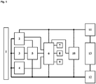
- Fig. 1 shows the block diagram of a preferred embodiment of the device.
- the treatment surface 1 is heated to the treatment temperature with the aid of at least one heating element 2.
- the treatment surface 1 is preferably a contact pad made of ceramic or gold.
- Semiconductor components such as FETs, very preferably MOSFETs, have proven to be particularly advantageous as heating elements 2. In addition to their small dimensions, they are characterized by a very dynamic generation and release of heat and a particularly fast response behavior.
- the regulation of the temperature of the treatment surface 1 takes place with the aid of a regulating device 6, which is preferably a microcontroller and controls the power supply to the heating elements 2.
- the temperature of the treatment surface 1 is monitored with the aid of a first temperature sensor 4, which is preferably an NTC thermal transistor.
- the control device 6 can set the optimal power supply in order to keep the treatment temperature constant for the desired period of time.
- a visual display 7, preferably an LED, and a sound generator 8, preferably a buzzer indicate the phase of the treatment cycle to the user. For example, when the heating phase starts, the sounder 8 can emit a buzz tone and the optical display 7 can be made to light up.
- the preferred treatment time is entered using the input element 9, which is preferably a button.
- the various program sequences and the regulation of the temperature of the treatment surface 1 are controlled by the control device 6.
- the current or voltage supply of the device is provided by a power supply unit 13, for example a battery.
- the hardware-implemented temperature monitor allows the heating elements 2 to be switched off when a maximum temperature is exceeded.
- the device has a second temperature sensor 3, preferably an NTC thermistor, which is connected to a comparator 5. If the temperature of the treatment surface 1 rises, the voltage value at the comparator 5 controlled by the second temperature sensor 3 moves towards a reference value of the voltage which corresponds to a predetermined maximum temperature. As soon as the temperature of the treatment area 1 exceeds the maximum temperature, the output signal at the comparator 5 changes binary, whereby the supply voltage of the heating elements 2 is interrupted.
- the device In addition to the hardware-implemented temperature monitor, the device also has a safety fuse 11, which functions as an additional safety element.
- the heating elements 2 draw a defined treatment current from the power supply unit 13 in a trouble-free operation. If the heating elements 2 overheat due to a defect, the supply current rises sharply.
- the fuse 11 is advantageously triggered from a maximum current. As a result, uncontrolled heating of the treatment surface 1 can be avoided even in the event of a short circuit in the device.
- this safety mechanism only has to intervene if both the temperature regulation by the control device 6 and by the hardware-implemented temperature monitor do not function properly.
- the device also comprises a voltage supply reverse polarity protection 12 and a voltage monitor 10, which is preferably a supply voltage supervisor (SVS).
- SVS supply voltage supervisor
Landscapes
- Health & Medical Sciences (AREA)
- Engineering & Computer Science (AREA)
- Life Sciences & Earth Sciences (AREA)
- Animal Behavior & Ethology (AREA)
- General Health & Medical Sciences (AREA)
- Public Health (AREA)
- Veterinary Medicine (AREA)
- Biomedical Technology (AREA)
- Heart & Thoracic Surgery (AREA)
- Vascular Medicine (AREA)
- Physics & Mathematics (AREA)
- Thermal Sciences (AREA)
- Chemical Kinetics & Catalysis (AREA)
- Chemical & Material Sciences (AREA)
- Bioinformatics & Cheminformatics (AREA)
- General Chemical & Material Sciences (AREA)
- Medicinal Chemistry (AREA)
- Nuclear Medicine, Radiotherapy & Molecular Imaging (AREA)
- Organic Chemistry (AREA)
- Pharmacology & Pharmacy (AREA)
- Dermatology (AREA)
- Thermotherapy And Cooling Therapy Devices (AREA)
- Pharmaceuticals Containing Other Organic And Inorganic Compounds (AREA)
- Materials For Medical Uses (AREA)
- Medicines That Contain Protein Lipid Enzymes And Other Medicines (AREA)
- Catching Or Destruction (AREA)
- Finger-Pressure Massage (AREA)
- Medicinal Preparation (AREA)
- Control And Other Processes For Unpacking Of Materials (AREA)
- Chemical Or Physical Treatment Of Fibers (AREA)
- Surgical Instruments (AREA)
Priority Applications (2)
| Application Number | Priority Date | Filing Date | Title |
|---|---|---|---|
| PL17736689T PL3484423T3 (pl) | 2016-07-12 | 2017-07-12 | Urządzenie do hipertermicznego leczenia swędzenia |
| HRP20220417TT HRP20220417T1 (hr) | 2016-07-12 | 2017-07-12 | Uređaj za hipertermalno liječenje svrbeža |
Applications Claiming Priority (3)
| Application Number | Priority Date | Filing Date | Title |
|---|---|---|---|
| EP16179093.6A EP3269340B1 (de) | 2016-07-12 | 2016-07-12 | Vorrichtung zur hyperthermischen behandlung von pruritus |
| EP16193220.7A EP3308752B1 (de) | 2016-10-11 | 2016-10-11 | Vorrichtung zur hyperthermischen behandlung von juckreiz |
| PCT/EP2017/067544 WO2018011263A1 (de) | 2016-07-12 | 2017-07-12 | Vorrichtung zur hyperthermischen behandlung von juckreiz |
Publications (2)
| Publication Number | Publication Date |
|---|---|
| EP3484423A1 EP3484423A1 (de) | 2019-05-22 |
| EP3484423B1 true EP3484423B1 (de) | 2021-12-29 |
Family
ID=59285261
Family Applications (2)
| Application Number | Title | Priority Date | Filing Date |
|---|---|---|---|
| EP17736689.5A Active EP3484423B1 (de) | 2016-07-12 | 2017-07-12 | Vorrichtung zur hyperthermischen behandlung von juckreiz |
| EP17735608.6A Withdrawn EP3484422A1 (de) | 2016-07-12 | 2017-07-12 | Vorrichtung zur hyperthermischen behandlung von pruritus |
Family Applications After (1)
| Application Number | Title | Priority Date | Filing Date |
|---|---|---|---|
| EP17735608.6A Withdrawn EP3484422A1 (de) | 2016-07-12 | 2017-07-12 | Vorrichtung zur hyperthermischen behandlung von pruritus |
Country Status (17)
| Country | Link |
|---|---|
| US (2) | US20190290476A1 (pl) |
| EP (2) | EP3484423B1 (pl) |
| JP (3) | JP2019521825A (pl) |
| KR (2) | KR102456457B1 (pl) |
| CN (2) | CN109475426A (pl) |
| AU (2) | AU2017295000B2 (pl) |
| BR (1) | BR112019000502B1 (pl) |
| CA (2) | CA3030221A1 (pl) |
| DK (1) | DK3484423T3 (pl) |
| ES (1) | ES2912062T3 (pl) |
| HU (1) | HUE058171T2 (pl) |
| MX (2) | MX2019000405A (pl) |
| PL (1) | PL3484423T3 (pl) |
| SG (2) | SG11201900257UA (pl) |
| TW (2) | TWI772314B (pl) |
| WO (2) | WO2018011263A1 (pl) |
| ZA (1) | ZA201900197B (pl) |
Families Citing this family (13)
| Publication number | Priority date | Publication date | Assignee | Title |
|---|---|---|---|---|
| TWI772314B (zh) * | 2016-07-12 | 2022-08-01 | 德商得瑪法公司 | 用於瘙癢症的高熱治療之裝置 |
| DE102017006994A1 (de) | 2017-07-24 | 2019-01-24 | Stefan Hotz | Koppelbare portable Vorrichtung zur thermisch - medizinischen Behandlung der Haut |
| EP3620141A1 (de) * | 2018-09-05 | 2020-03-11 | Dermapharm AG | Vorrichtung zur behandlung von juckreiz und herpeserkrankungen mit einem kontaktsensor |
| EP3620142A1 (de) * | 2018-09-05 | 2020-03-11 | Dermapharm AG | Vorrichtung zur behandlung von herpeserkrankungen |
| TW202023486A (zh) | 2018-09-05 | 2020-07-01 | 德商得瑪法公司 | 用於治療疱疹疾病之裝置 |
| TWI728589B (zh) * | 2019-12-12 | 2021-05-21 | 國立臺灣大學 | 以熱作用於活體組織的方法及裝置 |
| USD930845S1 (en) | 2019-01-23 | 2021-09-14 | Dermapharm Ag | Apparatus for thermotherapy |
| TWD208233S (zh) | 2019-06-18 | 2020-11-11 | 德商得瑪法公司 | 熱療裝置 |
| DE102019131115A1 (de) * | 2019-11-18 | 2021-05-20 | Ingo Stuckmann | Vorrichtung zur Erzeugung einer lokalen Hyperthermie |
| JP7007536B1 (ja) | 2020-10-17 | 2022-01-24 | 株式会社モストハーモニー | 痒み消し器具 |
| CN114209486B (zh) * | 2021-11-04 | 2024-07-16 | 海杰亚(北京)医疗器械有限公司 | 一种冷热复合式止痒装置 |
| DE102021132177B4 (de) | 2021-12-07 | 2025-01-16 | Beurer Gmbh | Vorrichtung zur Behandlung von Insektenstichen und -bissen mit Beleuchtung |
| CN217366261U (zh) * | 2022-01-24 | 2022-09-06 | 中山市特莱斯电子有限公司 | 一种止痒器 |
Family Cites Families (51)
| Publication number | Priority date | Publication date | Assignee | Title |
|---|---|---|---|---|
| US4961422A (en) * | 1983-01-21 | 1990-10-09 | Marchosky J Alexander | Method and apparatus for volumetric interstitial conductive hyperthermia |
| ES2040880T3 (es) * | 1987-10-07 | 1993-11-01 | Georges Ratkoff | Aparato portatil para el calentamiento local de la piel con fines terapeuticos. |
| US5451747A (en) * | 1992-03-03 | 1995-09-19 | Sunbeam Corporation | Flexible self-regulating heating pad combination and associated method |
| CN2163627Y (zh) * | 1993-04-22 | 1994-05-04 | 郑然� | 可组合便携式射频热疗仪 |
| US7537605B2 (en) * | 1993-10-04 | 2009-05-26 | Huan-Chen Li | Medical device for treating skin itch and rash |
| US6635075B2 (en) * | 1993-10-04 | 2003-10-21 | Huan-Chen Li | Method and apparatus for treatment of skin itch and disease |
| US6245093B1 (en) * | 1993-10-04 | 2001-06-12 | Huan-Chen Li | Method and apparatus for treatment of skin itch and disease |
| CN1103210C (zh) * | 1993-11-24 | 2003-03-19 | 李欢成 | 用热止痒及治皮疹粉刺的仪器 |
| JPH0810280A (ja) * | 1994-06-28 | 1996-01-16 | Toyonari Harada | 局所皮膚温熱器 |
| JPH10229995A (ja) * | 1997-02-20 | 1998-09-02 | Matsushita Electric Ind Co Ltd | 炎症抑制装置 |
| KR200163627Y1 (ko) * | 1997-12-26 | 2000-01-15 | 유무성 | 저항을 이용한 멀티스위치를 사용하는 장치 |
| US7744640B1 (en) * | 1999-08-11 | 2010-06-29 | Medical Products, Inc. | Thermal treatment garment and method of thermally treating body portions |
| DE19954424A1 (de) * | 1999-11-11 | 2001-06-07 | Hansgeorg Schuldzig | Einrichtung zur lokalen thermischen Behandlung von Insektenstichen und -bissen |
| US9877526B2 (en) * | 2001-04-19 | 2018-01-30 | William S. Haas | Controllable thermal warming devices |
| JP3086045U (ja) * | 2001-11-14 | 2002-05-31 | 敏雄 中島 | 電気式温度調整付きかゆみ止めヒータ |
| US6613953B1 (en) * | 2002-03-22 | 2003-09-02 | Dan Altura | Insulator-conductor device for maintaining a wound near normal body temperature |
| US7137979B2 (en) * | 2003-05-31 | 2006-11-21 | Tyrell, Inc. | Methods and devices for the treatment of skin lesions |
| CN2748051Y (zh) * | 2004-09-28 | 2005-12-28 | 贺加赞 | 快速止痒仪 |
| US7494492B2 (en) * | 2004-12-10 | 2009-02-24 | Therative, Inc. | Skin treatment device |
| AU2005313927A1 (en) * | 2004-12-10 | 2006-06-15 | Koninklijke Philips Electronics N.V. | Devices and methods for treatment of skin conditions |
| CA2589984A1 (en) * | 2005-01-03 | 2006-07-13 | Jong-Jin Kil | Temperature controller and temperature control method, and heating wire for blocking electromagnetic waves |
| DE102005002946A1 (de) | 2005-01-18 | 2006-07-27 | Bsm - Bionic Solution Management Gmbh | Herpesbehandlungseinrichtung |
| JP2008540050A (ja) * | 2005-05-18 | 2008-11-20 | タイレル、インク | 熱を印加して皮膚病変を治療するための治療装置および方法 |
| CN2882574Y (zh) * | 2005-07-29 | 2007-03-28 | 陈仁智 | 蚊叮烫电子温灸棒 |
| WO2007082648A1 (de) * | 2006-01-13 | 2007-07-26 | E.I.S. Gmbh | Handgerät und verfahren zum thermischen behandeln der durch einen insektenstich oder -biss betroffenen stelle |
| CN200957128Y (zh) * | 2006-10-23 | 2007-10-10 | 周雷 | 快速、安全、有效的电子止痒仪 |
| CN103083131B (zh) | 2007-01-17 | 2015-07-22 | 眼泪科学公司 | 用于治疗睑板腺功能障碍的热处理的方法、系统和装置 |
| WO2010054859A1 (de) * | 2008-11-17 | 2010-05-20 | Uterstaedt Andrea | Anti-falten-stift |
| EP2206483A1 (de) * | 2009-01-12 | 2010-07-14 | Andrea Uterstädt | Anti-Falten-Stift |
| US8523791B2 (en) * | 2009-08-11 | 2013-09-03 | Laboratoire Naturel Paris, Llc | Multi-modal drug delivery system |
| KR101159779B1 (ko) | 2009-08-17 | 2012-06-26 | (주)메딕콘 | 광 및 열을 병용하는 휴대용 피부 질환 치료기 |
| KR101193527B1 (ko) * | 2009-08-17 | 2012-10-22 | (주)메딕콘 | 광 및 열을 병용하는 휴대용 피부 질환 치료기 및 그 제어 방법 |
| US8143559B2 (en) * | 2009-09-01 | 2012-03-27 | Advance Thermo Control, Ltd. | Heating pad with temperature control and safety protection device |
| US20110172750A1 (en) * | 2010-01-11 | 2011-07-14 | David Ellsworth Cassidy | Methods and apparatus for active patient warming |
| WO2011094412A1 (en) * | 2010-01-27 | 2011-08-04 | Bruder Healthcare Company | Heating element with thermal fuse |
| GB201203927D0 (en) * | 2012-03-06 | 2012-04-18 | Semblant Ltd | Coated electrical assembly |
| US20110208268A1 (en) * | 2010-02-25 | 2011-08-25 | Brown Timothy R | System and method for power-on-reset detection and decoding |
| US20130172966A1 (en) | 2010-03-29 | 2013-07-04 | Eliahu ARAD | System for controlling the temperature of a person |
| US8491508B2 (en) * | 2010-09-15 | 2013-07-23 | Walton F. Smith | Device and method for stimulating the meibomian glands of the eyelid |
| CN201920972U (zh) * | 2011-01-10 | 2011-08-10 | 温昱紘 | 一种电热除痒器 |
| JP2012165906A (ja) * | 2011-02-15 | 2012-09-06 | Medicon Co Ltd | 光及び熱を併用する携帯用皮膚疾患治療機およびその制御方法 |
| CA2839762C (en) * | 2011-06-17 | 2019-09-10 | My Core Control, LLC | Electronic personal thermal control apparatus and system |
| KR101273617B1 (ko) * | 2011-11-24 | 2013-06-10 | 주식회사 루트로닉 | 고주파를 이용한 치료장치 |
| CN102429762A (zh) * | 2011-12-10 | 2012-05-02 | 白吉荣 | 蚊虫叮咬自控电热杀毒止痒器及其使用方法 |
| WO2013168168A1 (en) * | 2012-05-09 | 2013-11-14 | Medoc Ltd. | Improved thermal stimulation probe and method |
| JP2014117395A (ja) * | 2012-12-14 | 2014-06-30 | Shiseido Co Ltd | 痒み抑制装置 |
| US20140352325A1 (en) * | 2013-06-03 | 2014-12-04 | Wendell Brown | Electronic coldpack and method of use |
| FR3010618B1 (fr) * | 2013-09-18 | 2018-01-05 | Oreal | Dispositif a effet peltier pour creer une sensation de froid ou de chaud |
| CN203662967U (zh) * | 2014-01-06 | 2014-06-25 | 深圳市圳远塑胶模具有限公司 | 一种昆虫叮咬治疗器 |
| CN105534634A (zh) * | 2014-10-27 | 2016-05-04 | 深圳市伦琴科技有限公司 | 儿童与成人双模式热疗、光疗及磁疗皮肤物理治疗仪 |
| TWI772314B (zh) * | 2016-07-12 | 2022-08-01 | 德商得瑪法公司 | 用於瘙癢症的高熱治療之裝置 |
-
2017
- 2017-07-11 TW TW106123227A patent/TWI772314B/zh active
- 2017-07-11 TW TW106123228A patent/TWI744353B/zh not_active IP Right Cessation
- 2017-07-12 HU HUE17736689A patent/HUE058171T2/hu unknown
- 2017-07-12 DK DK17736689.5T patent/DK3484423T3/da active
- 2017-07-12 AU AU2017295000A patent/AU2017295000B2/en not_active Ceased
- 2017-07-12 SG SG11201900257UA patent/SG11201900257UA/en unknown
- 2017-07-12 US US16/317,129 patent/US20190290476A1/en not_active Abandoned
- 2017-07-12 CN CN201780043034.0A patent/CN109475426A/zh active Pending
- 2017-07-12 JP JP2019523178A patent/JP2019521825A/ja active Pending
- 2017-07-12 WO PCT/EP2017/067544 patent/WO2018011263A1/de not_active Ceased
- 2017-07-12 KR KR1020197004025A patent/KR102456457B1/ko active Active
- 2017-07-12 CA CA3030221A patent/CA3030221A1/en active Pending
- 2017-07-12 BR BR112019000502-1A patent/BR112019000502B1/pt active IP Right Grant
- 2017-07-12 EP EP17736689.5A patent/EP3484423B1/de active Active
- 2017-07-12 WO PCT/EP2017/067542 patent/WO2018011262A1/de not_active Ceased
- 2017-07-12 ES ES17736689T patent/ES2912062T3/es active Active
- 2017-07-12 CN CN201780043512.8A patent/CN109475427B/zh active Active
- 2017-07-12 AU AU2017295935A patent/AU2017295935B2/en active Active
- 2017-07-12 JP JP2019523179A patent/JP7129407B2/ja active Active
- 2017-07-12 MX MX2019000405A patent/MX2019000405A/es unknown
- 2017-07-12 KR KR1020197004012A patent/KR102485936B1/ko active Active
- 2017-07-12 MX MX2019000408A patent/MX387307B/es unknown
- 2017-07-12 CA CA3030224A patent/CA3030224A1/en active Pending
- 2017-07-12 US US16/317,147 patent/US11759348B2/en active Active
- 2017-07-12 EP EP17735608.6A patent/EP3484422A1/de not_active Withdrawn
- 2017-07-12 SG SG11201900258XA patent/SG11201900258XA/en unknown
- 2017-07-12 PL PL17736689T patent/PL3484423T3/pl unknown
-
2019
- 2019-01-11 ZA ZA2019/00197A patent/ZA201900197B/en unknown
-
2022
- 2022-06-30 JP JP2022105679A patent/JP2022133362A/ja active Pending
Non-Patent Citations (1)
| Title |
|---|
| None * |
Also Published As
Similar Documents
| Publication | Publication Date | Title |
|---|---|---|
| EP3484423B1 (de) | Vorrichtung zur hyperthermischen behandlung von juckreiz | |
| EP3846753B1 (de) | Vorrichtung zur behandlung von juckreiz und herpeserkrankungen mit einem kontaktsensor | |
| EP3308752B1 (de) | Vorrichtung zur hyperthermischen behandlung von juckreiz | |
| EP3269340B1 (de) | Vorrichtung zur hyperthermischen behandlung von pruritus | |
| EP3914204A1 (de) | Mobile vorrichtung zur behandlung von juckreiz mit schnittstelle | |
| DE202016008836U1 (de) | Vorrichtung zur hyperthermischen Behandlung von Juckreiz | |
| DE202018105061U1 (de) | Vorrichtung zur Herpesbehandlung durch Wärmeanwendung | |
| EP3620141A1 (de) | Vorrichtung zur behandlung von juckreiz und herpeserkrankungen mit einem kontaktsensor | |
| EP3620142A1 (de) | Vorrichtung zur behandlung von herpeserkrankungen | |
| HK1250906B (en) | Device for hyperthermal treatment of itching | |
| BR112019000498B1 (pt) | Dispositivo para tratamento hipertérmico de prurido | |
| DE102013017912A1 (de) | Verfahren und Vorrichtung zur Erhöhung der Sicherheit von Medizinprodukten mit Energieeintrag in den Körper | |
| HK1250906A1 (zh) | 用於高温处理瘙痒的装置 | |
| EA040683B1 (ru) | Устройство для гипертермического лечения прурита | |
| DE102011100992A1 (de) | Medizingerät zur sofortigen Linderung des Juckreizes bei atopischen Ekzem |
Legal Events
| Date | Code | Title | Description |
|---|---|---|---|
| REG | Reference to a national code |
Ref country code: HR Ref legal event code: TUEP Ref document number: P20220417 Country of ref document: HR |
|
| STAA | Information on the status of an ep patent application or granted ep patent |
Free format text: STATUS: UNKNOWN |
|
| STAA | Information on the status of an ep patent application or granted ep patent |
Free format text: STATUS: THE INTERNATIONAL PUBLICATION HAS BEEN MADE |
|
| PUAI | Public reference made under article 153(3) epc to a published international application that has entered the european phase |
Free format text: ORIGINAL CODE: 0009012 |
|
| STAA | Information on the status of an ep patent application or granted ep patent |
Free format text: STATUS: REQUEST FOR EXAMINATION WAS MADE |
|
| 17P | Request for examination filed |
Effective date: 20190211 |
|
| AK | Designated contracting states |
Kind code of ref document: A1 Designated state(s): AL AT BE BG CH CY CZ DE DK EE ES FI FR GB GR HR HU IE IS IT LI LT LU LV MC MK MT NL NO PL PT RO RS SE SI SK SM TR |
|
| AX | Request for extension of the european patent |
Extension state: BA ME |
|
| DAV | Request for validation of the european patent (deleted) | ||
| DAX | Request for extension of the european patent (deleted) | ||
| STAA | Information on the status of an ep patent application or granted ep patent |
Free format text: STATUS: EXAMINATION IS IN PROGRESS |
|
| 17Q | First examination report despatched |
Effective date: 20200207 |
|
| GRAP | Despatch of communication of intention to grant a patent |
Free format text: ORIGINAL CODE: EPIDOSNIGR1 |
|
| STAA | Information on the status of an ep patent application or granted ep patent |
Free format text: STATUS: GRANT OF PATENT IS INTENDED |
|
| RIC1 | Information provided on ipc code assigned before grant |
Ipc: A61F 7/00 20060101AFI20210111BHEP Ipc: A61F 7/02 20060101ALI20210111BHEP Ipc: A61P 17/04 20060101ALN20210111BHEP Ipc: A61P 43/00 20060101ALN20210111BHEP |
|
| INTG | Intention to grant announced |
Effective date: 20210201 |
|
| GRAJ | Information related to disapproval of communication of intention to grant by the applicant or resumption of examination proceedings by the epo deleted |
Free format text: ORIGINAL CODE: EPIDOSDIGR1 |
|
| STAA | Information on the status of an ep patent application or granted ep patent |
Free format text: STATUS: EXAMINATION IS IN PROGRESS |
|
| INTC | Intention to grant announced (deleted) | ||
| GRAP | Despatch of communication of intention to grant a patent |
Free format text: ORIGINAL CODE: EPIDOSNIGR1 |
|
| STAA | Information on the status of an ep patent application or granted ep patent |
Free format text: STATUS: GRANT OF PATENT IS INTENDED |
|
| RIC1 | Information provided on ipc code assigned before grant |
Ipc: A61F 7/00 20060101AFI20210623BHEP Ipc: A61F 7/02 20060101ALI20210623BHEP Ipc: A61P 17/04 20060101ALN20210623BHEP Ipc: A61P 43/00 20060101ALN20210623BHEP |
|
| INTG | Intention to grant announced |
Effective date: 20210720 |
|
| GRAS | Grant fee paid |
Free format text: ORIGINAL CODE: EPIDOSNIGR3 |
|
| GRAA | (expected) grant |
Free format text: ORIGINAL CODE: 0009210 |
|
| STAA | Information on the status of an ep patent application or granted ep patent |
Free format text: STATUS: THE PATENT HAS BEEN GRANTED |
|
| AK | Designated contracting states |
Kind code of ref document: B1 Designated state(s): AL AT BE BG CH CY CZ DE DK EE ES FI FR GB GR HR HU IE IS IT LI LT LU LV MC MK MT NL NO PL PT RO RS SE SI SK SM TR |
|
| REG | Reference to a national code |
Ref country code: GB Ref legal event code: FG4D Free format text: NOT ENGLISH |
|
| REG | Reference to a national code |
Ref country code: CH Ref legal event code: EP |
|
| REG | Reference to a national code |
Ref country code: DE Ref legal event code: R096 Ref document number: 502017012355 Country of ref document: DE |
|
| REG | Reference to a national code |
Ref country code: AT Ref legal event code: REF Ref document number: 1458136 Country of ref document: AT Kind code of ref document: T Effective date: 20220115 |
|
| REG | Reference to a national code |
Ref country code: IE Ref legal event code: FG4D Free format text: LANGUAGE OF EP DOCUMENT: GERMAN |
|
| REG | Reference to a national code |
Ref country code: RO Ref legal event code: EPE Ref country code: DK Ref legal event code: T3 Effective date: 20220325 |
|
| REG | Reference to a national code |
Ref country code: FI Ref legal event code: FGE |
|
| REG | Reference to a national code |
Ref country code: PT Ref legal event code: SC4A Ref document number: 3484423 Country of ref document: PT Date of ref document: 20220404 Kind code of ref document: T Free format text: AVAILABILITY OF NATIONAL TRANSLATION Effective date: 20220328 Ref country code: NO Ref legal event code: T2 Effective date: 20211229 |
|
| REG | Reference to a national code |
Ref country code: NL Ref legal event code: FP |
|
| REG | Reference to a national code |
Ref country code: LT Ref legal event code: MG9D |
|
| REG | Reference to a national code |
Ref country code: SE Ref legal event code: TRGR |
|
| PG25 | Lapsed in a contracting state [announced via postgrant information from national office to epo] |
Ref country code: RS Free format text: LAPSE BECAUSE OF FAILURE TO SUBMIT A TRANSLATION OF THE DESCRIPTION OR TO PAY THE FEE WITHIN THE PRESCRIBED TIME-LIMIT Effective date: 20211229 Ref country code: LT Free format text: LAPSE BECAUSE OF FAILURE TO SUBMIT A TRANSLATION OF THE DESCRIPTION OR TO PAY THE FEE WITHIN THE PRESCRIBED TIME-LIMIT Effective date: 20211229 Ref country code: BG Free format text: LAPSE BECAUSE OF FAILURE TO SUBMIT A TRANSLATION OF THE DESCRIPTION OR TO PAY THE FEE WITHIN THE PRESCRIBED TIME-LIMIT Effective date: 20220329 |
|
| REG | Reference to a national code |
Ref country code: EE Ref legal event code: FG4A Ref document number: E022082 Country of ref document: EE Effective date: 20220325 |
|
| REG | Reference to a national code |
Ref country code: ES Ref legal event code: FG2A Ref document number: 2912062 Country of ref document: ES Kind code of ref document: T3 Effective date: 20220524 |
|
| REG | Reference to a national code |
Ref country code: HR Ref legal event code: T1PR Ref document number: P20220417 Country of ref document: HR |
|
| PG25 | Lapsed in a contracting state [announced via postgrant information from national office to epo] |
Ref country code: LV Free format text: LAPSE BECAUSE OF FAILURE TO SUBMIT A TRANSLATION OF THE DESCRIPTION OR TO PAY THE FEE WITHIN THE PRESCRIBED TIME-LIMIT Effective date: 20211229 |
|
| REG | Reference to a national code |
Ref country code: GR Ref legal event code: EP Ref document number: 20220400697 Country of ref document: GR Effective date: 20220509 |
|
| REG | Reference to a national code |
Ref country code: HU Ref legal event code: AG4A Ref document number: E058171 Country of ref document: HU |
|
| PG25 | Lapsed in a contracting state [announced via postgrant information from national office to epo] |
Ref country code: SM Free format text: LAPSE BECAUSE OF FAILURE TO SUBMIT A TRANSLATION OF THE DESCRIPTION OR TO PAY THE FEE WITHIN THE PRESCRIBED TIME-LIMIT Effective date: 20211229 |
|
| REG | Reference to a national code |
Ref country code: HR Ref legal event code: ODRP Ref document number: P20220417 Country of ref document: HR Payment date: 20220705 Year of fee payment: 6 |
|
| PG25 | Lapsed in a contracting state [announced via postgrant information from national office to epo] |
Ref country code: IS Free format text: LAPSE BECAUSE OF FAILURE TO SUBMIT A TRANSLATION OF THE DESCRIPTION OR TO PAY THE FEE WITHIN THE PRESCRIBED TIME-LIMIT Effective date: 20220429 |
|
| REG | Reference to a national code |
Ref country code: DE Ref legal event code: R097 Ref document number: 502017012355 Country of ref document: DE |
|
| PG25 | Lapsed in a contracting state [announced via postgrant information from national office to epo] |
Ref country code: AL Free format text: LAPSE BECAUSE OF FAILURE TO SUBMIT A TRANSLATION OF THE DESCRIPTION OR TO PAY THE FEE WITHIN THE PRESCRIBED TIME-LIMIT Effective date: 20211229 |
|
| PGFP | Annual fee paid to national office [announced via postgrant information from national office to epo] |
Ref country code: SK Payment date: 20220706 Year of fee payment: 6 Ref country code: RO Payment date: 20220705 Year of fee payment: 6 Ref country code: NO Payment date: 20220720 Year of fee payment: 6 Ref country code: IE Payment date: 20220720 Year of fee payment: 6 Ref country code: HR Payment date: 20220705 Year of fee payment: 6 Ref country code: FI Payment date: 20220719 Year of fee payment: 6 Ref country code: EE Payment date: 20220719 Year of fee payment: 6 Ref country code: CZ Payment date: 20220704 Year of fee payment: 6 |
|
| PLBE | No opposition filed within time limit |
Free format text: ORIGINAL CODE: 0009261 |
|
| STAA | Information on the status of an ep patent application or granted ep patent |
Free format text: STATUS: NO OPPOSITION FILED WITHIN TIME LIMIT |
|
| PGFP | Annual fee paid to national office [announced via postgrant information from national office to epo] |
Ref country code: HU Payment date: 20220802 Year of fee payment: 6 Ref country code: GR Payment date: 20220719 Year of fee payment: 6 |
|
| 26N | No opposition filed |
Effective date: 20220930 |
|
| PG25 | Lapsed in a contracting state [announced via postgrant information from national office to epo] |
Ref country code: SI Free format text: LAPSE BECAUSE OF FAILURE TO SUBMIT A TRANSLATION OF THE DESCRIPTION OR TO PAY THE FEE WITHIN THE PRESCRIBED TIME-LIMIT Effective date: 20211229 Ref country code: MC Free format text: LAPSE BECAUSE OF FAILURE TO SUBMIT A TRANSLATION OF THE DESCRIPTION OR TO PAY THE FEE WITHIN THE PRESCRIBED TIME-LIMIT Effective date: 20211229 |
|
| PG25 | Lapsed in a contracting state [announced via postgrant information from national office to epo] |
Ref country code: LU Free format text: LAPSE BECAUSE OF NON-PAYMENT OF DUE FEES Effective date: 20220712 |
|
| P01 | Opt-out of the competence of the unified patent court (upc) registered |
Effective date: 20230509 |
|
| PGFP | Annual fee paid to national office [announced via postgrant information from national office to epo] |
Ref country code: SE Payment date: 20230724 Year of fee payment: 7 Ref country code: DK Payment date: 20230724 Year of fee payment: 7 |
|
| REG | Reference to a national code |
Ref country code: HR Ref legal event code: PBON Ref document number: P20220417 Country of ref document: HR Effective date: 20230712 |
|
| REG | Reference to a national code |
Ref country code: EE Ref legal event code: MM4A Ref document number: E022082 Country of ref document: EE Effective date: 20230731 |
|
| REG | Reference to a national code |
Ref country code: NO Ref legal event code: MMEP |
|
| REG | Reference to a national code |
Ref country code: SK Ref legal event code: MM4A Ref document number: E 39608 Country of ref document: SK Effective date: 20230712 |
|
| PG25 | Lapsed in a contracting state [announced via postgrant information from national office to epo] |
Ref country code: GR Free format text: LAPSE BECAUSE OF NON-PAYMENT OF DUE FEES Effective date: 20240207 |
|
| REG | Reference to a national code |
Ref country code: IE Ref legal event code: MM4A |
|
| PG25 | Lapsed in a contracting state [announced via postgrant information from national office to epo] |
Ref country code: RO Free format text: LAPSE BECAUSE OF NON-PAYMENT OF DUE FEES Effective date: 20230712 Ref country code: MK Free format text: LAPSE BECAUSE OF FAILURE TO SUBMIT A TRANSLATION OF THE DESCRIPTION OR TO PAY THE FEE WITHIN THE PRESCRIBED TIME-LIMIT Effective date: 20211229 Ref country code: HU Free format text: LAPSE BECAUSE OF NON-PAYMENT OF DUE FEES Effective date: 20230713 Ref country code: GR Free format text: LAPSE BECAUSE OF NON-PAYMENT OF DUE FEES Effective date: 20240207 Ref country code: FI Free format text: LAPSE BECAUSE OF NON-PAYMENT OF DUE FEES Effective date: 20230712 Ref country code: EE Free format text: LAPSE BECAUSE OF NON-PAYMENT OF DUE FEES Effective date: 20230731 Ref country code: CZ Free format text: LAPSE BECAUSE OF NON-PAYMENT OF DUE FEES Effective date: 20230712 Ref country code: CY Free format text: LAPSE BECAUSE OF FAILURE TO SUBMIT A TRANSLATION OF THE DESCRIPTION OR TO PAY THE FEE WITHIN THE PRESCRIBED TIME-LIMIT Effective date: 20211229 Ref country code: SK Free format text: LAPSE BECAUSE OF NON-PAYMENT OF DUE FEES Effective date: 20230712 |
|
| PG25 | Lapsed in a contracting state [announced via postgrant information from national office to epo] |
Ref country code: NO Free format text: LAPSE BECAUSE OF NON-PAYMENT OF DUE FEES Effective date: 20230731 Ref country code: HR Free format text: LAPSE BECAUSE OF NON-PAYMENT OF DUE FEES Effective date: 20230712 |
|
| PG25 | Lapsed in a contracting state [announced via postgrant information from national office to epo] |
Ref country code: IE Free format text: LAPSE BECAUSE OF NON-PAYMENT OF DUE FEES Effective date: 20230712 |
|
| PG25 | Lapsed in a contracting state [announced via postgrant information from national office to epo] |
Ref country code: IE Free format text: LAPSE BECAUSE OF NON-PAYMENT OF DUE FEES Effective date: 20230712 |
|
| PG25 | Lapsed in a contracting state [announced via postgrant information from national office to epo] |
Ref country code: MT Free format text: LAPSE BECAUSE OF FAILURE TO SUBMIT A TRANSLATION OF THE DESCRIPTION OR TO PAY THE FEE WITHIN THE PRESCRIBED TIME-LIMIT Effective date: 20211229 |
|
| REG | Reference to a national code |
Ref country code: DK Ref legal event code: EBP Effective date: 20240731 |
|
| REG | Reference to a national code |
Ref country code: SE Ref legal event code: EUG |
|
| PG25 | Lapsed in a contracting state [announced via postgrant information from national office to epo] |
Ref country code: DK Free format text: LAPSE BECAUSE OF NON-PAYMENT OF DUE FEES Effective date: 20240731 |
|
| PGFP | Annual fee paid to national office [announced via postgrant information from national office to epo] |
Ref country code: NL Payment date: 20250723 Year of fee payment: 9 |
|
| PGFP | Annual fee paid to national office [announced via postgrant information from national office to epo] |
Ref country code: ES Payment date: 20250819 Year of fee payment: 9 Ref country code: PT Payment date: 20250702 Year of fee payment: 9 |
|
| PGFP | Annual fee paid to national office [announced via postgrant information from national office to epo] |
Ref country code: DE Payment date: 20250627 Year of fee payment: 9 |
|
| PG25 | Lapsed in a contracting state [announced via postgrant information from national office to epo] |
Ref country code: SE Free format text: LAPSE BECAUSE OF NON-PAYMENT OF DUE FEES Effective date: 20240713 |
|
| PGFP | Annual fee paid to national office [announced via postgrant information from national office to epo] |
Ref country code: PL Payment date: 20250708 Year of fee payment: 9 Ref country code: TR Payment date: 20250708 Year of fee payment: 9 Ref country code: IT Payment date: 20250731 Year of fee payment: 9 |
|
| PGFP | Annual fee paid to national office [announced via postgrant information from national office to epo] |
Ref country code: GB Payment date: 20250724 Year of fee payment: 9 Ref country code: BE Payment date: 20250722 Year of fee payment: 9 |
|
| PGFP | Annual fee paid to national office [announced via postgrant information from national office to epo] |
Ref country code: FR Payment date: 20250723 Year of fee payment: 9 Ref country code: AT Payment date: 20250721 Year of fee payment: 9 |
|
| PGFP | Annual fee paid to national office [announced via postgrant information from national office to epo] |
Ref country code: CH Payment date: 20250801 Year of fee payment: 9 |