EP3483667B1 - Befestigungssystem eines uhrwerks in einem armbanduhrengehäuse - Google Patents
Befestigungssystem eines uhrwerks in einem armbanduhrengehäuse Download PDFInfo
- Publication number
- EP3483667B1 EP3483667B1 EP17201348.4A EP17201348A EP3483667B1 EP 3483667 B1 EP3483667 B1 EP 3483667B1 EP 17201348 A EP17201348 A EP 17201348A EP 3483667 B1 EP3483667 B1 EP 3483667B1
- Authority
- EP
- European Patent Office
- Prior art keywords
- movement
- clamp
- flange
- timepiece
- watch case
- Prior art date
- Legal status (The legal status is an assumption and is not a legal conclusion. Google has not performed a legal analysis and makes no representation as to the accuracy of the status listed.)
- Active
Links
Images


Classifications
-
- G—PHYSICS
- G04—HOROLOGY
- G04B—MECHANICALLY-DRIVEN CLOCKS OR WATCHES; MECHANICAL PARTS OF CLOCKS OR WATCHES IN GENERAL; TIME PIECES USING THE POSITION OF THE SUN, MOON OR STARS
- G04B37/00—Cases
- G04B37/04—Mounting the clockwork in the case; Shock absorbing mountings
- G04B37/05—Fixed mountings for pocket or wrist watches
- G04B37/052—Fixed mountings for pocket or wrist watches with shock damping means not related to the winding stem
Definitions
- the invention relates to a timepiece comprising a system for attaching a watch movement to a watch case element.
- Two or three casing flanges are generally used for assembling or fixing a watch movement within a watch case, particularly within a caseband.
- each casing flange When assembling the movement within the case, each casing flange is inserted into a cutout formed on the internal circumference of the caseband, then secured to the movement by means of a fastening means.
- This cutout may in particular be shaped so that the flange can induce an adequate prestressing force, which makes it possible to press the movement against the case middle in order to satisfy predefined criteria.
- a criterion may, for example, be a minimization of the amplitude of movement travel for a given shock intensity, as well as a given flange geometry and material, without risk of plasticization of the flanges.
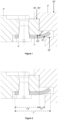
- FIGS. 1 and 2 illustrate a construction of such a flanged fitting device.
- At least one flange 1* is pressed against flat and parallel surfaces 2a*, 3a*, which are respectively associated with a movement 2* and a caseband 3* of a caseband 30*.
- the flange 1* is thus elastically deformed during assembly of the movement so that the elastic restoring force of the flange maintains a surface 2b* of the movement 2* against a surface 3b* of the caseband 3*.
- the holding of the flange on the movement is here ensured by a screw 4*.
- the document DE2316784A1 describes a casing system comprising a casing element returned to the bottom of a caseband using a flange 11 bearing, at one of its ends, against a side of a groove made in the caseband and being fixed to the casing element by screws at the other of its ends.
- the document EP1182522A1 describes a system for attaching a back to a caseband.
- This system comprises a ring made of shape memory material.
- the ring is designed to press against a surface of the back and against a groove made in the caseband in a room temperature configuration.
- the aim of the invention is to provide a system for fixing a watch movement in a watch case making it possible to overcome the drawbacks mentioned above and to improve the devices known from the prior art.
- the invention proposes a fixing system whose reliability and robustness is improved relative to the systems known from the prior art.
- a timepiece is defined by claim 1.
- the timepiece is for example a watch, in particular a wristwatch.
- the timepiece comprises a watch case or a watch case 30 comprising a caseband 3.
- the watch case 30 contains a watch movement 2.
- the movement may be a mechanical movement or an electronic movement.
- the watch movement 2 and/or an element 3 of the watch case and/or the watch case 30 may constitute or be part of a watch assembly 200 comprising or taking part in a system 10 for attaching the watch movement 2 to the element 3 of the watch case 30.
- the watch case element may for example be a case middle or an enlarging circle.
- the system has the particularity of implementing elastic casing flanges whose rigidities are likely to vary depending on the stresses applied to them, in particular when moving the watch movement in relation to the watch case in the event of an impact or when assembling the movement to the case.
- the system has the particularity of implementing a particularly rigid casing that is not very sensitive to variations in manufacturing and/or assembly tolerances.
- Such an embodiment has the advantage of proposing a durable fastening system, which in particular avoids the risks of plastic deformation of the flanges taking part in the assembly and/or the risks of untimely disassembly of the fastening means of said flanges, in particular in the event of an impact to the watch.
- the stiffness of a flange can be characterized by the intensity of its deflection following a given stress or force. It is possible to modulate the stiffness of a flange by modifying its active length and/or by modifying its support points or surfaces during its loading. The stiffness modification device exploits this possibility.
- the device for modifying the rigidity of the at least one flange is preferably arranged such that the bent length of the at least one flange is modified, in particular such that the bent length of the at least one flange is reduced, when the movement is fixed to the watch case element or moved relative to the watch case element from a rest position in which a first surface 2b of the movement is in contact with a second surface 3b of the case element.
- the first surface 2b is for example a face of the movement.
- the second surface 3b is for example a bearing surface made in the case, for example in the caseband.
- At least one flange 1 is pressed against a surface 2A of the movement.
- the at least one flange bears against a surface 3A of the case, in particular against an end of a surface 3A of the case.
- the surface 3A is for example a bearing surface of a cutout 31 or a recess 31 made in the case element, in particular in the caseband.
- the flange 1 is thus elastically deformed during assembly of the movement so that the elastic restoring force of the flange holds the surface 2b of the movement 2 against the surface 3b of the case 3.
- the holding of the flange on the movement is here ensured by a screw 4.
- the screw 4 is for example screwed into a tapping provided in the movement.
- the screw passes through a hole 14 made in the flange 1.
- the head of the screw bears against a surface of the flange 1.
- the first and second surfaces 2b and 3b are, for example, flat. They are preferably perpendicular to an axis A1 of the movement.
- This axis A1 is perpendicular to a plane of the movement, in particular to a plane of a frame of the movement and/or the axis A1 is parallel to the direction in which the movement is introduced into the watch case element 3.
- the active bending length Lf of the flange corresponds to a limited portion of the total length L of the flange.
- the active bending length Lf extends between a first zone forming a first bent end 12 and a second zone forming a second bent end 13.
- the first end 12 is at the contact limit between the movement and the flange.
- the second end 13 is at the contact limit between the box and the flange.
- the length La is the length of the flange which is supported on the movement. This length may possibly be discontinuous. It extends between the extreme limits where the flange 1 is supported on the movement.
- the support surface 2A of the movement comprises at least one surface portion 2a' forming an angle ⁇ with the frame of the movement.
- This portion 2a' is adjacent to a portion 2a against which the screw 4 presses the flange against the frame of the movement.
- the portion 2a is for example flat.
- the surface portion 2a' forms the non-zero angle ⁇ with the portion 2a against which the flange is supported when the movement is in a rest position in which the first surface 2b of the movement is in contact against the second surface 3b of the case element.
- the flange 1 When assembling the movement 2 within the box 30, the flange 1 is elastically deformed by contact with all or part of the surface 3A under the action of the screw 4. The flange is elastically deformed over an axial interference distance corresponding to the material interference between the flange and the box before elastic deformation of the flange. Once the movement is fitted, the flange is pressed against the surface 2A and maintained in a pre-tensioned state by means of the screw 4.
- the bending length Lf of the flange is in particular defined by the geometry of the surface 2A.
- the geometry of the portion 2a' thus gives the flange at least a second rigidity that it is capable of retaining until the elastic restoring force of said flange is restored, i.e. as long as the flange is in contact with the portion 2a'. Furthermore, the portion 2a' makes it possible to distribute the stresses over a larger surface area of the flange and thus avoids excessively high stress concentrations, likely to exceed the elastic limit of the material from which the flange is made.
- the bending length Lf of the flange is likely to vary, it can in particular be between La/4 ( figure 4 ) and La/1.5 ( figure 3 ).
- the length Lf is here likely to vary abruptly from La/1.5 to La/4 between the configuration of the figure 3 and the configuration of the figure 4
- the stress mode of the flange is also likely to be abruptly modified by passing from a configuration similar to that of a fixed beam to a configuration similar to that of a beam in four-point bending.
- the angle ⁇ is preferably strictly less than 45°, or even less than 20°, or even less than 15°, or even less than 10°. This angle ⁇ is preferably greater than 1°, in particular greater than 2°.
- the portion 2a' must be distinguished from a simple chamfer resulting from the manufacture of surface 2A. Portion 2a' may, moreover, occupy all or part of surface 2A.
- the bearing or contact of the first bent end 12 of the flange against the movement is modified when the movement is fixed to the watch case element or moved relative to the watch case element from a rest position in which the first surface 2b of the movement is in contact against the second surface 3b of the case element.
- the device for modifying the rigidity of the at least one flange comprises the portion 2a'.
- the portion 2a' is for example flat.
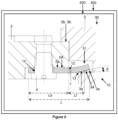
- a second embodiment of a timepiece 400 is described below with reference to figures 5 And 6 .
- the timepiece may differ from that of the first embodiment only by the device for modifying the rigidity of the at least one flange.
- the bearing surface 3A of the box comprises at least one surface portion 3a' forming an angle ⁇ with the frame of the movement or with a plane perpendicular to the axis A1 of the movement.
- This portion 3a' is adjacent to a portion 3a against which the flange rests in the rest position of the movement or during the fixing of the movement in the case.
- the portion 3a is for example flat and is for example perpendicular to the axis A1 of the movement.
- the portion 3a' of surface 3A forms an angle ⁇ with the portion 3a of surface 3A.
- the flange 1 When assembling the movement 2 within the box 30, the flange 1 is elastically deformed by contact with all or part of the surface 3A under the action of the screw 4. The flange is elastically deformed over an axial interference distance corresponding to the material interference between the flange and the box before elastic deformation of the flange. Once the movement is fitted, the flange is pressed against the surface 2A and maintained in a pre-tensioned state by means of the screw 4.
- the bending length Lf of the flange is defined in particular by the geometry of the surface 3A.
- Lf - La/2.5 which gives the flange an initial rigidity that it retains until the flange comes into contact with portion 3a', particularly during an impact whose intensity is greater than a given threshold value.
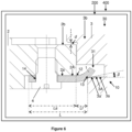
- this threshold value is reached, as shown in the figure 6 .
- the movement is axially displaced by a distance d relative to the box. Consequently, the flange comes into contact with the portion 3a'.
- This contact modifies the support points of the flange, which in particular makes it possible to increase the restoring force of the flange while avoiding its plastic deformation, in particular by a minimized axial displacement of the movement due to the increase in the restoring force.
- the geometry of the portion 3a' thus gives the flange at least a second rigidity that it is capable of retaining until the restoring force is restored. elastic of said flange, either as long as the flange is in contact with portion 3a'.
- the bending length Lf of the flange is likely to vary, it can in particular be between La/4 ( figure 6 ) and La/2.5 ( figure 5 ).
- the length Lf is here likely to vary from La/2.5 to La/4 between the configuration of the figure 5 and the configuration of the figure 6 .
- the angle ⁇ is preferably strictly less than 45°, or even less than 20°, or even less than 15°, or even less than 10°. This angle ⁇ is preferably greater than 1°, in particular greater than 2°.
- the portion 3a' must be distinguished from a simple chamfer resulting from the manufacture of the surface 3A.
- the portion 3a' may, moreover, occupy all or part of the surface 3A.
- the support or contact of the second bent end 13 of the flange against the case element is modified when the movement is fixed to the watch case element or moved relative to the watch case element from a rest position in which the first surface 2b of the movement is in contact against the second surface 3b of the case element.
- the device for modifying the rigidity of the at least one flange comprises the portion 3a'.
- the portion 3a' is for example flat.
- a third embodiment of a timepiece 400 is described below.
- This embodiment is shown in the figure 14 . It combines the first embodiment and the second embodiment.
- the device for modifying the rigidity of the at least one flange comprises a portion inclined on the movement intended to cooperate with the at least one flange (in particular like the portion 2a' of the first embodiment shown in the figures 3 And 4 ) and an inclined portion on the box element intended to cooperate with the at least one flange (in particular like the portion 3a' of the second embodiment shown in the figures 5 And 6 ).
- the bearing or contact of the first bent end 12 of the flange against the movement and the bearing or contact of the second bent end 13 of the flange against the case element are modified when the movement is fixed to the watch case element or moved relative to the watch case element from a rest position in which the first surface 2b of the movement is in contact against the second surface 3b of the case element.
- a flange stiffness modification device is advantageously provided at each flange.
- the flange stiffness modification devices are identical for each flange.
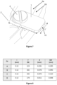
- Each flange may be parallelepipedal or substantially parallelepipedal in shape as shown in the figure 7 .
- a flange or each flange comprises a cross section S whose quadratic moment evolves along a longitudinal axis 11 of the flange.
- the width L' of the flange changes along the longitudinal axis 11. This change is present between the fixing element 14 and the end 15 of the flange, in particular over more than half of the portion extending between the fixing element 14 and the end 15 of the flange.
- the width L' preferably decreases as one approaches the end 15.
- the thickness e of the flange changes along the longitudinal axis 11. This change is present between the fixing element 14 and the end 15 of the flange, in particular over more than half of the portion extending between the fixing element 14 and the end 15 of the flange.
- the thickness e preferably decreases as one approaches the end 15.
- the change in the width and/or thickness and/or geometry of the flange may be such that the cross sections change so that the profile of the maximum stresses in the sections is constant or substantially constant at least over part of the length of the flange, in particular between the fixing element 14 and the end 15 of the flange, in particular over more than half of the portion extending between the fixing element 14 and the end 15 of the flange.
- the flange may, in particular, have a profile of equal resistance to bending or "iso-stress". More generally, the sections of the flange may change so as to distribute the stresses within it as well as possible, and thus to minimize them.
- the portions 2a' have been described as being made on the movement and the portions 3a' have been described as being made on the case element.
- the movement is intended to be assembled directly within a caseband.
- the movement may be assembled on another case element, such as in particular a back or a bezel, intended to be attached to a caseband.
- the watch assembly 200 may also comprise a casing ring or enlargement ring, this casing ring or enlargement ring being able to be secured to the movement or to the caseband by related fixing means.
- the portions 2a' may be made at least in part on the casing ring or the portions 3a' may be made at least in part on the casing ring.
- the casing flanges have been described as fixed to the movement.
- the means for fixing the flanges may be mounted on a casing ring.
- the means for fixing the flanges may be mounted on a case element, in particular on a caseband.
- the portions 2a' and 3a' have been described as planar portions.
- portion 2a' and/or portion 3a' may be convex or domed, in particular in the form of a portion of a cylinder, as shown in the figure 12 for portion 2a'.
- portion 2a' and/or portion 3a' may be discontinuous, in particular formed by a staircase, as shown in the figure 13 for portion 2a'.
- the clearance e1 ( Figure 3 ) between the flange and a point of the movement against which the flange can come into contact by bending of the flange.
- the value of the clearance e1 is less than Lc1, or even less than Lc1/3, or even less than Lc1/4 and/or the value of the clearance e1 is greater than Lc1/60, or even greater than Lc1/30, with Lc1 the length of the projection in the plane of the frame of the movement of the portion 2a'.
- the length Lc1 is between Lf/10 and Lf with Lf measured in the rest state.
- the clearance e2 ( Figure 14 ) between the flange and a point on the box element against which the flange can come into contact by bending of the flange.
- the value of the clearance e2 is less than Lc2, or even less than Lc2/3, or even less than Lc2/4 and/or the value of the clearance e2 is greater than Lc2/60, or even greater than Lc2/30, with Lc2 the length of the projection in the plane of the box element of the portion 3a'.
- the length Lc2 is between Lf/10 and Lf with Lf measured in the rest state.
- each flange has a fixing element 14 for the movement or the box element.
- This element is for example a hole 14 for the passage of a screw 4.
- the flange can be made of steel or a superelastic alloy and/or a shape memory alloy, in particular a nickel-titanium alloy such as Nitinol or a nickel alloy.
- flange 1 may or may not be flat.
- the flange may have an angled geometry.
- Flange 1 may or may not have a symmetrical profile.
- Configuration A corresponds to a nesting configuration according to the prior art illustrated by the Figures 1 and 2 .
- Configuration B corresponds to the nesting configuration of the first embodiment illustrated by the figures 3 And 4 .
- Configuration C corresponds to the nesting configuration of the second embodiment illustrated by the figures 5 And 6 .
- Configuration D corresponds to the nesting configuration of the third embodiment illustrated by the figure 14 .
- configurations B, C, D make it possible to propose a particularly rigid assembly, while minimizing the residual deformations of the flanges, whereas the flanges of configuration A are greatly plasticized due, in particular, to an excessively large axial displacement d produced during the impact.
- Def > I the plasticization of the flange here induces the displacement of the movement of the caseband, namely the loss of contact between the movement and the caseband. After impact, the movement is therefore no longer assembled satisfactorily in the case.
- configuration D makes it possible, for its part, to limit as much as possible the displacement of the movement with respect to the case and to limit as much as possible the residual deformation of the flanges.
- the flanges may have a first and a second rigidity when assembling the movement within the box element or have a second rigidity once the movement is assembled, following a shock of a predefined intensity for example.
- the flange can be made of steel, in particular durnico steel.
- a shape memory alloy such as Nitinol, can advantageously be chosen for its superelastic properties.
- a flange formed from such an alloy has, in fact, the advantage of generating a force varying significantly less than a flange made from durnico steel beyond a given prestress threshold, and this due to the change in phase of the material according to its deformation rate according to the stresses it undergoes during casing or that it is likely to undergo during an impact. This property is therefore particularly advantageous for best compensating for the variations in force induced by the variations in assembly configurations caused by the manufacturing and/or assembly tolerances of the movement and the case, and therefore makes it possible to propose a particularly robust assembly device.
- a flange formed from such a superelastic alloy makes it possible to generate very substantial elastic restoring forces compared with those known from flanged fitting devices known from the prior art.
- the choice of such a material is therefore particularly advantageous. for the purpose of increasing the rigidity of the casing, the advantages of which are those highlighted by means of studies by the applicant, and which are set out in the patent application EP2458456 , namely a spectacular reduction in the acceleration undergone by the movement, for example during an impact on a hard surface.
- the fixing system has an operation comprising a step of modifying the rigidity of the at least one flange, in particular of modifying the bending rigidity of the at least one flange, when the movement is fixed and/or when the movement is moved relative to the watch case element.
- the bent length of the at least one flange is modified, in particular the bent length of the at least one flange is reduced, when the movement is fixed and/or when the movement is moved relative to the watch case element from a rest position in which the first surface 2b of the movement is in contact against the second surface 3b of the watch case element.
- the timepiece 400 in particular a wristwatch, or the assembly 200 comprises a system 10 for attaching a watch movement 2 to an element 3 of a watch case 30, the system comprising at least one flange 1, in particular at least two flanges, preferably three flanges or four flanges, intended to come into contact with the movement on the one hand and with the watch case element on the other hand, the at least one flange being made of an alloy superelastic and/or in a shape memory alloy, in particular in a nickel-titanium alloy such as Nitinol.
- Nitinol is a superelastic and shape memory alloy. Indeed, in a temperature range corresponding to the use of the flanges (-10°C to 40°C for example), Nitinol is in the austenitic phase, therefore superelastic.
- Nitinol is an alloy of Nickel and Titanium in which these two elements are present in approximately the same percentages, i.e. approximately 55% by weight or 60% by weight of Nickel and approximately 45% by weight or 40% by weight of Titanium and possibly additional elements in lesser proportions such as Chromium, Cobalt, or Niobium.
- Other shape memory alloys exist such as AuCd, CuAIBe, CuAINi or CuZnAl in monocrystalline or polycrystalline form.
- Alloys can also undergo specific heat treatments to acquire their superelastic character.
- the 60NiTi alloy is nominally 60 wt% nickel and 40 wt% titanium.
- the 55NiTi alloy is nominally 55 wt% nickel and 45 wt% titanium.
- the Nitinol#1 alloy is 54.5 wt% to 57.0 wt% nickel and between 43.0 wt% and 45.5 wt% titanium with up to 0.25 wt% of other elements such as chromium, cobalt, copper, iron or niobium in particular.
- Nitinol alloy which has been the subject of studies whose results are represented on the Figures 15 to 17 is notably composed of approximately 56% by weight of nickel and approximately 44% by weight of titanium and additional elements such as Cr, Cu, and Fe.
- the alloy CuAI12Be(0.45-0.68) consists nominally of 12 wt% Aluminum and 0.45 wt% to 0.68 wt% Beryllium, with a balance of Copper.
- the alloy CuAI13Ni4 is nominally 83 wt% Copper, 13 wt% Aluminum and 4 wt% Nickel.
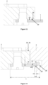
- the figure 15 illustrates a graph showing the evolution of the restoring force generated by two flanges in their elastic domain, respectively made of durnico steel (curve 6) and Nitinol (curve 5a, 5b), as a function of their pre-tension state "interference I", once the movement is fitted according to a configuration A.
- This graph shows a curve 5a, 5b comprising two distinct portions 5a, 5b with substantially different slopes, unlike curve 6 which only has one limited portion.
- the Nitinol flange is prestressed in such a way that it behaves according to the characteristic of portion 5b of the curve.
- the force variation produced by a Nitinol flange is minimized compared to that which a durnico steel flange is likely to produce.
- Nitinol In order to stiffen the casing as best as possible and to contain the superelastic character of the alloy during the casing phase, the geometry of a flange in Nitinol may evolve in relation to the flanges known from the prior art.
- the thickness e of a Nitinol flange may, for example, be increased in relation to that of a flange made of durnico steel, and/or the bending length Lf, constant or not depending on the stresses, may be minimized.
- e ⁇ 0.5 mm for a Nitinol flange Preferably, e ⁇ 0.5 mm for a Nitinol flange.
- Lf ⁇ 1.35 mm for a Nitinol flange Preferably, Lf ⁇ 1.35 mm for a Nitinol flange.
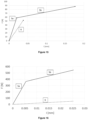
- the figure 16 illustrates a graph showing the evolution of the restoring force generated respectively by two flanges in their elastic domain, respectively made of durnico steel (curve 6) and Nitinol (curve 5a, 5b), as a function of their pre-tension state "interference I", once the movement is fitted according to a configuration A.
- the length Lf of the flange can be reduced at the same time.
- the figure 17 illustrates a graph showing the evolution of the restoring force generated respectively by two flanges in their elastic domain, respectively made of durnico steel (curve 6) and Nitinol (curve 5a, 5b), as a function of their pre-tension state "interference I", once the movement is fitted according to a configuration A.
- Their "iso-stress" geometry " is here comparable to that of the figure 10 with a width L' of the largest dimension of 2.05 mm.
- the active bending length Lf* of the flange corresponds to a limited portion of the total length L* of the flange.
- the length Lf* is notably significantly less than the support length La* of the flange against the movement, in particular Lf* - La*/4.
- This length Lf* may prove insufficient when assembling the movement in the box, which risks inducing a residual deformation of the flange which may reduce the elastic restoring force potentially produced by said flange.
- This situation may notably lead to the loss of contact between the surfaces 2b* and 3b*, which are respectively associated with the movement 2* and the box 3*.
- This situation may also reduce the forces under the head of the screw 4*, which may lead to a risk of inadvertent unscrewing of said screw 4*.
- this length Lf* may then prove excessive once the movement is assembled in the case, in particular in view of a predefined threshold of shock resistance and/or a given amplitude of movement displacement, which also risks inducing a residual deformation of the flange which may reduce the elastic restoring force initially produced by said flange.
- “superelastic alloy” is preferably meant an alloy whose deformation at the elastic limit is greater than 2%, or even greater than 5%, or even greater than 8%.
Landscapes
- Physics & Mathematics (AREA)
- General Physics & Mathematics (AREA)
- Electric Clocks (AREA)
- Clamps And Clips (AREA)
- Casings For Electric Apparatus (AREA)
Claims (13)
- Uhr (400), insbesondere Armbanduhr, umfassend:- ein Uhrwerk (2),- ein Element (3) des Gehäuses (30) der Uhr, und- ein System (10) zur Befestigung des Uhrwerks (2) an dem Element (3) des Gehäuses (30) der Uhr,wobei das Befestigungssystem umfasst:- mindestens einen Bügel (1), insbesondere mindestens zwei Bügel, vorzugsweise drei Bügel oder vier Bügel, der (die) dazu bestimmt ist (sind), mit dem Uhrwerk einerseits und mit dem Uhrgehäuseelement andererseits in Kontakt zu kommen,wobei das Uhrwerk (2) und das Element (3) des Gehäuses (30) derart ausgebildet sind, dass die Anlage oder der Kontakt eines ersten gekrümmten Endes (12) des mindestens einen Bügels an bzw. mit dem Uhrwerk und/oder die Anlage oder der Kontakt eines zweiten gekrümmten Endes (13) des mindestens einen Bügels an bzw. mit dem Gehäuseelement derart erfolgt (erfolgen), dass der Bügel in dem Zustand, in dem das Uhrwerk am Uhrgehäuseelement befestigt ist, oder in dem Zustand, in dem es relativ zum Uhrgehäuseelement aus einer Ruheposition, in der sich eine erste Fläche (2b) des Uhrwerks in Kontakt mit einer zweiten Fläche (3b) des Gehäuseelements befindet, verschoben ist, elastisch verformt wird,wobei die Uhr (400) dadurch gekennzeichnet ist, dass sie in dem Zustand, in dem das Uhrwerk am Gehäuseelement befestigt ist und das Uhrwerk sich in der Ruheposition befindet, ein erstes Spiel (e1) zwischen dem Bügel und einem Punkt des Uhrwerks, mit dem der Bügel durch Biegung des Bügels im verschobenen Zustand in Kontakt kommen kann, umfasst, wobei der Wert des ersten Spiels kleiner als Lc1 oder sogar kleiner als Lc1/3 oder sogar kleiner als Lc1/4 ist und/oder wobei der Wert des ersten Spiels größer als Lc1/60 oder sogar größer als Lc1/30 ist, wobei Lc1 die Länge einer Projektion einer dritten Fläche (2a') des Uhrwerks, an welcher der Bügel im verschobenen Zustand zur Anlage kommen kann, auf die Ebene des Uhrwerks ist, wobei die Länge Lc1 zwischen Lf/10 und Lf liegt, wobei Lf die Länge des durchgebogenen Bügels ist,und/oder dadurch, dass die Uhr (400) in dem Zustand, in dem das Uhrwerk am Gehäuseelement befestigt ist und das Uhrwerk sich in der Ruheposition befindet, ein zweites Spiel (e2) zwischen dem Bügel und einem Punkt des Gehäuseelements, mit dem der Bügel durch Biegung des Bügels im verschobenen Zustand in Kontakt kommen kann, umfasst, wobei der Wert des zweiten Spiels (e2) kleiner als Lc2 oder sogar kleiner als Lc2/3 oder sogar kleiner als Lc2/4 ist, und/oder wobei der Wert des zweiten Spiels (e2) größer als Lc2/60 oder sogar größer als Lc2/30 ist, wobei Lc2 die Länge einer Projektion einer fünften Fläche (3a') des Gehäuseelements, an welcher der Bügel im verschobenen Zustand zur Anlage kommen kann, auf die Ebene des Uhrwerks ist, wobei die Länge Lc2 zwischen Lf/10 und Lf liegt, wobei Lf im Ruhezustand gemessen wird.
- Uhr (400) nach dem vorhergehenden Anspruch, dadurch gekennzeichnet, dass in dem Zustand, in dem das Uhrwerk am Uhrgehäuseelement befestigt ist, und in dem Zustand, in dem das Uhrwerk relativ zu dem Uhrgehäuseelement aus der Ruheposition verschoben ist, die gebogene Länge des mindestens einen Bügels verändert ist, insbesondere die gebogene Länge des mindestens einen Bügels verkleinert ist.
- Uhr (400) nach einem der vorhergehenden Ansprüche, dadurch gekennzeichnet, dass:- die dritte Fläche (2a') einen von null verschiedenen ersten Winkel (α) mit einer vierten Fläche (2a) des Uhrwerks bildet, an welcher der Bügel anliegt, wenn sich das Uhrwerk in der Ruheposition befindet,
und/oder- die fünfte Fläche (3a') des Gehäuseelements einen von null verschiedenen zweiten Winkel (β) mit einer sechsten Fläche (3a) bildet, an welcher der Bügel anliegt, wenn sich das Uhrwerk in der Ruheposition befindet. - Uhr (400) nach dem vorhergehenden Anspruch, dadurch gekennzeichnet, dass der erste Winkel kleiner als 45° oder sogar kleiner als 20° oder sogar kleiner als 15° oder sogar kleiner als 10° ist und/oder größer als 1 ° oder sogar größer als 2° ist, und/oder dadurch, dass der zweite Winkel kleiner als 45° oder sogar kleiner als 20° oder sogar kleiner als 15° oder sogar kleiner als 10° ist und/oder größer als 1° oder sogar größer als 2° ist.
- Uhr (400) nach Anspruch 3 oder 4, dadurch gekennzeichnet, dass die erste Fläche (2b) eben ist, und/oder dadurch, dass die zweite Fläche (3b) eben ist, und/oder dadurch, dass die dritte Fläche (2a') eben ist, und/oder dadurch, dass die vierte Fläche (2a) eben ist,
und/oder dadurch, dass die fünfte Fläche (3a') eben ist, und/oder dadurch, dass die sechste Fläche (3a) eben ist. - Uhr (400) nach Anspruch 3 oder 4, dadurch gekennzeichnet, dass die dritte Fläche (2a') gewölbt ist, insbesondere die dritte Fläche ein Zylinderabschnitt ist, und/oder dadurch, dass die fünfte Fläche (3a') gewölbt ist, insbesondere die fünfte Fläche ein Zylinderabschnitt ist.
- Uhr (400) nach einem der vorhergehenden Ansprüche, dadurch gekennzeichnet, dass der mindestens eine Bügel einen Querschnitt aufweist, dessen Flächenträgheitsmoment sich entlang einer Längsachse (11) ändert, insbesondere durch Änderung der Breite und/oder der Dicke und/oder derart, dass der Querschnitt so beschaffen ist, dass das Profil der maximalen Spannungen auf wenigstens einem Teil der Länge des mindestens einen Bügels, insbesondere auf wenigstens der Hälfte der Länge des Bügels, konstant oder wenigstens im Wesentlichen konstant ist.
- Uhr (400) nach einem der vorhergehenden Ansprüche, dadurch gekennzeichnet, dass der mindestens eine Bügel aus einer Legierung besteht, deren Verformung an der Elastizitätsgrenze größer als 2 % oder sogar größer als 5 % oder sogar größer als 8 % ist.
- Uhr (400) nach einem der vorhergehenden Ansprüche, dadurch gekennzeichnet, dass der mindestens eine Bügel ein Element zur Befestigung (14) am Uhrwerk oder am Gehäuseelement umfasst, insbesondere ein Durchgangsloch für eine Schraube (4).
- Uhr (400) nach einem der vorhergehenden Ansprüche, dadurch gekennzeichnet, dass das Uhrgehäuseelement ein Mittelteil ist.
- Uhr (400) nach Anspruch 3, dadurch gekennzeichnet, dass die dritte Fläche am Uhrwerk ausgebildet ist, und/oder dadurch, dass die vierte Fläche am Uhrwerk ausgebildet ist.
- Uhr (400) nach dem vorhergehenden Anspruch, dadurch gekennzeichnet, dass die fünfte Fläche (3a') wenigstens teilweise an einem Werkring ausgebildet ist, oder dadurch, dass das Uhrwerk einen Werkring umfasst.
- Uhr (400) nach Anspruch 11, dadurch gekennzeichnet, dass das Gehäuseelement einen Werkring umfasst.
Priority Applications (5)
| Application Number | Priority Date | Filing Date | Title |
|---|---|---|---|
| EP17201348.4A EP3483667B1 (de) | 2017-11-13 | 2017-11-13 | Befestigungssystem eines uhrwerks in einem armbanduhrengehäuse |
| US16/184,113 US11604436B2 (en) | 2017-11-13 | 2018-11-08 | System for fixing a timepiece movement in a watch case |
| US16/184,116 US11327442B2 (en) | 2017-11-13 | 2018-11-08 | System for fixing a timepiece movement in a watch case |
| JP2018212662A JP7370698B2 (ja) | 2017-11-13 | 2018-11-13 | 時計ムーブメントを小型時計ケースに固定するシステム |
| CN201811348758.9A CN109782566B (zh) | 2017-11-13 | 2018-11-13 | 用于在表壳中固定时钟机芯的系统 |
Applications Claiming Priority (1)
| Application Number | Priority Date | Filing Date | Title |
|---|---|---|---|
| EP17201348.4A EP3483667B1 (de) | 2017-11-13 | 2017-11-13 | Befestigungssystem eines uhrwerks in einem armbanduhrengehäuse |
Publications (2)
| Publication Number | Publication Date |
|---|---|
| EP3483667A1 EP3483667A1 (de) | 2019-05-15 |
| EP3483667B1 true EP3483667B1 (de) | 2024-10-30 |
Family
ID=60301994
Family Applications (1)
| Application Number | Title | Priority Date | Filing Date |
|---|---|---|---|
| EP17201348.4A Active EP3483667B1 (de) | 2017-11-13 | 2017-11-13 | Befestigungssystem eines uhrwerks in einem armbanduhrengehäuse |
Country Status (3)
| Country | Link |
|---|---|
| EP (1) | EP3483667B1 (de) |
| JP (1) | JP7370698B2 (de) |
| CN (1) | CN109782566B (de) |
Families Citing this family (3)
| Publication number | Priority date | Publication date | Assignee | Title |
|---|---|---|---|---|
| EP3869278B1 (de) | 2020-02-21 | 2023-03-08 | Montres Breguet S.A. | Vertikale kupplungsvorrichtung für uhr |
| EP4202569A1 (de) * | 2021-12-21 | 2023-06-28 | Montres Breguet S.A. | Armbanduhrengehäuse mit drehbarem aussenring |
| EP4312086A1 (de) * | 2022-07-28 | 2024-01-31 | Rolex Sa | Zifferblatt für uhr |
Family Cites Families (12)
| Publication number | Priority date | Publication date | Assignee | Title |
|---|---|---|---|---|
| JPS4833328Y1 (de) * | 1969-08-25 | 1973-10-09 | ||
| JPS4989570A (de) * | 1972-12-26 | 1974-08-27 | ||
| DE2316784A1 (de) * | 1973-04-04 | 1974-10-17 | Kienhoefer & Moog Gmbh Kg | Werkhaltering fuer uhrwerke |
| JPS5370254U (de) * | 1976-11-15 | 1978-06-13 | ||
| JPS5573877U (de) * | 1978-11-16 | 1980-05-21 | ||
| CH676311B5 (de) * | 1989-05-03 | 1991-07-15 | Ebauchesfabrik Eta Ag | |
| EP0716360B1 (de) * | 1995-08-30 | 2001-09-26 | Isa Swiss Sa | Uhrengehäuse mit ausgehöhltem Gehäuseteil und Gehäuseanpassungsmittel sowie eine mit einem solchen Gehäuse ausgerüstete Uhr |
| FR2740569B1 (fr) * | 1995-10-27 | 1997-12-12 | Smh Management Services Ag | Piece d'horlogerie comprenant un boitier dans lequel est loge un mouvement horloger |
| JP3610793B2 (ja) * | 1998-11-26 | 2005-01-19 | セイコーエプソン株式会社 | 計時装置 |
| EP1182522A1 (de) * | 2000-08-22 | 2002-02-27 | Conseils et Manufactures VLG SA | Befestigungsvorrichtung |
| CN100476638C (zh) * | 2005-01-26 | 2009-04-08 | 精工爱普生株式会社 | 表的机芯保持结构及表 |
| EP2458456B1 (de) * | 2010-11-25 | 2020-03-18 | Rolex Sa | Armbanduhr mit starrem Werkgestell, und Einsetzverfahren in das Werkgestell |
-
2017
- 2017-11-13 EP EP17201348.4A patent/EP3483667B1/de active Active
-
2018
- 2018-11-13 CN CN201811348758.9A patent/CN109782566B/zh active Active
- 2018-11-13 JP JP2018212662A patent/JP7370698B2/ja active Active
Also Published As
| Publication number | Publication date |
|---|---|
| CN109782566A (zh) | 2019-05-21 |
| CN109782566B (zh) | 2022-05-24 |
| EP3483667A1 (de) | 2019-05-15 |
| JP2019113532A (ja) | 2019-07-11 |
| JP7370698B2 (ja) | 2023-10-30 |
Similar Documents
| Publication | Publication Date | Title |
|---|---|---|
| EP3483667B1 (de) | Befestigungssystem eines uhrwerks in einem armbanduhrengehäuse | |
| EP2469355B1 (de) | Zusammenbau eines Teils, das keinen Plastikbereich enthält | |
| EP2860592B1 (de) | Montagesystem, bei dem ein flaches elastisches blockierelement verwendet wird | |
| EP2693910B1 (de) | Uhrarmband | |
| EP2482144B1 (de) | Zusammenbausystem mit Sperrklinkenblockierung | |
| EP2743781B1 (de) | Montagevorrichtung zum Verriegeln eines Verbundsystems | |
| EP2798413B1 (de) | Feder für uhrwerk | |
| EP2290476A1 (de) | Isochronismuskorrektor für Uhrhemmungsmechanismus und mit einem solchen Korrektor ausgestatteter Hemmungsmechanismus | |
| EP3483668B1 (de) | Befestigungssystem eines uhrwerks in einem armbanduhrengehäuse | |
| EP2860591A1 (de) | Montagesystem, bei dem ein konisches elastisches Blockierelement verwendet wird | |
| EP3182212A1 (de) | Verbundwerkstück mit unter spannung stehenden elastischen mitteln | |
| US11327442B2 (en) | System for fixing a timepiece movement in a watch case | |
| EP2780605B2 (de) | Selbstverriegelndes befestigungssystem mit schraubgewinden | |
| EP3183618B1 (de) | Zeiger einer armbanduhr | |
| EP3257393A1 (de) | Schraube zum zusammenbau von zwei uhrenkomponenten | |
| EP2798414B1 (de) | Feder für uhrwerk | |
| CH706645A1 (fr) | Système d'accouplement solidaire d'une pièce en matériau cassant à une axe métallique. | |
| CH704686B1 (fr) | Ressort horloger pour montre-bracelet. | |
| CH710007A2 (fr) | Aiguille de montre. | |
| CH689955A5 (fr) | Pièce d'horlogerie comportant une lunette tournante. | |
| CH720712A2 (fr) | Boite de montre comprenant un anneau d'encliquetage présentant des pattes élastiques présentant différentes résistances à la déformation | |
| CH719120B1 (fr) | Mécanisme horloger comprenant un sautoir et un composant denté monté pivotant. | |
| FR2780457A1 (fr) | Vis de fixation de pieces, notamment d'une piece en matiere synthetique sur une piece en metal, et dispositif de fixation comprenant une telle vis | |
| EP4495708A1 (de) | Befestigungssystem für ein anzeigeelement | |
| CH707341A2 (fr) | Dispositif d'assemblage par verrouillage d'un emboîtement et pièce d'horlogerie comportant un tel dispositif. |
Legal Events
| Date | Code | Title | Description |
|---|---|---|---|
| PUAI | Public reference made under article 153(3) epc to a published international application that has entered the european phase |
Free format text: ORIGINAL CODE: 0009012 |
|
| STAA | Information on the status of an ep patent application or granted ep patent |
Free format text: STATUS: THE APPLICATION HAS BEEN PUBLISHED |
|
| AK | Designated contracting states |
Kind code of ref document: A1 Designated state(s): AL AT BE BG CH CY CZ DE DK EE ES FI FR GB GR HR HU IE IS IT LI LT LU LV MC MK MT NL NO PL PT RO RS SE SI SK SM TR |
|
| AX | Request for extension of the european patent |
Extension state: BA ME |
|
| STAA | Information on the status of an ep patent application or granted ep patent |
Free format text: STATUS: REQUEST FOR EXAMINATION WAS MADE |
|
| 17P | Request for examination filed |
Effective date: 20191118 |
|
| RBV | Designated contracting states (corrected) |
Designated state(s): AL AT BE BG CH CY CZ DE DK EE ES FI FR GB GR HR HU IE IS IT LI LT LU LV MC MK MT NL NO PL PT RO RS SE SI SK SM TR |
|
| R17P | Request for examination filed (corrected) |
Effective date: 20191115 |
|
| STAA | Information on the status of an ep patent application or granted ep patent |
Free format text: STATUS: EXAMINATION IS IN PROGRESS |
|
| 17Q | First examination report despatched |
Effective date: 20210517 |
|
| P01 | Opt-out of the competence of the unified patent court (upc) registered |
Effective date: 20230530 |
|
| GRAP | Despatch of communication of intention to grant a patent |
Free format text: ORIGINAL CODE: EPIDOSNIGR1 |
|
| STAA | Information on the status of an ep patent application or granted ep patent |
Free format text: STATUS: GRANT OF PATENT IS INTENDED |
|
| INTG | Intention to grant announced |
Effective date: 20231116 |
|
| GRAJ | Information related to disapproval of communication of intention to grant by the applicant or resumption of examination proceedings by the epo deleted |
Free format text: ORIGINAL CODE: EPIDOSDIGR1 |
|
| STAA | Information on the status of an ep patent application or granted ep patent |
Free format text: STATUS: EXAMINATION IS IN PROGRESS |
|
| INTC | Intention to grant announced (deleted) | ||
| GRAP | Despatch of communication of intention to grant a patent |
Free format text: ORIGINAL CODE: EPIDOSNIGR1 |
|
| STAA | Information on the status of an ep patent application or granted ep patent |
Free format text: STATUS: GRANT OF PATENT IS INTENDED |
|
| INTG | Intention to grant announced |
Effective date: 20240523 |
|
| GRAS | Grant fee paid |
Free format text: ORIGINAL CODE: EPIDOSNIGR3 |
|
| GRAA | (expected) grant |
Free format text: ORIGINAL CODE: 0009210 |
|
| STAA | Information on the status of an ep patent application or granted ep patent |
Free format text: STATUS: THE PATENT HAS BEEN GRANTED |
|
| AK | Designated contracting states |
Kind code of ref document: B1 Designated state(s): AL AT BE BG CH CY CZ DE DK EE ES FI FR GB GR HR HU IE IS IT LI LT LU LV MC MK MT NL NO PL PT RO RS SE SI SK SM TR |
|
| REG | Reference to a national code |
Ref country code: GB Ref legal event code: FG4D Free format text: NOT ENGLISH |
|
| REG | Reference to a national code |
Ref country code: CH Ref legal event code: EP |
|
| REG | Reference to a national code |
Ref country code: DE Ref legal event code: R096 Ref document number: 602017085756 Country of ref document: DE |
|
| REG | Reference to a national code |
Ref country code: IE Ref legal event code: FG4D Free format text: LANGUAGE OF EP DOCUMENT: FRENCH |
|
| PGFP | Annual fee paid to national office [announced via postgrant information from national office to epo] |
Ref country code: DE Payment date: 20241108 Year of fee payment: 8 |
|
| PGFP | Annual fee paid to national office [announced via postgrant information from national office to epo] |
Ref country code: GB Payment date: 20241122 Year of fee payment: 8 |
|
| PGFP | Annual fee paid to national office [announced via postgrant information from national office to epo] |
Ref country code: FR Payment date: 20241129 Year of fee payment: 8 |
|
| PGFP | Annual fee paid to national office [announced via postgrant information from national office to epo] |
Ref country code: CH Payment date: 20241201 Year of fee payment: 8 |
|
| REG | Reference to a national code |
Ref country code: LT Ref legal event code: MG9D |
|
| REG | Reference to a national code |
Ref country code: NL Ref legal event code: MP Effective date: 20241030 |
|
| PG25 | Lapsed in a contracting state [announced via postgrant information from national office to epo] |
Ref country code: HR Free format text: LAPSE BECAUSE OF FAILURE TO SUBMIT A TRANSLATION OF THE DESCRIPTION OR TO PAY THE FEE WITHIN THE PRESCRIBED TIME-LIMIT Effective date: 20241030 Ref country code: PT Free format text: LAPSE BECAUSE OF FAILURE TO SUBMIT A TRANSLATION OF THE DESCRIPTION OR TO PAY THE FEE WITHIN THE PRESCRIBED TIME-LIMIT Effective date: 20250228 Ref country code: IS Free format text: LAPSE BECAUSE OF FAILURE TO SUBMIT A TRANSLATION OF THE DESCRIPTION OR TO PAY THE FEE WITHIN THE PRESCRIBED TIME-LIMIT Effective date: 20250228 |
|
| PG25 | Lapsed in a contracting state [announced via postgrant information from national office to epo] |
Ref country code: FI Free format text: LAPSE BECAUSE OF FAILURE TO SUBMIT A TRANSLATION OF THE DESCRIPTION OR TO PAY THE FEE WITHIN THE PRESCRIBED TIME-LIMIT Effective date: 20241030 Ref country code: NL Free format text: LAPSE BECAUSE OF FAILURE TO SUBMIT A TRANSLATION OF THE DESCRIPTION OR TO PAY THE FEE WITHIN THE PRESCRIBED TIME-LIMIT Effective date: 20241030 |
|
| REG | Reference to a national code |
Ref country code: AT Ref legal event code: MK05 Ref document number: 1737487 Country of ref document: AT Kind code of ref document: T Effective date: 20241030 |
|
| PG25 | Lapsed in a contracting state [announced via postgrant information from national office to epo] |
Ref country code: BG Free format text: LAPSE BECAUSE OF FAILURE TO SUBMIT A TRANSLATION OF THE DESCRIPTION OR TO PAY THE FEE WITHIN THE PRESCRIBED TIME-LIMIT Effective date: 20241030 |
|
| PG25 | Lapsed in a contracting state [announced via postgrant information from national office to epo] |
Ref country code: ES Free format text: LAPSE BECAUSE OF FAILURE TO SUBMIT A TRANSLATION OF THE DESCRIPTION OR TO PAY THE FEE WITHIN THE PRESCRIBED TIME-LIMIT Effective date: 20241030 |
|
| PG25 | Lapsed in a contracting state [announced via postgrant information from national office to epo] |
Ref country code: NO Free format text: LAPSE BECAUSE OF FAILURE TO SUBMIT A TRANSLATION OF THE DESCRIPTION OR TO PAY THE FEE WITHIN THE PRESCRIBED TIME-LIMIT Effective date: 20250130 |
|
| PG25 | Lapsed in a contracting state [announced via postgrant information from national office to epo] |
Ref country code: LV Free format text: LAPSE BECAUSE OF FAILURE TO SUBMIT A TRANSLATION OF THE DESCRIPTION OR TO PAY THE FEE WITHIN THE PRESCRIBED TIME-LIMIT Effective date: 20241030 Ref country code: GR Free format text: LAPSE BECAUSE OF FAILURE TO SUBMIT A TRANSLATION OF THE DESCRIPTION OR TO PAY THE FEE WITHIN THE PRESCRIBED TIME-LIMIT Effective date: 20250131 Ref country code: AT Free format text: LAPSE BECAUSE OF FAILURE TO SUBMIT A TRANSLATION OF THE DESCRIPTION OR TO PAY THE FEE WITHIN THE PRESCRIBED TIME-LIMIT Effective date: 20241030 |
|
| PG25 | Lapsed in a contracting state [announced via postgrant information from national office to epo] |
Ref country code: PL Free format text: LAPSE BECAUSE OF FAILURE TO SUBMIT A TRANSLATION OF THE DESCRIPTION OR TO PAY THE FEE WITHIN THE PRESCRIBED TIME-LIMIT Effective date: 20241030 |
|
| PG25 | Lapsed in a contracting state [announced via postgrant information from national office to epo] |
Ref country code: RS Free format text: LAPSE BECAUSE OF FAILURE TO SUBMIT A TRANSLATION OF THE DESCRIPTION OR TO PAY THE FEE WITHIN THE PRESCRIBED TIME-LIMIT Effective date: 20250130 |
|
| PG25 | Lapsed in a contracting state [announced via postgrant information from national office to epo] |
Ref country code: SM Free format text: LAPSE BECAUSE OF FAILURE TO SUBMIT A TRANSLATION OF THE DESCRIPTION OR TO PAY THE FEE WITHIN THE PRESCRIBED TIME-LIMIT Effective date: 20241030 |
|
| PG25 | Lapsed in a contracting state [announced via postgrant information from national office to epo] |
Ref country code: MC Free format text: LAPSE BECAUSE OF FAILURE TO SUBMIT A TRANSLATION OF THE DESCRIPTION OR TO PAY THE FEE WITHIN THE PRESCRIBED TIME-LIMIT Effective date: 20241030 |
|
| PG25 | Lapsed in a contracting state [announced via postgrant information from national office to epo] |
Ref country code: DK Free format text: LAPSE BECAUSE OF FAILURE TO SUBMIT A TRANSLATION OF THE DESCRIPTION OR TO PAY THE FEE WITHIN THE PRESCRIBED TIME-LIMIT Effective date: 20241030 |
|
| PG25 | Lapsed in a contracting state [announced via postgrant information from national office to epo] |
Ref country code: LU Free format text: LAPSE BECAUSE OF NON-PAYMENT OF DUE FEES Effective date: 20241113 |
|
| PG25 | Lapsed in a contracting state [announced via postgrant information from national office to epo] |
Ref country code: EE Free format text: LAPSE BECAUSE OF FAILURE TO SUBMIT A TRANSLATION OF THE DESCRIPTION OR TO PAY THE FEE WITHIN THE PRESCRIBED TIME-LIMIT Effective date: 20241030 |
|
| PG25 | Lapsed in a contracting state [announced via postgrant information from national office to epo] |
Ref country code: RO Free format text: LAPSE BECAUSE OF FAILURE TO SUBMIT A TRANSLATION OF THE DESCRIPTION OR TO PAY THE FEE WITHIN THE PRESCRIBED TIME-LIMIT Effective date: 20241030 |
|
| PG25 | Lapsed in a contracting state [announced via postgrant information from national office to epo] |
Ref country code: SK Free format text: LAPSE BECAUSE OF FAILURE TO SUBMIT A TRANSLATION OF THE DESCRIPTION OR TO PAY THE FEE WITHIN THE PRESCRIBED TIME-LIMIT Effective date: 20241030 |
|
| PG25 | Lapsed in a contracting state [announced via postgrant information from national office to epo] |
Ref country code: CZ Free format text: LAPSE BECAUSE OF FAILURE TO SUBMIT A TRANSLATION OF THE DESCRIPTION OR TO PAY THE FEE WITHIN THE PRESCRIBED TIME-LIMIT Effective date: 20241030 |
|
| PG25 | Lapsed in a contracting state [announced via postgrant information from national office to epo] |
Ref country code: IT Free format text: LAPSE BECAUSE OF FAILURE TO SUBMIT A TRANSLATION OF THE DESCRIPTION OR TO PAY THE FEE WITHIN THE PRESCRIBED TIME-LIMIT Effective date: 20241030 |
|
| REG | Reference to a national code |
Ref country code: DE Ref legal event code: R097 Ref document number: 602017085756 Country of ref document: DE |
|
| REG | Reference to a national code |
Ref country code: BE Ref legal event code: MM Effective date: 20241130 |
|
| PLBE | No opposition filed within time limit |
Free format text: ORIGINAL CODE: 0009261 |
|
| STAA | Information on the status of an ep patent application or granted ep patent |
Free format text: STATUS: NO OPPOSITION FILED WITHIN TIME LIMIT |
|
| PG25 | Lapsed in a contracting state [announced via postgrant information from national office to epo] |
Ref country code: SE Free format text: LAPSE BECAUSE OF FAILURE TO SUBMIT A TRANSLATION OF THE DESCRIPTION OR TO PAY THE FEE WITHIN THE PRESCRIBED TIME-LIMIT Effective date: 20241030 |
|
| 26N | No opposition filed |
Effective date: 20250731 |
|
| PG25 | Lapsed in a contracting state [announced via postgrant information from national office to epo] |
Ref country code: BE Free format text: LAPSE BECAUSE OF NON-PAYMENT OF DUE FEES Effective date: 20241130 |
|
| PG25 | Lapsed in a contracting state [announced via postgrant information from national office to epo] |
Ref country code: IE Free format text: LAPSE BECAUSE OF NON-PAYMENT OF DUE FEES Effective date: 20241113 |
|
| REG | Reference to a national code |
Ref country code: CH Ref legal event code: U11 Free format text: ST27 STATUS EVENT CODE: U-0-0-U10-U11 (AS PROVIDED BY THE NATIONAL OFFICE) Effective date: 20251201 |