EP3483531A2 - Steuerungsvorrichtung, kältemaschine, steuerungsverfahren und programm - Google Patents
Steuerungsvorrichtung, kältemaschine, steuerungsverfahren und programm Download PDFInfo
- Publication number
- EP3483531A2 EP3483531A2 EP18205477.5A EP18205477A EP3483531A2 EP 3483531 A2 EP3483531 A2 EP 3483531A2 EP 18205477 A EP18205477 A EP 18205477A EP 3483531 A2 EP3483531 A2 EP 3483531A2
- Authority
- EP
- European Patent Office
- Prior art keywords
- refrigerant
- refrigeration unit
- temperature
- saturation temperature
- pressure
- Prior art date
- Legal status (The legal status is an assumption and is not a legal conclusion. Google has not performed a legal analysis and makes no representation as to the accuracy of the status listed.)
- Withdrawn
Links
Images



Classifications
-
- F—MECHANICAL ENGINEERING; LIGHTING; HEATING; WEAPONS; BLASTING
- F25—REFRIGERATION OR COOLING; COMBINED HEATING AND REFRIGERATION SYSTEMS; HEAT PUMP SYSTEMS; MANUFACTURE OR STORAGE OF ICE; LIQUEFACTION SOLIDIFICATION OF GASES
- F25B—REFRIGERATION MACHINES, PLANTS OR SYSTEMS; COMBINED HEATING AND REFRIGERATION SYSTEMS; HEAT PUMP SYSTEMS
- F25B49/00—Arrangement or mounting of control or safety devices
- F25B49/02—Arrangement or mounting of control or safety devices for compression type machines, plants or systems
-
- F—MECHANICAL ENGINEERING; LIGHTING; HEATING; WEAPONS; BLASTING
- F25—REFRIGERATION OR COOLING; COMBINED HEATING AND REFRIGERATION SYSTEMS; HEAT PUMP SYSTEMS; MANUFACTURE OR STORAGE OF ICE; LIQUEFACTION SOLIDIFICATION OF GASES
- F25B—REFRIGERATION MACHINES, PLANTS OR SYSTEMS; COMBINED HEATING AND REFRIGERATION SYSTEMS; HEAT PUMP SYSTEMS
- F25B2600/00—Control issues
- F25B2600/25—Control of valves
- F25B2600/2513—Expansion valves
-
- F—MECHANICAL ENGINEERING; LIGHTING; HEATING; WEAPONS; BLASTING
- F25—REFRIGERATION OR COOLING; COMBINED HEATING AND REFRIGERATION SYSTEMS; HEAT PUMP SYSTEMS; MANUFACTURE OR STORAGE OF ICE; LIQUEFACTION SOLIDIFICATION OF GASES
- F25B—REFRIGERATION MACHINES, PLANTS OR SYSTEMS; COMBINED HEATING AND REFRIGERATION SYSTEMS; HEAT PUMP SYSTEMS
- F25B2700/00—Sensing or detecting of parameters; Sensors therefor
- F25B2700/19—Pressures
- F25B2700/197—Pressures of the evaporator
-
- F—MECHANICAL ENGINEERING; LIGHTING; HEATING; WEAPONS; BLASTING
- F25—REFRIGERATION OR COOLING; COMBINED HEATING AND REFRIGERATION SYSTEMS; HEAT PUMP SYSTEMS; MANUFACTURE OR STORAGE OF ICE; LIQUEFACTION SOLIDIFICATION OF GASES
- F25B—REFRIGERATION MACHINES, PLANTS OR SYSTEMS; COMBINED HEATING AND REFRIGERATION SYSTEMS; HEAT PUMP SYSTEMS
- F25B2700/00—Sensing or detecting of parameters; Sensors therefor
- F25B2700/21—Temperatures
- F25B2700/2117—Temperatures of an evaporator
- F25B2700/21175—Temperatures of an evaporator of the refrigerant at the outlet of the evaporator
Definitions
- the present invention relates to a control device, a refrigeration unit, a control method, and a program.
- Controlling a degree of superheat of a refrigerant in a refrigeration unit is an important technique from the perspective of protecting a compressor and maximizing refrigeration efficiency.
- different designs for the refrigeration units are usually required since a saturation temperature at each pressure is different for each refrigerant.
- Patent Literature 1 discloses setting an initial valve opening degree of an electronic valve suitable for characteristics of a refrigerant before a freezing operation is started.
- Patent Literature 1 Japanese Unexamined Patent Application, First Publication No. S61-036671
- R404A is widely used as a refrigerant of a vapor compression refrigeration unit.
- the global warming potential (GWP) value of R404A is 3922 (the Fourth Assessment Report of the Intergovernmental Panel on the Climate Change (IPCC AR4)), which is a high value.
- IPCC AR4 the Fourth Assessment Report of the Intergovernmental Panel on the climate Change
- the present invention has been made in view of the above problems, and it is an object of the present invention to provide a control device for a refrigeration unit, a refrigeration unit, a control method, and a program, which are capable of controlling the degree of superheat suitable for refrigerants even when different refrigerants are used in the refrigeration unit.
- a recording unit has saturation temperature tables corresponding to a plurality of types of refrigerants, and the control device of the refrigeration unit selects a suitable one from the plurality of recorded saturation temperature tables, thereby making it possible to deal with different refrigerants.
- a control device which is configured to perform control of a refrigeration unit in response to different refrigerants includes: a pressure acquisition section which is configured to acquire an outlet pressure of an evaporator from a pressure sensor for detecting a pressure of the refrigerant at an outlet of the evaporator in the refrigeration unit; a temperature acquisition section which is configured to acquire an outlet temperature of the evaporator from a temperature sensor for detecting a temperature of the refrigerant at the outlet of the evaporator; and an expansion valve control section which is configured to control an expansion valve opening degree of an electronic expansion valve in the refrigeration unit to obtain a predetermined degree of superheat, based on a gas side saturation temperature of the refrigerant corresponding to the acquired outlet pressure, and the acquired outlet temperature.
- the control device further includes a saturation temperature table acquisition section which is configured to acquire one of a plurality of saturation temperature tables recorded in a recording unit in the refrigeration unit, the plurality of saturation temperature tables corresponding to each of the different refrigerants, the saturation temperature table designating the gas side saturation temperature at each pressure for a corresponding refrigerant, in which the expansion valve control section is configured to determine the gas side saturation temperature of the refrigerant corresponding to the acquired outlet pressure based on the acquired saturation temperature table.
- control device further includes a refrigerant selection signal acquisition section which is configured to acquire a signal indicating selection of a specific refrigerant from a control interface of the refrigeration unit, in which the saturation temperature table acquisition section is configured to select a saturation temperature table corresponding to the specific refrigerant from the plurality of saturation temperature tables based on the signal indicating selection of the specific refrigerant.
- the recording unit is configured to record information on an allowable pressure of the refrigeration unit
- the control device according to the first aspect further includes a compatible refrigerant determination section which is configured to determine a refrigerant suitable for the refrigeration unit among the refrigerants corresponding to the plurality of saturation temperature tables recorded in the recording unit, based on the allowable pressure, and a compatible refrigerant information providing section which is configured to provide the determined refrigerant information to a control interface of the refrigeration unit.
- the recording unit is configured to record information on a lubricating oil to be used for the refrigeration unit
- the control device according to the first aspect further includes a compatible refrigerant determination section which is configured to determine a refrigerant suitable for the refrigeration unit among the refrigerants corresponding to the plurality of saturation temperature tables recorded in the recording unit, based on information of the lubricating oil, and a compatible refrigerant information providing section which is configured to provide the determined refrigerant information to a control interface of the refrigeration unit.
- control device further includes a refrigerant selection signal acquisition section which is configured to acquire a signal indicating selection of a specific refrigerant from the control interface of the refrigeration unit, and a warning information providing section which is configured to provide warning information to the control interface of the refrigeration unit when the signal indicating the selection of the specific refrigerant indicates selection of a refrigerant other than the refrigerant suitable for the refrigeration unit.
- the refrigeration unit is a refrigeration unit for transportation.
- the expansion valve control section is configured to determine a current degree of superheat by subtracting the gas side saturation temperature of the refrigerant from the acquired outlet temperature, and control the expansion valve opening degree of the electronic expansion valve in the refrigeration unit so that the current degree of superheat is brought close to the predetermined degree of superheat.
- At least one of the refrigerants corresponding to the plurality of saturation temperature tables is a refrigerant having a temperature glide characteristic.
- a refrigeration unit which is configured to operate in response to different refrigerants includes: an electronic expansion valve which is capable of freely changing an expansion valve opening degree; an evaporator which is configured to evaporate a refrigerant expanded by the electronic expansion valve; a pressure sensor which is configured to detect a pressure of the refrigerant at an outlet of the evaporator; and a temperature sensor which is configured to detect a temperature of the refrigerant at the outlet of the evaporator, in which the control unit is configured to control the expansion valve opening degree of the electronic expansion valve to obtain a predetermined degree of superheat, based on a gas side saturation temperature of the refrigerant corresponding to the pressure detected by the pressure sensor, and the temperature detected by the temperature sensor.
- a method of controlling a refrigeration unit in response to different refrigerants includes steps of: obtaining an outlet pressure of an evaporator from a pressure sensor which is configured to detect a pressure of a refrigerant at an outlet of the evaporator in the refrigeration unit; obtaining an outlet temperature of the evaporator from a temperature sensor which is configured to detect a temperature of the refrigerant at the outlet of the evaporator; and controlling an expansion valve opening degree of an electronic expansion valve in the refrigeration unit to obtain a predetermined degree of superheat, based on a gas side saturation temperature of the refrigerant corresponding to the acquired outlet pressure, and the acquired outlet temperature.
- a program is configured to cause a computer of a refrigeration unit to execute the method according to the tenth aspect.
- control device for the refrigeration unit the refrigeration unit, the control method for the refrigeration unit, and the program, controlling the degree of superheat suitable for refrigerants can be performed even when different refrigerants are used in the refrigeration unit. Accordingly, even in a situation where a refrigerant changing time and directivity are different in each country, refrigerants to be used can be selected while keeping the same design for machines. Thus, it is possible to cope with a plurality of refrigerants without hampering a cost reduction effect due to a mass production effect of the machines. Also, even when selection and concentration of alternative cooling progresses in the future, a drop-in use of refrigerants available at that time can be easily made.
- FIGS. 1 to 6 a refrigeration unit according to a first embodiment will be described with reference to FIGS. 1 to 6 .
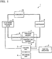
- FIG. 1 is a diagram showing a configuration of a refrigeration unit according to a first embodiment.
- the refrigeration unit 1 according to the first embodiment may be used as a refrigeration unit for transportation which is mounted on a truck, a train, an aircraft, or the like.
- the refrigeration unit 1 is not limited to the aspects described above, and may be used as a general refrigeration unit.
- the refrigeration unit 1 includes a control unit 2, a control interface 3, a recording unit 4, an electronic expansion valve 5, an evaporator 6, a pressure sensor 7, a temperature sensor 8, a compressor 9, and a condenser 10. As shown in FIG. 1 , the electronic expansion valve 5, the evaporator 6, the compressor 9, and the condenser 10 are connected sequentially in a loop shape using pipes through which a refrigerant passes to form a refrigeration cycle.
- the control unit 2 acquires one of a plurality of saturation temperature tables corresponding to different refrigerants from the recording unit 4, and controls an expansion valve opening degree of the electronic expansion valve in the refrigeration unit so that a predetermined degree of superheat can be obtained based on the acquired saturation temperature table. Also, a functional configuration of the control unit 2 will be described in more detail below with reference to FIG. 2 .
- the control interface 3 is a means for an operator to set the refrigeration unit, and provides the operator with a means for selecting the refrigerant.
- the control interface 3 may be implemented with an arbitrary user interface for communicating the intention of the operator to the control unit 2.
- the control interface 3 may be implemented as a physical switch such as a dip switch on a board, or as a touch sensor provided on a touch display.
- the operator can select any of available refrigerants on the control interface 3.
- the control unit 2 acquires a saturation temperature table corresponding to the selected refrigerant from the plurality of saturation temperature tables recorded in the recording unit 4.
- the recording unit 4 records a plurality of saturation temperature tables corresponding to different refrigerants.
- the saturation temperature table represents the gas side saturation temperature of the refrigerant with respect to each pressure.
- the control unit 2 acquires one from the plurality of saturation temperature tables recorded in the recording unit 4, and performs control of a degree of superheat based on the acquired saturation temperature table. Details of the saturation temperature table will be described in more detail below with reference to FIGS. 2 to 7 .
- the electronic expansion valve 5 is connected between the condenser 10 and the evaporator 6, and a high-pressure liquid refrigerant flows thereinto from the condenser 10.
- the electronic expansion valve 5 adjusts a flow rate or the like of the refrigerant to make the refrigerant passing in accordance with an opening degree thereof, thereby adjusting the pressure of the refrigerant after passing, and discharges a low pressure gas-liquid mixed refrigerant to the evaporator 6.
- the opening degree of the electronic expansion valve 5 is dynamically adjustable and is controlled by the control unit 2.
- the evaporator 6 is connected between the electronic expansion valve 5 and the compressor 9, and a low pressure refrigerant flows thereinto from the electronic expansion valve 5.
- the evaporator 6 has a function of evaporating the refrigerant expanded by the electronic expansion valve. Therefore, since all the refrigerant which was in a mixed state of a liquid phase and a gas phase is vaporized in the evaporator 6, heat exchange with the air is carried out due to heat absorption of the refrigerant. As a result, the air in a storage in which the refrigeration unit is installed is cooled.
- the refrigerant in which the liquid phase and gas phase are mixed becomes a completely vaporized refrigerant at an outlet of the evaporator 6. Therefore, in order to ensure that the refrigerant is discharged in a completely vaporized state, the evaporator 6 makes the refrigerant into superheated steam at a temperature higher than the gas side saturation temperature and then discharges it to the compressor 9 side.
- An ascending temperature of the superheated steam with respect to the gas side saturation temperature is generally called a "degree of superheat.”
- the pressure sensor 7 may be provided in a pipe or the like extending from the evaporator 6 to the compressor 9, and detects the pressure of the refrigerant at the outlet of the evaporator 6 (hereinafter referred to as the "outlet pressure").
- the pressure sensor 7 outputs the detected pressure to the control unit 2, and the control unit 2 uses the pressure detected by the pressure sensor 7 to calculate the degree of superheat.
- the temperature sensor 8 may be provided in a pipe or the like similarly extending from the evaporator 6 to the compressor 9, and detects the temperature of the refrigerant at the outlet of the evaporator 6 (hereinafter referred to as the "outlet temperature").
- the temperature sensor 8 outputs the detected pressure to the control unit 2, and the control unit 2 uses the temperature detected by the temperature sensor 8 in addition to the pressure to calculate the degree of superheat.
- the compressor 9 is connected between the evaporator 6 and the condenser 10, and a low-pressure gas refrigerant flows thereinto from the evaporator 6.
- the compressor 9 compresses the inflowing refrigerant to produce a high pressure gas refrigerant, and then discharges it to the condenser 10.
- the condenser 10 is connected between the compressor 9 and the electronic expansion valve 5, and a high-pressure gas refrigerant flows thereinto from the compressor 9.
- the condenser 10 releases heat from the high pressure gas refrigerant and discharges a high pressure liquid refrigerant to the electronic expansion valve 5.
- the refrigeration unit 1 cools, for example, an interior of a refrigerating storage mounted on a truck, train, aircraft, or the like using the above-described refrigeration cycle.
- the recording unit 4 it is possible for the recording unit 4 to record a plurality of saturation temperature tables corresponding to different refrigerants, and for the control unit 2 to acquire an appropriate one from among the plurality of saturation temperature tables, thereby performing appropriate control of the degree of superheat for different refrigerants.
- a more detailed functional configuration of the control unit 2 will be described below.
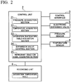
- FIG. 2 is a diagram showing a functional configuration of the control unit 2 according to the first embodiment.
- the control unit 2 includes a pressure acquisition section 21, a temperature acquisition section 22, a saturation temperature table acquisition section 23, an expansion valve control section 24, and a refrigerant selection signal acquisition section 25.
- the control unit 2 is a processor (a microcomputer) that takes charge of controlling the entire refrigeration unit 1, and operates in accordance with a program prepared in advance.
- the control unit 2 is also electrically coupled to the recording unit 4, the electronic expansion valve 5, the pressure sensor 7, and the temperature sensor 8.
- the recording unit 4 records saturation temperature tables corresponding to a plurality of refrigerants.
- the saturation temperature table represents the gas side saturation temperature for each pressure of the refrigerant.
- different refrigerants have different gas side saturation temperatures for each pressure.
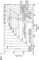
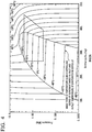
- FIGS. 3 and 4 boundaries of phase changes in the p-h diagram (Mollier diagram) of the refrigerants R404A and R452A are shown in FIGS. 3 and 4 .
- the saturation temperature table expresses the relationship between the pressure and the gas side saturation temperature in the graph as a table.
- the refrigeration cycle of the refrigeration unit on the p-h diagram is shown as a dotted line.
- the bottom side portion of a reverse trapezoidal shape in the refrigeration cycle shows the state change of the refrigerant in the evaporator.
- the refrigerant passes through the electronic expansion valve 5, it flows into the evaporator in a low pressure and low temperature state.
- the refrigerant changes from a mixed state of the liquid phase and the gas phase to a gas phase.
- the refrigerant is heated as much as the degree of superheat higher than the gas side saturation temperature and is discharged to the compressor 9 side.
- the arrow (1) shows the state of the evaporator outlet and the arrow (2) shows the state at the gas side saturation temperature.
- the degree of superheat is calculated as a value obtained by subtracting the gas side saturation temperature from the evaporator outlet temperature.
- the saturation temperature table is recorded in the recording unit 4 as a table as shown in FIG. 5 , for example.
- FIG. 5 illustrates, as examples, saturation temperature tables for three refrigerants, saturation temperature tables for any number of refrigerants may be recorded in the recording unit 4.
- the gas side saturation temperatures (T A1 , T A2 , and T A3 ) of the refrigerant are associated with respective pressures (P 1 , P 2 , and P 3 ).
- the saturation temperature table for the refrigerant B the gas side saturation temperatures (T B1 , T B2 , and T B3 ) of the refrigerant are associated with respective pressures (P 1 , P 2 , and P 3 ).
- the gas side saturation temperatures (T C1 , T C2 , and T C3 ) of the refrigerant are associated with respective pressures (P 1 , P 2 , and P 3 ).
- the gas side saturation temperatures are explicitly associated only with three pressures in FIG. 5 , this is merely an example and the gas side saturation temperatures can be associated with any number of pressures at any intervals.
- the saturation temperature table is assumed to be recorded in advance in the recording unit 4 at the time of manufacture. However, it may be recorded and updated at any time by acquiring data from a network via wireless or wired communication, or from another external recording medium as necessary.
- the pressure acquisition section 21 acquires the outlet pressure from the pressure sensor 7 that detects the pressure of the refrigerant at the outlet of the evaporator 6.
- the temperature acquisition section 22 acquires the outlet temperature from the temperature sensor 8 that detects the temperature of the refrigerant at the outlet of the evaporator 6.
- the pressure acquisition section 21 and the temperature acquisition section 22 can acquire measured values of the respective sensors continuously or at predetermined time intervals.
- the obtained outlet pressure and outlet temperature of the evaporator 6 are used by the expansion valve control section 24 to determine and control the degree of superheat.
- the refrigerant selection signal acquisition section 25 acquires a signal corresponding to the refrigerant selected by the operator in the control interface 3 from the control interface 3.
- the control interface 3 may be implemented in any form such as a physical switch on a board or a touch sensor on a touch display.
- the operator can select an intended refrigerant at the control interface 3, and the refrigerant selection signal acquisition section 25 acquires a signal reflecting the refrigerant selection of the operator.
- the saturation temperature table acquisition section 23 acquires one of the plurality of saturation temperature tables recorded in the recording unit 4.
- the saturation temperature table acquisition section 23 can select a corresponding one from the plurality of saturation temperature tables based on an initial setting or signals acquired by the refrigerant selection signal acquisition section.
- the expansion valve control section 24 controls the expansion valve opening degree of the electronic expansion valve 5 in the refrigeration unit to obtain a predetermined degree of superheat based on the saturation temperature table acquired by the saturation temperature table acquisition section 23, the outlet pressure acquired by the pressure acquisition section 21, and the outlet temperature acquired by the temperature acquisition section 22. This control of the degree of superheat will be described in more detail below.
- the refrigerant selection signal acquisition section 25 acquires the refrigerant selection signal from the control interface 3, and an appropriate saturation temperature table is selected based on the refrigerant selection signal.
- the control unit 2 may automatically determine a refrigerant to be used, and select an appropriate saturation temperature table based on the determination.
- the control unit 2 may include a refrigerant determination section 26 (not shown) that determines a refrigerant to be used for the refrigeration unit 1, instead of the refrigerant selection signal acquisition section 25.
- the saturation temperature table acquisition section 23 can select a corresponding one of the plurality of saturation temperature tables based on the determined refrigerant.
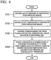
- FIG. 6 is a diagram showing a processing flow of the control unit 2 according to the first embodiment.
- the operator can select a refrigerant to be used through the control interface 3. For example, a situation in which a currently used refrigerant cannot be used when replacement of the refrigerant is required due to a failure or the like is assumed. In such a case, the operator selects settings corresponding to a newly replaced refrigerant on the control interface 3. As described above, the control interface 3 may be implemented into a user interface in any type that allows the operator to select a refrigerant. After such settings are made, the following processing flow may be started. It should be noted that the order of the processing steps described below is merely illustrated for ease of explanation, and the order of some processing steps may be changed or they may be executed in parallel.
- step S101 the control unit 2 acquires the outlet pressure of the evaporator 6 from the pressure sensor that detects the outlet pressure of the evaporator 6 in the refrigeration unit 1. Further, in step S102, the control unit 2 acquires the outlet temperature of the evaporator 6 from the temperature sensor that detects the outlet temperature of the evaporator 6. In order to control the degree of superheat of the refrigeration unit 1, acquisition of the outlet pressure and the outlet temperature may be performed continuously as long as the operation of the refrigeration unit 1 continues.
- step S103 the control unit 2 acquires a corresponding one from the plurality of saturation temperature tables recorded in the recording unit 4 in the refrigeration unit 1.
- the plurality of saturation temperature tables include saturation temperature tables corresponding to different refrigerants, and each saturation temperature table specifies the gas side saturation temperature for each pressure for a particular refrigerant.
- the control unit 2 may perform acquisition of the saturation temperature table by executing the steps of acquiring a signal indicating the refrigerant selected by the operator from the control interface 3 of the refrigeration unit 1 and selecting a corresponding saturation temperature table from the plurality of saturation temperature tables recorded in the recording unit 4 based on a signal indicating the selected refrigerant.
- the acquired saturation temperature table may be stored in a memory or the like in the processor constituting the control unit 2 and may be referred to at any time by the control unit 2.
- control unit 2 controls the expansion valve opening degree of the electronic expansion valve 5 in the refrigeration unit 1 to be able to obtain a predetermined degree of superheat based on the acquired saturation temperature table, the acquired outlet pressure, and the acquired outlet temperature.
- control unit 2 may first calculate the current degree of superheat. That is, the control unit 2 can determine what degree is the gas side saturation temperature with respect to the currently acquired outlet pressure of the evaporator 6 with reference to the acquired saturation temperature table. Also, the control unit 2 can determine the current degree of superheat by subtracting the determined gas side saturation temperature of the refrigerant from the acquired outlet temperature. In addition, the control unit 2 can control the expansion valve opening degree of the electronic expansion valve 5 so that the current degree of superheat is brought close to the predetermined degree of superheat. For example, by increasing the opening degree of the electronic expansion valve 5 above the present state, the pressure in the evaporator 6 can be lowered. As is apparent from FIGS.
- step S104 may be performed continuously as long as the operation of the refrigeration unit 1 continues.
- the degree of superheat is determined by determining the gas side saturation temperature from the saturation temperature table and measuring the outlet temperature of the evaporator 6.
- such a configuration makes it possible to control the degree of superheat more accurately as compared with the method of measuring an inlet temperature of the evaporator 6 as the gas side saturation temperature and calculating the degree of superheat from the difference between the inlet temperature and the outlet temperature.
- the refrigerant having the temperature glide characteristic has a problem that the inlet temperature of the evaporator 6 is different from the gas side saturation temperature of the refrigerant. Therefore, by calculating the gas side saturation temperature directly from the saturation temperature table as in the present invention, a more accurate degree of superheat can be obtained, and the control of the degree of superheat can be performed more accurately.
- the saturation temperature table corresponding to the refrigerant to be used can be selected, thereby making it possible to perform optimal controlling of the degree of superheat.
- the refrigeration unit has an allowable pressure, and this allowable pressure is derived from an allowable pressure of a refrigerant container or the like. Therefore, it is practically impossible for a refrigeration unit to be compatible with all refrigerants, and a refrigeration unit is compatible with a refrigerant having a predetermined pressure characteristic. Also, although a lubricating oil such as polyol ester (POE) oil is used for a refrigeration unit, a suitable refrigerant for each lubricating oil also exists.
- POE polyol ester
- a refrigeration unit is configured such that an operator can select a suitable refrigerant under predetermined conditions of the refrigeration unit.
- FIG. 7 is a diagram showing a further functional configuration of the control unit 2 and the recording unit 4, in addition to the functional configuration of the control unit 2 and the recording unit 4 shown in FIG. 2 .
- the control unit 2 and the recording unit 4 shown in FIG. 2 For ease of explanation, descriptions of each component of the control unit 2 shown in FIG. 2 are omitted in FIG. 7 .
- the recording unit 4 further records information on the allowable pressure of the refrigeration unit 1 (hereinafter referred to as “allowable pressure information”) and information on the lubricating oil to be used for the refrigeration unit 1 (hereinafter referred to as “lubricating oil information").
- the allowable pressure of the refrigeration unit 1 is determined in advance based on a design of the refrigerant container of the refrigeration unit 1 and other designs of the refrigeration unit 1.
- control unit 2 further includes a compatible refrigerant determination section 26, a compatible refrigerant information providing section 27, and a warning information providing section 28.
- the compatible refrigerant determination section 26 determines the refrigerant (hereinafter referred to as the "compatible refrigerant") suitable for the allowable pressure of the refrigeration unit 1 and the lubricating oil to be used for the refrigeration unit 1, among the refrigerants corresponding to the saturation temperature tables recorded in the recording unit 4, based on the allowable pressure information and the lubricant information recorded in the recording unit 4.
- the compatible refrigerant is determined based on both the allowable pressure information and the lubricant information in the present embodiment, the compatible refrigerant may be determined based on either information in other embodiments.
- the compatible refrigerant information providing section 27 provides information on the compatible refrigerant determined by the compatible refrigerant determination section 26 to the control interface 3.
- the control interface 3 includes a display
- by displaying the compatible refrigerant on the display only the compatible refrigerant can be selected by the operator.
- the control interface 3 is implemented with physical switches, it is possible to explicitly indicate a switch corresponding to the compatible refrigerant by turning on a lamp or the like, thereby informing the operator of the compatible refrigerant.
- the present invention is not limited to such an embodiment, and the control interface 3 may be configured to notify the operator of a compatible refrigerant in an arbitrary form by using the information on the compatible refrigerant.
- the warning information providing section 28 provides warning information to the control interface 3 when an incompatible refrigerant is selected in the control interface 3.
- the refrigerant selection signal acquisition section 25 shown in FIG. 2 acquires a signal indicating the refrigerant selected by the operator from the control interface 3.
- the warning information providing section 28 provides warning information to the control interface 3 when the selected refrigerant is other than the compatible refrigerant determined by the compatible refrigerant determination section 26. This configuration is particularly useful when the control interface 3 includes a physical switch such as a dip switch or the like provided on a substrate.
- control unit 2 can control not to execute controlling of the refrigeration unit 1 when an incompatible refrigerant is selected.
- the recording unit 4 may also record information on which refrigerant is ASHRAE safety grade A1 (non-toxic, noncombustible), and the control unit 2 may control the control interface 3 such that the operator can select only the refrigerant which is ASHRAE safety grade A1 (non-toxic, non-combustible).
- FIG. 8 is a diagram showing a processing flow of the control unit according to the second embodiment.
- the processing flow of FIG. 8 may be executed before the processing flow shown in FIG. 6 is started.
- step S201 the control unit 2 determines the compatible refrigerant of the refrigeration unit 1 among the refrigerants corresponding to the saturation temperature tables recorded in the recording unit 4 based on the allowable pressure information and the lubricant information recorded in the recording unit 4.
- step S202 the control unit 2 provides information on the determined compatible refrigerant to the control interface 3.
- the control interface 3 can notify the operator of the compatible refrigerant in an arbitrary manner using the received information on the compatible refrigerant.
- the control interface 3 includes a display, only the compatible refrigerant may be selectively displayed. In this case, since the operator can select only the compatible refrigerant, the following step S203 may be omitted and the process described in FIG. 6 may be continued.
- step S203 the control unit 2 receives a signal indicating the selection of the refrigerant from the control interface 3, and determines whether the selected refrigerant is included in the determined compatible refrigerant or not.
- step S203 that is, when the compatible refrigerant is selected in the control interface 3, the processing in the control unit 2 continues to the processing flow in step S101 shown in FIG. 6 .
- step S203 that is, when an incompatible refrigerant is selected in the control interface 3
- warning information is provided to the control interface 3 in step S204 to urge a provider to select a compatible refrigerant.
- the operator can reliably select the refrigerant suitable for the refrigeration unit without knowing the allowable pressure and the lubricating oil for the refrigeration unit, or other conditions concerning refrigerants. Therefore, it is possible to prevent the refrigeration unit from malfunctioning or the like resulting from using incompatible refrigerant.
- the processes of the control unit 2 described above are stored in a computer-readable recording medium in the form of a program.
- the above-described various processes are performed by reading and executing this program by the computer.
- the computer-readable recording medium refers to a magnetic disk, a magneto-optical disk, a CD-ROM, a DVD-ROM, a semiconductor memory, or the like.
- the computer program may be distributed to a computer via a communication line, and the computer receiving the distribution may run the program.
- the above program may be provided for executing a part of the functions described above. Further, it may be a so-called difference file (a difference program) which can realize the above-mentioned functions based on combinations with programs already recorded in a computer system. Furthermore, in another embodiment, the control unit 2 of the refrigeration unit 1 may be configured with one computer or a plurality of computers communicably connected.
- control device for the refrigeration unit the refrigeration unit, the control method for the refrigeration unit, and the program, controlling the degree of superheat suitable for refrigerants can be performed even when different refrigerants are used in the refrigeration unit. Accordingly, even in a situation where a refrigerant changing time and directivity are different in each country, refrigerants to be used can be selected while keeping the same design for machines. Thus, it is possible to cope with a plurality of refrigerants without hampering a cost reduction effect due to a mass production effect of the machines. Also, even when selection and concentration of alternative cooling progresses in the future, a drop-in use of refrigerants available at that time can be easily made.
Landscapes
- Engineering & Computer Science (AREA)
- Physics & Mathematics (AREA)
- Mechanical Engineering (AREA)
- Thermal Sciences (AREA)
- General Engineering & Computer Science (AREA)
- Air-Conditioning For Vehicles (AREA)
- Air Conditioning Control Device (AREA)
Applications Claiming Priority (1)
| Application Number | Priority Date | Filing Date | Title |
|---|---|---|---|
| JP2017218055A JP2019090552A (ja) | 2017-11-13 | 2017-11-13 | 制御装置、冷凍機、制御方法、およびプログラム |
Publications (2)
| Publication Number | Publication Date |
|---|---|
| EP3483531A2 true EP3483531A2 (de) | 2019-05-15 |
| EP3483531A3 EP3483531A3 (de) | 2019-07-31 |
Family
ID=64959077
Family Applications (1)
| Application Number | Title | Priority Date | Filing Date |
|---|---|---|---|
| EP18205477.5A Withdrawn EP3483531A3 (de) | 2017-11-13 | 2018-11-09 | Steuerungsvorrichtung, kältemaschine, steuerungsverfahren und programm |
Country Status (2)
| Country | Link |
|---|---|
| EP (1) | EP3483531A3 (de) |
| JP (1) | JP2019090552A (de) |
Cited By (2)
| Publication number | Priority date | Publication date | Assignee | Title |
|---|---|---|---|---|
| CN112629898A (zh) * | 2020-11-24 | 2021-04-09 | 珠海格力电器股份有限公司 | 基于制冷剂识别的通用控制方法及标准制冷设备 |
| WO2021115222A1 (zh) * | 2019-12-09 | 2021-06-17 | 杭州三花研究院有限公司 | 一种控制方法以及控制系统 |
Families Citing this family (2)
| Publication number | Priority date | Publication date | Assignee | Title |
|---|---|---|---|---|
| CN113237203B (zh) * | 2021-06-28 | 2023-03-28 | 广东美的白色家电技术创新中心有限公司 | 电子膨胀阀控制方法及相关设备 |
| CN113654280B (zh) * | 2021-08-06 | 2022-09-16 | 佛山市顺德区美的电子科技有限公司 | 空调器电子膨胀阀的控制方法、控制装置、空调器和介质 |
Citations (2)
| Publication number | Priority date | Publication date | Assignee | Title |
|---|---|---|---|---|
| JPS6136671A (ja) | 1984-07-26 | 1986-02-21 | 三洋電機株式会社 | 冷媒流量制御装置 |
| JP2017218055A (ja) | 2016-06-09 | 2017-12-14 | マツダ株式会社 | 運転支援装置 |
Family Cites Families (4)
| Publication number | Priority date | Publication date | Assignee | Title |
|---|---|---|---|---|
| JPH07253250A (ja) * | 1994-03-15 | 1995-10-03 | Toshiba Corp | 冷凍サイクル制御装置 |
| JPH08254363A (ja) * | 1995-03-15 | 1996-10-01 | Toshiba Corp | 空調制御装置 |
| US9234686B2 (en) * | 2013-03-15 | 2016-01-12 | Energy Recovery Systems Inc. | User control interface for heat transfer system |
| US9470445B2 (en) * | 2014-11-07 | 2016-10-18 | Emerson Climate Technologies, Inc. | Head pressure control |
-
2017
- 2017-11-13 JP JP2017218055A patent/JP2019090552A/ja active Pending
-
2018
- 2018-11-09 EP EP18205477.5A patent/EP3483531A3/de not_active Withdrawn
Patent Citations (2)
| Publication number | Priority date | Publication date | Assignee | Title |
|---|---|---|---|---|
| JPS6136671A (ja) | 1984-07-26 | 1986-02-21 | 三洋電機株式会社 | 冷媒流量制御装置 |
| JP2017218055A (ja) | 2016-06-09 | 2017-12-14 | マツダ株式会社 | 運転支援装置 |
Cited By (3)
| Publication number | Priority date | Publication date | Assignee | Title |
|---|---|---|---|---|
| WO2021115222A1 (zh) * | 2019-12-09 | 2021-06-17 | 杭州三花研究院有限公司 | 一种控制方法以及控制系统 |
| US12146692B2 (en) | 2019-12-09 | 2024-11-19 | Hangzhou Sanhua Research Institute Co., Ltd. | Control method and control system |
| CN112629898A (zh) * | 2020-11-24 | 2021-04-09 | 珠海格力电器股份有限公司 | 基于制冷剂识别的通用控制方法及标准制冷设备 |
Also Published As
| Publication number | Publication date |
|---|---|
| JP2019090552A (ja) | 2019-06-13 |
| EP3483531A3 (de) | 2019-07-31 |
Similar Documents
| Publication | Publication Date | Title |
|---|---|---|
| CN110234943B (zh) | 用于冷却系统的低充注检测系统 | |
| CN108027188B (zh) | 冷冻循环装置 | |
| US7343750B2 (en) | Diagnosing a loss of refrigerant charge in a refrigerant system | |
| JP5995990B2 (ja) | 冷凍装置 | |
| EP3004756B1 (de) | Kältekreislauf | |
| US9395112B2 (en) | Method for controlling operation of a vapour compression system in a subcritical and a supercritical mode | |
| JP6902390B2 (ja) | 冷凍サイクル装置 | |
| CN114654969A (zh) | 具有过热、过冷和制冷剂充注量控制的制冷系统 | |
| JP5511761B2 (ja) | 空気調和機 | |
| JP2008249239A (ja) | 冷却装置の制御方法、冷却装置および冷蔵倉庫 | |
| EP3306231A1 (de) | Steuerungsvorrichtung, kühlmittelkreislaufsystem, steuerungsverfahren und programm | |
| JP2019090552A (ja) | 制御装置、冷凍機、制御方法、およびプログラム | |
| JP2012211723A (ja) | 冷凍装置及び冷凍装置の冷媒漏れ検知方法 | |
| JP6890555B2 (ja) | 冷凍装置 | |
| JP2018141607A (ja) | 冷媒量判定装置、空気調和システム、冷媒量判定方法およびプログラム | |
| JP6008416B2 (ja) | 冷凍装置及び冷凍装置の冷媒漏れ検知方法 | |
| CN110914618A (zh) | 冷冻装置 | |
| JP6437120B2 (ja) | チリングユニット | |
| JP6095155B2 (ja) | 冷凍装置及び冷凍装置の冷媒漏れ検知方法 | |
| JP4009288B2 (ja) | フラッシュガスを検出するための方法と装置 | |
| JP5756919B2 (ja) | 冷凍装置 | |
| JP2007240105A (ja) | 環境試験装置及びその運転方法 | |
| JP2014129900A (ja) | 冷凍装置 | |
| US20240230180A1 (en) | Refrigeration system and method of operating a refrigeration system | |
| JP2005106314A (ja) | 冷凍装置 |
Legal Events
| Date | Code | Title | Description |
|---|---|---|---|
| PUAI | Public reference made under article 153(3) epc to a published international application that has entered the european phase |
Free format text: ORIGINAL CODE: 0009012 |
|
| STAA | Information on the status of an ep patent application or granted ep patent |
Free format text: STATUS: THE APPLICATION HAS BEEN PUBLISHED |
|
| AK | Designated contracting states |
Kind code of ref document: A2 Designated state(s): AL AT BE BG CH CY CZ DE DK EE ES FI FR GB GR HR HU IE IS IT LI LT LU LV MC MK MT NL NO PL PT RO RS SE SI SK SM TR |
|
| AX | Request for extension of the european patent |
Extension state: BA ME |
|
| PUAL | Search report despatched |
Free format text: ORIGINAL CODE: 0009013 |
|
| AK | Designated contracting states |
Kind code of ref document: A3 Designated state(s): AL AT BE BG CH CY CZ DE DK EE ES FI FR GB GR HR HU IE IS IT LI LT LU LV MC MK MT NL NO PL PT RO RS SE SI SK SM TR |
|
| AX | Request for extension of the european patent |
Extension state: BA ME |
|
| RIC1 | Information provided on ipc code assigned before grant |
Ipc: F25B 49/02 20060101AFI20190626BHEP |
|
| STAA | Information on the status of an ep patent application or granted ep patent |
Free format text: STATUS: REQUEST FOR EXAMINATION WAS MADE |
|
| 17P | Request for examination filed |
Effective date: 20200129 |
|
| RBV | Designated contracting states (corrected) |
Designated state(s): AL AT BE BG CH CY CZ DE DK EE ES FI FR GB GR HR HU IE IS IT LI LT LU LV MC MK MT NL NO PL PT RO RS SE SI SK SM TR |
|
| STAA | Information on the status of an ep patent application or granted ep patent |
Free format text: STATUS: EXAMINATION IS IN PROGRESS |
|
| 17Q | First examination report despatched |
Effective date: 20200323 |
|
| STAA | Information on the status of an ep patent application or granted ep patent |
Free format text: STATUS: THE APPLICATION HAS BEEN WITHDRAWN |
|
| 18W | Application withdrawn |
Effective date: 20200703 |