EP3483023A1 - Verfahren zur unterstützung des anfahrens für ein durch einen motor angetriebenes fahrzeug - Google Patents
Verfahren zur unterstützung des anfahrens für ein durch einen motor angetriebenes fahrzeug Download PDFInfo
- Publication number
- EP3483023A1 EP3483023A1 EP18202560.1A EP18202560A EP3483023A1 EP 3483023 A1 EP3483023 A1 EP 3483023A1 EP 18202560 A EP18202560 A EP 18202560A EP 3483023 A1 EP3483023 A1 EP 3483023A1
- Authority
- EP
- European Patent Office
- Prior art keywords
- engine
- speed
- torque
- control unit
- increase
- Prior art date
- Legal status (The legal status is an assumption and is not a legal conclusion. Google has not performed a legal analysis and makes no representation as to the accuracy of the status listed.)
- Withdrawn
Links
- 238000000034 method Methods 0.000 title claims abstract description 17
- 238000001514 detection method Methods 0.000 claims 1
- 238000010586 diagram Methods 0.000 description 3
- 230000001133 acceleration Effects 0.000 description 1
- 230000004913 activation Effects 0.000 description 1
- 230000001960 triggered effect Effects 0.000 description 1
Images


Classifications
-
- B—PERFORMING OPERATIONS; TRANSPORTING
- B60—VEHICLES IN GENERAL
- B60W—CONJOINT CONTROL OF VEHICLE SUB-UNITS OF DIFFERENT TYPE OR DIFFERENT FUNCTION; CONTROL SYSTEMS SPECIALLY ADAPTED FOR HYBRID VEHICLES; ROAD VEHICLE DRIVE CONTROL SYSTEMS FOR PURPOSES NOT RELATED TO THE CONTROL OF A PARTICULAR SUB-UNIT
- B60W30/00—Purposes of road vehicle drive control systems not related to the control of a particular sub-unit, e.g. of systems using conjoint control of vehicle sub-units
- B60W30/18—Propelling the vehicle
- B60W30/18009—Propelling the vehicle related to particular drive situations
- B60W30/18027—Drive off, accelerating from standstill
-
- B—PERFORMING OPERATIONS; TRANSPORTING
- B60—VEHICLES IN GENERAL
- B60W—CONJOINT CONTROL OF VEHICLE SUB-UNITS OF DIFFERENT TYPE OR DIFFERENT FUNCTION; CONTROL SYSTEMS SPECIALLY ADAPTED FOR HYBRID VEHICLES; ROAD VEHICLE DRIVE CONTROL SYSTEMS FOR PURPOSES NOT RELATED TO THE CONTROL OF A PARTICULAR SUB-UNIT
- B60W10/00—Conjoint control of vehicle sub-units of different type or different function
- B60W10/02—Conjoint control of vehicle sub-units of different type or different function including control of driveline clutches
-
- B—PERFORMING OPERATIONS; TRANSPORTING
- B60—VEHICLES IN GENERAL
- B60W—CONJOINT CONTROL OF VEHICLE SUB-UNITS OF DIFFERENT TYPE OR DIFFERENT FUNCTION; CONTROL SYSTEMS SPECIALLY ADAPTED FOR HYBRID VEHICLES; ROAD VEHICLE DRIVE CONTROL SYSTEMS FOR PURPOSES NOT RELATED TO THE CONTROL OF A PARTICULAR SUB-UNIT
- B60W10/00—Conjoint control of vehicle sub-units of different type or different function
- B60W10/04—Conjoint control of vehicle sub-units of different type or different function including control of propulsion units
- B60W10/06—Conjoint control of vehicle sub-units of different type or different function including control of propulsion units including control of combustion engines
-
- B—PERFORMING OPERATIONS; TRANSPORTING
- B60—VEHICLES IN GENERAL
- B60W—CONJOINT CONTROL OF VEHICLE SUB-UNITS OF DIFFERENT TYPE OR DIFFERENT FUNCTION; CONTROL SYSTEMS SPECIALLY ADAPTED FOR HYBRID VEHICLES; ROAD VEHICLE DRIVE CONTROL SYSTEMS FOR PURPOSES NOT RELATED TO THE CONTROL OF A PARTICULAR SUB-UNIT
- B60W30/00—Purposes of road vehicle drive control systems not related to the control of a particular sub-unit, e.g. of systems using conjoint control of vehicle sub-units
- B60W30/18—Propelling the vehicle
- B60W30/18009—Propelling the vehicle related to particular drive situations
- B60W30/18109—Braking
- B60W30/18118—Hill holding
-
- B—PERFORMING OPERATIONS; TRANSPORTING
- B60—VEHICLES IN GENERAL
- B60W—CONJOINT CONTROL OF VEHICLE SUB-UNITS OF DIFFERENT TYPE OR DIFFERENT FUNCTION; CONTROL SYSTEMS SPECIALLY ADAPTED FOR HYBRID VEHICLES; ROAD VEHICLE DRIVE CONTROL SYSTEMS FOR PURPOSES NOT RELATED TO THE CONTROL OF A PARTICULAR SUB-UNIT
- B60W30/00—Purposes of road vehicle drive control systems not related to the control of a particular sub-unit, e.g. of systems using conjoint control of vehicle sub-units
- B60W30/18—Propelling the vehicle
- B60W30/188—Controlling power parameters of the driveline, e.g. determining the required power
- B60W30/1882—Controlling power parameters of the driveline, e.g. determining the required power characterised by the working point of the engine, e.g. by using engine output chart
-
- F—MECHANICAL ENGINEERING; LIGHTING; HEATING; WEAPONS; BLASTING
- F16—ENGINEERING ELEMENTS AND UNITS; GENERAL MEASURES FOR PRODUCING AND MAINTAINING EFFECTIVE FUNCTIONING OF MACHINES OR INSTALLATIONS; THERMAL INSULATION IN GENERAL
- F16H—GEARING
- F16H59/00—Control inputs to control units of change-speed-, or reversing-gearings for conveying rotary motion
- F16H59/14—Inputs being a function of torque or torque demand
- F16H59/18—Inputs being a function of torque or torque demand dependent on the position of the accelerator pedal
-
- B—PERFORMING OPERATIONS; TRANSPORTING
- B60—VEHICLES IN GENERAL
- B60W—CONJOINT CONTROL OF VEHICLE SUB-UNITS OF DIFFERENT TYPE OR DIFFERENT FUNCTION; CONTROL SYSTEMS SPECIALLY ADAPTED FOR HYBRID VEHICLES; ROAD VEHICLE DRIVE CONTROL SYSTEMS FOR PURPOSES NOT RELATED TO THE CONTROL OF A PARTICULAR SUB-UNIT
- B60W50/00—Details of control systems for road vehicle drive control not related to the control of a particular sub-unit, e.g. process diagnostic or vehicle driver interfaces
- B60W2050/0001—Details of the control system
- B60W2050/0019—Control system elements or transfer functions
- B60W2050/0026—Lookup tables or parameter maps
-
- B—PERFORMING OPERATIONS; TRANSPORTING
- B60—VEHICLES IN GENERAL
- B60W—CONJOINT CONTROL OF VEHICLE SUB-UNITS OF DIFFERENT TYPE OR DIFFERENT FUNCTION; CONTROL SYSTEMS SPECIALLY ADAPTED FOR HYBRID VEHICLES; ROAD VEHICLE DRIVE CONTROL SYSTEMS FOR PURPOSES NOT RELATED TO THE CONTROL OF A PARTICULAR SUB-UNIT
- B60W2510/00—Input parameters relating to a particular sub-units
- B60W2510/02—Clutches
- B60W2510/0208—Clutch engagement state, e.g. engaged or disengaged
- B60W2510/0216—Clutch engagement rate
-
- B—PERFORMING OPERATIONS; TRANSPORTING
- B60—VEHICLES IN GENERAL
- B60W—CONJOINT CONTROL OF VEHICLE SUB-UNITS OF DIFFERENT TYPE OR DIFFERENT FUNCTION; CONTROL SYSTEMS SPECIALLY ADAPTED FOR HYBRID VEHICLES; ROAD VEHICLE DRIVE CONTROL SYSTEMS FOR PURPOSES NOT RELATED TO THE CONTROL OF A PARTICULAR SUB-UNIT
- B60W2510/00—Input parameters relating to a particular sub-units
- B60W2510/02—Clutches
- B60W2510/0275—Clutch torque
-
- B—PERFORMING OPERATIONS; TRANSPORTING
- B60—VEHICLES IN GENERAL
- B60W—CONJOINT CONTROL OF VEHICLE SUB-UNITS OF DIFFERENT TYPE OR DIFFERENT FUNCTION; CONTROL SYSTEMS SPECIALLY ADAPTED FOR HYBRID VEHICLES; ROAD VEHICLE DRIVE CONTROL SYSTEMS FOR PURPOSES NOT RELATED TO THE CONTROL OF A PARTICULAR SUB-UNIT
- B60W2510/00—Input parameters relating to a particular sub-units
- B60W2510/06—Combustion engines, Gas turbines
- B60W2510/0638—Engine speed
-
- B—PERFORMING OPERATIONS; TRANSPORTING
- B60—VEHICLES IN GENERAL
- B60W—CONJOINT CONTROL OF VEHICLE SUB-UNITS OF DIFFERENT TYPE OR DIFFERENT FUNCTION; CONTROL SYSTEMS SPECIALLY ADAPTED FOR HYBRID VEHICLES; ROAD VEHICLE DRIVE CONTROL SYSTEMS FOR PURPOSES NOT RELATED TO THE CONTROL OF A PARTICULAR SUB-UNIT
- B60W2540/00—Input parameters relating to occupants
- B60W2540/10—Accelerator pedal position
-
- B—PERFORMING OPERATIONS; TRANSPORTING
- B60—VEHICLES IN GENERAL
- B60W—CONJOINT CONTROL OF VEHICLE SUB-UNITS OF DIFFERENT TYPE OR DIFFERENT FUNCTION; CONTROL SYSTEMS SPECIALLY ADAPTED FOR HYBRID VEHICLES; ROAD VEHICLE DRIVE CONTROL SYSTEMS FOR PURPOSES NOT RELATED TO THE CONTROL OF A PARTICULAR SUB-UNIT
- B60W2540/00—Input parameters relating to occupants
- B60W2540/12—Brake pedal position
-
- B—PERFORMING OPERATIONS; TRANSPORTING
- B60—VEHICLES IN GENERAL
- B60W—CONJOINT CONTROL OF VEHICLE SUB-UNITS OF DIFFERENT TYPE OR DIFFERENT FUNCTION; CONTROL SYSTEMS SPECIALLY ADAPTED FOR HYBRID VEHICLES; ROAD VEHICLE DRIVE CONTROL SYSTEMS FOR PURPOSES NOT RELATED TO THE CONTROL OF A PARTICULAR SUB-UNIT
- B60W2710/00—Output or target parameters relating to a particular sub-units
- B60W2710/06—Combustion engines, Gas turbines
- B60W2710/0644—Engine speed
-
- B—PERFORMING OPERATIONS; TRANSPORTING
- B60—VEHICLES IN GENERAL
- B60W—CONJOINT CONTROL OF VEHICLE SUB-UNITS OF DIFFERENT TYPE OR DIFFERENT FUNCTION; CONTROL SYSTEMS SPECIALLY ADAPTED FOR HYBRID VEHICLES; ROAD VEHICLE DRIVE CONTROL SYSTEMS FOR PURPOSES NOT RELATED TO THE CONTROL OF A PARTICULAR SUB-UNIT
- B60W2710/00—Output or target parameters relating to a particular sub-units
- B60W2710/06—Combustion engines, Gas turbines
- B60W2710/0666—Engine torque
-
- F—MECHANICAL ENGINEERING; LIGHTING; HEATING; WEAPONS; BLASTING
- F02—COMBUSTION ENGINES; HOT-GAS OR COMBUSTION-PRODUCT ENGINE PLANTS
- F02N—STARTING OF COMBUSTION ENGINES; STARTING AIDS FOR SUCH ENGINES, NOT OTHERWISE PROVIDED FOR
- F02N11/00—Starting of engines by means of electric motors
- F02N11/08—Circuits or control means specially adapted for starting of engines
- F02N11/0851—Circuits or control means specially adapted for starting of engines characterised by means for controlling the engagement or disengagement between engine and starter, e.g. meshing of pinion and engine gear
-
- F—MECHANICAL ENGINEERING; LIGHTING; HEATING; WEAPONS; BLASTING
- F02—COMBUSTION ENGINES; HOT-GAS OR COMBUSTION-PRODUCT ENGINE PLANTS
- F02N—STARTING OF COMBUSTION ENGINES; STARTING AIDS FOR SUCH ENGINES, NOT OTHERWISE PROVIDED FOR
- F02N2200/00—Parameters used for control of starting apparatus
- F02N2200/02—Parameters used for control of starting apparatus said parameters being related to the engine
- F02N2200/022—Engine speed
-
- F—MECHANICAL ENGINEERING; LIGHTING; HEATING; WEAPONS; BLASTING
- F02—COMBUSTION ENGINES; HOT-GAS OR COMBUSTION-PRODUCT ENGINE PLANTS
- F02N—STARTING OF COMBUSTION ENGINES; STARTING AIDS FOR SUCH ENGINES, NOT OTHERWISE PROVIDED FOR
- F02N2200/00—Parameters used for control of starting apparatus
- F02N2200/10—Parameters used for control of starting apparatus said parameters being related to driver demands or status
- F02N2200/102—Brake pedal position
-
- F—MECHANICAL ENGINEERING; LIGHTING; HEATING; WEAPONS; BLASTING
- F02—COMBUSTION ENGINES; HOT-GAS OR COMBUSTION-PRODUCT ENGINE PLANTS
- F02N—STARTING OF COMBUSTION ENGINES; STARTING AIDS FOR SUCH ENGINES, NOT OTHERWISE PROVIDED FOR
- F02N2200/00—Parameters used for control of starting apparatus
- F02N2200/10—Parameters used for control of starting apparatus said parameters being related to driver demands or status
- F02N2200/103—Clutch pedal position
-
- F—MECHANICAL ENGINEERING; LIGHTING; HEATING; WEAPONS; BLASTING
- F02—COMBUSTION ENGINES; HOT-GAS OR COMBUSTION-PRODUCT ENGINE PLANTS
- F02N—STARTING OF COMBUSTION ENGINES; STARTING AIDS FOR SUCH ENGINES, NOT OTHERWISE PROVIDED FOR
- F02N2250/00—Problems related to engine starting or engine's starting apparatus
- F02N2250/06—Engine stall and related control features, e.g. for automatic restart
-
- F—MECHANICAL ENGINEERING; LIGHTING; HEATING; WEAPONS; BLASTING
- F16—ENGINEERING ELEMENTS AND UNITS; GENERAL MEASURES FOR PRODUCING AND MAINTAINING EFFECTIVE FUNCTIONING OF MACHINES OR INSTALLATIONS; THERMAL INSULATION IN GENERAL
- F16H—GEARING
- F16H59/00—Control inputs to control units of change-speed-, or reversing-gearings for conveying rotary motion
- F16H59/14—Inputs being a function of torque or torque demand
- F16H2059/147—Transmission input torque, e.g. measured or estimated engine torque
Definitions
- the invention relates to a method for assisting start-up for a motor-driven vehicle having a start-stop system which is braked by operation of a brake pedal with a main clutch subject to a modulating pressure, with an accelerator pedal for manually setting a speed of the engine and with a motor control unit for controlling the operation of the engine.
- the driver In a starting operation, the driver must manually increase the engine speed or torque to allow the engine to be operated under load, e.g. not stalled during a start on the mountain. Otherwise, the vehicle could roll back and drive onto other vehicles.
- the object of the invention is therefore to provide a method for assisting the startup for a vehicle driven by a motor vehicle of the type mentioned, by which the engine is not stalled when starting under load.
- This design automatically detects whether the speed must be raised during the starting process, so that a stalling of the engine can be prevented. The driver then no longer has to intervene manually, since, if necessary, an automatic speed increase takes place during a starting process.
- step 1 the method for assisting the startup for a motor-driven vehicle with a start-stop system is triggered in step 1 that after a start-stop operation, a previously actuated brake pedal of a brake released, so the brake is released ,
- step 2 from a stored in an engine control unit of the engine characteristic of the modulation pressure over the time of a main clutch ( FIG. 2 ) determines the modulation pressure of a main clutch.
- a current modulation pressure of 8 bar is detected.
- a step 3 from the determined modulation pressure of 8 bar by means of a characteristic curve of the torque stored in the engine control unit of the engine above the modulation pressure ( FIG. 3 ) determines the maximum transmissible torque of the engine, which in the present example is 550 Nm.
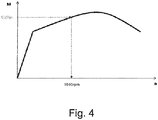
- a characteristic of the torque of the motor stored in the engine control unit of the engine over the engine speed is then (in FIG. FIG. 4 ) determines the speed of the motor required for the maximum transmissible torque of the motor. This is at a determined torque of 550 Nm, a speed of 1500 rpm.
- step 5 it is checked whether the required torque of 550 Nm is greater or less than the torque available at the current speed of 1500 rpm.
- step 7 If the required torque of 550 Nm is greater than the torque available at the current speed of 1500 rpm, it is checked in a step 7 whether the required speed request is greater or less than the requested speed corresponding to the position of the gas pedal.
- step 8 by the engine control unit the speed of the engine raised to the determined speed requirement of the engine to provide the required torque.
- the engine speed is raised in a step 9 by the engine control unit to a maximum of the speed which is predetermined by the driver by means of the accelerator pedal position. This does not lead to an independent acceleration of the vehicle.
- the engine speed is thus adapted during the startup so that the currently transmissible torque of the engine is available from the main clutch at any time.
Landscapes
- Engineering & Computer Science (AREA)
- Mechanical Engineering (AREA)
- Transportation (AREA)
- Chemical & Material Sciences (AREA)
- Combustion & Propulsion (AREA)
- Automation & Control Theory (AREA)
- General Engineering & Computer Science (AREA)
- Control Of Vehicle Engines Or Engines For Specific Uses (AREA)
- Hybrid Electric Vehicles (AREA)
- Control Of Driving Devices And Active Controlling Of Vehicle (AREA)
- Hydraulic Clutches, Magnetic Clutches, Fluid Clutches, And Fluid Joints (AREA)
Abstract
Die Erfindung bezieht sich auf ein Verfahren zur Unterstützung des Anfahrens für ein durch einen Motor angetriebenes Fahrzeug mit einem Start-Stopp-System, das durch Betätigung eines Bremspedals bremsbar ist, mit einer von einem Modulationsdruck beaufschlagbaren Hauptkupplung, mit einem Gaspedal zur manuellen Einstellung einer Drehzahl des Motors und mit einer Motorsteuereinheit zur Steuerung des Betriebs des Motors, gekennzeichnet durch folgende Schritte,
- erfassen des Loslassens des Bremspedals nach einem Start-Stop-Vorgang,
- ermitteln des Modulationsdrucks der Hauptkupplung,
- ermitteln eines benötigten Drehmoments aus dem ermittelten Modulationsdruck anhand einer gespeicherten Modulationsdruck - Drehmoment-Kennlinie,
- ermitteln der benötigten Drehzahlanforderung des Motors aus dem ermittelten benötigten Drehmoment anhand einer gespeicherten Drehmoment-Kennlinie des Motors,
- abfragen, ob die benötigte Drehzahlanforderung größer ist als das verfügbare Drehmoment bei der aktuellen Motordrehzahl des Motors,
- wenn nein, dann keine Ansteuerung zur Erhöhung der Drehzahl des Motors,
- wenn ja Abfrage, ob die benötigte Drehzahlanforderung größer ist, als die angeforderte Drehzahl entsprechend der Stellung des Gaspedals,
- wenn nein, dann anheben der Drehzahl des Motors durch die Motorsteuereinheit auf die ermittelte Drehzahlanforderung des Motors,
- wenn ja, dann anheben der Drehzahl des Motors durch die Motorsteuereinheit auf maximal die am Gaspedal eingestellte Drehzahl des Motors.
Description
- Die Erfindung bezieht sich auf ein Verfahren zur Unterstützung des Anfahrens für ein durch einen Motor angetriebenes Fahrzeug mit einem Start-Stopp-System, das durch Betätigung eines Bremspedals bremsbar ist, mit einer von einem Modulationsdruck beaufschlagbaren Hauptkupplung, mit einem Gaspedal zur manuellen Einstellung einer Drehzahl des Motors und mit einer Motorsteuereinheit zur Steuerung des Betriebs des Motors.
- Bei einem Anfahrvorgang muß der Fahrer die Motordrehzahl bzw. das Motordrehmoment manuell erhöhen, damit der Motor unter Last wie z.B. bei einem Anfahrvorgang am Berg nicht abgewürgt wird. Das Fahrzeug könnte sonst zurückrollen und auf andere Fahrzeuge auffahren.
- Aufgabe der Erfindung ist es daher ein Verfahren zur Unterstützung des Anfahrens für ein durch einen Motor angetriebenes Fahrzeug der eingangs genannten Art zu schaffen, durch das der Motor bei einem Anfahren unter Last nicht abgwürgt wird.
- Diese Aufgabe wird erfindungsgemäß durch folgende Schritte gelöst,
- erfassen des Loslassens des Bremspedals nach einem Start-Stop-Vorgang,
- ermitteln des Modulationsdrucks der Hauptkupplung,
- ermitteln eines benötigten Drehmoments aus dem ermittelten Modulationsdruck anhand einer gespeicherten Modulationsdruck - Drehmoment-Kennlinie,
- ermitteln der benötigten Drehzahlanforderung des Motors aus dem ermittelten benötigten Drehmoment anhand einer gespeicherten Drehmoment-Kennlinie des Motors,
- abfragen, ob die benötigte Drehzahlanforderung größer ist als das verfügbare Drehmoment bei der aktuellen Motordrehzahl des Motors,
- wenn nein, dann keine Ansteuerung zur Erhöhung der Drehzahl des Motors,
- wenn ja Abfrage, ob die benötigte Drehzahlanforderung größer ist, als die angeforderte Drehzahl entsprechend der Stellung des Gaspedals,
- wenn nein, dann anheben der Drehzahl des Motors durch die Motorsteuereinheit auf die ermittelte Drehzahlanforderung des Motors,
- wenn ja, dann anheben der Drehzahl des Motors durch die Motorsteuereinheit auf maximal die am Gaspedal eingestellte Drehzahl des Motors.
- Durch diese Ausbildung wird automatisch erkannt, ob die Drehzahl beim Anfahrvorgang angehoben werden muß, damit ein Abwürgen des Motors verhindert werden kann. Der Fahrer muß dann nicht mehr manuell eingreifen, da, wenn erforderlich, eine automatische Drehzahlerhöhung bei einem Anfahrvorgang erfolgt.
- Dabei kann in einfacher Weise das Erfassen des Loslassens des Bremspedals durch das Öffnen eines Bremslichtschalters eines Bremslichts erfolgen.
- Ein Ausführungsbeispiel der Erfindung ist in der Zeichnung dargestellt und wird im Folgenden näher beschrieben. Es zeigen:
- Figur 1
- ein Programmablaufplan eines Verfahrens zur Unterstützung des Anfahrens für ein durch einen Motor angetriebenes Fahrzeug mit einem Start-Stopp-System
- Figur 2
- ein Diagramm der Kennlinie des Modulationsdruckes über der Zeit einer Hauptkupplung des Verfahrens nach
Figur 1 - Figur 3
- ein Diagramm der Kennlinie des Drehmoments eines Motors über dem Modulationsdruck nach
Figur 2 - Figur 4
- ein Diagramm der Kennlinie des Drehmoments des Motors über der Drehzahl Motors des Verfahrens nach
Figur 1 . - Nach dem in
Figur 1 dargestellten Programmlaufplan wird das Verfahren zur Unterstützung des Anfahrens für ein durch einen Motor angetriebenes Fahrzeug mit einem Start-Stopp-System dadurch in Schritt 1 ausgelöst, daß nach einem Start-Stopp-Vorgang ein vorher betätigtes Bremspedal einer Bremse losgelassen, also die Bremse gelöst wird. - Ist das Loslassen des Bremspedals erfaßt worden, wird in einem Schritt 2 aus einer in einer Motorsteuereinheit des Motors gespeicherten Kennlinie des Modulationsdruckes über der Zeit einer Hauptkupplung (
Figur 2 ) der Modulationsdruck einer Hauptkupplung ermittelt. Im vorliegenden Beispiel wird ein aktueller Modulationsdruck von 8 bar erfaßt. - Anschließend wird in einem Schritt 3 aus dem ermittelten Modulationsdruck von 8 bar anhand einer in der Motorsteuereinheit des Motors gespeicherten Kennlinie des Drehmoments über dem Modulationsdruck (
Figur 3 ) das maximal übertragbare Drehmoment des Motors ermittelt, was im vorliegenden Beispiel 550 Nm beträgt. - In einem Schritt 4 wird dann aus einer in der Motorsteuereinheit des Motors gespeicherten Kennlinie des Drehmoments des Motors über der Drehzahl Motors (
Figur 4 ) die Drehzahl des Motors ermittelt, die für das maximal übertragbare Drehmoment des Motors erforderlich ist. Dies ist bei einem ermittelten Drehmoment von 550 Nm eine Drehzahl von 1500 rpm. - Nun wird in einem Schritt 5 überprüft, ob das erforderliche Drehmoment von 550 Nm größer oder kleiner ist als das bei der aktuellen Drehzahl von 1500 rpm verfügbare Drehmoment.
- Ist das erforderliche Drehmoment von 550 Nm kleiner ist als das bei der aktuellen Drehzahl von 1500 rpm verfügbare Drehmoment, so erfolgt in einem Schritt 6 keine Ansteuerung des Motors durch die Motorsteuereinheit zur einer Erhöhung der Drehzahl des Motors.
- Ist das erforderliche Drehmoment von 550 Nm größer als das bei der aktuellen Drehzahl von 1500 rpm verfügbare Drehmoment, so wird in einem Schritt 7 überprüft, ob die benötigte Drehzahlanforderung größer oder kleiner ist, als die angeforderte Drehzahl entsprechend der Stellung des Gaspedals.
- Ist die benötigte Drehzahlanforderung kleiner ist, als die angeforderte Drehzahl entsprechend der Stellung des Gaspedals, so wird in einem Schritt 8 durch die Motorsteuereinheit die Drehzahl des Motors auf die ermittelte Drehzahlanforderung des Motors angehoben um das geforderte Drehmoment bereit zu stellen.
- Ist die benötigte Drehzahlanforderung größer, als die angeforderte Drehzahl entsprechend der Stellung des Gaspedals, so wird in einem Schritt 9 durch die Motorsteuereinheit die Motordrehzahl maximal auf die Drehzahl angehoben, die von dem Fahrer mittels der Gaspedalstellung vorgegeben ist. Damit kommt es nicht zu einem eigenständigen Beschleunigen des Fahrzeugs.
- Durch das erfindungsgemäße Verfahren wird während des Anfahrvorgangs somit die Motordrehzahl so angepaßt, daß das von der Hauptkupplung zu jedem Zeitpunkt das aktuell übertragbare Drehmoment des Motors zur Verfügung steht.
-
- 1
- Schritt 1
- 2
- Schritt 2
- 3
- Schritt 3
- 4
- Schritt 4
- 5
- Schritt 5
- 6
- Schritt 6
- 7
- Schritt 7
- 8
- Schritt 8
- 9
- Schritt 9
Claims (2)
- Verfahren zur Unterstützung des Anfahrens für ein durch einen Motor angetriebenes Fahrzeug mit einem Start-Stopp-System, das durch Betätigung eines Bremspedals bremsbar ist, mit einer von einem Modulationsdruck beaufschlagbaren Hauptkupplung, mit einem Gaspedal zur manuellen Einstellung einer Drehzahl des Motors und mit einer Motorsteuereinheit zur Steuerung des Betriebs des Motors, gekennzeichnet durch folgende Schritte,- erfassen des Loslassens des Bremspedals nach einem Start-Stop-Vorgang,- ermitteln des Modulationsdrucks der Hauptkupplung,- ermitteln eines benötigten Drehmoments aus dem ermittelten Modulationsdruck anhand einer gespeicherten Modulationsdruck - Drehmoment-Kennlinie,- ermitteln der benötigten Drehzahlanforderung des Motors aus dem ermittelten benötigten Drehmoment anhand einer gespeicherten Drehmoment-Kennlinie des Motors,- abfragen, ob die benötigte Drehzahlanforderung größer ist als das verfügbare Drehmoment bei der aktuellen Motordrehzahl des Motors,- wenn nein, dann keine Ansteuerung zur Erhöhung der Drehzahl des Motors,- wenn ja Abfrage, ob die benötigte Drehzahlanforderung größer ist, als die angeforderte Drehzahl entsprechend der Stellung des Gaspedals,- wenn nein, dann anheben der Drehzahl des Motors durch die Motorsteuereinheit auf die ermittelte Drehzahlanforderung des Motors,- wenn ja, dann anheben der Drehzahl des Motors durch die Motorsteuereinheit auf maximal die am Gaspedal eingestellte Drehzahl des Motors.
- Verfahren nach Anspruch 1, dadurch gekennzeichnet, dass das Erfassen des Loslassens des Bremspedals durch das Öffnen eines Bremslichtschalters eines Bremslichts erfolgt.
Applications Claiming Priority (1)
| Application Number | Priority Date | Filing Date | Title |
|---|---|---|---|
| DE102017219971.7A DE102017219971A1 (de) | 2017-11-09 | 2017-11-09 | Verfahren zur Unterstützung des Anfahrens für ein durch einen Motor angetriebenes Fahrzeug |
Publications (1)
| Publication Number | Publication Date |
|---|---|
| EP3483023A1 true EP3483023A1 (de) | 2019-05-15 |
Family
ID=64017313
Family Applications (1)
| Application Number | Title | Priority Date | Filing Date |
|---|---|---|---|
| EP18202560.1A Withdrawn EP3483023A1 (de) | 2017-11-09 | 2018-10-25 | Verfahren zur unterstützung des anfahrens für ein durch einen motor angetriebenes fahrzeug |
Country Status (3)
| Country | Link |
|---|---|
| US (1) | US20190136817A1 (de) |
| EP (1) | EP3483023A1 (de) |
| DE (1) | DE102017219971A1 (de) |
Families Citing this family (3)
| Publication number | Priority date | Publication date | Assignee | Title |
|---|---|---|---|---|
| CN110594030B (zh) * | 2019-09-29 | 2022-04-05 | 潍柴动力股份有限公司 | 一种发动机冷启动方法及装置 |
| US11220990B2 (en) * | 2019-11-29 | 2022-01-11 | Hyundai Motor Company | Method and device for controlling start of vehicle |
| CN111946811B (zh) * | 2020-07-23 | 2021-07-06 | 东风汽车集团有限公司 | 汽车油门特性设计方法、系统及存储介质 |
Citations (5)
| Publication number | Priority date | Publication date | Assignee | Title |
|---|---|---|---|---|
| US3857302A (en) * | 1973-06-25 | 1974-12-31 | Caterpillar Tractor Co | Transmission and speed controlled lock-up clutch |
| EP0601728A1 (de) * | 1992-12-09 | 1994-06-15 | Eaton Corporation | Steuerung für Betriebsarten einer Kupplung |
| DE19632621C1 (de) * | 1996-08-13 | 1997-11-20 | Daimler Benz Ag | Automatisch steuerbare Kupplung |
| WO2010047652A1 (en) * | 2008-10-21 | 2010-04-29 | Scania Cv Ab (Publ) | Method, arrangement and computer program product for control of engine speed during a starting phase of a vehicle |
| EP2913503A1 (de) * | 2012-10-25 | 2015-09-02 | Aisin Seiki Kabushiki Kaisha | Antriebsvorrichtung für ein fahrzeug |
Family Cites Families (1)
| Publication number | Priority date | Publication date | Assignee | Title |
|---|---|---|---|---|
| WO2002090159A1 (de) * | 2001-05-09 | 2002-11-14 | Continental Teves Ag & Co. Ohg | Verfahren zum halten eines fahrzeugs an einem hang und anfahrhilfe zum halten eines fahrzeugs an einem hang |
-
2017
- 2017-11-09 DE DE102017219971.7A patent/DE102017219971A1/de not_active Ceased
-
2018
- 2018-10-25 EP EP18202560.1A patent/EP3483023A1/de not_active Withdrawn
- 2018-11-08 US US16/183,799 patent/US20190136817A1/en not_active Abandoned
Patent Citations (5)
| Publication number | Priority date | Publication date | Assignee | Title |
|---|---|---|---|---|
| US3857302A (en) * | 1973-06-25 | 1974-12-31 | Caterpillar Tractor Co | Transmission and speed controlled lock-up clutch |
| EP0601728A1 (de) * | 1992-12-09 | 1994-06-15 | Eaton Corporation | Steuerung für Betriebsarten einer Kupplung |
| DE19632621C1 (de) * | 1996-08-13 | 1997-11-20 | Daimler Benz Ag | Automatisch steuerbare Kupplung |
| WO2010047652A1 (en) * | 2008-10-21 | 2010-04-29 | Scania Cv Ab (Publ) | Method, arrangement and computer program product for control of engine speed during a starting phase of a vehicle |
| EP2913503A1 (de) * | 2012-10-25 | 2015-09-02 | Aisin Seiki Kabushiki Kaisha | Antriebsvorrichtung für ein fahrzeug |
Also Published As
| Publication number | Publication date |
|---|---|
| DE102017219971A1 (de) | 2019-05-09 |
| US20190136817A1 (en) | 2019-05-09 |
Similar Documents
| Publication | Publication Date | Title |
|---|---|---|
| US10486660B2 (en) | Method and apparatus for operating an electromotive parking brake of a motor vehicle, and motor vehicle | |
| DE10392775B4 (de) | Antriebsstrang und Verfahren zum Steuern und/oder Regeln eines Antriebsstrangs | |
| DE102008030898B4 (de) | Steuereinrichtung für ein Kraftfahrzeug mit Verbrennungsmotor und Stopp-Start-Einrichtung | |
| EP1343667B1 (de) | Verfahren und system zur anfahrunterstützung eines kraftfahrzeuges | |
| EP3483023A1 (de) | Verfahren zur unterstützung des anfahrens für ein durch einen motor angetriebenes fahrzeug | |
| EP3044056A1 (de) | Fahrassistenzsystem mit gesteigerter ausfallsicherheit und verfügbarkeit | |
| WO2008058507A1 (de) | Verfahren zum anfahren oder halten eines fahrzeuges am berg | |
| EP2203334B1 (de) | Anfahrassistenzsystem mit variabler bedingung für das lösen der bremse | |
| WO2017108305A1 (de) | Verfahren zum betreiben eines kraftfahrzeugs | |
| DE102013215101A1 (de) | Verfahren und Vorrichtung zur Ankupplung eines Verbrennungsmotors bei einem Verzögerungsvorgang | |
| DE102016212072A1 (de) | Verbesserte Start Stopp-Automatik eines motorgetriebenen Fahrzeugs mit handgeschaltetem Getriebe | |
| DE10248813A1 (de) | Verfahren für die Steuerung einer Rollsperre für ein Fahrzeug | |
| DE102009053021A1 (de) | Kriechvorgang | |
| DE102011004425A1 (de) | Schätzen des Status einer Ampelanlage | |
| EP1022459B1 (de) | Verfahren beim Anlassen des Motors eines Fahrzeugs | |
| DE10238870A1 (de) | Verfahren zum Durchführen eines selbsttätigen Bremsvorgangs für ein Kraftfahrzeug sowie Kraftfahrzeug | |
| WO2002090158A1 (de) | Verfahren zum unterstützen des anfahrens eines fahrzeugs an einem hang | |
| WO2011015179A1 (de) | Verfahren zur steuerung eines kriechvorgangs eines kraftfahrzeugs | |
| WO2004083627A1 (de) | Verfahren zur steuerung einer brennkraftmaschine | |
| WO2013110676A2 (de) | Verfahren zum betreiben eines verbrennungsmotors | |
| EP2648948B1 (de) | Verfahren zum lösen einer feststellbremse bei einem anfahrvorgang | |
| DE102015209973B4 (de) | Start-Stopp-Einrichtung zum Einleiten eines automatischen Abschaltvorgangs einer Antriebsmaschine | |
| DE102008037809A1 (de) | Verfahren und Vorrichtung zum Betrieb einer elektrischen Parkbremse | |
| EP1630459B1 (de) | Verfahren zum Regeln eines Schaltvorgangs bei einem automatisierten Schaltgetriebe | |
| WO2004082977A1 (de) | Verfahren für eine hillholder-einrichtung bei einem kraftfahrzeug |
Legal Events
| Date | Code | Title | Description |
|---|---|---|---|
| PUAI | Public reference made under article 153(3) epc to a published international application that has entered the european phase |
Free format text: ORIGINAL CODE: 0009012 |
|
| AK | Designated contracting states |
Kind code of ref document: A1 Designated state(s): AL AT BE BG CH CY CZ DE DK EE ES FI FR GB GR HR HU IE IS IT LI LT LU LV MC MK MT NL NO PL PT RO RS SE SI SK SM TR |
|
| AX | Request for extension of the european patent |
Extension state: BA ME |
|
| STAA | Information on the status of an ep patent application or granted ep patent |
Free format text: STATUS: THE APPLICATION IS DEEMED TO BE WITHDRAWN |
|
| 18D | Application deemed to be withdrawn |
Effective date: 20191116 |