EP3482857B1 - Vorrichtung und verfahren für die profilbearbeitung - Google Patents
Vorrichtung und verfahren für die profilbearbeitung Download PDFInfo
- Publication number
- EP3482857B1 EP3482857B1 EP18205045.0A EP18205045A EP3482857B1 EP 3482857 B1 EP3482857 B1 EP 3482857B1 EP 18205045 A EP18205045 A EP 18205045A EP 3482857 B1 EP3482857 B1 EP 3482857B1
- Authority
- EP
- European Patent Office
- Prior art keywords
- profile
- web
- holding
- holding device
- connecting element
- Prior art date
- Legal status (The legal status is an assumption and is not a legal conclusion. Google has not performed a legal analysis and makes no representation as to the accuracy of the status listed.)
- Active
Links
Images

Classifications
-
- B—PERFORMING OPERATIONS; TRANSPORTING
- B23—MACHINE TOOLS; METAL-WORKING NOT OTHERWISE PROVIDED FOR
- B23C—MILLING
- B23C3/00—Milling particular work; Special milling operations; Machines therefor
- B23C3/12—Trimming or finishing edges, e.g. deburring welded corners
- B23C3/128—Trimming or finishing edges of doors and windows
Definitions
- the invention relates to a method, according to the preamble of patent claim 1, for machining the end region of a plastic profile with a device for machining the end region of a plastic profile, in particular a profile for the production of a door or window frame, wherein the device has a support surface for the profile and a holding device for the profile, by means of which the profile is held on the support surface.
- the device described at the beginning is used in the state of the art to prepare plastic profiles from which door or window frames are made before the welding process. This often involves exact positioning and alignment of the miter surfaces, as this precise preparation has a positive effect on the welding result in terms of processing time and the resulting strength.
- the end area is the area of the plastic profile that extends from the end of the plastic profile a certain distance into the middle of the profile.
- the length of the piece depends, for example, on the miter angle at which the profiles are to be processed.
- the end area is usually a few centimeters.
- the device described at the beginning is often used to process plastic hollow chamber profiles. These are not solid material profiles; the hollow chamber profiles used are characterized by better insulation.
- the individual hollow chambers are separated from one another by longitudinal profile webs, and the profile is also limited on its outside by external profile webs.
- the device In order to fix the profile sufficiently during processing, the device is provided with a support surface on which the profile is placed and held by a holding device.
- a holding device can be considered to be, for example, a hold-down device or clamp, without, however, wishing to limit the subject matter of this invention to this.
- the (minimum) task of the holding device is to fix the profile in the device during processing.
- the US 2008083193 A1 discloses a method according to the preamble of patent claim 1 and in this regard deals with a system for processing window frames that have already been welded.
- This system comprises a device with a holding device that has at least one connecting element that interacts with the outer profile web of a profile of the frame.
- a system for processing window frames is also known.
- This document discloses a device with a holding device in which a connecting element interacts with an outer profile web.
- the EP 3072615 A1 teaches a milling head that uses an air current to remove chips when milling profiles.
- a device with a holding device is also disclosed, in which a holding device acts on a profile with at least one connecting element.
- the US 4102374 A discloses a device for producing corner elements from plastic profiles. This publication is not directly related to the production of window frames, but does disclose a device with a holding device for plastic profiles.
- the GB 2283193 A discloses a profile cutting device for welding joints of plastic profiles.
- the WO 97/11820 A1 shows a multifunctional work table system with a vertical screw clamp.
- the invention therefore aims to improve this state of the art.
- the disclosure includes a device as described above, wherein the holding device has at least one connecting element which cooperates with the outer profile web of the profile in a holding manner.
- the proposal according to the invention ensures that the profile webs that are important for the external design are positioned exactly during processing, thus enabling precise processing in relation to this external profile web. Dimensional tolerances typical of the plastic profile or other material properties that are negative for processing are overcome by the proposal according to the invention.
- the proposal according to the invention leads to significantly better machining results when machining the end area. Machining is carried out in such a way that the outer profile web remains standing. The profile webs inside the profile, which are parallel but also at right angles or running diagonally to the outer profile web, are removed. This processing leads to a destabilization of the outer profile web, which is counteracted by the fixation by the inventive proposal and thus supports and holds this outer profile web during processing.
- the inventive proposal is advantageous and avoids waste production.
- the holding device is arranged on or in the support surface.
- the holding device thus also supports the function of the support surface, because the holding device fixes the profile on the support surface.
- the invention also includes the use of several holding devices, possibly also acting differently, whereby, for example, the holding device, which is equipped with a connecting element, interacts with a holding device designed as a tensioner or hold-down device.
- the holding device is designed in the form of a plate.
- a plate-like design is characterized by the fact that the cover surface, seen in plan view, is relatively large and the holding device has a relatively small thickness. The cover surface is limited by several side edges on which the connecting elements are provided.
- the plate-like design thus cleverly combines a narrow construction with high stability, since a large number of individual connecting elements or one connecting element can be arranged along a long stretch on the side edges. This means that the external profile web is held along as long a stretch as possible, which leads to a high level of process reliability.
- the holding device has two long sides, the long sides each carry at least one connecting element and the long sides form an angle to each other, preferably a right angle, which corresponds to the inner angle of the door or window frame to be produced.
- the arrangement is cleverly chosen so that with one clamping process two or at least more Profiles are held by the holding device. Since the clamping process is followed by machining, it is clever to choose the arrangement so that at least two or more profiles can be machined simultaneously with one machining step.
- the proposal therefore supports effective, cost-saving machining.
- the connecting element holds the profile web by positive locking and/or frictional locking.
- the connecting element is designed as a retaining tooth protruding from the holding device.
- the connecting element is already formed from one retaining tooth.
- the proposal also includes variants with more than one retaining tooth, for example two, three, four or even more retaining teeth.
- the connecting element can be designed as a retaining edge.
- the retaining edge cleverly extends over a larger area of the long side and engages the profile web over a larger area.
- the two variants described above are preferred examples for the realization of a positive connection between the connecting element and the profile web.
- the profile web is pushed under the protruding retaining tooth or retaining edge and thus held in place.
- they can also be used in a force-fitting concept.
- the holding device is moved together with the connecting element, preferably in a relative movement parallel to the longitudinal extension of the profile, against the front side of the profile.
- the front side or tip of the connecting element facing the profile is pressed/moved against the profile with force.
- the proposal disclosed also includes a solution in which there is a groove, notch, recess or hole in the profile web into which the connecting element engages in a holding manner.
- the connecting element is designed to have an inclined holding surface.
- This inclined holding surface can be implemented with both the holding tooth variant and the holding edge variant.
- the orientation of the holding surface is chosen so that when the connecting element is pushed into the profile web, the profile web is increasingly pressed downwards onto the support surface as the insertion path increases. This ensures a reliable, particularly vertical, fixation of the profile web.
- the device has at least one machining tool that is movable at least along the spatial direction, and the holding device is arranged on the machining tool.
- a machining tool that removes material (for example a cylindrical milling cutter) is provided as the machining tool, but without wishing to limit the invention to this.
- the machining tool is intended for machining the end region.
- the device according to the disclosure also has holding devices that act in different ways and, for example, a first holding device clamps the profile bar - or the profile - onto the support surface and a second holding device, which is arranged on the machining tool, comes into operative contact with the outer profile web when the machining tool is used (preferably shortly beforehand) and thus reliably fixes the outer profile web shortly before machining.
- a first holding device clamps the profile bar - or the profile - onto the support surface
- a second holding device which is arranged on the machining tool, comes into operative contact with the outer profile web when the machining tool is used (preferably shortly beforehand) and thus reliably fixes the outer profile web shortly before machining.
- the disclosure also includes a solution that is equipped with only one such holding device arranged on the machining tool.
- the device has at least one clamping device, and the clamping device presses the profile onto the support surface and the holding device is provided on the clamping device.
- the proposal is not limited to only the profile web that rests on the support surface being securely positioned by the holding device during processing.
- the disclosure has recognized that the proposal improves processing overall and avoids waste if other, external profile webs are also held in a suitable manner during processing. Therefore, the disclosure also includes proposals in which the profile webs that do not rest directly on the support surface are held.
- a (second) holding device in the sense of the invention, with a connecting element that interacts with the outer profile web.
- the profile (which is also known as a profile bar) usually rests on the support surface and is preferably clamped vertically from top to bottom onto the support surface by the clamping device.
- the various variants of the disclosure now make it possible for both the outer profile web, which rests on the support surface, and the profile bar, which is assigned to the side facing away from the support surface, as well as the lateral profile webs, to be held reliably during processing, depending on the application.
- one or more holding devices can be provided on a device, each of which holds an outer profile web. With a clever arrangement, it is therefore possible to fix two or more outer profile webs in such a way that reliable processing is possible.
- the proposal according to the invention can be implemented in a very variable way. Firstly, it is provided that the holding device with the proposed connecting element is arranged in the support surface, i.e., for example, is integrated into it. Alternatively, it is possible for this holding device to be arranged, for example, on the movably mounted processing tool or the clamping device. However, the proposal also includes solutions in which this holding device with connecting element can be placed separately on the profile or profile bar, i.e., separate drives are available for this. This can be advantageous, for example, with complex profiles or with outer profile webs running at right angles to the support surface.
- the disclosure therefore also includes a system for processing the end region of a plastic profile, in particular a profile for producing a door or window frame, wherein the system has a device as described above and a plastic profile which is processed by the device, and the holding device has at least one connecting element which cooperates with the outer profile web of the profile in a holding manner.
- the system is designed for processing two profile bars oriented at an angle, preferably at right angles to each other is provided, and the machining tool is, for example, a cylindrical milling cutter, the height of which is equal to or slightly less than the inner distance between the opposing profile webs.
- the proposal according to the disclosure elegantly achieves the possibility of highly precise and safe machining of the volume between two opposing outer profile webs. At least one outer profile web is precisely defined in its height by the proposal according to the disclosure, and the interior can be removed accordingly in one machining step.
- the disclosure preferably proposes a cylindrical milling cutter as a machining tool, but without restricting the disclosure to this.
- the cleverness of this proposal lies in the fact that the machining height of the machining tool used can be precisely planned, since the height or distance of the inner surfaces of the respective outer profile webs is precisely determined and specified and is known as a machine parameter.
- the proposal advantageously provides that after the connecting element has been securely engaged on the outer profile web, material is removed or machining is carried out in the end region of the profile bar, in which case the outer profile web in particular is not removed. This machining is preferably carried out using a cutting machining tool.
- the disclosure also includes the use of a previously described device for fastening and, if necessary, subsequent processing of at least one plastic profile as part of a door or window frame.
- Plastic window frames are usually welded at a miter angle. This means that the profile bar ends are cut completely at a miter angle and then welded to the other profile or profile bar that is connected at an angle.
- the miter surface which usually describes half the inner angle of the window corner, can then be seen on the finished window frame. Welding the plastic profiles at the miter angle also leads to a relatively large welding surface and thus to high corner strengths.
- the invention now makes it possible to weld plastic profiles together with high efficiency, precision and corner strength, which show a classic connection technique in view, since the profile bars visibly connect at right angles in the corner area, but the profile bars are actually welded together at a miter angle, hidden by the outer profile webs.
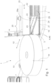
- the schematic structure of the device 1 according to the disclosure results, for example, from Figure 1 .
- the device 1 is used for machining the end region 20 of a plastic profile or plastic profile bar 2.
- the device 1 has a machine table, which is not shown.
- the support surface 10 is provided on the machine table, on which the profile 2 to be machined rests and is held for machining.
- a machining tool 11, for example a cylindrical milling cutter 13, is provided for machining.
- the bearing of the machining tool 11 and also its drive, in particular the movement drive such as the rotation drive, are not shown, but are of course provided.
- the machining tool 11 can be moved linearly at least along the double arrow 12.
- the machining tool 11 is used to machine the end area 20 of the profile bar 2.
- the end area 20 extends inwards for a few centimeters from the front end of the profile bar 2.
- the length of the end area 20 is variable and depends on the one hand on the miter angle and on the other hand on the profile thickness.
- the profile bar 2 is limited at the top and bottom by an outer profile web 22 and 21 respectively.
- the profile bar 2 rests on the support surface 10 via the lower, outer profile web 21.
- the profile bar 2 is designed, for example, as a hollow chamber profile and is also divided within the profile 2 by a plurality of profile webs 23.
- the lower, outer profile web 21 in particular was reliably held before machining by the arrangement proposed in accordance with the disclosure.
- This arrangement is characterized by a holding device 3 which is basically suitable for holding the profile bar 2, but is additionally equipped with at least one connecting element 4 which specifically interacts with the outer profile web 21 and presses it safely and reliably onto the support surface 10.
- the holding device 3 has several holding teeth 40 as connecting elements. These holding teeth 40 have an inclined holding surface 42 and are designed so that the profile web 21 can be inserted between the support surface 10 and the holding surface 42. The arrangement is selected so that the outside of the outer profile web 21 is pressed against the support surface 10 in the end region 20 and dimensional tolerances of the profile 2, especially in its end region 20, are reliably eliminated.
- the vertical position of the inner side 26 of this outer profile web 21 is determined.
- the inner distance 24 between the facing inner sides 26, 26a of the lower outer and upper outer profile webs 21 and 22 is also known.
- the vertical position of the inner side 26a of the upper outer profile web 22 is known.
- the machining tool 11 is guided at exactly the height that it just does not yet machine the inner side 26 of the lower outer profile web 21.
- the machining tool 11 has a height 14 that is the same or slightly less than Distance 24. This means that the inner side 26a of the upper outer profile web 22 is not machined.
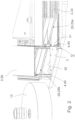
- FIG. 2 two profile bars 2, 2a, 2b are shown, which are simultaneously held by a common holding device 3.
- the holding device 3 is designed like a plate and, when viewed from above, is for example polygonal, with two long sides 31, 32 being provided in particular, which in the embodiment shown here are oriented at right angles to one another and on which the connecting elements 4, 40, here implemented as holding teeth 40, are provided.
- the two long sides 31, 32 enclose a right angle, for example; of course, the design shown here is advantageous when forming a rectangular frame, especially if these are machined at a miter angle of 45°.
- the double clamping leads to high efficiency, since two profile end areas can be machined in one processing step and the respective miter surface 29a on the first profile bar 2a and miter surface 29b on the second profile bar 2b can be produced.
- the miter surfaces 29a and 29b are formed at the same time on the respective profile bars 2a and 2b.
- the profile bars 2a and 2b are then clamped into a welding device in such a way that the two miter surfaces 29a and 29b are opposite each other and can then be welded together, as is known.
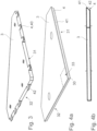
- Figure 3 shows in a first embodiment the plate-like holding device 3, which has on its two longitudinal sides 31, 32 a plurality, here four each, of connecting elements 4 designed as protruding holding teeth 40.
- the holding teeth 40 each have an inclined holding surface 42, which serve to reliably press the profile web 21 onto the support surface 10.
- the connecting element 4 is designed as a retaining edge 41, which extends over a longer area and dips in a suitable manner into the profile interior of the profile 2, above the lower outer profile web 21.
- a variant is also known in which a rectangular recess 33 (in Figure 4a indicated by dashed lines) so as to allow insertion of the respective longitudinal sides 31 and 32 into the adjacently arranged profile bars 2a, 2b.
- Figure 5d shows the application case enlarged, as it is also in Figure 1 or 2.
- the connecting element 4 is implemented as a holding tooth 40. It is equipped with an inclined holding surface 42 on its lower side facing the profile web 21.
- the height of the shoulder 43 is preferably somewhat less than the thickness of the profile web 21 in order to ensure a secure connection but also a sufficient resulting force on the support surface 10.
- a phase 28 is provided on the outer profile web 21 on its outer side of the front side, which cooperates with the inclined holding surface 42 of the connecting element 4.
- the connecting element 4 is designed as a tip 49 and in the outer profile web 21 there is a longitudinal groove 27 on its open front side, into which the tip 49 of the connecting element 4 dips.
- the lower side of the tip 49 facing the support surface 10 is in turn designed as an inclined holding surface 42 and presses the profile web 21 downwards. If necessary, the groove 27 is so wide that the upper side of the tip 49 has no or only slight contact with the profile web 21.
- Figure 5c also shows the arrangement of a tip 49 as a connecting element 4 on the holding device 3.
- the profile web 21 (similar to the embodiment according to Figure 5d ) no additional processing is carried out.
- the tip 49 is in the embodiment according to Figure 5c with sufficient force into the front material of the profile web 21 and thus leads to a holding or fixation of the profile web 21, and thus of the entire profile or profile bar 2.
Landscapes
- Engineering & Computer Science (AREA)
- Mechanical Engineering (AREA)
- Jigs For Machine Tools (AREA)
Description
- Die Erfindung betrifft ein Verfahren, gemäß dem Oberbegriff des Patentanspruchs 1, für die Bearbeitung des Endbereiches eines Kunststoffprofiles mit einer Vorrichtung für die Bearbeitung des Endbereiches eines Kunststoffprofiles, insbesondere eines Profils für die Herstellung eines Tür- oder Fensterrahmens, wobei die Vorrichtung eine Auflagefläche für das Profil und eine Halteeinrichtung für das Profil aufweist, durch welche das Profil auf der Auflagefläche gehalten ist.
- Die eingangs beschriebene Vorrichtung wird im Stand der Technik dazu verwendet, Kunststoffprofile, aus denen Tür- bzw. Fensterrahmen hergestellt werden, vor dem Verschweißvorgang herzurichten. Es geht dabei oftmals um eine exakte Positionierung und Ausrichtung der Gehrungsflächen, da diese exakte Vorbereitung das Schweißergebnis günstig mit Blick auf die Bearbeitungszeit wie auch für die resultierende Festigkeit beeinflusst.
- Als Endbereich wird hierbei der Bereich des Kunststoffprofiles angesehen, der sich vom Ende des Kunststoffprofiles ein gewisses Stück in die Profilmitte erstreckt. Die Länge des Stückes ist zum Beispiel abhängig von dem Gehrungswinkel, unter welchem die Profile zu verarbeiten sind. Üblicherweise beträgt der Endbereich wenige Zentimeter.
- Mit der eingangs beschriebenen Vorrichtung werden oftmals Kunststoff-Hohlkammerprofile bearbeitet. Es handelt sich dabei nicht um Vollmaterialprofile, die eingesetzten Hohlkammerprofile zeichnen sich durch eine bessere Isolation aus. Die einzelnen Hohlkammern werden untereinander durch längsverlaufende Profilstege abgetrennt, auch das Profil wird an seiner Außenseite durch außenliegende Profilstege begrenzt.
- Um das Profil während der Bearbeitung ausreichend zu fixieren ist vorgesehen, dass die Vorrichtung eine Auflagefläche aufweist, auf welche das Profil aufgelegt wird und auf dieser von einer Halteeinrichtung gehalten wird. Als Halteeinrichtung ist in diesem Sinne zum Beispiel ein Niederhalter oder Spanner anzusehen, ohne aber den Gegenstand dieser Erfindung hierauf beschränken zu wollen. Die (Mindest-) Aufgabe der Halteeinrichtung ist es, das Profil während der Bearbeitung in der Vorrichtung zu fixieren.
- Die
US 2008083193 A1 offenbart ein Verfahren gemäß dem Oberbegriff des Patentanspruchs 1 und beschäftigt sich diesbezüglich mit einem System zur Bearbeitung von bereits verschweißten Fensterrahmen. Dieses System umfasst eine Vorrichtung mit einer Halteeinrichtung, die mindestens ein Verbindungselement aufweist, welches mit dem äußeren Profilsteg eines Profils des Rahmens zusammenwirkt. - Aus der
CA 2922130 A1 ist ebenfalls ein System zur Verarbeitung von Fensterrahmen bekannt. Dieses Dokument offenbart eine Vorrichtung mit einer Halteeinrichtung, bei der ein Verbindungselement mit einem äußeren Profilsteg zusammenwirkt. - Die
EP 3072615 A1 lehrt einen Fräskopf, der über einen Luftzug Späne beim Fräsen von Profilen entfernt. Zudem ist auch eine Vorrichtung mit einer Halteeinrichtung offenbart, bei welcher eine Halteeinrichtung mit mindestens einem Verbindungselement auf ein Profil einwirkt. - Die
US 4102374 A offenbart eine Vorrichtung zur Herstellung von Eckelementen aus Plastikprofilen. Diese Offenlegungsschrift ist nicht direkt im Bereich der Herstellung von Fensterrahmen angesiedelt, offenbart allerdings eine Vorrichtung mit einer Halteeinrichtung für Plastikprofile. - Aus der
EP 1541878 A2 ist eine allgemein beschriebene Befestigungsvorrichtung bekannt, welche zwei Bauteile aneinander befestigt. - Die
GB 2283193 A - In der
US 5653273 A ist ein universal-präzisions-Holzbearbeitungszentrum offenbart, welches eine Gehrungslehre aufweist. - Die
WO 97/11820 A1 - Nun ist beobachtet worden, dass Kunststoffprofile, die in herkömmlichen Vorrichtungen fixiert sind, im Endbereich keine exakte Bearbeitung erlauben.
- Die Erfindung hat es sich daher zur Aufgabe gemacht, diesen Stand der Technik zu verbessern.
- Diese Aufgabe ist gelöst mit dem Verfahren gemäß Anspruch 1.
- Zur Offenbarung gehört eine Vorrichtung, wie eingangs beschrieben, wobei die Halteeinrichtung mindestens ein Verbindungselement aufweist, das mit dem äußeren Profilsteg des Profils haltend zusammenwirkt.
- Für ein ordentlich hergestellte/s Fenster oder Türe aus Kunststoffprofilen ist das bündige, versatzfreie Anschließen der Profilsichtflächen, der äußeren Profilstege, entscheidend. Maßtoleranzen und Schwindverhalten des Kunststoffmaterials sind im Stand der Technik verantwortlich für unsauber gestaltete Profilsichtflächen, gerade im Gehrungsbereich.
- Der erfindungsgemäße Vorschlag erreicht, dass die für die äußere Gestaltung wichtigen Profilstege bei der Bearbeitung exakt positioniert werden und so eine exakte Bearbeitung in Bezug auf diesen außenliegenden Profilsteg möglich ist. Bezüglich des Kunststoffprofiles typischen Maßtoleranzen oder sonstige, für die Bearbeitung negativer Materialeigenschaften, werden durch den erfindungsgemäßen Vorschlag überwunden.
- Überraschenderweise führt der erfindungsgemäße Vorschlag bei einer zerspanenden Bearbeitung des Endbereiches zu erheblich besseren Bearbeitungsergebnissen. Hierbei erfolgt eine zerspanende Bearbeitung derart, dass der äußere Profilsteg stehen bleibt. Dabei werden die in dem Profil innenliegende Profilstege, die parallel aber auch rechtwinklig bzw. schräg zum äußeren Profilsteg verlaufen, entfernt. Diese Bearbeitung führt zu einer Destabilisierung des äußeren Profilsteges, dem die Fixierung durch den erfindungsgemäßen Vorschlag gerade entgegenwirkt und so gerade während der Bearbeitung diesen äußeren Profilsteg stützt und festhält.
- Gerade bei solchen Bearbeitungen ist der erfindungsgemäße Vorschlag günstig und vermeidet Ausschussproduktion.
- Gleichwirkend mit einer Auflagefläche ist es auch, wenn das Profil von zwei zusammenwirkenden Spannbacken, gegebenenfalls auch ohne auf einer Auflagefläche aufzuliegen, gehalten wird.
- Des Weiteren ist in dem Vorschlag in offenbarungsgemäßer Weise vorgesehen, dass die Halteeinrichtung auf oder in der Auflagefläche angeordnet ist. Die Halteeinrichtung unterstützt somit auch die Funktion der Auflagefläche, denn die Halteeinrichtung fixiert das Profil auf der Auflagefläche. Es ist dabei klar, dass die Erfindung auch den Einsatz mehrerer, gegebenenfalls auch unterschiedlich wirkender Halteeinrichtungen umfasst, wobei zum Beispiel die Halteeinrichtung, welche mit einem Verbindungselement ausgestattet ist, mit einer als Spanner oder Niederhalter ausgeführten Halteeinrichtung zusammenwirkt.
- Bei einer bevorzugten Ausgestaltung des Vorschlags ist vorgesehen, dass die Halteeinrichtung plattenartig ausgebildet ist. Eine plattenartige Ausgestaltung zeichnet sich dadurch aus, dass die, in Draufsicht gesehene Deckfläche, verhältnismäßig groß ist und die Halteeinrichtung eine verhältnismäßig geringe Dicke aufweist. Dabei wird die Deckfläche von mehreren Seitenkanten begrenzt, an denen die Verbindungselemente vorgesehen sind. Die plattenartige Ausgestaltung kombiniert damit geschickt eine schmalbauende Konstruktion mit einer hohen Stabilität, da an den Seitenkanten eine Vielzahl einzelner Verbindungselemente bzw. ein Verbindungselement an einer langen Strecke angeordnet werden könnte. Damit wird der außenliegende Profilsteg entlang einer möglichst langen Strecke gehalten, was zu einer hohen Prozess-sicherheit führt.
- Des Weiteren ist vorgesehen, dass die Halteeinrichtung zwei Längsseiten aufweist, die Längsseiten je mindestens ein Verbindungselement trägt und die Längsseiten zueinander einen Winkel, bevorzugt einen rechten Winkel, einschließen, der den Innenwinkel des herzustellenden Tür- oder Fensterrahmens entspricht. Die Anordnung wird geschickter Weise so gewählt, dass mit einem Aufspannprozess gleich zwei oder jedenfalls noch mehr Profile von der Halteeinrichtung gehalten werden. Da auf den Aufspannprozess dann eine zerspanende Bearbeitung erfolgt, ist es geschickt, die Anordnung gleich so zu wählen, dass mit einem zerspanenden Bearbeitungsschritt zumindest zwei oder noch mehr Profile gleichzeitig bearbeitet werden können. Der Vorschlag unterstützt somit eine effektive, kostensparende Bearbeitung.
- In einer vorteilhaften Ausgestaltung ist vorgesehen, dass das Verbindungselement den Profilsteg durch Formschluss und/oder Kraftschluss hält.
- Für die Ausgestaltung des Verbindungselementes werden mehrere Alternativen vorgesehen. Zunächst ist vorgesehen, dass das Verbindungselement, als an der Halteeinrichtung vorstehender Haltezahn, ausgebildet ist. Nach diesem Vorschlag wird das Verbindungselement bereits aus einem Haltezahn gebildet. Natürlich umfasst der Vorschlag auch Varianten mit mehr als einen Haltezahn, zum Beispiel zwei, drei, vier oder noch mehr Haltezähnen.
- Alternativ ist vorgesehen, dass das Verbindungselement als Haltekante ausgebildet ist. Dabei erstreckt sich die Haltekante geschickterweise über einen größeren Bereich der Längsseite und greift über einen größeren Bereich an dem Profilsteg ein.
- Die beiden vorbeschriebenen Varianten sind bevorzugte Beispiele für die Realisierung eines formschlüssigen Verbundes zwischen dem Verbindungselement und dem Profilsteg. Dabei wird der Profilsteg unter den vorstehenden Haltezahn bzw. Haltekante geschoben und so festgehalten. Sie können aber auch in einem kraftschlüssigen Konzept eingesetzt sein.
- Dabei ist offenbarungsgemäß vorgesehen, dass die Halteeinrichtung zusammen mit dem Verbindungselement bevorzugt in einer Relativbewegung parallel zur Längserstreckung des Profils gegen die Stirnseite des Profils bewegt wird. Dies umfasst die Lösung, dass das Profil gegen die Halteeinrichtung angestellt wird oder die Halteeinrichtung gegen das Profil bewegt wird, sowie auch eine kombinierte Bewegung.
- Bei der vorgeschlagenen Variante eines kraftschlüssigen Verbundes wird die dem Profil zugewandte Frontseite oder Spitze des Verbindungselementes mit Kraft gegen das Profil gedrückt/bewegt. Der offenbarungsgemäße Vorschlag umfasst aber auch eine Lösung, bei welchen sich im Profilsteg eine Nut, Auskerbung, Ausnehmung oder Loch befindet, in die das Verbindungselement haltend eingreift.
- Geschickter Weise ist vorgesehen, dass das Verbindungselement eine schräg gestellte Haltefläche aufweist. Diese schräg gestellte Haltefläche ist sowohl bei der Variante Haltezahn wie auch bei der Variante Haltekante realisierbar. Die Orientierung der Haltefläche ist dabei so gewählt, dass bei Einschieben des Verbindungselementes in den Profilsteg mit zunehmenden Einschubweg, der Profilsteg zunehmend nach unten, auf die Auflagefläche, gedrückt wird. Es erfolgt so eine zuverlässige, insbesondere vertikale Festlegung des Profilsteges.
- In einer weiteren bevorzugten Ausführungsform ist vorgesehen, dass die Vorrichtung mindestens ein, zumindest entlang der Raumrichtung, bewegbares Bearbeitungswerkzeug aufweist, und die Halteeinrichtung an dem Bearbeitungswerkzeug angeordnet ist. Als Bearbeitungswerkzeug ist zum Beispiel ein spanabhebendes Bearbeitungswerkzeug (zum Beispiel ein Walzenfräser) vorgesehen, ohne aber die Erfindung hierauf festlegen zu wollen. Das Bearbeitungswerkzeug ist für eine Bearbeitung des Endbereiches vorgesehen. Es wurde bereits drauf hingewiesen, dass die offenbarungsgemäße Vorrichtung, auch unterschiedlich wirkende Halteeinrichtungen aufweist und zum Beispiel eine erste Halteeinrichtung den Profilstab - oder das Profil - auf die Auflagefläche spannt und eine zweite Halteeinrichtung, die an dem Bearbeitungswerkzeug angeordnet ist, bei Einsatz des Bearbeitungswerkzeuge (bevorzugt kurz zuvor) mit dem äußeren Profilsteg in Wirkkontakt tritt und so den äußeren Profilsteg kurz vor der Bearbeitung zuverlässig festlegt. Natürlich umfasst die Offenbarung auch eine Lösung, die mit nur einer solchen am Bearbeitungswerkzeug angeordneten Halteeinrichtung ausgestattet ist.
- Des Weiteren ist günstiger Weise vorgesehen, dass die Vorrichtung zumindest eine Spannvorrichtung aufweist, und die Spannvorrichtung das Profil auf die Auflagefläche drückt und an der Spannvorrichtung die Halteeinrichtung vorgesehen ist. Der Vorschlag beschränkt sich nicht darauf, dass nur der Profilsteg, der auf der Auflagefläche aufliegt, während der Bearbeitung durch die Halteeinrichtung sicher positioniert ist. Die Offenbarung hat erkannt, dass der Vorschlag insgesamt die Bearbeitung verbessert und Ausschuss vermeidet, wenn auch noch andere, außenliegende Profilstege während der Bearbeitung in geeigneter Weise gehalten werden. Daher umfasst die Offenbarung auch Vorschläge, bei welchen die Profilstege festgehalten werden, die nicht unmittelbar auf der Auflagefläche aufliegen. Eine solche Variante wird mit dem vorgenannten Merkmal vorgeschlagen, bei welchen an der Spannvorrichtung (als erste Halteeinrichtung) eine (zweite) Halteeinrichtung (im Sinne der Erfindung), mit einer, mit dem äußeren Profilsteg zusammenwirkenden Verbindungselement, ausgestattet ist.
- Üblicherweise liegt das Profil (hierzu gleichbedeutend Profilstab) auf der Auflagefläche auf und wird von der Spannvorrichtung bevorzugt vertikal von oben nach unten auf die Auflagefläche gespannt. Die verschiedenen Varianten der Offenbarung ermöglichen es jetzt, dass sowohl der äußere Profilsteg, der auf der Auflagefläche aufliegt wie auch der Profilstab, der auf der, der Auflagefläche abgewandten Seite zugeordnet ist, wie auch die seitlichen Profilstege, je nach Anwendungsfall, während der Bearbeitung, zuverlässig gehalten werden.
- Dabei ist zu beachten, dass an einer Vorrichtung eine oder auch mehrere Halteeinrichtungen vorgesehen sein können, die je ein äußeren Profilsteg halten. Der geschickten Anordnung ist es also möglich, zum Beispiel zwei oder noch mehr äußere Profilstege so festzulegen, dass eine zuverlässige Bearbeitung möglich ist.
- Der Vorschlag gemäß der Erfindung ist ausgesprochen variabel realisierbar. Zunächst ist vorgesehen, dass die Halteeinrichtung mit dem vorgeschlagenen Verbindungselement in der Auflagefläche angeordnet, also zum Beispiel in dieser integriert ausgebildet ist. Alternativ ist es möglich, dass diese Halteeinrichtung zum Beispiel an dem beweglich gelagerten Bearbeitungswerkzeug oder der Spanneinrichtung angeordnet ist. Dabei umfasst der Vorschlag aber auch Lösungen, bei welchen diese Halteeinrichtung mit Verbindungselement separat an das Profil bzw. den Profilstab angestellt werden kann, also hierfür separate Antriebe zur Verfügung stehen. Dies kann zum Beispiel bei komplexen Profilen oder aber auch bei rechtwinklig zur Auflagefläche verlaufenden äußeren Profilstegen von Vorteil sein.
- Die eingangs beschriebene Aufgabe wird durch ein System wie nachfolgend beschrieben gelöst. Die Offenbarung umfasst daher auch ein System für die Bearbeitung des Endbereiches eines Kunststoffprofiles, insbesondere eines Profils für die Herstellung eines Tür- oder Fensterrahmens, wobei das System eine Vorrichtung, wie vorbeschrieben, sowie ein Kunststoffprofil aufweist, das von der Vorrichtung bearbeitet wird, und die Halteeinrichtung mindestens ein Verbindungselement aufweist, das mit dem äußeren Profilsteg des Profils haltend zusammenwirkt. Die Vorzüge des offenbarungsgemäßen Vorschlages treten gerade bei dem effektiven Zusammenwirken mit dem Profil zutage.
- Bei einer bevorzugten Ausgestaltung des Vorschlags ist vorgesehen, dass das System für die Bearbeitung zweier winklig, bevorzugt rechtwinklig zueinander orientierter Profilstäbe vorgesehen ist, und das Bearbeitungswerkzeug zum Beispiel ein Walzenfräser ist, dessen Höhe gleich oder geringfügig geringer ist, als der Innenabstand der einander gegenüberstehenden Profilstege. Der offenbarungsgemäße Vorschlag erreicht in eleganter Weise, dass eine hochexakte und sichere Bearbeitung des Volumens zwischen zwei gegenüberliegenden äußeren Profilstegen möglich ist. Mindestens ein äußerer Profilsteg, ist durch den offenbarungsgemäßen Vorschlag in seiner Höhenlage exakt festgelegt und mit einem Bearbeitungsschritt kann der Innenraum entsprechend entfernt werden.
- Die Offenbarung schlägt bevorzugt einen Walzenfräser als Bearbeitungswerkzeug vor, ohne aber die Offenbarung hierauf zu beschränken. Der Pfiff dieses Vorschlages liegt darin, dass die Bearbeitungshöhe des eingesetzten Bearbeitungswerkzeuges exakt geplant werden kann, da die Höhenlage bzw. Abstand der Innenflächen der jeweilig äußeren Profilstege genau bestimmt und festgelegt und als Maschinenparameter bekannt ist.
- Die Erfindung ist in Anspruch 1 definiert und betrifft ein Verfahren für die Bearbeitung des Endbereiches eines Kunststoffprofiles, insbesondere eines Profils für die Herstellung eines Tür- oder Fensterrahmens. Bei diesem erfindungsgemäßen Verfahren wird die vorbeschriebene Vorrichtung eingesetzt. Das erfindungsgemäße Verfahren zeichnet sich durch die Abfolge folgender Schritte aus:
- Auflegen eines zu bearbeitenden Kunststoffprofiles auf einer Auflagefläche
- relatives Anstellen der Halteeinrichtung gegen den offenen Stirnbereich des Profils derart, dass das Verbindungselement der Halteeinrichtung in haltenden Eingriff mit dem äußeren Profilsteg gelangt.
- Des Weiteren ist in dem Vorschlag vorteilhafter Weise vorgesehen, dass nach dem haltenden Eingreifen des Verbindungselements am äußeren Profilsteg ein Entfernen von Material oder Bearbeitung im Endbereich des Profilstabes erfolgt, bei welchen insbesondere der äußere Profilsteg nicht entfernt wird. Diese Bearbeitung erfolgt bevorzugt mit einem zerspannenden Bearbeitungswerkzeug.
- Des Weiteren umfasst die Offenbarung auch die Verwendung einer vorbeschriebenen Vorrichtung für die Befestigung und gegebenenfalls anschließende Bearbeitung, mindestens eines Kunststoff-profiles als Teil eines Tür- oder Fensterrahmens.
- Üblicherweise werden Kunststofffensterrähmen auf Gehrung geschnitten verschweißt. Das bedeutet, dass die Profilstabenden vollständig unter einem Gehrungswinkel geschnitten werden und dann mit dem anderen winklig anschließenden Profil bzw. Profilstab verschweißt wird. Am fertigen Fensterrahmen erkennt man dann die Gehrungsfläche, die in der Regel den halben Innenwinkel der Fensterecke beschreibt. Das Verschweißen der Kunststoffprofile unter dem Gehrungswinkel führt auch zu einer verhältnismäßig großen Schweißfläche und somit zu hohen Eckfestigkeiten. Die Erfindung erlaubt es nun mit hoher Effizienz, Genauigkeit und Eckfestigkeit Kunststoffprofile miteinander zu verschweißen, die eine klassische Verbindungstechnik in Ansicht zeigen, da die Profilstäbe sichtbar rechtwinklig im Eckbereich anschließen, aber tatsächlich die Profilstäbe doch unter einem Gehrungswinkel, verdeckt, durch die äußere Profilstege, miteinander verschweißt sind.
- Es ist natürlich klar, dass der am ersten Profilstab verbleibende, überstehende äußere Profilsteg einen inneren Bereich des zweiten winkelig anschließenden Profilstabes überdeckt, d.h. an diesem zweiten Profilstab wurde eben der äußere Profilsteg abgenommen und der innere Bereich freigelegt.
- In der Zeichnung ist die Offenbarung insbesondere in einem Ausführungsbeispiel schematisch dargestellt. Es zeigen:
- Fig. 1, 2
- je in einer dreidimensionalen Ansicht, verschiedene Ausführungsbeispiele einer offenbarungsgemäßen Vorrichtung
- Fig. 3
- in einer dreidimensionalen Ansicht, eine erste Variante einer Halteeinrichtung nach der Offenbarung
- Fig. 4a
- in einer dreidimensionalen Ansicht, eine zweite Variante einer Halteeinrichtung nach der Offenbarung
- Fig. 4b
- eine Seitenansicht nach
Figur 4a - Fig. 5a, 5b, 5c, 5d
- je in einer Seitenansicht, Details (aus dem Ausschnitt V aus
Figur 2 ) verschiedener Ausführungsbeispiele über das Zusammenwirken des Verbindungselementes mit dem Profilsteg nach der Offenbarung - In den Figuren sind gleiche oder einander entsprechende Elemente jeweils mit den gleichen Bezugszeichen bezeichnet und werden daher, sofern nicht zweckmäßig, nicht erneut beschrieben. Die in der gesamten Beschreibung enthaltenen Offenbarungen sind sinngemäß auf gleiche Teile mit gleichen Bezugszeichen bzw. gleichen Bauteilbezeichnungen übertragbar. Auch sind die in der Beschreibung gewählten Lageangaben, wie z.B. oben, unten, seitlich usw. auf die unmittelbar beschriebene sowie dargestellte Figur bezogen und sind bei einer Lageänderung sinngemäß auf die neue Lage zu übertragen.
- Der schematische Aufbau der Vorrichtung 1 nach der Offenbarung ergibt sich zum Beispiel aus
Figur 1 . Die Vorrichtung 1 dient für die Bearbeitung des Endbereiches 20 eines Kunststoffprofiles oder Kunststoffprofilstabes 2. Die Vorrichtung 1 besitzt dabei einen Maschinentisch, der nicht gezeigt ist. An dem Maschinentisch ist die Auflagefläche 10 vorgesehen, auf dem das zu bearbeitende Profil 2 aufliegt und für eine Bearbeitung gehalten ist. - Für die Bearbeitung ist ein Bearbeitungswerkzeug 11, zum Beispiel ein Walzenfräser 13 vorgesehen. Auch hier ist zur Erhöhung der Übersichtlichkeit die Lagerung des Bearbeitungswerkzeuges 11 und auch sein Antrieb, insbesondere der Bewegungsantrieb wie der Rotationsantrieb nicht gezeigt, aber natürlich vorgesehen. Das Bearbeitungswerkzeug 11 ist zumindest entlang des Doppelpfeils 12 linear bewegbar.
- Das Bearbeitungswerkzeug 11 dient zur Bearbeitung des Endbereiches 20 des Profilstabes 2. Der Endbereich 20 erstreckt sich dabei über einige Zentimeter von dem stirnseitigen Ende des Profilstabes 2 nach innen. Die Länge des Endbereiches 20 ist variabel und hängt einerseits von dem Gehrungswinkel und andererseits von dem Profildicken ab. Der Profilstab 2 wird oben und unten je von einem äußeren Profilsteg 22 bzw. 21 begrenzt. Dabei liegt der Profilstab 2 über den unteren, äußeren Profilsteg 21 auf der Auflagefläche 10 auf. Der Profilstab 2 ist zum Beispiel als Hohlkammerprofil ausgebildet und wird auch innerhalb des Profils 2 von einer Vielzahl von Profilstegen 23 unterteilt.
- In
Figur 1 ist die Situation nach Durchführung der Bearbeitung gezeigt, insbesondere von dem oberen äußeren Profilsteg 22 verdeckt wurde im Innenbereich des Profils 2 eine, bezogen auf die Längserstreckung 25 des Profils schrägstehende Gehrungsfläche 29 erzeugt, die außenseitig jeweils durch die vorstehenden Profilstege 21 und 22 begrenzt ist. - Um die hier gezeigte exakte Bearbeitung ausführen zu können wurde insbesondere der untere, äußere Profilsteg 21 vor der Bearbeitung durch die offenbarungsgemäße vorgeschlagene Anordnung zuverlässig gehalten. Diese Anordnung zeichnet sich durch eine Halteeinrichtung 3 aus, die grundsätzlich dazu geeignet ist, den Profilstab 2 zu halten, aber zusätzlich mit mindestens einem Verbindungselement 4 ausgestattet ist, das speziell mit dem äußeren Profilsteg 21 zusammenwirkt und diesen sicher und zuverlässig auf die Auflagefläche 10 drückt.
- In dem hier gezeigten Ausführungsbeispiel trägt die Halteeinrichtung 3 mehrere Haltezähne 40 als Verbindungselemente. Diese Haltezähne 40 besitzen eine schräg stehende Haltefläche 42 und sind so gestaltet, dass der Profilsteg 21 zwischen der Auflagefläche 10 und der Haltefläche 42 eingeschoben werden kann. Die Anordnung ist dabei so gewählt, dass die Außenseite des äußeren Profilsteges 21 gerade im Endbereich 20 gegen die Auflagefläche 10 gedrückt wird und so Maßtoleranzen des Profils 2, gerade in seinem Endbereich 20, sicher eliminiert werden.
- Durch das exakte Festhalten des Endbereiches 20 des äußeren Profilsteges 21 ist die vertikal Lage der Innenseite 26 dieses äußeren Profilsteges 21 festgelegt. Auch ist der innere Abstand 24 zwischen den einander zugewandten Innenseiten 26, 26a des unteren äußeren und oberen äußeren Profilsteges 21 und 22 bekannt. Damit ist dann auch die vertikale Position der Innenseite 26a des oberen äußeren Profilsteges 22 bekannt. Nun wird das Bearbeitungswerkzeug 11 in genau der Höhe geführt, dass es gerade noch nicht die Innenseite 26 des unteren äußeren Profilsteges 21 bearbeitet. Geschickterweise besitzt das Bearbeitungswerkzeug 11 eine Höhe 14, die gleich oder geringfügig geringer ist wieder in Abstand 24. Damit wird auch gerade die Innenseite 26a des oberen äußeren Profilsteges 22 nicht bearbeitet.
- Es ist klar, dass bei Profilstäben mit großen Maßtoleranzen natürlich auch der obere Profilsteg 22 mit einer Halteeinrichtung 3, wie sie beschrieben wurde und in der Auflagefläche 10 integriert ist, gehalten werden kann und so auch solche ungenauen Profile zuverlässig verarbeitet werden können.
- In
Figur 1 ist die Bearbeitung nur eines aufgespannten Profilstabes 2 gezeigt. - In
Figur 2 sind zwei Profilstäbe 2, 2a, 2b gezeigt, die gleichzeitig durch eine gemeinsame Halteeinrichtung 3 gehalten sind. Hierzu ist die Halteeinrichtung 3 plattenartig ausgestaltet und in Draufsicht gesehen zum Beispiel mehreckig gebildet, wobei insbesondere zwei Längsseiten 31, 32 vorgesehen sind, die in dem hier gezeigten Ausführungsbeispiel rechtwinkelig zueinander orientiert sind und an denen die Verbindungselemente 4,40, hier als Haltezähne 40 realisiert, vorgesehen sind. Die beiden Längsseiten 31,32 schließen dabei zum Beispiel einen rechten Winkel ein, natürlich ist die hier gezeigte Ausgestaltung bei Bildung eines rechtwinkligen Rahmens günstig, insbesondere wenn diese unter einem Gehrungswinkel von 45° bearbeitet werden. Die zweifache Aufspannung führt zu einer hohen Effizienz, da mit einem Bearbeitungsschritt gleich zwei Profilendbereiche bearbeitet und so die jeweiligen Gehrungsfläche 29a an dem ersten Profilstab 2a und Gehrungsfläche 29b an dem zweiten Profilstab 2b hergestellt werden können. - Es werden somit gleichzeitig die Gehrungsflächen 29a und 29b an den jeweiligen Profilstäben 2a bzw. 2b gestaltet. In der in
Figur 2 gezeigten Anordnung erfolgt dann, ein Umspannen der Profilstäbe 2a und 2b in eine Schweißvorrichtung, derart, dass die beiden Gehrungsflächen 29a und 29b einander gegenüberliegend sind und dann, wie bekannt, miteinander verschweißt werden können. -
Figur 3 zeigt in einem ersten Ausführungsbeispiel die plattenartige Halteeinrichtung 3, die an ihren beiden Längsseiten 31,32 eine Mehrzahl, hier jeweils vier, als vorstehende Haltezähne 40 ausgebildete Verbindungselemente 4 aufweist. Die Haltezähne 40 besitzen je eine schräg stehende Haltefläche 42, die dazu dienen, den Profilsteg 21 zuverlässig auf die Auflagefläche 10 zu drücken. - In
Figur 4a und 4b ist anstelle eines Haltezahnes 40 das Verbindungselement 4 als Haltekante 41 ausgebildet, die sich über einen längeren Bereich erstreckt und in geeigneter Weise in das Profilinnere des Profils 2, oberhalb des unteren äußeren Profilsteges 21 eintaucht. - Es ist auch eine Variante bekannt, bei welchen an der Außenecke 30 eine rechteckige Ausnehmung 33 (in
Figur 4a gestrichelt angedeutet) angeordnet ist, um so ein Einführen der jeweiligen Längsseiten 31 und 32 in die benachbart angeordneten Profilstäbe 2a, 2b zu erlauben. - Bei den
Figuren 5a bis 5d sind verschiedene Varianten über das Zusammenwirken des Verbindungselementes 4 mit dem Profilsteg 21 gezeigt. All die hier gezeigten Beispiele zeigen das vorteilhafte systemhafte Zusammenwirken der vorgeschlagenen Vorrichtung 1 mit dem hiermit gehaltenen Profil 2. -
Figur 5d zeigt vergrößert den Anwendungsfall, wie er auch inFigur 1 bzw. 2 gezeigt ist. In dem hier gezeigten Ausführungsbeispiel ist das Verbindungselement 4 als Haltezahn 40 realisiert. Er ist auf seiner unteren, dem Profilsteg 21 zugewandten Seite mit einer schräg stehenden Haltefläche 42 ausgestattet. Die Höhe des Absatzes 43 ist dabei bevorzugter Weise etwas geringer wie die Dicke des Profilsteges 21, um eine sichere Verbindung aber auch eine ausreichende resultierende Kraft auf die Auflagefläche 10 zu bewirken. - In
Figur 5a ist an dem äußeren Profilsteg 21 an seiner Außenseite der Stirnseite eine Phase 28 vorgesehen, die mit der schräg stehenden Haltefläche 42 des Verbindungselementes 4 zusammenwirkt. - In
Figur 5b ist das Verbindungselement 4 als Spitze 49 ausgebildet und in dem äußeren Profilsteg 21 befindet sich an dessen offener Stirnseite eine längsverlaufende Nut 27, in die die Spitze 49 des Verbindungselementes 4 eintaucht. Die untere, der Auflagefläche 10 zugewandte Seite der Spitze 49 ist wiederum als schräg stehende Haltefläche 42 ausgebildet und drückt den Profilsteg 21 nach unten. Gegebenenfalls ist die Nut 27 so breit, dass die obere Seite der Spitze 49 keinen oder nur geringen Kontakt mit dem Profilsteg 21 hat. -
Figur 5c zeigt auch die Anordnung einer Spitze 49 als Verbindungselement 4 an der Halteeinrichtung 3. In diesem Fall wird aber an dem Profilsteg 21 (ähnlich wie in dem Ausführungsbeispiel nachFigur 5d ) keine zusätzliche Bearbeitung vorgenommen. Die Spitze 49 wird in dem Ausführungsbeispiel nachFigur 5c mit ausreichender Kraft in das stirnseitige Material des Profilsteges 21 gedrückt und führt so zu einem Festhalten bzw. einer Fixierung des Profilsteges 21, und somit des gesamten Profils bzw. Profilstabes 2. - Es ist klar, dass die in den
Figuren 5a bis 5d gezeigten Varianten die Ausgestaltung des Verbindungselementes 4 nicht entweder auf einen Haltezahn 40 oder auf eine Haltekante 41 festlegen, die gezeigten Ausführungsbeispiele können wahlweise für beide Formen des Verbindungselementes 4 genutzt werden.
Claims (2)
- Verfahren für die Bearbeitung des Endbereiches eines Kunststoffprofiles, insbesondere eines Profils für die Herstellung eines Tür- oder Fensterrahmens, mit einer Vorrichtung (1) für die Bearbeitung des Endbereiches (20) eines Kunststoffprofiles (2), insbesondere eines Profils für die Herstellung eines Tür- oder Fensterrahmens, wobei die Vorrichtung (1) eine Auflagefläche (10) für das Profil (2) und eine Halteeinrichtung (3) für das Profil (2) aufweist, durch welche das Profil (2) auf der Auflagefläche (10) gehalten ist, wobei die Halteeinrichtung (3) mindestens ein Verbindungselement (4) aufweist, das mit einem äußeren Profilsteg (21, 22) des Profils (2) haltend zusammenwirkt, gekennzeichnet durch die Abfolge folgender Schritte:- Auflegen eines zu bearbeitenden Kunststoffprofiles auf einer Auflagefläche (10)- relatives Anstellen der Halteeinrichtung (3) gegen den offenen Stirnbereich des Profils (2) derart, dass das Verbindungselement (4) der Halteeinrichtung (3) in haltenden Eingriff mit dem äußeren Profilsteg (21, 22) gelangt.
- Verfahren nach Anspruch 1, dadurch gekennzeichnet, dass nach dem haltenden Eingreifen des Verbindungselements (4) am äußeren Profilsteg (21, 22) ein Entfernen von Material oder Bearbeitung im Endbereich des Profilstabes erfolgt, bei welchen insbesondere der äußere Profilsteg (21, 22) nicht entfernt wird.
Applications Claiming Priority (1)
| Application Number | Priority Date | Filing Date | Title |
|---|---|---|---|
| DE102017126492.2A DE102017126492A1 (de) | 2017-11-10 | 2017-11-10 | Vorrichtung für die Profilbearbeitung |
Publications (3)
| Publication Number | Publication Date |
|---|---|
| EP3482857A1 EP3482857A1 (de) | 2019-05-15 |
| EP3482857C0 EP3482857C0 (de) | 2024-11-06 |
| EP3482857B1 true EP3482857B1 (de) | 2024-11-06 |
Family
ID=64184023
Family Applications (1)
| Application Number | Title | Priority Date | Filing Date |
|---|---|---|---|
| EP18205045.0A Active EP3482857B1 (de) | 2017-11-10 | 2018-11-07 | Vorrichtung und verfahren für die profilbearbeitung |
Country Status (4)
| Country | Link |
|---|---|
| EP (1) | EP3482857B1 (de) |
| DE (1) | DE102017126492A1 (de) |
| ES (1) | ES3002692T3 (de) |
| PL (1) | PL3482857T3 (de) |
Citations (2)
| Publication number | Priority date | Publication date | Assignee | Title |
|---|---|---|---|---|
| WO1997011820A1 (en) * | 1995-09-25 | 1997-04-03 | Frank Michael John Kent | Multi-functional worktable systems |
| US5653273A (en) * | 1995-08-14 | 1997-08-05 | Bach; Emin Nelson | Universal precision woodworking center |
Family Cites Families (6)
| Publication number | Priority date | Publication date | Assignee | Title |
|---|---|---|---|---|
| US4102374A (en) * | 1976-03-08 | 1978-07-25 | Fred Godfrey Klein | Jig and template apparatus and method for preparing a corner insert for a laminated plastic countertop |
| GB2283193A (en) * | 1993-09-24 | 1995-05-03 | Jade Engineering | Profile trimming apparatus |
| DE10357844B4 (de) * | 2003-12-11 | 2006-02-23 | Hilti Ag | Befestigungssystem |
| US7921064B2 (en) * | 2006-10-10 | 2011-04-05 | Ged Integrated Solutions, Inc. | System and method for cleaning window frames after learning their unknown profile using non-contact sensors |
| HUE057972T2 (hu) * | 2013-08-29 | 2022-06-28 | Ged Integrated Solutions Inc | Ablak tisztító rendszer és eljárás |
| DE202015101493U1 (de) * | 2015-03-24 | 2016-06-28 | Urban Gmbh & Co Maschinenbau Kg | Fräser |
-
2017
- 2017-11-10 DE DE102017126492.2A patent/DE102017126492A1/de active Pending
-
2018
- 2018-11-07 EP EP18205045.0A patent/EP3482857B1/de active Active
- 2018-11-07 PL PL18205045.0T patent/PL3482857T3/pl unknown
- 2018-11-07 ES ES18205045T patent/ES3002692T3/es active Active
Patent Citations (2)
| Publication number | Priority date | Publication date | Assignee | Title |
|---|---|---|---|---|
| US5653273A (en) * | 1995-08-14 | 1997-08-05 | Bach; Emin Nelson | Universal precision woodworking center |
| WO1997011820A1 (en) * | 1995-09-25 | 1997-04-03 | Frank Michael John Kent | Multi-functional worktable systems |
Also Published As
| Publication number | Publication date |
|---|---|
| EP3482857A1 (de) | 2019-05-15 |
| ES3002692T3 (en) | 2025-03-07 |
| EP3482857C0 (de) | 2024-11-06 |
| DE102017126492A1 (de) | 2019-05-16 |
| PL3482857T3 (pl) | 2025-02-24 |
Similar Documents
| Publication | Publication Date | Title |
|---|---|---|
| EP2651580B1 (de) | Verfahren zum fräsen einer ausnehmung in einem werkstück und werkstück mit einer ausnehmung | |
| EP3031547B1 (de) | Verfahren und vorrichtung zum herstellen einer eckverbindung | |
| EP0254741B1 (de) | Vorrichtung zur halterung und handhabung eines flachen gegenstandes | |
| DE2741388A1 (de) | Stirnmesserkopf zum verzahnen von zahnraedern | |
| AT391645B (de) | Lehrenvorrichtung fuer moebelteile | |
| EP1894654B1 (de) | Verfahren und Bearbeitungseinheit zum Bearbeiten der Eckverbindungen von aus Profilstücken geschweissten Rahmen | |
| DE4326387C2 (de) | Maschinengestell und Verfahren zu dessen Herstellung | |
| DE69012313T2 (de) | Numerisch gesteuerte maschine zum bearbeiten oder messen mit einer befestigungsvorrichtung für ein werkstück auf einem werktisch. | |
| EP3482857B1 (de) | Vorrichtung und verfahren für die profilbearbeitung | |
| EP1215002B1 (de) | Vorrichtung zum Bearbeiten von Eckverbindungen | |
| DE2526857A1 (de) | Rahmenpresse zur schaffung von eckverbindungen an fenster- und tuerrahmen | |
| EP0263476A2 (de) | Verfahren zum Ausrichten einer Formplatte auf einem Werkzeugmaschinentisch und Ausrichtsegment zur Durchführung des Verfahrens | |
| EP0796720B1 (de) | Verfahren zur Herstellung von Rahmen | |
| EP0873815A2 (de) | Werkstückspannung über Einzugsnippel | |
| EP1813824A2 (de) | Verbindungsvorrichtung für Möbelplatten | |
| DE4320274A1 (de) | Verstellbarer Spannrahmen zum Spannen eines Maler-Laminats | |
| DE102011102793B3 (de) | Verfahren zur Bearbeitung der Stirnseiten von Werkstücken aus Holz, Kunststoff und dergleichen | |
| WO2017134696A1 (de) | Schafträser | |
| AT410289B (de) | Verfahren und vorrichtung zur bildung einer dreiseitig begrenzten ecke aus einem ebenflächigen, plattenförmigen material | |
| DE2437288C3 (de) | Schneidwerkzeug für die spanabhebende Bearbeitung | |
| EP2012955B1 (de) | Spannkopf | |
| EP3925746A1 (de) | Verfahren und vorrichtung zum bearbeiten eines endbereichs eines profils | |
| CH688366A5 (de) | Stanzwerkzeug fuer Blechteile. | |
| EP0990476A2 (de) | Wendeschneidplatte | |
| DE3540656A1 (de) | Maschine zum herstellen einer eckverbindung fuer werkstuecke aus holz |
Legal Events
| Date | Code | Title | Description |
|---|---|---|---|
| PUAI | Public reference made under article 153(3) epc to a published international application that has entered the european phase |
Free format text: ORIGINAL CODE: 0009012 |
|
| STAA | Information on the status of an ep patent application or granted ep patent |
Free format text: STATUS: THE APPLICATION HAS BEEN PUBLISHED |
|
| AK | Designated contracting states |
Kind code of ref document: A1 Designated state(s): AL AT BE BG CH CY CZ DE DK EE ES FI FR GB GR HR HU IE IS IT LI LT LU LV MC MK MT NL NO PL PT RO RS SE SI SK SM TR |
|
| AX | Request for extension of the european patent |
Extension state: BA ME |
|
| STAA | Information on the status of an ep patent application or granted ep patent |
Free format text: STATUS: REQUEST FOR EXAMINATION WAS MADE |
|
| 17P | Request for examination filed |
Effective date: 20191115 |
|
| RBV | Designated contracting states (corrected) |
Designated state(s): AL AT BE BG CH CY CZ DE DK EE ES FI FR GB GR HR HU IE IS IT LI LT LU LV MC MK MT NL NO PL PT RO RS SE SI SK SM TR |
|
| STAA | Information on the status of an ep patent application or granted ep patent |
Free format text: STATUS: EXAMINATION IS IN PROGRESS |
|
| 17Q | First examination report despatched |
Effective date: 20200803 |
|
| GRAP | Despatch of communication of intention to grant a patent |
Free format text: ORIGINAL CODE: EPIDOSNIGR1 |
|
| STAA | Information on the status of an ep patent application or granted ep patent |
Free format text: STATUS: GRANT OF PATENT IS INTENDED |
|
| INTG | Intention to grant announced |
Effective date: 20240531 |
|
| GRAS | Grant fee paid |
Free format text: ORIGINAL CODE: EPIDOSNIGR3 |
|
| GRAA | (expected) grant |
Free format text: ORIGINAL CODE: 0009210 |
|
| STAA | Information on the status of an ep patent application or granted ep patent |
Free format text: STATUS: THE PATENT HAS BEEN GRANTED |
|
| AK | Designated contracting states |
Kind code of ref document: B1 Designated state(s): AL AT BE BG CH CY CZ DE DK EE ES FI FR GB GR HR HU IE IS IT LI LT LU LV MC MK MT NL NO PL PT RO RS SE SI SK SM TR |
|
| REG | Reference to a national code |
Ref country code: GB Ref legal event code: FG4D Free format text: NOT ENGLISH |
|
| REG | Reference to a national code |
Ref country code: CH Ref legal event code: EP |
|
| REG | Reference to a national code |
Ref country code: DE Ref legal event code: R096 Ref document number: 502018015292 Country of ref document: DE |
|
| REG | Reference to a national code |
Ref country code: IE Ref legal event code: FG4D Free format text: LANGUAGE OF EP DOCUMENT: GERMAN |
|
| U01 | Request for unitary effect filed |
Effective date: 20241129 |
|
| U07 | Unitary effect registered |
Designated state(s): AT BE BG DE DK EE FI FR IT LT LU LV MT NL PT RO SE SI Effective date: 20241211 |
|
| PGFP | Annual fee paid to national office [announced via postgrant information from national office to epo] |
Ref country code: GB Payment date: 20241226 Year of fee payment: 7 |
|
| PGFP | Annual fee paid to national office [announced via postgrant information from national office to epo] |
Ref country code: ES Payment date: 20241230 Year of fee payment: 7 |
|
| U20 | Renewal fee for the european patent with unitary effect paid |
Year of fee payment: 7 Effective date: 20250128 |
|
| REG | Reference to a national code |
Ref country code: ES Ref legal event code: FG2A Ref document number: 3002692 Country of ref document: ES Kind code of ref document: T3 Effective date: 20250307 |
|
| PG25 | Lapsed in a contracting state [announced via postgrant information from national office to epo] |
Ref country code: HR Free format text: LAPSE BECAUSE OF FAILURE TO SUBMIT A TRANSLATION OF THE DESCRIPTION OR TO PAY THE FEE WITHIN THE PRESCRIBED TIME-LIMIT Effective date: 20241106 Ref country code: IS Free format text: LAPSE BECAUSE OF FAILURE TO SUBMIT A TRANSLATION OF THE DESCRIPTION OR TO PAY THE FEE WITHIN THE PRESCRIBED TIME-LIMIT Effective date: 20250306 |
|
| PG25 | Lapsed in a contracting state [announced via postgrant information from national office to epo] |
Ref country code: NO Free format text: LAPSE BECAUSE OF FAILURE TO SUBMIT A TRANSLATION OF THE DESCRIPTION OR TO PAY THE FEE WITHIN THE PRESCRIBED TIME-LIMIT Effective date: 20250206 |
|
| PG25 | Lapsed in a contracting state [announced via postgrant information from national office to epo] |
Ref country code: GR Free format text: LAPSE BECAUSE OF FAILURE TO SUBMIT A TRANSLATION OF THE DESCRIPTION OR TO PAY THE FEE WITHIN THE PRESCRIBED TIME-LIMIT Effective date: 20250207 |
|
| PGFP | Annual fee paid to national office [announced via postgrant information from national office to epo] |
Ref country code: PL Payment date: 20241219 Year of fee payment: 7 Ref country code: CZ Payment date: 20241227 Year of fee payment: 7 |
|
| PG25 | Lapsed in a contracting state [announced via postgrant information from national office to epo] |
Ref country code: RS Free format text: LAPSE BECAUSE OF FAILURE TO SUBMIT A TRANSLATION OF THE DESCRIPTION OR TO PAY THE FEE WITHIN THE PRESCRIBED TIME-LIMIT Effective date: 20250206 |
|
| PGFP | Annual fee paid to national office [announced via postgrant information from national office to epo] |
Ref country code: TR Payment date: 20250129 Year of fee payment: 7 |
|
| REG | Reference to a national code |
Ref country code: CH Ref legal event code: PL |
|
| PG25 | Lapsed in a contracting state [announced via postgrant information from national office to epo] |
Ref country code: SM Free format text: LAPSE BECAUSE OF FAILURE TO SUBMIT A TRANSLATION OF THE DESCRIPTION OR TO PAY THE FEE WITHIN THE PRESCRIBED TIME-LIMIT Effective date: 20241106 |
|
| REG | Reference to a national code |
Ref country code: CH Ref legal event code: PL |
|
| PG25 | Lapsed in a contracting state [announced via postgrant information from national office to epo] |
Ref country code: CH Free format text: LAPSE BECAUSE OF NON-PAYMENT OF DUE FEES Effective date: 20241130 |
|
| PG25 | Lapsed in a contracting state [announced via postgrant information from national office to epo] |
Ref country code: SK Free format text: LAPSE BECAUSE OF FAILURE TO SUBMIT A TRANSLATION OF THE DESCRIPTION OR TO PAY THE FEE WITHIN THE PRESCRIBED TIME-LIMIT Effective date: 20241106 |
|
| PLBE | No opposition filed within time limit |
Free format text: ORIGINAL CODE: 0009261 |
|
| STAA | Information on the status of an ep patent application or granted ep patent |
Free format text: STATUS: NO OPPOSITION FILED WITHIN TIME LIMIT |
|
| PG25 | Lapsed in a contracting state [announced via postgrant information from national office to epo] |
Ref country code: MC Free format text: LAPSE BECAUSE OF FAILURE TO SUBMIT A TRANSLATION OF THE DESCRIPTION OR TO PAY THE FEE WITHIN THE PRESCRIBED TIME-LIMIT Effective date: 20241106 |
|
| 26N | No opposition filed |
Effective date: 20250807 |
|
| PG25 | Lapsed in a contracting state [announced via postgrant information from national office to epo] |
Ref country code: IE Free format text: LAPSE BECAUSE OF NON-PAYMENT OF DUE FEES Effective date: 20241107 |