EP3480542A1 - Trennvorrichtung zum trennen eines gemisches aus einem festen stoff und einem fluid - Google Patents
Trennvorrichtung zum trennen eines gemisches aus einem festen stoff und einem fluid Download PDFInfo
- Publication number
- EP3480542A1 EP3480542A1 EP17199847.9A EP17199847A EP3480542A1 EP 3480542 A1 EP3480542 A1 EP 3480542A1 EP 17199847 A EP17199847 A EP 17199847A EP 3480542 A1 EP3480542 A1 EP 3480542A1
- Authority
- EP
- European Patent Office
- Prior art keywords
- separation chamber
- rotor
- mixture
- inlet region
- longitudinal axis
- Prior art date
- Legal status (The legal status is an assumption and is not a legal conclusion. Google has not performed a legal analysis and makes no representation as to the accuracy of the status listed.)
- Withdrawn
Links
Images


Classifications
-
- F—MECHANICAL ENGINEERING; LIGHTING; HEATING; WEAPONS; BLASTING
- F26—DRYING
- F26B—DRYING SOLID MATERIALS OR OBJECTS BY REMOVING LIQUID THEREFROM
- F26B5/00—Drying solid materials or objects by processes not involving the application of heat
- F26B5/08—Drying solid materials or objects by processes not involving the application of heat by centrifugal treatment
-
- F—MECHANICAL ENGINEERING; LIGHTING; HEATING; WEAPONS; BLASTING
- F26—DRYING
- F26B—DRYING SOLID MATERIALS OR OBJECTS BY REMOVING LIQUID THEREFROM
- F26B17/00—Machines or apparatus for drying materials in loose, plastic, or fluidised form, e.g. granules, staple fibres, with progressive movement
- F26B17/18—Machines or apparatus for drying materials in loose, plastic, or fluidised form, e.g. granules, staple fibres, with progressive movement with movement performed by rotating helical blades or other rotary conveyors which may be heated moving materials in stationary chambers, e.g. troughs
- F26B17/22—Machines or apparatus for drying materials in loose, plastic, or fluidised form, e.g. granules, staple fibres, with progressive movement with movement performed by rotating helical blades or other rotary conveyors which may be heated moving materials in stationary chambers, e.g. troughs the axis of rotation being vertical or steeply inclined
-
- B—PERFORMING OPERATIONS; TRANSPORTING
- B29—WORKING OF PLASTICS; WORKING OF SUBSTANCES IN A PLASTIC STATE IN GENERAL
- B29B—PREPARATION OR PRETREATMENT OF THE MATERIAL TO BE SHAPED; MAKING GRANULES OR PREFORMS; RECOVERY OF PLASTICS OR OTHER CONSTITUENTS OF WASTE MATERIAL CONTAINING PLASTICS
- B29B9/00—Making granules
- B29B9/16—Auxiliary treatment of granules
Definitions
- the invention relates to a separation device, in particular a centrifugal dryer, for separating a mixture of a solid material and a fluid, in particular granules and water, with a housing having at least one inlet for supplying the mixture and at least one outlet for discharging the the mixture of separate solid material and / or the fluid, a rotatably mounted within the housing rotor which is adapted to effect by rotation a movement of the solid material with a transport direction substantially along its longitudinal axis, and one defined by at least one screen body Separating chamber in which the rotor is arranged and which has at least one inlet region for the mixture and at least one discharge opening for the solid material.
- a separation device in particular a centrifugal dryer, for separating a mixture of a solid material and a fluid, in particular granules and water
- a housing having at least one inlet for supplying the mixture and at least one outlet for discharging the the mixture of separate solid material and / or the fluid
- Separators of the type described above are used in the prior art for separating a mixture, consisting for example of a solid material and a fluid, into the respective components.
- the mixture of the solid material also referred to as solid
- the fluid is supplied to the separator in particular as a continuous flow.
- the separation devices also known as centrifugal dryers, are used, for example, in the plastics processing industry.
- a plastic granulate is separated from, for example, a water stream which conveys the granules in order to be able to feed the separated granules to further processing or packaging.
- the known separation devices comprise a housing with an inlet for supplying the mixture and at least one outlet for discharging the solid substance and / or the fluid.
- the separation chamber comprises at least one inlet region for the mixture to be introduced therein and at least one outlet opening for the separated solid substance.
- the separation chamber is at least partially formed by a screen body, which is adapted to retain the solid material within the separation chamber, wherein the fluid can pass through the screen body.
- a rotatably mounted rotor is arranged, which causes by rotation at least a movement of the solid material with a transport direction substantially along its longitudinal or rotational axis.
- the inlet region of the separation chamber which may have a cylindrical shape, is usually formed on the peripheral wall of the separation chamber.
- the inlet region often has a pointing in the direction of the bottom of the separation chamber slope.
- the mixture therefore flows automatically into the separation chamber due to the positional energy contained in the mixture.
- the mixture then undergoes a (deflection or reversal) movement in other directions, in particular upwards, by means of the rotor arranged in the separation chamber and rotating.
- the solid material and at least parts of the fluid are moved over a predetermined height of the rotor, in particular along the longitudinal axis of the rotor.
- the solid to be separated may under certain circumstances have abrasive properties and / or contain fillers, such as glass fibers or rock flour, which have abrasive properties.
- fillers such as glass fibers or rock flour
- the invention therefore an object of the invention to provide a separation device for separating a mixture of a solid material and a fluid at which a reduced wear occurs.
- the invention solves its underlying object in a separating device for separating a mixture of a solid material and a fluid, in particular of granules and water, having the features of the subject matter of claim 1.
- the inlet region is formed on the separation chamber such that the mixture, upon entering the separation chamber, performs a movement with at least one axial component in the transport direction with respect to the longitudinal axis of the rotor.
- the invention is based on the finding that, with the aid of the inlet region designed according to the invention, the deflection or deflection movement of the mixture upon entry into the separation chamber is at least reduced or minimized, preferably no deflection movement takes place.
- the wear of, in particular, the lower portion of the rotor is reduced to a minimum even in a separation process of a solid material having abrasive properties from a fluid.
- the life of the rotor and other with the mixture and the solid to be separated out coming in contact reaching components and components can be extended and the distances between possible maintenance intervals on the rotor can be increased.
- the inlet region is formed on the separation chamber such that the mixture is introduced into the separation chamber via the peripheral wall of the separation chamber.
- the inlet region has in particular to the longitudinal axis of the separation chamber and thus to the axis of rotation of the rotor accommodated in the separation chamber in an orientation in which the mixture performs on entering the separation chamber a movement having an axial component which is directed in the same direction as the with the rotor converted transport direction of the solid material.
- the axial component of the movement of the mixture and the transport direction of the solid material are therefore rectified.
- the term "component" is to be understood as part of a movement or as a component of movement.
- the inlet region is formed on the separation chamber, that the mixture is offset during or after entering the separation chamber in a substantially spiral-shaped movement with a tangential and an axial component.
- the mixture performs a spiral movement already on entering the separation chamber.
- the helical introduction of the mixture preferably further reduces the wear in the lower region of the rotor.
- the spiral movement has at least one tangential and one axial component, which in a preferred embodiment may be approximately the same size.
- the axial component of the movement has the same direction as the transport direction of the solid along the rotor.
- the inlet region for the mixture is arranged in a lower portion of the separation chamber, preferably on a bottom end wall, wherein preferably the inlet region is arranged at an angle ⁇ , ⁇ 'in the range of 5 to 85 ° to the longitudinal axis of the rotor.
- the inlet region formed on the separation chamber preferably generates a movement of the mixture introduced into the separation chamber, by means of which the mixture is removed from the rotating rotor while avoiding a deflection movement on the introduced mixture from the inlet region in the direction of the discharge opening.
- a deflection movement is to be understood as meaning a change of at least one movement component in an opposite direction.
- the proportion of the axial component of the movement of the mixture is preferably adjustable.
- the inlet region is arranged on the end wall, preferably the bottom-side end wall of the separation chamber.
- the introduction of the mixture via the bottom-side end wall of the separation chamber has the advantage that the mixture can be introduced via the end wall in a preferred direction in the separation chamber, in which the resulting wear on the rotor through the solid material to be transported from the inlet region in the direction of the discharge opening is further reduced.
- the inlet region is adjustably arranged on the separation chamber, in particular on its bottom end wall.
- the inflow angle of the mixture into the separation chamber is preferably changeable.
- the inflow angle can preferably be adapted individually.
- the ratio between the at least axial component and the tangential component of the movement of the mixture is changed upon entry into the separation chamber.
- a preferred embodiment of the invention provides that in the inlet region, one or more guide elements, preferably baffles are arranged, wherein the guide element is received fixed or adjustable within the inlet region.
- the guide element is received fixed or adjustable within the inlet region.
- the guide element which is preferably designed as a guide plate, can be arranged within the inlet region.
- the guide element is arranged fixed within the inlet region.
- the or the guide elements are adjustably formed in the inlet region.
- the inlet region has an inlet axis, which is arranged at an angle in the range of about 0 to 90 ° relative to a main axis extending through the longitudinal axis of the rotor and the inlet region, which axis is oriented in a plane perpendicular to the longitudinal axis of the rotor.
- an adaptation of the inflow angle, with respect to the longitudinal axis of the rotor, whereby primarily the proportion of the axial component of the inflow movement is adjusted by adjusting the angle between the inflow axis and the main axis, a certain ratio between the tangential and the radial component of the movement of the mixture be adjusted with inflow into the separation chamber.
- the movement of the introduced into the separation chamber mixture in a preferred embodiment of the invention in addition to an axial component on a purely tangential component also includes a tangential and a radial component.
- the inlet axis is designed to be adjustable relative to the main axis extending through the longitudinal axis of the rotor and the inlet region.
- the inlet axis of the inlet region preferably within the above-indicated angle range between 0 and 90 ° in the operation of the separator changeable.
- the inflow behavior of the mixture introduced into the separation chamber can be varied in a simple manner.
- the inflow angle of the mixture can be adjusted individually as a function of the composition and the properties of the mixture to be separated.
- the inlet region has a pipe section which has a rectilinear and / or curved course.
- the connecting piece of the inlet region formed on the separating chamber is formed by means of a particularly cylindrical pipe section.
- the pipe piece has a curved course.
- the mixture introduced into the separation chamber can preferably be introduced spirally. It is also possible to keep the required height for the inlet region at the bottom of the separation chamber low.
- An especially adjustably received on the bottom-side end wall of the separation chamber pipe section is preferably sealed by a sealing element to the end wall of the separation chamber.
- the pipe section at least partially forming the inlet region is firmly connected to the bottom-side end wall, preferably materially.
- a plurality of inlet regions are formed on the end face of the separation chamber, which are preferably arranged uniformly spaced around the longitudinal axis of the rotor around.
- the introduction of the mixture preferably takes place via a plurality of inlet regions with which a uniform flow or a uniform flow pattern is generated in the lower region of the separation chamber.
- the inlet regions are arranged symmetrically about the longitudinal axis of the rotor, in particular the bottom-side end wall of the separation chamber.
- the inlet region has a distribution chamber with a circumferential annular channel and preferably a plurality of axially directed passage openings and / or an annular outflow slot.
- the inlet region according to the invention thus has a kind of pre-chamber.
- the distribution chamber is filled uniformly with the mixture via the inlet fluid-coupled with the distribution chamber inlet. From the filled distributor chamber, the mixture is then preferably via feedthrough openings or the annular outflow slot in substantially the transport direction along of the rotor introduced into the separation chamber.
- the passage openings are preferably arranged distributed uniformly on, for example, a pitch circle diameter of the circular end wall about its center axis to each other.
- the distribution chamber instead of the passage openings, as a transition in the direction of the separation chamber on an annular Ausströmschlitz.
- the outflow slot is preferably arranged close to the inside of the cylindrical peripheral wall of the separating chamber formed by the screen body and preferably has a width in the range of about 5 mm to about 25 mm. In one possible embodiment of the invention, the cylindrical peripheral wall is completely formed by the screen body.
- a fluid-impermeable baffle surface is provided on the peripheral wall of the separation chamber in the inlet region.
- the baffle serves as an impact surface for the mixture immediately after it has been introduced into the separation chamber.
- the baffle is a closed surface element which does not separate the mixture, but rather redirects the mixture as a whole into a preferably spiral movement within the separation chamber. Furthermore, the area of the peripheral wall of the separation chamber has increased strength due to the closed impact surface.
- the rotor has a plurality of preferably lamellar transport elements.
- the transport elements also known as lifting elements, are preferably arranged in several rows around the longitudinal axis and / or aligned at an angle inclined to the longitudinal axis of the rotor.
- the solid material is preferably moved substantially along the longitudinal axis of the rotor.
- the rotation of the rotor also acts on the mixture acting in a radial direction centrifugal force, which pushes out the liquid phase of the mixture radially outwardly over the strainer body of the separation chamber from derselbigen.
- the rotor has a substantially vertical longitudinal axis, so that with the transport elements a transport movement takes place over a predetermined height, which simplifies the separation of the solid material from the fluid, which falls by gravity outside the separation chamber automatically down.
- the longitudinal axis of the rotor and thus the device according to the invention can be inclined overall to the vertical, for example at an angle of up to about 30 ° to the vertical.
- the rotor preferably has four, five, six or more rows of transport elements uniformly distributed over the circumference of the rotor.
- Each transport element is a kind of surface element which extends radially outwardly and in particular is inclined at an angle in the range between 20 and 70 ° to the longitudinal axis of the rotor body.
- the outer peripheral surface of the uniformly distributed over the rotor transport elements has an adapted to the inside of the separation chamber outer contour.
- the outer peripheral surface of the rotor is cylindrical.
- the transport elements are at least partially curved and / or have on their pointing in the direction of rotation leading edge on an angled portion with a flattened angle. Due to the curved contour or the angled section on the transport elements, also referred to as lifting elements, there is a gradual or stepwise deflection of the movement of the solid material in the transport direction. Thus, the wear on the rotor can be further reduced overall.
- the angled portion of the transport element is designed to be adjustable in the region of its front edge. Accordingly, the angle of attack of the flattened portion can be adjusted individually.
- the angled portion based on the remaining portion of the transport element, at an angle in the range of -10 ° and + 30 ° adjustable.
- the rotational movement of the rotor is adapted to the flow velocity of the introduced mixture such that a relative speed between the rotor and the introduced mixture is provided.
- the transport elements move slightly faster than the introduced mixture and in particular the solids contained therein. As a result, the discharge of the mixture from the inlet region of the separation chamber is supported.
- Another aspect of the invention relates to a separation chamber for a separation device, in particular for receiving a rotor of a centrifugal dryer, with at least one inlet region for a einleitbares into the separation chamber mixture of a solid material and a fluid, at least partially circumferentially surrounding a rotor screen body for separating the Fluids and solid, and a discharge opening for the solid material.
- the invention also solves the problem underlying the inventive separation chamber in that the inlet region is formed on the separation chamber such that the mixture performs a movement with at least one axial component relative to the longitudinal axis in the transport direction during operation when entering the separation chamber, wherein the separation chamber is preferably designed according to one of claims 1 to 11.
- the separation chamber preferably has the inlet region for the mixture to be introduced into the separation chamber on a bottom-side end wall.
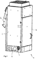
- Fig. 1 shows a trained as a centrifugal dryer separator 1 for separating a solid material from a flow.
- the separator 1 comprises a housing 2 having an inlet 4 for supplying a mixture of a fluid, such as water, and a solid, such as granules.
- the housing 2 has an outlet 6 for discharging the fluid from the housing and an outlet 6 'for discharging the separated solid.
- a pivotally hinged housing door 8 is arranged, with the access to the interior of the separating device 1 is possible.
- a rotor 10 is disposed within the housing 2.
- the rotor 10 is rotatably mounted in the operation of the separating device 1 about a substantially vertical longitudinal axis 10 '.
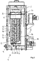
- the housing 2 further has a separating chamber 12 surrounding the rotor, which has a preferably cylindrical shape.
- the separation chamber 12 has a circumferential wall 14 that surrounds the rotor 10 at least in the circumferential direction and in the longitudinal direction. This is defined by a screen body 16.
- the screen 16 is adapted to separate out the solid material from the mixture and to pass the fluid as a component of the mixture in the radial direction through the openings of the screen body 16.
- a fluid-impermeable baffle 17 is further formed, is deflected in particular in the circumferential direction of the separation chamber directly from the inlet region into the separation chamber 12 exiting mixture.
- the rotor 10 is preferably coupled in a rotary manner to a drive 18 embodied as an electric motor.
- the rotor 10 has a plurality of transport elements 20, 20 ', which are arranged in several rows around the longitudinal axis 10' of the rotor 10 around.
- the transport elements 20, 20 ' extend at an angle inclined to the longitudinal axis 10' of the rotor 10.
- the transport elements 20, 20 ' form on the outer circumference of the rotor an outer conveyor section, with which in combination with the circumferentially surrounding screen body 16, a movement of the fixed Stoffes is effected with a transport direction 22 substantially parallel to the longitudinal axis 10 '.
- the transport direction 22 extends in the embodiment shown approximately in the vertical direction from the bottom 24 of the separation chamber 12 to the upper end 26 of the separation chamber.
- the solid is conveyed from an inlet region 28 at the bottom 24 of the separation chamber 12 in the direction of a discharge opening 30 at the upper end 26 of the separation chamber,
- the discharge port 30 is connected to the outlet 6 'for discharging the separated solid.
- the inlet region 28 is formed on the separation chamber 12 that the mixture when entering the separation chamber 12 performs a movement with at least one relative to the longitudinal axis 10 'of the rotor 10 axial component in the transport direction 22.
- the inlet region 28 is arranged on a bottom-side end wall 32 of the separation chamber 12.
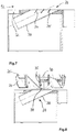
- Fig. 3 shows a first embodiment of the in particular arranged on the bottom end wall 32 of the separation chamber 12 inlet region 28.
- the inlet region 28 is formed on the separation chamber 12, that the mixture during or after entering the separation chamber performs a movement with a tangential and an axial component.
- the mixture is placed in a spiraling motion.
- the inlet region 28 may be arranged at different angles ⁇ , ⁇ 'in the range of preferably 5 to 85 ° to the longitudinal axis of the rotor.
- the inlet region 28 may be arranged at a fixed angle to the bottom end wall 32 of the separation chamber.
- the inlet region 28 ' is adjustably received on the end wall 32 of the separation chamber 12.
- the Fig. 5 to 7 illustrate that in the inlet region 28 of the separation chamber 12 according to various embodiments, one or more guide elements can be arranged with which influence on the inlet angle of the mixture in the inlet region 28 can be taken.
- the guide elements 34, 34 ' which are formed in one embodiment as baffles, have to the inlet axis 36 an inclined orientation.
- the guide element 34 or the guide elements 34, 34 ' is aligned in such an inclined manner to the inlet axis 36 that the mixture enters the separation chamber 12 (FIG. Fig. 2 ) performs a movement in the transport direction, the axial component is significantly larger than without a corresponding guide element.
- the angle of the inlet region relative to the longitudinal axis 10 'of the rotor 10 can be selected to be larger.
- the space required for the inlet region 28 according to the invention is thus kept low below the separation chamber 12.
- FIG. 8 shows, alternatively or optionally, the transport area 20 associated with the intake area 28 on the lowest level of the rotor 10, in the vicinity of the bottom-side end wall 32 of the separation chamber 12 circumferentially, at its front edge 35 have an angled blade section 37.
- the angled blade section 37 has a flattened angle of attack to the rest of the transport element, with respect to the axis of rotation 10 'of the rotor 10. With the angled portion 36, a gentle picking up the introduced via the inlet region 28 into the separation chamber 12 solid substances.
- the inlet region 28 has a pipe section 38, which in the in Fig. 9 embodiment shown at least a portion 40 having a straight course and a portion 40 'having a curved course.
- Fig. 10 shows a possible embodiment of an inlet region 28, which has an inlet axis 36, which is arranged at an angle in the range of about 0 ° with respect to a through the longitudinal axis of the rotor and the inlet region 28 extending main axis 42.
- the introduced into the separation chamber mixture thus has primarily a movement with an axial and a radial component.
- Fig. 11 illustrates that the inlet axis 36 may be aligned inclined to the main axis 42 in an alternative embodiment of the separation device according to the invention. In the present embodiment, the inlet axis 36 is aligned with respect to the main axis 42 at an angle ⁇ of about 35 °.
- the mixture is introduced via the inlet region 28 with a movement in the separation chamber 12, which has an axial, a tangential and a radial component.
- the angle between the inlet axis 36 and the main axis 42 may vary at an angle in the range between 0 and 90 °.
- the inlet region 28 with its inlet axis relative to the main axis 42 is fixed or also adjustable.
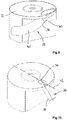
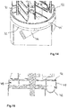
- the Fig. 12 to 14 show embodiments of a separation device according to the invention, wherein in the inlet region 28 'for the separation chamber 12 each have a distribution chamber 44, 44' is provided.
- Each of the distribution chambers 44, 44 ' has an inlet 46 and at least one annular channel 48 arranged inside the distribution chamber (FIG. Fig. 15 ) on.
- the distribution chamber 44 further includes a plurality of axially directed passage openings 50.
- a mixture to be separated within the separation chamber flows into the distribution chamber 44 via the inlet 46.
- the mixture then distributes uniformly over the annular channel 48 in the distribution chamber 44 and then enters via the axial passage openings 50 in the Separating chamber 12 via.
- the passage openings corresponding to the cross section of the inlet 46 adapted free cross sections. In order for a damming of the mixture in the distribution chamber 44 is avoided.
- FIGS. 14 and 15 show an alternative embodiment of the distribution chamber 44 ', which has an annular Ausströmschlitz 52 instead of axial passage openings.
- the outflow slot 52 is arranged in the vicinity of the cylindrical peripheral wall 14 of the separation chamber 12.
- the width of the outflow slot 52 is matched to the grain size of the solid to be separated from the mixture, such as granules.
- Outflow slot 52 in the illustrated embodiment, extends along the entire circumference of distribution chamber 44 'and preferably has a width in the range of about 5 mm to about 25 mm.
Landscapes
- Engineering & Computer Science (AREA)
- Mechanical Engineering (AREA)
- General Engineering & Computer Science (AREA)
- Health & Medical Sciences (AREA)
- Life Sciences & Earth Sciences (AREA)
- Molecular Biology (AREA)
- Centrifugal Separators (AREA)
- Drying Of Solid Materials (AREA)
Priority Applications (5)
| Application Number | Priority Date | Filing Date | Title |
|---|---|---|---|
| EP17199847.9A EP3480542A1 (de) | 2017-11-03 | 2017-11-03 | Trennvorrichtung zum trennen eines gemisches aus einem festen stoff und einem fluid |
| JP2020524367A JP2021501681A (ja) | 2017-11-03 | 2018-11-02 | 固体材料及び流体からなる混合物を分離するためのセパレータ |
| CN201880070725.4A CN111295560B (zh) | 2017-11-03 | 2018-11-02 | 用于分离由固体材料和流体组成的混合物的分离器 |
| PCT/US2018/058973 WO2019090089A1 (en) | 2017-11-03 | 2018-11-02 | Separator for separating a mixture consisting of solid material and a fluid |
| US16/760,488 US20200256619A1 (en) | 2017-11-03 | 2018-11-02 | Separator for separating a mixture consisting of a solid material and a fluid |
Applications Claiming Priority (1)
| Application Number | Priority Date | Filing Date | Title |
|---|---|---|---|
| EP17199847.9A EP3480542A1 (de) | 2017-11-03 | 2017-11-03 | Trennvorrichtung zum trennen eines gemisches aus einem festen stoff und einem fluid |
Publications (1)
| Publication Number | Publication Date |
|---|---|
| EP3480542A1 true EP3480542A1 (de) | 2019-05-08 |
Family
ID=60262763
Family Applications (1)
| Application Number | Title | Priority Date | Filing Date |
|---|---|---|---|
| EP17199847.9A Withdrawn EP3480542A1 (de) | 2017-11-03 | 2017-11-03 | Trennvorrichtung zum trennen eines gemisches aus einem festen stoff und einem fluid |
Country Status (5)
| Country | Link |
|---|---|
| US (1) | US20200256619A1 (enExample) |
| EP (1) | EP3480542A1 (enExample) |
| JP (1) | JP2021501681A (enExample) |
| CN (1) | CN111295560B (enExample) |
| WO (1) | WO2019090089A1 (enExample) |
Families Citing this family (2)
| Publication number | Priority date | Publication date | Assignee | Title |
|---|---|---|---|---|
| AU2019333933A1 (en) | 2018-09-06 | 2021-05-13 | Sand Separation Technologies Inc. | Counterflow vortex breaker |
| WO2025222150A1 (en) * | 2024-04-19 | 2025-10-23 | Alterra Energy, Llc | Online cleaning and fouling prevention in vapor transfer lines and industrial processes |
Citations (3)
| Publication number | Priority date | Publication date | Assignee | Title |
|---|---|---|---|---|
| US5265347A (en) * | 1992-09-04 | 1993-11-30 | Gala Industries, Inc. | Centrifugal pellet dryer |
| US5987769A (en) * | 1996-04-30 | 1999-11-23 | Carter Day International, Inc. | Centrifugal dryer |
| US20080072447A1 (en) * | 2006-09-20 | 2008-03-27 | Econ Maschinenbau Und Steuerungstechnik Gmbh | Device for draining and drying solids, in particular plastics granulated under water |
Family Cites Families (12)
| Publication number | Priority date | Publication date | Assignee | Title |
|---|---|---|---|---|
| DE2622565C3 (de) * | 1976-05-20 | 1982-11-04 | Krauss-Maffei AG, 8000 München | Vorrichtung zum Trocknen von Feststoffpartikeln im Wirbelschichtverfahren |
| US4219409A (en) * | 1977-12-14 | 1980-08-26 | Liller Delbert I | Inlet line deflector and equalizer means for a classifying cyclone used for washing and method of washing using deflectors and equalizers |
| FR2552864B2 (fr) * | 1982-10-05 | 1987-06-12 | Perron Robert | Procede de dessiccation d'un melange liquide ou pateux et appareil pour la mise en oeuvre de ce procede |
| CN101806530B (zh) * | 2009-02-16 | 2012-09-05 | 张学骞 | 一种立式离心脱水机 |
| WO2011005528A1 (en) * | 2009-06-22 | 2011-01-13 | Gala Industries, Inc. | Continuous pelletizing, drying and bagging systems with improved throughput |
| CN103115479A (zh) * | 2011-11-17 | 2013-05-22 | 扬州扬杰电子科技股份有限公司 | 一种离心机 |
| ITMI20120836A1 (it) * | 2012-05-15 | 2013-11-16 | Rinaldo Franceschini | Apparecchiatura di disidratazione per centrifugazione di rifiuti alimentari |
| CN103836888A (zh) * | 2014-03-13 | 2014-06-04 | 巫蔡泉 | 可折叠式雨伞甩干装置与方法 |
| CN105758146B (zh) * | 2016-04-15 | 2017-12-15 | 陈银芳 | 一种高效的矿石烘干装置 |
| CN205909642U (zh) * | 2016-07-07 | 2017-01-25 | 如皋市大昌电子有限公司 | 一种二极管脱水装置 |
| US10557665B2 (en) * | 2016-10-14 | 2020-02-11 | Gala Industries, Inc. | Centrifugal pellet dryer |
| DE202016006421U1 (de) * | 2016-10-17 | 2016-11-07 | Maag Automatik Gmbh | Vorrichtung zur Trocknung von Granulatkörnern |
-
2017
- 2017-11-03 EP EP17199847.9A patent/EP3480542A1/de not_active Withdrawn
-
2018
- 2018-11-02 CN CN201880070725.4A patent/CN111295560B/zh not_active Expired - Fee Related
- 2018-11-02 JP JP2020524367A patent/JP2021501681A/ja not_active Abandoned
- 2018-11-02 WO PCT/US2018/058973 patent/WO2019090089A1/en not_active Ceased
- 2018-11-02 US US16/760,488 patent/US20200256619A1/en not_active Abandoned
Patent Citations (3)
| Publication number | Priority date | Publication date | Assignee | Title |
|---|---|---|---|---|
| US5265347A (en) * | 1992-09-04 | 1993-11-30 | Gala Industries, Inc. | Centrifugal pellet dryer |
| US5987769A (en) * | 1996-04-30 | 1999-11-23 | Carter Day International, Inc. | Centrifugal dryer |
| US20080072447A1 (en) * | 2006-09-20 | 2008-03-27 | Econ Maschinenbau Und Steuerungstechnik Gmbh | Device for draining and drying solids, in particular plastics granulated under water |
Also Published As
| Publication number | Publication date |
|---|---|
| US20200256619A1 (en) | 2020-08-13 |
| JP2021501681A (ja) | 2021-01-21 |
| WO2019090089A1 (en) | 2019-05-09 |
| CN111295560B (zh) | 2022-02-08 |
| CN111295560A (zh) | 2020-06-16 |
Similar Documents
| Publication | Publication Date | Title |
|---|---|---|
| EP0212256B1 (de) | Vorrichtung zum dosierten Auftragen von Schüttgut | |
| EP2155353B1 (de) | Pressschneckenseparator | |
| DE102007043670A1 (de) | Rührwerkskugelmühle | |
| EP2781323B1 (de) | Vorrichtung zum Trocknen von kleinstückigem Material | |
| EP1631371A1 (de) | Vorrichtung zur behandlung von feststoffen | |
| EP0638365B1 (de) | Verfahren und Vorrichtung zur Trennung eines feinkörnigen Feststoffes in zwei Kornfraktionen | |
| DE112018008021T5 (de) | Klassierrotor und Klassiervorrichtung | |
| DE2027028A1 (de) | Siebmaschine für Fasersuspensionen | |
| EP3480542A1 (de) | Trennvorrichtung zum trennen eines gemisches aus einem festen stoff und einem fluid | |
| DE2447360A1 (de) | Vorrichtung zum entfernen von fremdkoerpern von zuckerrueben od.dgl. | |
| WO2011117090A1 (de) | Vollmantel-schneckenzentrifuge | |
| EP3334519B1 (de) | Vorrichtung und verfahren zum dispergieren mindestens einer substanz in einem fluid | |
| DE60021567T2 (de) | Schleuse zum entladen von schüttgut | |
| DD232844A5 (de) | Verfahren und vorrichtung zum trennschleudern von feinkornmineralgemischen | |
| DE2908729A1 (de) | Verfahren an einer siebvorrichtung zum reinigen der oeffnungen in einem siebblech und vorrichtung zur durchfuehrung des verfahrens | |
| DE102014108722A1 (de) | Schneckenzentrifuge | |
| EP1998897A1 (de) | Vorrichtung zur trocknung nassen schüttfähigen gutes, vorzugsweise von kunststoffteilchen | |
| EP0672455B1 (de) | Vorrichtung zum Nassklassieren | |
| DE3209309C2 (enExample) | ||
| DE2239960A1 (de) | Verfahren und vorrichtung zur zerkleinerung und zur probenentnahme von feststoffen | |
| DE102022112948B3 (de) | Zellenradschleuse und Prozessanlage mit einer Zellenradschleuse | |
| WO2011144196A1 (de) | Pulper mit einem zuführraum und einem verdrängerraum | |
| EP2146167B1 (de) | Vorrichtung und Verfahren zum Entfernen von Fluiden | |
| EP3691799B1 (de) | Siebvorrichtung | |
| EP3253554B1 (de) | Stopfschnecke |
Legal Events
| Date | Code | Title | Description |
|---|---|---|---|
| PUAI | Public reference made under article 153(3) epc to a published international application that has entered the european phase |
Free format text: ORIGINAL CODE: 0009012 |
|
| STAA | Information on the status of an ep patent application or granted ep patent |
Free format text: STATUS: THE APPLICATION HAS BEEN PUBLISHED |
|
| AK | Designated contracting states |
Kind code of ref document: A1 Designated state(s): AL AT BE BG CH CY CZ DE DK EE ES FI FR GB GR HR HU IE IS IT LI LT LU LV MC MK MT NL NO PL PT RO RS SE SI SK SM TR |
|
| AX | Request for extension of the european patent |
Extension state: BA ME |
|
| STAA | Information on the status of an ep patent application or granted ep patent |
Free format text: STATUS: REQUEST FOR EXAMINATION WAS MADE |
|
| 17P | Request for examination filed |
Effective date: 20191108 |
|
| RBV | Designated contracting states (corrected) |
Designated state(s): AL AT BE BG CH CY CZ DE DK EE ES FI FR GB GR HR HU IE IS IT LI LT LU LV MC MK MT NL NO PL PT RO RS SE SI SK SM TR |
|
| STAA | Information on the status of an ep patent application or granted ep patent |
Free format text: STATUS: EXAMINATION IS IN PROGRESS |
|
| 17Q | First examination report despatched |
Effective date: 20200211 |
|
| STAA | Information on the status of an ep patent application or granted ep patent |
Free format text: STATUS: THE APPLICATION IS DEEMED TO BE WITHDRAWN |
|
| 18D | Application deemed to be withdrawn |
Effective date: 20220921 |