EP3480542A1 - Separator for separating a mixture of a solid substance and a fluid - Google Patents
Separator for separating a mixture of a solid substance and a fluid Download PDFInfo
- Publication number
- EP3480542A1 EP3480542A1 EP17199847.9A EP17199847A EP3480542A1 EP 3480542 A1 EP3480542 A1 EP 3480542A1 EP 17199847 A EP17199847 A EP 17199847A EP 3480542 A1 EP3480542 A1 EP 3480542A1
- Authority
- EP
- European Patent Office
- Prior art keywords
- separation chamber
- rotor
- mixture
- inlet region
- longitudinal axis
- Prior art date
- Legal status (The legal status is an assumption and is not a legal conclusion. Google has not performed a legal analysis and makes no representation as to the accuracy of the status listed.)
- Withdrawn
Links
Images


Classifications
-
- F—MECHANICAL ENGINEERING; LIGHTING; HEATING; WEAPONS; BLASTING
- F26—DRYING
- F26B—DRYING SOLID MATERIALS OR OBJECTS BY REMOVING LIQUID THEREFROM
- F26B5/00—Drying solid materials or objects by processes not involving the application of heat
- F26B5/08—Drying solid materials or objects by processes not involving the application of heat by centrifugal treatment
-
- F—MECHANICAL ENGINEERING; LIGHTING; HEATING; WEAPONS; BLASTING
- F26—DRYING
- F26B—DRYING SOLID MATERIALS OR OBJECTS BY REMOVING LIQUID THEREFROM
- F26B17/00—Machines or apparatus for drying materials in loose, plastic, or fluidised form, e.g. granules, staple fibres, with progressive movement
- F26B17/18—Machines or apparatus for drying materials in loose, plastic, or fluidised form, e.g. granules, staple fibres, with progressive movement with movement performed by rotating helical blades or other rotary conveyors which may be heated moving materials in stationary chambers, e.g. troughs
- F26B17/22—Machines or apparatus for drying materials in loose, plastic, or fluidised form, e.g. granules, staple fibres, with progressive movement with movement performed by rotating helical blades or other rotary conveyors which may be heated moving materials in stationary chambers, e.g. troughs the axis of rotation being vertical or steeply inclined
-
- B—PERFORMING OPERATIONS; TRANSPORTING
- B29—WORKING OF PLASTICS; WORKING OF SUBSTANCES IN A PLASTIC STATE IN GENERAL
- B29B—PREPARATION OR PRETREATMENT OF THE MATERIAL TO BE SHAPED; MAKING GRANULES OR PREFORMS; RECOVERY OF PLASTICS OR OTHER CONSTITUENTS OF WASTE MATERIAL CONTAINING PLASTICS
- B29B9/00—Making granules
- B29B9/16—Auxiliary treatment of granules
Definitions
- the invention relates to a separation device, in particular a centrifugal dryer, for separating a mixture of a solid material and a fluid, in particular granules and water, with a housing having at least one inlet for supplying the mixture and at least one outlet for discharging the the mixture of separate solid material and / or the fluid, a rotatably mounted within the housing rotor which is adapted to effect by rotation a movement of the solid material with a transport direction substantially along its longitudinal axis, and one defined by at least one screen body Separating chamber in which the rotor is arranged and which has at least one inlet region for the mixture and at least one discharge opening for the solid material.
- a separation device in particular a centrifugal dryer, for separating a mixture of a solid material and a fluid, in particular granules and water
- a housing having at least one inlet for supplying the mixture and at least one outlet for discharging the the mixture of separate solid material and / or the fluid
- Separators of the type described above are used in the prior art for separating a mixture, consisting for example of a solid material and a fluid, into the respective components.
- the mixture of the solid material also referred to as solid
- the fluid is supplied to the separator in particular as a continuous flow.
- the separation devices also known as centrifugal dryers, are used, for example, in the plastics processing industry.
- a plastic granulate is separated from, for example, a water stream which conveys the granules in order to be able to feed the separated granules to further processing or packaging.
- the known separation devices comprise a housing with an inlet for supplying the mixture and at least one outlet for discharging the solid substance and / or the fluid.
- the separation chamber comprises at least one inlet region for the mixture to be introduced therein and at least one outlet opening for the separated solid substance.
- the separation chamber is at least partially formed by a screen body, which is adapted to retain the solid material within the separation chamber, wherein the fluid can pass through the screen body.
- a rotatably mounted rotor is arranged, which causes by rotation at least a movement of the solid material with a transport direction substantially along its longitudinal or rotational axis.
- the inlet region of the separation chamber which may have a cylindrical shape, is usually formed on the peripheral wall of the separation chamber.
- the inlet region often has a pointing in the direction of the bottom of the separation chamber slope.
- the mixture therefore flows automatically into the separation chamber due to the positional energy contained in the mixture.
- the mixture then undergoes a (deflection or reversal) movement in other directions, in particular upwards, by means of the rotor arranged in the separation chamber and rotating.
- the solid material and at least parts of the fluid are moved over a predetermined height of the rotor, in particular along the longitudinal axis of the rotor.
- the solid to be separated may under certain circumstances have abrasive properties and / or contain fillers, such as glass fibers or rock flour, which have abrasive properties.
- fillers such as glass fibers or rock flour
- the invention therefore an object of the invention to provide a separation device for separating a mixture of a solid material and a fluid at which a reduced wear occurs.
- the invention solves its underlying object in a separating device for separating a mixture of a solid material and a fluid, in particular of granules and water, having the features of the subject matter of claim 1.
- the inlet region is formed on the separation chamber such that the mixture, upon entering the separation chamber, performs a movement with at least one axial component in the transport direction with respect to the longitudinal axis of the rotor.
- the invention is based on the finding that, with the aid of the inlet region designed according to the invention, the deflection or deflection movement of the mixture upon entry into the separation chamber is at least reduced or minimized, preferably no deflection movement takes place.
- the wear of, in particular, the lower portion of the rotor is reduced to a minimum even in a separation process of a solid material having abrasive properties from a fluid.
- the life of the rotor and other with the mixture and the solid to be separated out coming in contact reaching components and components can be extended and the distances between possible maintenance intervals on the rotor can be increased.
- the inlet region is formed on the separation chamber such that the mixture is introduced into the separation chamber via the peripheral wall of the separation chamber.
- the inlet region has in particular to the longitudinal axis of the separation chamber and thus to the axis of rotation of the rotor accommodated in the separation chamber in an orientation in which the mixture performs on entering the separation chamber a movement having an axial component which is directed in the same direction as the with the rotor converted transport direction of the solid material.
- the axial component of the movement of the mixture and the transport direction of the solid material are therefore rectified.
- the term "component" is to be understood as part of a movement or as a component of movement.
- the inlet region is formed on the separation chamber, that the mixture is offset during or after entering the separation chamber in a substantially spiral-shaped movement with a tangential and an axial component.
- the mixture performs a spiral movement already on entering the separation chamber.
- the helical introduction of the mixture preferably further reduces the wear in the lower region of the rotor.
- the spiral movement has at least one tangential and one axial component, which in a preferred embodiment may be approximately the same size.
- the axial component of the movement has the same direction as the transport direction of the solid along the rotor.
- the inlet region for the mixture is arranged in a lower portion of the separation chamber, preferably on a bottom end wall, wherein preferably the inlet region is arranged at an angle ⁇ , ⁇ 'in the range of 5 to 85 ° to the longitudinal axis of the rotor.
- the inlet region formed on the separation chamber preferably generates a movement of the mixture introduced into the separation chamber, by means of which the mixture is removed from the rotating rotor while avoiding a deflection movement on the introduced mixture from the inlet region in the direction of the discharge opening.
- a deflection movement is to be understood as meaning a change of at least one movement component in an opposite direction.
- the proportion of the axial component of the movement of the mixture is preferably adjustable.
- the inlet region is arranged on the end wall, preferably the bottom-side end wall of the separation chamber.
- the introduction of the mixture via the bottom-side end wall of the separation chamber has the advantage that the mixture can be introduced via the end wall in a preferred direction in the separation chamber, in which the resulting wear on the rotor through the solid material to be transported from the inlet region in the direction of the discharge opening is further reduced.
- the inlet region is adjustably arranged on the separation chamber, in particular on its bottom end wall.
- the inflow angle of the mixture into the separation chamber is preferably changeable.
- the inflow angle can preferably be adapted individually.
- the ratio between the at least axial component and the tangential component of the movement of the mixture is changed upon entry into the separation chamber.
- a preferred embodiment of the invention provides that in the inlet region, one or more guide elements, preferably baffles are arranged, wherein the guide element is received fixed or adjustable within the inlet region.
- the guide element is received fixed or adjustable within the inlet region.
- the guide element which is preferably designed as a guide plate, can be arranged within the inlet region.
- the guide element is arranged fixed within the inlet region.
- the or the guide elements are adjustably formed in the inlet region.
- the inlet region has an inlet axis, which is arranged at an angle in the range of about 0 to 90 ° relative to a main axis extending through the longitudinal axis of the rotor and the inlet region, which axis is oriented in a plane perpendicular to the longitudinal axis of the rotor.
- an adaptation of the inflow angle, with respect to the longitudinal axis of the rotor, whereby primarily the proportion of the axial component of the inflow movement is adjusted by adjusting the angle between the inflow axis and the main axis, a certain ratio between the tangential and the radial component of the movement of the mixture be adjusted with inflow into the separation chamber.
- the movement of the introduced into the separation chamber mixture in a preferred embodiment of the invention in addition to an axial component on a purely tangential component also includes a tangential and a radial component.
- the inlet axis is designed to be adjustable relative to the main axis extending through the longitudinal axis of the rotor and the inlet region.
- the inlet axis of the inlet region preferably within the above-indicated angle range between 0 and 90 ° in the operation of the separator changeable.
- the inflow behavior of the mixture introduced into the separation chamber can be varied in a simple manner.
- the inflow angle of the mixture can be adjusted individually as a function of the composition and the properties of the mixture to be separated.
- the inlet region has a pipe section which has a rectilinear and / or curved course.
- the connecting piece of the inlet region formed on the separating chamber is formed by means of a particularly cylindrical pipe section.
- the pipe piece has a curved course.
- the mixture introduced into the separation chamber can preferably be introduced spirally. It is also possible to keep the required height for the inlet region at the bottom of the separation chamber low.
- An especially adjustably received on the bottom-side end wall of the separation chamber pipe section is preferably sealed by a sealing element to the end wall of the separation chamber.
- the pipe section at least partially forming the inlet region is firmly connected to the bottom-side end wall, preferably materially.
- a plurality of inlet regions are formed on the end face of the separation chamber, which are preferably arranged uniformly spaced around the longitudinal axis of the rotor around.
- the introduction of the mixture preferably takes place via a plurality of inlet regions with which a uniform flow or a uniform flow pattern is generated in the lower region of the separation chamber.
- the inlet regions are arranged symmetrically about the longitudinal axis of the rotor, in particular the bottom-side end wall of the separation chamber.
- the inlet region has a distribution chamber with a circumferential annular channel and preferably a plurality of axially directed passage openings and / or an annular outflow slot.
- the inlet region according to the invention thus has a kind of pre-chamber.
- the distribution chamber is filled uniformly with the mixture via the inlet fluid-coupled with the distribution chamber inlet. From the filled distributor chamber, the mixture is then preferably via feedthrough openings or the annular outflow slot in substantially the transport direction along of the rotor introduced into the separation chamber.
- the passage openings are preferably arranged distributed uniformly on, for example, a pitch circle diameter of the circular end wall about its center axis to each other.
- the distribution chamber instead of the passage openings, as a transition in the direction of the separation chamber on an annular Ausströmschlitz.
- the outflow slot is preferably arranged close to the inside of the cylindrical peripheral wall of the separating chamber formed by the screen body and preferably has a width in the range of about 5 mm to about 25 mm. In one possible embodiment of the invention, the cylindrical peripheral wall is completely formed by the screen body.
- a fluid-impermeable baffle surface is provided on the peripheral wall of the separation chamber in the inlet region.
- the baffle serves as an impact surface for the mixture immediately after it has been introduced into the separation chamber.
- the baffle is a closed surface element which does not separate the mixture, but rather redirects the mixture as a whole into a preferably spiral movement within the separation chamber. Furthermore, the area of the peripheral wall of the separation chamber has increased strength due to the closed impact surface.
- the rotor has a plurality of preferably lamellar transport elements.
- the transport elements also known as lifting elements, are preferably arranged in several rows around the longitudinal axis and / or aligned at an angle inclined to the longitudinal axis of the rotor.
- the solid material is preferably moved substantially along the longitudinal axis of the rotor.
- the rotation of the rotor also acts on the mixture acting in a radial direction centrifugal force, which pushes out the liquid phase of the mixture radially outwardly over the strainer body of the separation chamber from derselbigen.
- the rotor has a substantially vertical longitudinal axis, so that with the transport elements a transport movement takes place over a predetermined height, which simplifies the separation of the solid material from the fluid, which falls by gravity outside the separation chamber automatically down.
- the longitudinal axis of the rotor and thus the device according to the invention can be inclined overall to the vertical, for example at an angle of up to about 30 ° to the vertical.
- the rotor preferably has four, five, six or more rows of transport elements uniformly distributed over the circumference of the rotor.
- Each transport element is a kind of surface element which extends radially outwardly and in particular is inclined at an angle in the range between 20 and 70 ° to the longitudinal axis of the rotor body.
- the outer peripheral surface of the uniformly distributed over the rotor transport elements has an adapted to the inside of the separation chamber outer contour.
- the outer peripheral surface of the rotor is cylindrical.
- the transport elements are at least partially curved and / or have on their pointing in the direction of rotation leading edge on an angled portion with a flattened angle. Due to the curved contour or the angled section on the transport elements, also referred to as lifting elements, there is a gradual or stepwise deflection of the movement of the solid material in the transport direction. Thus, the wear on the rotor can be further reduced overall.
- the angled portion of the transport element is designed to be adjustable in the region of its front edge. Accordingly, the angle of attack of the flattened portion can be adjusted individually.
- the angled portion based on the remaining portion of the transport element, at an angle in the range of -10 ° and + 30 ° adjustable.
- the rotational movement of the rotor is adapted to the flow velocity of the introduced mixture such that a relative speed between the rotor and the introduced mixture is provided.
- the transport elements move slightly faster than the introduced mixture and in particular the solids contained therein. As a result, the discharge of the mixture from the inlet region of the separation chamber is supported.
- Another aspect of the invention relates to a separation chamber for a separation device, in particular for receiving a rotor of a centrifugal dryer, with at least one inlet region for a einleitbares into the separation chamber mixture of a solid material and a fluid, at least partially circumferentially surrounding a rotor screen body for separating the Fluids and solid, and a discharge opening for the solid material.
- the invention also solves the problem underlying the inventive separation chamber in that the inlet region is formed on the separation chamber such that the mixture performs a movement with at least one axial component relative to the longitudinal axis in the transport direction during operation when entering the separation chamber, wherein the separation chamber is preferably designed according to one of claims 1 to 11.
- the separation chamber preferably has the inlet region for the mixture to be introduced into the separation chamber on a bottom-side end wall.
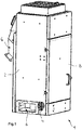
- Fig. 1 shows a trained as a centrifugal dryer separator 1 for separating a solid material from a flow.
- the separator 1 comprises a housing 2 having an inlet 4 for supplying a mixture of a fluid, such as water, and a solid, such as granules.
- the housing 2 has an outlet 6 for discharging the fluid from the housing and an outlet 6 'for discharging the separated solid.
- a pivotally hinged housing door 8 is arranged, with the access to the interior of the separating device 1 is possible.
- a rotor 10 is disposed within the housing 2.
- the rotor 10 is rotatably mounted in the operation of the separating device 1 about a substantially vertical longitudinal axis 10 '.
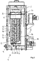
- the housing 2 further has a separating chamber 12 surrounding the rotor, which has a preferably cylindrical shape.
- the separation chamber 12 has a circumferential wall 14 that surrounds the rotor 10 at least in the circumferential direction and in the longitudinal direction. This is defined by a screen body 16.
- the screen 16 is adapted to separate out the solid material from the mixture and to pass the fluid as a component of the mixture in the radial direction through the openings of the screen body 16.
- a fluid-impermeable baffle 17 is further formed, is deflected in particular in the circumferential direction of the separation chamber directly from the inlet region into the separation chamber 12 exiting mixture.
- the rotor 10 is preferably coupled in a rotary manner to a drive 18 embodied as an electric motor.
- the rotor 10 has a plurality of transport elements 20, 20 ', which are arranged in several rows around the longitudinal axis 10' of the rotor 10 around.
- the transport elements 20, 20 ' extend at an angle inclined to the longitudinal axis 10' of the rotor 10.
- the transport elements 20, 20 ' form on the outer circumference of the rotor an outer conveyor section, with which in combination with the circumferentially surrounding screen body 16, a movement of the fixed Stoffes is effected with a transport direction 22 substantially parallel to the longitudinal axis 10 '.
- the transport direction 22 extends in the embodiment shown approximately in the vertical direction from the bottom 24 of the separation chamber 12 to the upper end 26 of the separation chamber.
- the solid is conveyed from an inlet region 28 at the bottom 24 of the separation chamber 12 in the direction of a discharge opening 30 at the upper end 26 of the separation chamber,
- the discharge port 30 is connected to the outlet 6 'for discharging the separated solid.
- the inlet region 28 is formed on the separation chamber 12 that the mixture when entering the separation chamber 12 performs a movement with at least one relative to the longitudinal axis 10 'of the rotor 10 axial component in the transport direction 22.
- the inlet region 28 is arranged on a bottom-side end wall 32 of the separation chamber 12.
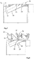
- Fig. 3 shows a first embodiment of the in particular arranged on the bottom end wall 32 of the separation chamber 12 inlet region 28.
- the inlet region 28 is formed on the separation chamber 12, that the mixture during or after entering the separation chamber performs a movement with a tangential and an axial component.
- the mixture is placed in a spiraling motion.
- the inlet region 28 may be arranged at different angles ⁇ , ⁇ 'in the range of preferably 5 to 85 ° to the longitudinal axis of the rotor.
- the inlet region 28 may be arranged at a fixed angle to the bottom end wall 32 of the separation chamber.
- the inlet region 28 ' is adjustably received on the end wall 32 of the separation chamber 12.
- the Fig. 5 to 7 illustrate that in the inlet region 28 of the separation chamber 12 according to various embodiments, one or more guide elements can be arranged with which influence on the inlet angle of the mixture in the inlet region 28 can be taken.
- the guide elements 34, 34 ' which are formed in one embodiment as baffles, have to the inlet axis 36 an inclined orientation.
- the guide element 34 or the guide elements 34, 34 ' is aligned in such an inclined manner to the inlet axis 36 that the mixture enters the separation chamber 12 (FIG. Fig. 2 ) performs a movement in the transport direction, the axial component is significantly larger than without a corresponding guide element.
- the angle of the inlet region relative to the longitudinal axis 10 'of the rotor 10 can be selected to be larger.
- the space required for the inlet region 28 according to the invention is thus kept low below the separation chamber 12.
- FIG. 8 shows, alternatively or optionally, the transport area 20 associated with the intake area 28 on the lowest level of the rotor 10, in the vicinity of the bottom-side end wall 32 of the separation chamber 12 circumferentially, at its front edge 35 have an angled blade section 37.
- the angled blade section 37 has a flattened angle of attack to the rest of the transport element, with respect to the axis of rotation 10 'of the rotor 10. With the angled portion 36, a gentle picking up the introduced via the inlet region 28 into the separation chamber 12 solid substances.
- the inlet region 28 has a pipe section 38, which in the in Fig. 9 embodiment shown at least a portion 40 having a straight course and a portion 40 'having a curved course.
- Fig. 10 shows a possible embodiment of an inlet region 28, which has an inlet axis 36, which is arranged at an angle in the range of about 0 ° with respect to a through the longitudinal axis of the rotor and the inlet region 28 extending main axis 42.
- the introduced into the separation chamber mixture thus has primarily a movement with an axial and a radial component.
- Fig. 11 illustrates that the inlet axis 36 may be aligned inclined to the main axis 42 in an alternative embodiment of the separation device according to the invention. In the present embodiment, the inlet axis 36 is aligned with respect to the main axis 42 at an angle ⁇ of about 35 °.
- the mixture is introduced via the inlet region 28 with a movement in the separation chamber 12, which has an axial, a tangential and a radial component.
- the angle between the inlet axis 36 and the main axis 42 may vary at an angle in the range between 0 and 90 °.
- the inlet region 28 with its inlet axis relative to the main axis 42 is fixed or also adjustable.
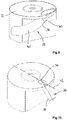
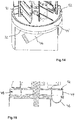
- the Fig. 12 to 14 show embodiments of a separation device according to the invention, wherein in the inlet region 28 'for the separation chamber 12 each have a distribution chamber 44, 44' is provided.
- Each of the distribution chambers 44, 44 ' has an inlet 46 and at least one annular channel 48 arranged inside the distribution chamber (FIG. Fig. 15 ) on.
- the distribution chamber 44 further includes a plurality of axially directed passage openings 50.
- a mixture to be separated within the separation chamber flows into the distribution chamber 44 via the inlet 46.
- the mixture then distributes uniformly over the annular channel 48 in the distribution chamber 44 and then enters via the axial passage openings 50 in the Separating chamber 12 via.
- the passage openings corresponding to the cross section of the inlet 46 adapted free cross sections. In order for a damming of the mixture in the distribution chamber 44 is avoided.
- FIGS. 14 and 15 show an alternative embodiment of the distribution chamber 44 ', which has an annular Ausströmschlitz 52 instead of axial passage openings.
- the outflow slot 52 is arranged in the vicinity of the cylindrical peripheral wall 14 of the separation chamber 12.
- the width of the outflow slot 52 is matched to the grain size of the solid to be separated from the mixture, such as granules.
- Outflow slot 52 in the illustrated embodiment, extends along the entire circumference of distribution chamber 44 'and preferably has a width in the range of about 5 mm to about 25 mm.
Abstract
Die Erfindung betrifft eine Trennvorrichtung (1), insbesondere einen Zentrifugaltrockner, zum Trennen eines Gemisches aus einem festen Stoff und einem Fluid, insbesondere von Granulat und Wasser, mit einem Gehäuse (2), welches mindestens einen Einlass (4) zum Zuführen des Gemisches und mindestens einen Auslass (6, 6') zum Abführen des von dem Gemisch getrennten festen Stoffes und/oder des Fluids aufweist, einem innerhalb des Gehäuses (2) drehbar gelagerten Rotor (10), der dazu eingerichtet ist, durch Drehung eine Bewegung des festen Stoffes mit einer Transportrichtung im Wesentlichen entlang seiner Längsachse (10') zu bewirken, und einer durch mindestens einen Siebkörper (16) definierten Trennkammer (12), in welcher der Rotor (10) angeordnet ist und die mindestens einen Einlaufbereich (28, 28') für das Gemisch und zumindest eine Ausgabeöffnung (30) für den festen Stoff aufweist. Der Einlaufbereich (28, 28') ist so an der Trennkammer (12) ausgebildet, dass das Gemisch bei Eintritt in die Trennkammer (12) eine Bewegung mit zumindest einer bezogen auf die Längsachse (10') des Rotors (10) axialen Komponente in Transportrichtung (22) ausführt.The invention relates to a separating device (1), in particular a centrifugal dryer, for separating a mixture of a solid material and a fluid, in particular of granules and water, with a housing (2) having at least one inlet (4) for supplying the mixture and at least one outlet (6, 6 ') for discharging the solid separated from the mixture and / or the fluid, a rotor (10) rotatably mounted within the housing (2) and adapted to rotate the solid by rotation Substance with a transport direction substantially along its longitudinal axis (10 ') to effect, and by at least one screen body (16) defined separation chamber (12) in which the rotor (10) is arranged and the at least one inlet region (28, 28' ) for the mixture and at least one discharge opening (30) for the solid material. The inlet region (28, 28 ') is formed on the separation chamber (12) such that upon entering the separation chamber (12) the mixture moves with at least one axial component in relation to the longitudinal axis (10') of the rotor (10) Carrying direction (22) performs.
Description
Die Erfindung bezieht sich auf eine Trennvorrichtung, insbesondere einen Zentrifugaltrockner, zum Trennen eines Gemisches aus einem festen Stoff und einem Fluid, insbesondere von Granulat und Wasser, mit einem Gehäuse, welches mindestens einen Einlass zum Zuführen des Gemisches und mindestens einen Auslass zum Abführen des von dem Gemisch getrennten festen Stoffes und/oder des Fluids aufweist, einem innerhalb des Gehäuses drehbar gelagerten Rotor, der dazu eingerichtet ist, durch Drehung eine Bewegung des festen Stoffes mit einer Transportrichtung im Wesentlichen entlang seiner Längsachse zu bewirken, und einer durch mindestens einen Siebkörper definierten Trennkammer, in welcher der Rotor angeordnet ist und die mindestens einen Einlaufbereich für das Gemisch und zumindest eine Ausgabeöffnung für den festen Stoff aufweist.The invention relates to a separation device, in particular a centrifugal dryer, for separating a mixture of a solid material and a fluid, in particular granules and water, with a housing having at least one inlet for supplying the mixture and at least one outlet for discharging the the mixture of separate solid material and / or the fluid, a rotatably mounted within the housing rotor which is adapted to effect by rotation a movement of the solid material with a transport direction substantially along its longitudinal axis, and one defined by at least one screen body Separating chamber in which the rotor is arranged and which has at least one inlet region for the mixture and at least one discharge opening for the solid material.
Trennvorrichtungen der vorbezeichneten Art werden im Stand der Technik zum Trennen eines Gemisches, bestehend zum Beispiel aus einem festen Stoff und einem Fluid, in die jeweiligen Bestandteile eingesetzt. Das Gemisch aus dem festen Stoff, auch bezeichnet als Feststoff, und dem Fluid wird der Trennvorrichtung insbesondere als kontinuierlicher Förderstrom zugeführt. Die auch als Zentrifugaltrockner bekannten Trennvorrichtungen werden beispielsweise in der kunststoffverarbeitenden Industrie verwendet. Mittels einer derartigen Trennvorrichtung wird zum Beispiel ein Kunststoff-Granulat aus beispielsweise einem das Granulat fördernden Wasserstrom separiert, um das separierte Granulat einer Weiterverarbeitung oder Verpackung zuführen zu können.Separators of the type described above are used in the prior art for separating a mixture, consisting for example of a solid material and a fluid, into the respective components. The mixture of the solid material, also referred to as solid, and the fluid is supplied to the separator in particular as a continuous flow. The separation devices, also known as centrifugal dryers, are used, for example, in the plastics processing industry. By means of such a separating device, for example, a plastic granulate is separated from, for example, a water stream which conveys the granules in order to be able to feed the separated granules to further processing or packaging.
Die bekannten Trennvorrichtungen weisen insbesondere ein Gehäuse mit einem Einlass zum Zuführen des Gemisches und mindestens einem Auslass zum Abführen des festen Stoffes und/oder des Fluids auf. Die Trennkammer umfasst zumindest einen Einlaufbereich für das darin einzuleitende Gemisch und zumindest eine Ausgabeöffnung für den separierten festen Stoff. Die Trennkammer wird zumindest bereichsweise durch einen Siebkörper ausgebildet, der dazu eingerichtet ist, den festen Stoff innerhalb der Trennkammer zurückzuhalten, wobei das Fluid durch den Siebkörper hindurchtreten kann. Innerhalb der Trennkammer ist ein drehbar gelagerter Rotor angeordnet, der durch Drehung eine Bewegung zumindest des festen Stoffes mit einer Transportrichtung im Wesentlichen entlang seiner Längs- bzw. Rotationsachse bewirkt.In particular, the known separation devices comprise a housing with an inlet for supplying the mixture and at least one outlet for discharging the solid substance and / or the fluid. The separation chamber comprises at least one inlet region for the mixture to be introduced therein and at least one outlet opening for the separated solid substance. The separation chamber is at least partially formed by a screen body, which is adapted to retain the solid material within the separation chamber, wherein the fluid can pass through the screen body. Within the separation chamber, a rotatably mounted rotor is arranged, which causes by rotation at least a movement of the solid material with a transport direction substantially along its longitudinal or rotational axis.
Der Einlaufbereich der Trennkammer, welche eine zylindrische Form aufweisen kann, ist üblicherweise an der Umfangswandung der Trennkammer ausgebildet. Der Einlaufbereich weist häufig ein in Richtung des Bodens der Trennkammer weisendes Gefälle auf. Das Gemisch strömt daher, aufgrund der im Gemisch enthaltenen Lageenergie, selbsttätig in die Trennkammer hinein. Das Gemisch erfährt dann mittels des in der Trennkammer angeordneten und sich drehenden Rotors eine (Umlenk- oder Umkehr-) Bewegung in andere Richtungen, insbesondere nach oben. Der feste Stoff und zumindest Teile des Fluids werden über eine vorbestimmte Höhe des Rotors insbesondere entlang der Längsachse des Rotors bewegt.The inlet region of the separation chamber, which may have a cylindrical shape, is usually formed on the peripheral wall of the separation chamber. The inlet region often has a pointing in the direction of the bottom of the separation chamber slope. The mixture therefore flows automatically into the separation chamber due to the positional energy contained in the mixture. The mixture then undergoes a (deflection or reversal) movement in other directions, in particular upwards, by means of the rotor arranged in the separation chamber and rotating. The solid material and at least parts of the fluid are moved over a predetermined height of the rotor, in particular along the longitudinal axis of the rotor.
Der zu separierende Feststoff kann unter Umständen abrasive Eigenschaften aufweisen und/oder Füllstoffe enthalten, wie beispielsweise Glasfasern oder Gesteinsmehl, die abrasive Eigenschaften haben. Bei der Umlenk-Bewegung des Gemisches nach dem Einleiten in die Trennkammer kann im unteren Abschnitt des Rotors im Vergleich zu den oberen Abschnitten ein deutlich höherer Verscheiß am Rotor auftreten. Der Verschleiß macht eine Wartung in regelmäßigen Zeitintervallen notwendig, die mit entsprechenden Stillstandszeiten etwaiger vor- oder nachgeschalteter Komponenten einer zum Beispiel kunststoffverarbeitenden Anlage verbunden ist.The solid to be separated may under certain circumstances have abrasive properties and / or contain fillers, such as glass fibers or rock flour, which have abrasive properties. During the deflection movement of the mixture after it has been introduced into the separation chamber, a significantly higher amount of rotor fissure can occur in the lower section of the rotor compared to the upper sections. The wear makes maintenance at regular time intervals necessary, which is associated with corresponding downtime of any upstream or downstream components of a, for example, plastic processing plant.
Der Erfindung lag daher die Aufgabe zugrunde, eine Trennvorrichtung zum Trennen eines Gemisches aus einem festen Stoff und einem Fluid anzugeben, an dem ein verringerter Verschleiß auftritt.The invention therefore an object of the invention to provide a separation device for separating a mixture of a solid material and a fluid at which a reduced wear occurs.
Die Erfindung löst die ihr zugrundeliegende Aufgabe bei einer Trennvorrichtung zum Trennen eines Gemisches aus einem festen Stoff und einem Fluid, insbesondere von Granulat und Wasser, mit den Merkmalen des Gegenstands von Anspruch 1. Insbesondere ist der Einlaufbereich so an der Trennkammer ausgebildet, dass das Gemisch bei Eintritt in die Trennkammer eine Bewegung mit zumindest einer bezogen auf die Längsachse des Rotors axialen Komponente in Transportrichtung ausführt.The invention solves its underlying object in a separating device for separating a mixture of a solid material and a fluid, in particular of granules and water, having the features of the subject matter of
Der Erfindung liegt die Erkenntnis zugrunde, dass mithilfe des erfindungsgemäß ausgebildeten Einlaufbereiches die Umlenkung oder Umlenk-Bewegung des Gemisches bei Eintritt in die Trennkammer zumindest verringert oder minimiert ist, vorzugsweise keine Umlenkbewegung mehr erfolgt. Damit ist der Verschleiß von insbesondere dem unteren Abschnitt des Rotors selbst bei einem Trennvorgang eines festen Stoffes mit abrasiven Eigenschaften aus einem Fluid auf ein Minimum reduziert. Damit kann die Standzeit des Rotors und anderer mit dem Gemisch und dem daraus heraus zu trennenden Feststoffs in Kontakt gelangender Bauteile und Komponenten verlängert und die Abstände zwischen möglichen Wartungsintervallen am Rotor vergrößert werden. In einer möglichen Ausführungsform der Erfindung ist der Einlaufbereich so an der Trennkammer ausgebildet, dass das Gemisch über die Umfangswandung der Trennkammer in die Trennkammer eingeleitet wird. Der Einlaufbereich weist insbesondere zur Längsachse der Trennkammer und damit zur Drehachse des in der Trennkammer aufgenommenen Rotors eine Ausrichtung auf, in der das Gemisch bei Eintritt in die Trennkammer eine Bewegung ausführt, die eine axiale Komponente hat, welche in dieselbe Richtung gerichtet ist, wie die mit dem Rotor umgesetzte Transportrichtung des festen Materials. Die axiale Komponente der Bewegung des Gemisches und die Transportrichtung des festen Materials sind demnach gleichgerichtet. Vorliegend ist der Begriff "Komponente" als Teil einer Bewegung bzw. als Bewegungskomponente zu verstehen.The invention is based on the finding that, with the aid of the inlet region designed according to the invention, the deflection or deflection movement of the mixture upon entry into the separation chamber is at least reduced or minimized, preferably no deflection movement takes place. Thus, the wear of, in particular, the lower portion of the rotor is reduced to a minimum even in a separation process of a solid material having abrasive properties from a fluid. Thus, the life of the rotor and other with the mixture and the solid to be separated out coming in contact reaching components and components can be extended and the distances between possible maintenance intervals on the rotor can be increased. In one possible embodiment of the invention, the inlet region is formed on the separation chamber such that the mixture is introduced into the separation chamber via the peripheral wall of the separation chamber. The inlet region has in particular to the longitudinal axis of the separation chamber and thus to the axis of rotation of the rotor accommodated in the separation chamber in an orientation in which the mixture performs on entering the separation chamber a movement having an axial component which is directed in the same direction as the with the rotor converted transport direction of the solid material. The axial component of the movement of the mixture and the transport direction of the solid material are therefore rectified. In the present case, the term "component" is to be understood as part of a movement or as a component of movement.
Gemäß einer bevorzugten Ausführungsform der Erfindung ist der Einlaufbereich so an der Trennkammer ausgebildet, dass das Gemisch bei oder nach Eintritt in die Trennkammer in eine im Wesentlichen spiralförmige Bewegung mit einer tangentialen und einer axialen Komponente versetzt ist. Bevorzugt führt das Gemisch bereits bei Eintritt in die Trennkammer eine spiralförmige Bewegung aus. Dadurch wird das Gemisch nur noch geringfügig in der Trennkammer durch den sich drehenden Rotor umgelenkt. Das spiralförmige Einleiten des Gemisches verringert vorzugsweise den Verschleiß im unteren Bereich des Rotors weiter. Die spiralförmige Bewegung weist zumindest eine tangentiale und eine axiale Komponente auf, welche in einer bevorzugten Ausführungsform etwa gleich groß sein können. Die axiale Komponente der Bewegung hat dieselbe Richtung, wie die Transportrichtung des Feststoffes entlang des Rotors.According to a preferred embodiment of the invention, the inlet region is formed on the separation chamber, that the mixture is offset during or after entering the separation chamber in a substantially spiral-shaped movement with a tangential and an axial component. Preferably, the mixture performs a spiral movement already on entering the separation chamber. As a result, the mixture is deflected only slightly in the separation chamber by the rotating rotor. The helical introduction of the mixture preferably further reduces the wear in the lower region of the rotor. The spiral movement has at least one tangential and one axial component, which in a preferred embodiment may be approximately the same size. The axial component of the movement has the same direction as the transport direction of the solid along the rotor.
Vorzugsweise ist der Einlaufbereich für das Gemisch in einem unteren Abschnitt der Trennkammer angeordnet, vorzugsweise an einer bodenseitigen Stirnwand, wobei bevorzugt der Einlaufbereich in einem Winkel α, α' im Bereich von 5 bis 85° zur Längsachse des Rotors angeordnet ist. Innerhalb des angegebenen Winkelbereiches erzeugt der an der Trennkammer ausgebildete Einlaufbereich vorzugsweise eine Bewegung des in die Trennkammer eingeleiteten Gemisches, mittels der das Gemisch von dem sich drehenden Rotor, unter Vermeidung einer Umlenkbewegung am eingeleiteten Gemisch vom Einlaufbereich in Richtung der Ausgabeöffnung abgeführt wird. Vorliegend ist unter einer Umlenkbewegung eine Änderung wenigstens einer Bewegungskomponente in eine entgegengesetzte Richtung zu verstehen. In Abhängigkeit vom Winkel des Einlaufbereiches relativ zur Längsachse des Rotors ist bevorzugt der Anteil der axialen Komponente der Bewegung des Gemisches einstellbar. Je geringer der Winkel desto größer ist die axiale Komponente. Durch die Rotation des Rotors wirkt eine Zentrifugalkraft auf das in die Trennkammer eingeleitete Gemisch, wobei das Gemisch in Richtung des die Trennkammer definierenden Siebkörpers nach außen bewegt wird. Das Fluid tritt aufgrund der wirkenden Zentrifugalkraft durch den Siebkörper hindurch, wobei der feste Stoff auf der Innenseite des Siebkörpers zurückgehalten wird und mittels des Rotors in Transportrichtung bewegt wird.Preferably, the inlet region for the mixture is arranged in a lower portion of the separation chamber, preferably on a bottom end wall, wherein preferably the inlet region is arranged at an angle α, α 'in the range of 5 to 85 ° to the longitudinal axis of the rotor. Within the specified angle range, the inlet region formed on the separation chamber preferably generates a movement of the mixture introduced into the separation chamber, by means of which the mixture is removed from the rotating rotor while avoiding a deflection movement on the introduced mixture from the inlet region in the direction of the discharge opening. In the present case, a deflection movement is to be understood as meaning a change of at least one movement component in an opposite direction. Depending on the angle of the inlet region relative to the longitudinal axis of the rotor, the proportion of the axial component of the movement of the mixture is preferably adjustable. The smaller the angle, the larger the axial component. As a result of the rotation of the rotor, a centrifugal force acts on the mixture introduced into the separation chamber, the mixture being moved outward in the direction of the sieve body defining the separation chamber. The fluid passes through the sieve body due to the centrifugal force acting, the solid being retained on the inside of the sieve body and moved in the direction of transport by the rotor.
Bevorzugt ist der Einlaufbereich an der Stirnwand, vorzugsweise der bodenseitigen Stirnwand der Trennkammer angeordnet. Das Einleiten des Gemisches über die bodenseitige Stirnwand der Trennkammer birgt den Vorteil, dass das Gemisch über die Stirnwand in einer Vorzugsrichtung in die Trennkammer eingeleitet werden kann, bei der der entstehende Verschleiß am Rotor durch den vom Einlaufbereich in Richtung der Ausgabeöffnung zu transportierenden festen Stoff auf weiter verringert wird.Preferably, the inlet region is arranged on the end wall, preferably the bottom-side end wall of the separation chamber. The introduction of the mixture via the bottom-side end wall of the separation chamber has the advantage that the mixture can be introduced via the end wall in a preferred direction in the separation chamber, in which the resulting wear on the rotor through the solid material to be transported from the inlet region in the direction of the discharge opening is further reduced.
Gemäß einer bevorzugten Weiterbildung der Erfindung ist vorgesehen, dass der Einlaufbereich verstellbar an der Trennkammer, insbesondere an deren bodenseitigen Stirnwand, angeordnet ist. Mit dem verstellbar angeordneten Einlaufbereich ist der Einströmwinkel des Gemisches in die Trennkammer bevorzugt veränderbar. Insbesondere in Abhängigkeit der mittels der Trennvorrichtung umzusetzenden Parameter wie beispielsweise Drehzahl des Rotors bzw. Größe des zu separierenden Förderstromes, kann der Einströmwinkel bevorzugt individuell angepasst werden. Insbesondere in Abhängigkeit von den Eigenschaften des zu separierenden festen Stoffes, wie beispielsweise Größe oder Dichte des Stoffes, wird das Verhältnis zwischen der zumindest axialen Komponente und der tangentialen Komponente der Bewegung des Gemisches bei Eintritt in die Trennkammer verändert.According to a preferred embodiment of the invention it is provided that the inlet region is adjustably arranged on the separation chamber, in particular on its bottom end wall. With the adjustably arranged inlet region, the inflow angle of the mixture into the separation chamber is preferably changeable. In particular, depending on the parameters to be converted by means of the separating device, such as, for example, the rotational speed of the rotor or the size of the flow to be separated, the inflow angle can preferably be adapted individually. In particular, depending on the properties of the solid to be separated, such as size or density of the substance, the ratio between the at least axial component and the tangential component of the movement of the mixture is changed upon entry into the separation chamber.
Eine bevorzugte Weiterbildung der Erfindung sieht vor, dass im Einlaufbereich ein oder mehrere Leitelemente, vorzugsweise Leitbleche angeordnet sind, wobei das Leitelement feststehend oder verstellbar innerhalb des Einlaufbereiches aufgenommen ist. Mithilfe eines im Einlaufbereich angeordneten Leitelementes kann das in die Trennkammer eingeleitete Gemisch unabhängig von der Ausrichtung des Einlaufbereiches selbst auf vorteilhafte Weise umgeleitet bzw. der Einströmwinkel des Gemisches mit dem Leitelement bevorzugt angepasst werden. Das Leitelement, welches bevorzugt als Leitblech ausgebildet ist, kann innerhalb des Einlaufbereiches angeordnet sein. Mittels des Leitelements ist zumindest eine geringfügige Querschnittsverringerung im Einlaufbereich der Trennkammer bewirkt. Durch die Querschnittsverringerung wird die Strömungsgeschwindigkeit des einströmenden Gemisches erhöht.A preferred embodiment of the invention provides that in the inlet region, one or more guide elements, preferably baffles are arranged, wherein the guide element is received fixed or adjustable within the inlet region. With the aid of a guide element arranged in the inlet region, the mixture introduced into the separation chamber can be redirected in an advantageous manner, independently of the orientation of the inlet region, or the inlet angle of the mixture with the guide element can preferably be adjusted. The guide element, which is preferably designed as a guide plate, can be arranged within the inlet region. By means of the guide element, at least a slight cross-sectional reduction in the inlet region of the separation chamber is effected. The cross-sectional reduction increases the flow velocity of the inflowing mixture.
In einer Ausführungsform der vorliegenden Erfindung ist das Leitelement feststehend innerhalb des Einlaufbereiches angeordnet. Gemäß einer anderen bevorzugten Ausführungsform ist das oder sind die Leitelemente verstellbar im Einlaufbereich ausgebildet. Damit ist eine individuelle Anpassung des Einströmwinkels des Gemisches in die Trennkammer, insbesondere in Abhängigkeit von den Eigenschaften bzw. der Zusammensetzung des in die Trennkammer eingeleiteten Gemisches möglich.In one embodiment of the present invention, the guide element is arranged fixed within the inlet region. According to another preferred embodiment, the or the guide elements are adjustably formed in the inlet region. For an individual adjustment of the inflow angle of the mixture in the separation chamber, in particular depending on the properties or the composition of the introduced into the separation chamber mixture is possible.
Bevorzugt weist der Einlaufbereich eine Einlaufachse auf, die bezogen auf eine durch die Längsachse des Rotors und den Einlaufbereich verlaufende Hauptachse, welche in einer Ebene senkrecht zur Längsachse des Rotors ausgerichtet ist, in einem Winkel im Bereich von etwa 0 bis 90° angeordnet ist. Neben einer Anpassung des Einströmwinkels, bezogen auf die Längsachse des Rotors, wodurch vornehmlich der Anteil der axialen Komponente der Einströmbewegung angepasst wird, kann durch Anpassen des Winkels zwischen der Einlaufachse und der Hauptachse ein bestimmtes Verhältnis zwischen der tangentialen und der radialen Komponente der Bewegung des Gemisches mit Einströmen in die Trennkammer eingestellt werden. Damit weist die Bewegung des in die Trennkammer eingeleiteten Gemisches in einer bevorzugten Ausführungsform der Erfindung neben einer axialen Komponente eine rein tangentiale Komponente auf. In einer anderen Ausführungsform der Erfindung beinhaltet die Bewegung des in die Trennkammer eingeleiteten Gemisches neben einer axialen Komponente ebenfalls eine tangentiale und eine radiale Komponente.Preferably, the inlet region has an inlet axis, which is arranged at an angle in the range of about 0 to 90 ° relative to a main axis extending through the longitudinal axis of the rotor and the inlet region, which axis is oriented in a plane perpendicular to the longitudinal axis of the rotor. In addition to an adaptation of the inflow angle, with respect to the longitudinal axis of the rotor, whereby primarily the proportion of the axial component of the inflow movement is adjusted, by adjusting the angle between the inflow axis and the main axis, a certain ratio between the tangential and the radial component of the movement of the mixture be adjusted with inflow into the separation chamber. Thus, the movement of the introduced into the separation chamber mixture in a preferred embodiment of the invention in addition to an axial component on a purely tangential component. In another embodiment of the invention, the movement of the introduced into the separation chamber mixture in addition to an axial component also includes a tangential and a radial component.
Vorzugsweise ist die Einlaufachse bezogen auf die durch die Längsachse des Rotors und den Einlaufbereich verlaufende Hauptachse verstellbar ausgebildet. Damit ist die Einlaufachse des Einlaufbereiches, bevorzugt innerhalb des obenstehend angegebenen Winkelbereiches zwischen 0 und 90° im Betrieb der Trennvorrichtung veränderbar. Dadurch kann das Einströmverhalten des in die Trennkammer eingeleiteten Gemisches auf einfache Weise variiert werden. Insbesondere bei wechselnden, zu separierenden Gemischen kann der Einströmwinkel des Gemisches individuell in Abhängigkeit von der Zusammensetzung und den Eigenschaften des zu separierenden Gemisches angepasst werden.Preferably, the inlet axis is designed to be adjustable relative to the main axis extending through the longitudinal axis of the rotor and the inlet region. Thus, the inlet axis of the inlet region, preferably within the above-indicated angle range between 0 and 90 ° in the operation of the separator changeable. As a result, the inflow behavior of the mixture introduced into the separation chamber can be varied in a simple manner. Particularly in the case of alternating mixtures to be separated, the inflow angle of the mixture can be adjusted individually as a function of the composition and the properties of the mixture to be separated.
Gemäß einer bevorzugten Weiterbildung der erfindungsgemäßen Trennvorrichtung ist vorgesehen, dass der Einlaufbereich ein Rohrstück aufweist, das einen geradlinigen und/oder gekrümmten Verlauf hat. Bevorzugt ist das Anschlussstück des an der Trennkammer ausgebildeten Einlaufbereiches mittels eines insbesondere zylindrischen Rohrstückes ausgebildet. In einer Ausführungsform weist das Rohrstück einen gekrümmten Verlauf auf. Mittels des gekrümmten Rohrstückes kann das in die Trennkammer eingeleitete Gemisch bevorzugt spiralförmig eingeleitet werden. Es ist ferner möglich, die benötigte Bauhöhe für den Einlaufbereich am Boden der Trennkammer gering zu halten. Ein insbesondere verstellbar an der bodenseitigen Stirnwand der Trennkammer aufgenommenes Rohrstück ist bevorzugt über ein Dichtelement zur Stirnwand der Trennkammer hin abgedichtet. In einer Ausführungsform der Erfindung, in der der Einlaufbereich feststehend an der Trennkammer ausgebildet ist, ist das den Einlaufbereich zumindest teilweise ausbildende Rohrstück fest mit der bodenseitigen Stirnwand verbunden, vorzugsweise stoffschlüssig.According to a preferred embodiment of the separating device according to the invention it is provided that the inlet region has a pipe section which has a rectilinear and / or curved course. Preferably, the connecting piece of the inlet region formed on the separating chamber is formed by means of a particularly cylindrical pipe section. In one embodiment, the pipe piece has a curved course. By means of the curved pipe section, the mixture introduced into the separation chamber can preferably be introduced spirally. It is also possible to keep the required height for the inlet region at the bottom of the separation chamber low. An especially adjustably received on the bottom-side end wall of the separation chamber pipe section is preferably sealed by a sealing element to the end wall of the separation chamber. In one embodiment of the invention, in which the inlet region is fixedly formed on the separation chamber, the pipe section at least partially forming the inlet region is firmly connected to the bottom-side end wall, preferably materially.
Gemäß einer bevorzugten Ausführungsform der erfindungsgemäßen Trennvorrichtung sind mehrere Einlaufbereiche an der Stirnseite der Trennkammer ausgebildet, die vorzugsweise gleichmäßig zueinander beabstandet um die Längsachse des Rotors herum angeordnet sind. Das Einleiten des Gemisches erfolgt bevorzugt über mehrere Einlaufbereiche, mit denen eine vergleichmäßigte Strömung bzw. ein vergleichmäßigtes Strömungsbild im unteren Bereich der Trennkammer erzeugt wird. Bevorzugt sind die Einlaufbereiche symmetrisch um die Längsachse des Rotors herum an insbesondere der bodenseitigen Stirnwand der Trennkammer angeordnet.According to a preferred embodiment of the separating device according to the invention a plurality of inlet regions are formed on the end face of the separation chamber, which are preferably arranged uniformly spaced around the longitudinal axis of the rotor around. The introduction of the mixture preferably takes place via a plurality of inlet regions with which a uniform flow or a uniform flow pattern is generated in the lower region of the separation chamber. Preferably, the inlet regions are arranged symmetrically about the longitudinal axis of the rotor, in particular the bottom-side end wall of the separation chamber.
Bevorzugt weist der Einlaufbereich eine Verteilerkammer mit einem umlaufenden Ringkanal und vorzugsweise mehreren axial gerichteten Durchlassöffnungen und/oder einem ringförmigen Ausströmschlitz auf. Der erfindungsgemäße Einlaufbereich weist somit eine Art Vorkammer auf. Die Verteilerkammer wird über den mit der Verteilerkammer fluidleitend gekoppelten Einlauf gleichmäßig mit dem Gemisch befüllt. Von der befüllten Verteilerkammer aus wird dann über Durchlassöffnungen oder den ringförmigen Ausströmschlitz das Gemisch bevorzugt in im Wesentlichen der Transportrichtung entlang des Rotors in die Trennkammer eingeleitet. Die Durchlassöffnungen sind bevorzugt gleichmäßig auf zum Beispiel einem Teilkreisdurchmesser der kreisförmigen Stirnwand um deren Mittenachse herum zueinander verteilt angeordnet. Optional oder alternativ weist die Verteilerkammer, anstelle der Durchlassöffnungen, als Übergang in Richtung der Trennkammer einen ringförmigen Ausströmschlitz auf. Der Ausströmschlitz ist bevorzugt nahe der Innenseite der zylindrischen Umfangswandung der mittels des Siebkörpers ausgebildeten Trennkammer angeordnet und weist bevorzugt eine Breite im Bereich von etwa 5 mm bis etwa 25 mm auf. In einer möglichen Ausführungsform der Erfindung ist die zylindrische Umfangswandung vollständig durch den Siebkörper gebildet.Preferably, the inlet region has a distribution chamber with a circumferential annular channel and preferably a plurality of axially directed passage openings and / or an annular outflow slot. The inlet region according to the invention thus has a kind of pre-chamber. The distribution chamber is filled uniformly with the mixture via the inlet fluid-coupled with the distribution chamber inlet. From the filled distributor chamber, the mixture is then preferably via feedthrough openings or the annular outflow slot in substantially the transport direction along of the rotor introduced into the separation chamber. The passage openings are preferably arranged distributed uniformly on, for example, a pitch circle diameter of the circular end wall about its center axis to each other. Optionally or alternatively, the distribution chamber, instead of the passage openings, as a transition in the direction of the separation chamber on an annular Ausströmschlitz. The outflow slot is preferably arranged close to the inside of the cylindrical peripheral wall of the separating chamber formed by the screen body and preferably has a width in the range of about 5 mm to about 25 mm. In one possible embodiment of the invention, the cylindrical peripheral wall is completely formed by the screen body.
In einer bevorzugten Weiterbildung der Erfindung ist an der Umfangswandung der Trennkammer im Einlaufbereich eine fluidundurchlässige Prallfläche vorgesehen. Die Prallfläche dient als Aufprallfläche für das Gemisch unmittelbar nach dem Einleiten in die Trennkammer. Die Prallfläche ist ein geschlossenes Flächenelement, welches das Gemisch nicht trennt, sondern das Gemisch insgesamt in eine bevorzugt spiralförmige Bewegung innerhalb der Trennkammer umlenkt. Des Weiteren weist der Bereich der Umfangswandung der Trennkammer durch die geschlossene Prallfläche eine erhöhte Festigkeit auf.In a preferred embodiment of the invention, a fluid-impermeable baffle surface is provided on the peripheral wall of the separation chamber in the inlet region. The baffle serves as an impact surface for the mixture immediately after it has been introduced into the separation chamber. The baffle is a closed surface element which does not separate the mixture, but rather redirects the mixture as a whole into a preferably spiral movement within the separation chamber. Furthermore, the area of the peripheral wall of the separation chamber has increased strength due to the closed impact surface.
Gemäß einer Weiterbildung der erfindungsgemäßen Trennvorrichtung weist der Rotor eine Vielzahl von vorzugsweise lamellenartigen Transportelementen auf. Die Transportelemente, auch sogenannte Heberelemente, sind vorzugsweise in mehreren Reihen um die Längsachse herum angeordnet und/oder im Winkel geneigt zur Längsachse des Rotors ausgerichtet. Mittels der Transportelemente wird der feste Stoff vorzugsweise im Wesentlichen entlang der Längsachse des Rotors bewegt. Durch die Drehung des Rotors wirkt zudem auf das Gemisch eine in radialer Richtung wirkende Zentrifugalkraft, welche die flüssige Phase des Gemisches radial nach außen über den Siebkörper der Trennkammer aus derselbigen herausdrückt. Bevorzugt weist der Rotor eine im Wesentlichen vertikale Längsachse auf, sodass mit den Transportelementen eine Transportbewegung über ein vorbestimmtes Höhenmaß erfolgt, was das Trennen des festen Stoffes vom Fluid vereinfacht, welches durch die Schwerkraft außerhalb der Trennkammer selbsttätig nach unten fällt. In einer Ausführungsform der Erfindung kann die Längsachse des Rotors und damit die erfindungsgemäße Vorrichtung insgesamt geneigt zur Vertikalen verlaufen, beispielsweise in einem Winkel bis etwa 30° zur Vertikalen.According to a development of the separating device according to the invention, the rotor has a plurality of preferably lamellar transport elements. The transport elements, also known as lifting elements, are preferably arranged in several rows around the longitudinal axis and / or aligned at an angle inclined to the longitudinal axis of the rotor. By means of the transport elements, the solid material is preferably moved substantially along the longitudinal axis of the rotor. The rotation of the rotor also acts on the mixture acting in a radial direction centrifugal force, which pushes out the liquid phase of the mixture radially outwardly over the strainer body of the separation chamber from derselbigen. Preferably, the rotor has a substantially vertical longitudinal axis, so that with the transport elements a transport movement takes place over a predetermined height, which simplifies the separation of the solid material from the fluid, which falls by gravity outside the separation chamber automatically down. In one embodiment of the invention, the longitudinal axis of the rotor and thus the device according to the invention can be inclined overall to the vertical, for example at an angle of up to about 30 ° to the vertical.
Der Rotor weist bevorzugt vier, fünf, sechs oder mehr Reihen von Transportelementen auf, welche gleichmäßig über den Umfang des Rotors verteilt sind. Jedes Transportelement ist eine Art Flächenelement, das sich radial nach außen erstreckt und insbesondere unter einem Winkel im Bereich zwischen 20 und 70° zur Längsachse des Rotorkörpers geneigt angeordnet ist. Die äußere Umfangsfläche der gleichmäßig über den Rotor verteilten Transportelemente weist eine an die Innenseite der Trennkammer angepasste Außenkontur auf. Bevorzugt ist die äußere Umfangsfläche des Rotors zylindrisch.The rotor preferably has four, five, six or more rows of transport elements uniformly distributed over the circumference of the rotor. Each transport element is a kind of surface element which extends radially outwardly and in particular is inclined at an angle in the range between 20 and 70 ° to the longitudinal axis of the rotor body. The outer peripheral surface of the uniformly distributed over the rotor transport elements has an adapted to the inside of the separation chamber outer contour. Preferably, the outer peripheral surface of the rotor is cylindrical.
In einer bevorzugten Ausführungsform sind die Transportelemente zumindest abschnittsweise gekrümmt und/oder weisen an ihrer in Drehrichtung weisenden Vorderkante einen abgewinkelten Abschnitt mit einem abgeflachten Anstellwinkel auf. Durch die gekrümmte Kontur bzw. den abgewinkelten Abschnitt an den Transportelementen, auch bezeichnet als Heberelemente, erfolgt eine allmähliche bzw. stufenweise Umlenkung der Bewegung des festen Stoffes in Transportrichtung. Damit kann der Verschleiß am Rotor insgesamt weiter verringert werden. In einer bevorzugten Ausführungsform der Erfindung ist der abgewinkelte Abschnitt des Transportelementes im Bereich seiner Vorderkante verstellbar ausgebildet. Demnach kann der Anstellwinkel des abgeflachten Abschnittes individuell angepasst werden. Bevorzugt ist der abgewinkelte Abschnitt, bezogen auf den verbleibenden Abschnitt des Transportelementes, in einem Winkel im Bereich von -10° und +30° verstellbar.In a preferred embodiment, the transport elements are at least partially curved and / or have on their pointing in the direction of rotation leading edge on an angled portion with a flattened angle. Due to the curved contour or the angled section on the transport elements, also referred to as lifting elements, there is a gradual or stepwise deflection of the movement of the solid material in the transport direction. Thus, the wear on the rotor can be further reduced overall. In a preferred embodiment of the invention, the angled portion of the transport element is designed to be adjustable in the region of its front edge. Accordingly, the angle of attack of the flattened portion can be adjusted individually. Preferably, the angled portion, based on the remaining portion of the transport element, at an angle in the range of -10 ° and + 30 ° adjustable.
Vorzugsweise ist gemäß einer Weiterbildung der erfindungsgemäßen Trennvorrichtung die Drehbewegung des Rotors auf die Strömungsgeschwindigkeit des eingeleiteten Gemisches derart abgestimmt, dass eine Relativgeschwindigkeit zwischen dem Rotor und dem eingeleiteten Gemisch vorgesehen ist. Bevorzugt bewegen sich die Transportelemente geringfügig schneller als das eingeleitete Gemisch und insbesondere die darin enthaltenen Feststoffe. Dadurch wird das Abführen des Gemisches aus dem Einlaufbereich der Trennkammer unterstützt.Preferably, according to a development of the separating device according to the invention, the rotational movement of the rotor is adapted to the flow velocity of the introduced mixture such that a relative speed between the rotor and the introduced mixture is provided. Preferably, the transport elements move slightly faster than the introduced mixture and in particular the solids contained therein. As a result, the discharge of the mixture from the inlet region of the separation chamber is supported.
Ein weiterer Aspekt der Erfindung betrifft eine Trennkammer für eine Trennvorrichtung, insbesondere zum Aufnehmen eines Rotors eines Zentrifugaltrockners, mit zumindest einem Einlaufbereich für ein in die Trennkammer einleitbares Gemisch aus einem festen Stoff und einem Fluid, einem einen Rotor zumindest bereichsweise umfangsseitig umgebenden Siebkörper zum Trennen des Fluids und des festen Stoffes, und einer Ausgabeöffnung für den festen Stoff.Another aspect of the invention relates to a separation chamber for a separation device, in particular for receiving a rotor of a centrifugal dryer, with at least one inlet region for a einleitbares into the separation chamber mixture of a solid material and a fluid, at least partially circumferentially surrounding a rotor screen body for separating the Fluids and solid, and a discharge opening for the solid material.
Die Erfindung löst auch die bei der erfindungsgemäßen Trennkammer zugrundegelegte Aufgabe, indem der Einlaufbereich so an der Trennkammer ausgebildet ist, dass das Gemisch im Betrieb bei Eintritt in die Trennkammer eine Bewegung mit zumindest einer bezogen auf die Längsachse axialen Komponente in Transportrichtung ausführt, wobei die Trennkammer vorzugsweise nach einem der Ansprüche 1 bis 11 ausgebildet ist. Bevorzugt weist die Trennkammer an einer bodenseitigen Stirnwand den Einlaufbereich für das in die Trennkammer einzuleitende Gemisch auf. Mit einer solch erfindungsgemäßen Trennkammer kann der Verschleiß an der Trennkammer selbst wie auch an einem innerhalb der Trennkammer aufnehmbaren Rotor verringert werden. Hinsichtlich der erfindungsgemäßen Vorteile und möglicher bevorzugter Ausführungsformen der erfindungsgemäßen Trennkammer wird auf die vorstehenden Ausführungen zur erfindungsgemäßen Trennvorrichtung verwiesen.The invention also solves the problem underlying the inventive separation chamber in that the inlet region is formed on the separation chamber such that the mixture performs a movement with at least one axial component relative to the longitudinal axis in the transport direction during operation when entering the separation chamber, wherein the separation chamber is preferably designed according to one of
Die Erfindung wird im Folgenden anhand eines bevorzugten Ausführungsbeispiels unter Bezugnahme auf die nachfolgenden Figuren näher beschrieben. Hierbei zeigen:
- Fig. 1:
- eine perspektivische Ansicht einer erfindungsgemäßen Trennvorrichtung;
- Fig. 2:
- eine Vorderansicht der Trennvorrichtung im Schnitt;
- Fig. 3:
- eine perspektivische Ansicht eines an einer Trennkammer angeordneten Einlaufbereiches gemäß einer ersten Ausführungsform;
- Fig. 4:
- eine Ansicht eines in unterschiedlichen Winkeln an der Trennkammer angeordneten Einlaufbereiches;
- Fig. 5 - 7:
- Ansichten verschiedener Ausführungsformen des Einlaufbereiches mit daran angeordneten Leitelementen;
- Fig. 8:
- eine Ansicht eines oberhalb des Einlaufbereichs angeordneten Rotors mit Transportelementen mit abgewinkeltem Schaufelabschnitt;
- Fig. 9 und 10:
- perspektivische Ansichten von an einer Trennkammer angeordneten Einlaufbereichen gemäß weiteren Ausführungsformen;
- Fig. 11:
- eine Draufsicht des Einlaufbereiches gemäß
Fig. 9 ; - Fig. 12 - 14:
- perspektivische Ansichten verschiedener Ausführungsformen einer im Einlaufbereich der Trennkammer ausgebildeten Verteilerkammer; und
- Fig. 15:
- eine Schnittdarstellung einer im Einlaufbereich einer Trennvorrichtung vorgesehenen Verteilerkammer nach
Fig. 14 .
- Fig. 1:
- a perspective view of a separation device according to the invention;
- Fig. 2:
- a front view of the separator in section;
- 3:
- a perspective view of a arranged on a separation chamber inlet region according to a first embodiment;
- 4:
- a view of an arranged at different angles to the separation chamber inlet region;
- Fig. 5 - 7:
- Views of various embodiments of the inlet region with guide elements arranged thereon;
- Fig. 8:
- a view of a rotor disposed above the inlet region with transport elements with angled blade portion;
- FIGS. 9 and 10:
- perspective views of arranged on a separation chamber inlet areas according to further embodiments;
- Fig. 11:
- a plan view of the inlet region according to
Fig. 9 ; - Fig. 12 - 14:
- perspective views of various embodiments of a distribution chamber formed in the inlet region of the separation chamber; and
- Fig. 15:
- a sectional view of a provided in the inlet region of a separation device distribution chamber after
Fig. 14 ,
Wie
Der Rotor 10 ist in der vorliegenden Ausführungsform bevorzugt mit einem als Elektromotor ausgebildeten Antrieb 18 drehgebend gekoppelt. Der Rotor 10 weist eine Vielzahl von Transportelementen 20, 20' auf, die in mehreren Reihen um die Längsachse 10' des Rotors 10 herum angeordnet sind. Die Transportelemente 20, 20' verlaufen in einem Winkel geneigt zur Längsachse 10' des Rotors 10. Die Transportelemente 20, 20' bilden am äußeren Umfang des Rotors einen äußeren Förderabschnitt aus, mit dem in Kombination mit dem umfangsseitig umgebenden Siebkörper 16 eine Bewegung des festen Stoffes mit einer Transportrichtung 22 im Wesentlichen parallel zur Längsachse 10' bewirkt ist. Die Transportrichtung 22 verläuft in der gezeigten Ausführungsform etwa in vertikaler Richtung vom Boden 24 der Trennkammer 12 zum oberen Ende 26 der Trennkammer. Der Feststoff wird von einem Einlaufbereich 28 am Boden 24 der Trennkammer 12 in Richtung einer Ausgabeöffnung 30 am oberen Ende 26 der Trennkammer gefördert,In the present embodiment, the
Die Ausgabeöffnung 30 ist mit dem Auslass 6' zum Abführen des separierten festen Stoffes verbunden.The
Wie aus
Wie
Die
Alternativ zu den in den
Wie aus
Die
Ein innerhalb der Trennkammer zu trennendes Gemisch strömt über den Einlauf 46 in die Verteilerkammer 44 ein. Das Gemisch verteilt sich dann gleichmäßig über den Ringkanal 48 in der Verteilerkammer 44 und tritt dann über die axialen Durchlassöffnungen 50 in die Trennkammer 12 über. In Abhängigkeit von der Anzahl der axialen Durchlassöffnungen weisen die Durchlassöffnungen entsprechend auf den Querschnitt des Einlaufes 46 angepasste freie Querschnitte auf. Damit wird ein Aufstauen des Gemisches in der Verteilerkammer 44 vermieden.A mixture to be separated within the separation chamber flows into the
Die
Ähnliche oder gleiche Bauteile sind mit denselben Bezugszahlen bezeichnet.Similar or identical components are designated by the same reference numerals.
- 11
- Trennvorrichtungseparating device
- 22
- Gehäusecasing
- 44
- Einlassinlet
- 6, 6'6, 6 '
- Auslassoutlet
- 88th
- GehäusetürFront Cover
- 1010
- Rotorrotor
- 10'10 '
- Längsachselongitudinal axis
- 1212
- Trennkammerseparation chamber
- 1414
- Umfangswandungperipheral
- 1616
- Siebkörperscreen body
- 1717
- Prallflächebaffle
- 1818
- Antriebdrive
- 20, 20'20, 20 '
- Transportelementtransport element
- 2222
- Transportrichtungtransport direction
- 2424
- Bodenground
- 2626
- oberes Endetop end
- 28, 28'28, 28 '
- Einlaufbereichintake area
- 3030
- Ausgabeöffnungdischarge opening
- 3232
- Stirnwandbulkhead
- 34, 34'34, 34 '
- Leitelementvane
- 3535
- Vorderkanteleading edge
- 3636
- Einlaufachseinlet axis
- 3737
- Schaufelabschnittvane section
- 3838
- Rohrstückpipe section
- 40, 40'40, 40 '
- Abschnittsection
- 4242
- Hauptachsemain axis
- 44, 44'44, 44 '
- Verteilerkammerdistribution chamber
- 4646
- Einlaufenema
- 4848
- Ringkanalannular channel
- 5050
- DurchlassöffnungPort
- 5252
- Ausströmschlitzexhaust slot
Claims (15)
dadurch gekennzeichnet, dass der Einlaufbereich (28, 28') so an der Trennkammer (12) ausgebildet ist, dass das Gemisch bei oder nach Eintritt in die Trennkammer (12) in eine im Wesentlichen spiralförmige Bewegung mit einer tangentialen und einer axialen Komponente versetzt ist.Separating device according to claim 1,
characterized in that the inlet region (28, 28 ') is formed on the separation chamber (12) so that the mixture is offset during or after entry into the separation chamber (12) in a substantially spiral movement with a tangential and an axial component ,
dadurch gekennzeichnet, dass der Einlaufbereich (28, 28') für das Gemisch in einem unteren Abschnitt der Trennkammer (12) angeordnet ist, vorzugsweise an einer bodenseitigen Stirnwand (32), wobei vorzugsweise der Einlaufbereich (28, 28') in einem Winkel im Bereich von 5 bis 85° zur Längsachse (10') des Rotors (10) angeordnet ist.Separating device according to claim 1 or 2,
characterized in that the inlet region (28, 28 ') for the mixture is arranged in a lower portion of the separation chamber (12), preferably on a bottom end wall (32), preferably the inlet region (28, 28') at an angle in Range of 5 to 85 ° to the longitudinal axis (10 ') of the rotor (10) is arranged.
dadurch gekennzeichnet, dass der Einlaufbereich (28, 28') bezogen auf die Längsachse (10') des Rotors (10) verstellbar an der Trennkammer (12), insbesondere an deren bodenseitigen Stirnwand (32), angeordnet ist.Separating device according to one of claims 1 to 3,
characterized in that the inlet region (28, 28 ') relative to the longitudinal axis (10') of the rotor (10) adjustably on the separation chamber (12), in particular at the bottom end wall (32) is arranged.
dadurch gekennzeichnet, dass im Einlaufbereich (28, 28') ein oder mehrere Leitelemente (34, 34'), vorzugsweise Leitbleche, angeordnet sind, wobei das Leitelement (34, 34') feststehend oder verstellbar innerhalb des Einlaufbereiches (28, 28') aufgenommen ist.Separating device according to one of the preceding claims,
characterized in that in the inlet region (28, 28 ') one or more guide elements (34, 34'), preferably baffles are arranged, wherein the guide element (34, 34 ') fixed or adjustable within the inlet region (28, 28') is included.
dadurch gekennzeichnet, dass der Einlaufbereich (28, 28') eine Einlaufachse (36) aufweist, die bezogen auf eine durch die Längsachse (10') des Rotors (10) und den Einlaufbereich (28, 28') verlaufende Hauptachse (42), welche in einer Ebene senkrecht zur Längsachse des Rotors ausgerichtet ist, in einem Winkel im Bereich von etwa 0 bis 90° angeordnet ist.Separating device according to one of the preceding claims,
characterized in that the inlet region (28, 28 ') has an inlet axis (36) which, relative to a main axis (42) extending through the longitudinal axis (10') of the rotor (10) and the inlet region (28, 28 '), which is aligned in a plane perpendicular to the longitudinal axis of the rotor, is arranged at an angle in the range of about 0 to 90 °.
dadurch gekennzeichnet, dass die Einlaufachse (36) bezogen auf die durch die Längsachse (10') des Rotors (10) und den Einlaufbereich (28, 28') verlaufende Hauptachse (42) verstellbar ist.Separating device according to claim 6,
characterized in that the inlet axis (36) relative to the through the longitudinal axis (10 ') of the rotor (10) and the inlet region (28, 28') extending main axis (42) is adjustable.
dadurch gekennzeichnet, dass der Einlaufbereich (28, 28') ein Rohrstück (38) aufweist, das einen geradlinigen und/oder gekrümmten Verlauf hat.Separating device according to one of the preceding claims,
characterized in that the inlet region (28, 28 ') has a pipe section (38) which has a rectilinear and / or curved course.
dadurch gekennzeichnet, dass mehrere Einlaufbereiche (28, 28') an der Stirnwand der Trennkammer (12) ausgebildet sind, die vorzugsweise gleichmäßig zueinander beanstandet um die Längsachse (10') des Rotors (10) herum angeordnet sind.Separating device according to one of the preceding claims,
characterized in that a plurality of inlet regions (28, 28 ') on the end wall of the separation chamber (12) are formed, which are preferably uniformly spaced about the longitudinal axis (10') of the rotor (10) are arranged around.
dadurch gekennzeichnet, dass der Einlaufbereich (28, 28') eine Verteilerkammer (44, 44') mit einem umlaufenden Ringkanal (48) und vorzugsweise mehrere axial gerichteten Durchlassöffnungen (50) und/oder einen ringförmigen Ausströmschlitz (52) aufweist.Separating device according to one of the preceding claims,
characterized in that the inlet region (28, 28 ') has a distribution chamber (44, 44') with a circumferential annular channel (48) and preferably a plurality of axially directed passage openings (50) and / or an annular outflow slot (52).
dadurch gekennzeichnet, dass an der Umfangswandung (14) der Trennkammer (12) im Einlaufbereich (28, 28') eine fluidundurchlässige Prallfläche (17) vorgesehen ist.Separating device according to one of the preceding claims,
characterized in that on the peripheral wall (14) of the separation chamber (12) in the inlet region (28, 28 ') is provided a fluid-impermeable baffle surface (17).
dadurch gekennzeichnet, dass der Rotor eine Vielzahl (10) von vorzugsweise lamellenartigen Transportelementen (20, 20') aufweist, welche vorzugsweise in mehreren Reihen um die Längsachse (10') herum angeordnet und/oder in einem Winkel geneigt zur Längsachse (10') des Rotors (10) ausgerichtet sind.Separating device according to one of the preceding claims,
characterized in that the rotor has a plurality (10) of preferably lamellar transport elements (20, 20 '), which preferably in several rows arranged around the longitudinal axis (10 ') around and / or at an angle inclined to the longitudinal axis (10') of the rotor (10) are aligned.
dadurch gekennzeichnet, dass die Transportelemente (20, 20') zumindest abschnittsweise gekrümmt sind und/oder an ihrer in Drehrichtung weisenden Vorderkante (35) einen abgewinkelten Schaufelabschnitt (37) mit einem abgeflachten Anstellwinkel aufweisen.Separating device according to claim 12,
characterized in that the transport elements (20, 20 ') are curved at least in sections and / or have an angled blade section (37) with a flattened angle of attack on its front edge (35) pointing in the direction of rotation.
dadurch gekennzeichnet, dass die Drehbewegung des Rotors (10) auf die Strömungsgeschwindigkeit des eingeleiteten Gemisches derart abgestimmte ist, dass eine Relativgeschwindigkeit zwischen dem Rotor (10) und dem eingeleiteten Gemisch vorgesehen istSeparating device according to one of the preceding claims,
characterized in that the rotational movement of the rotor (10) is tuned to the flow velocity of the introduced mixture such that a relative speed between the rotor (10) and the introduced mixture is provided
zumindest einem Einlaufbereich (28, 28') für ein in die Trennkammer (12) einleitbares Gemisch aus einem festen Stoff und einem Fluid,
einem einen Rotor (10) umfangsseitig umgebenden Siebkörper (16) zum Trennen von Fluid und festem Stoff, und
einer Ausgabeöffnung für den festen Stoff,
dadurch gekennzeichnet, dass der Einlaufbereich (28, 28') so an der Trennkammer (12) ausgebildet ist, dass das Gemisch im Betrieb bei Eintritt in die Trennkammer (12) eine Bewegung mit zumindest einer bezogen auf die Längsachse axialen Komponente in Transportrichtung (22) ausführt, wobei die Trennkammer (12) vorzugsweise nach einem der Ansprüche 1 bis 11 ausgebildet ist.Separation chamber (12) for a separator, in particular for receiving a rotor of a centrifugal dryer, with
at least one inlet region (28, 28 ') for a mixture of a solid substance and a fluid which can be introduced into the separation chamber (12),
a screen body (16) circumferentially surrounding a rotor (10) for separating fluid and solid material, and
a discharge opening for the solid material,
characterized in that the inlet region (28, 28 ') is formed on the separation chamber (12) such that the mixture during operation upon entry into the separation chamber (12) movement with at least one axial component relative to the longitudinal axis in the transport direction (22 ), wherein the separation chamber (12) is preferably designed according to one of claims 1 to 11.
Priority Applications (5)
| Application Number | Priority Date | Filing Date | Title |
|---|---|---|---|
| EP17199847.9A EP3480542A1 (en) | 2017-11-03 | 2017-11-03 | Separator for separating a mixture of a solid substance and a fluid |
| PCT/US2018/058973 WO2019090089A1 (en) | 2017-11-03 | 2018-11-02 | Separator for separating a mixture consisting of solid material and a fluid |
| CN201880070725.4A CN111295560B (en) | 2017-11-03 | 2018-11-02 | Separator for separating a mixture of solid material and fluid |
| US16/760,488 US20200256619A1 (en) | 2017-11-03 | 2018-11-02 | Separator for separating a mixture consisting of a solid material and a fluid |
| JP2020524367A JP2021501681A (en) | 2017-11-03 | 2018-11-02 | Separator for separating mixtures of solid materials and fluids |
Applications Claiming Priority (1)
| Application Number | Priority Date | Filing Date | Title |
|---|---|---|---|
| EP17199847.9A EP3480542A1 (en) | 2017-11-03 | 2017-11-03 | Separator for separating a mixture of a solid substance and a fluid |
Publications (1)
| Publication Number | Publication Date |
|---|---|
| EP3480542A1 true EP3480542A1 (en) | 2019-05-08 |
Family
ID=60262763
Family Applications (1)
| Application Number | Title | Priority Date | Filing Date |
|---|---|---|---|
| EP17199847.9A Withdrawn EP3480542A1 (en) | 2017-11-03 | 2017-11-03 | Separator for separating a mixture of a solid substance and a fluid |
Country Status (5)
| Country | Link |
|---|---|
| US (1) | US20200256619A1 (en) |
| EP (1) | EP3480542A1 (en) |
| JP (1) | JP2021501681A (en) |
| CN (1) | CN111295560B (en) |
| WO (1) | WO2019090089A1 (en) |
Families Citing this family (1)
| Publication number | Priority date | Publication date | Assignee | Title |
|---|---|---|---|---|
| AU2019333933A1 (en) | 2018-09-06 | 2021-05-13 | Sand Separation Technologies Inc. | Counterflow vortex breaker |
Citations (3)
| Publication number | Priority date | Publication date | Assignee | Title |
|---|---|---|---|---|
| US5265347A (en) * | 1992-09-04 | 1993-11-30 | Gala Industries, Inc. | Centrifugal pellet dryer |
| US5987769A (en) * | 1996-04-30 | 1999-11-23 | Carter Day International, Inc. | Centrifugal dryer |
| US20080072447A1 (en) * | 2006-09-20 | 2008-03-27 | Econ Maschinenbau Und Steuerungstechnik Gmbh | Device for draining and drying solids, in particular plastics granulated under water |
Family Cites Families (12)
| Publication number | Priority date | Publication date | Assignee | Title |
|---|---|---|---|---|
| DE2622565C3 (en) * | 1976-05-20 | 1982-11-04 | Krauss-Maffei AG, 8000 München | Device for drying solid particles in the fluidized bed process |
| US4219409A (en) * | 1977-12-14 | 1980-08-26 | Liller Delbert I | Inlet line deflector and equalizer means for a classifying cyclone used for washing and method of washing using deflectors and equalizers |
| FR2552864B2 (en) * | 1982-10-05 | 1987-06-12 | Perron Robert | PROCESS FOR DRYING A LIQUID OR PASTY MIXTURE AND APPARATUS FOR CARRYING OUT SAID METHOD |
| CN101806530B (en) * | 2009-02-16 | 2012-09-05 | 张学骞 | Vertical centrifugal hydroextractor |
| MY156498A (en) * | 2009-06-22 | 2016-02-26 | Gala Inc | Continuous pelletizing, drying and bagging systems with improved throughput |
| CN103115479A (en) * | 2011-11-17 | 2013-05-22 | 扬州扬杰电子科技股份有限公司 | Centrifugal machine |
| ITMI20120836A1 (en) * | 2012-05-15 | 2013-11-16 | Rinaldo Franceschini | DEHYDRATION EQUIPMENT FOR CENTRIFUGATION OF FOOD WASTE |
| CN103836888A (en) * | 2014-03-13 | 2014-06-04 | 巫蔡泉 | Folding umbrella spin-drying device and method |
| CN105758146B (en) * | 2016-04-15 | 2017-12-15 | 陈银芳 | A kind of efficient ore drying unit |
| CN205909642U (en) * | 2016-07-07 | 2017-01-25 | 如皋市大昌电子有限公司 | Diode dewatering device |
| US10557665B2 (en) * | 2016-10-14 | 2020-02-11 | Gala Industries, Inc. | Centrifugal pellet dryer |
| DE202016006421U1 (en) * | 2016-10-17 | 2016-11-07 | Maag Automatik Gmbh | Device for drying granules |
-
2017
- 2017-11-03 EP EP17199847.9A patent/EP3480542A1/en not_active Withdrawn
-
2018
- 2018-11-02 JP JP2020524367A patent/JP2021501681A/en not_active Abandoned
- 2018-11-02 US US16/760,488 patent/US20200256619A1/en not_active Abandoned
- 2018-11-02 CN CN201880070725.4A patent/CN111295560B/en not_active Expired - Fee Related
- 2018-11-02 WO PCT/US2018/058973 patent/WO2019090089A1/en active Application Filing
Patent Citations (3)
| Publication number | Priority date | Publication date | Assignee | Title |
|---|---|---|---|---|
| US5265347A (en) * | 1992-09-04 | 1993-11-30 | Gala Industries, Inc. | Centrifugal pellet dryer |
| US5987769A (en) * | 1996-04-30 | 1999-11-23 | Carter Day International, Inc. | Centrifugal dryer |
| US20080072447A1 (en) * | 2006-09-20 | 2008-03-27 | Econ Maschinenbau Und Steuerungstechnik Gmbh | Device for draining and drying solids, in particular plastics granulated under water |
Also Published As
| Publication number | Publication date |
|---|---|
| US20200256619A1 (en) | 2020-08-13 |
| CN111295560A (en) | 2020-06-16 |
| JP2021501681A (en) | 2021-01-21 |
| CN111295560B (en) | 2022-02-08 |
| WO2019090089A1 (en) | 2019-05-09 |
Similar Documents
| Publication | Publication Date | Title |
|---|---|---|
| EP0212256B1 (en) | Device for dispensing metered quantities of bulk material | |
| DE2330641C2 (en) | Device for discharging items to be treated from a treatment room | |
| EP2155353B1 (en) | Press screw separator | |
| EP1631371A1 (en) | Device for the treatment of solid substances | |
| EP2781323B1 (en) | Device for drying of small sized materials | |
| DE2027028A1 (en) | Sieving machine for fiber suspensions | |
| EP0638365B1 (en) | Method and device for separating fine-grained solids into two grain size fractions | |
| EP3480542A1 (en) | Separator for separating a mixture of a solid substance and a fluid | |
| DE2447360A1 (en) | DEVICE FOR REMOVING FOREIGN BODIES FROM SUGAR BEET OR DGL. | |
| DE4000571C1 (en) | ||
| DE60021567T2 (en) | SLAUGHTER FOR UNLOADING SHOPS | |
| DE112018008021T5 (en) | Classifying rotor and classifying device | |
| EP1998897A1 (en) | Apparatus for drying wet pourable material, preferably polymer particles | |
| DD232844A5 (en) | METHOD AND DEVICE FOR DISINTERIZING FINE CORN MIXTURES | |
| WO2011117090A1 (en) | Solid bowl screw centrifuge | |
| DE102022112948B3 (en) | Rotary valve and process system with a rotary valve | |
| EP0672455B1 (en) | Device for wet classifying | |
| DE102014108722A1 (en) | screw centrifuge | |
| DE3209309C2 (en) | ||
| EP3253554B1 (en) | Stuffing screw | |
| EP2146167B1 (en) | Device and method for removing fluids | |
| DE19748855C2 (en) | Conveying and mixing device | |
| DE822384C (en) | Device for separating solid substances from a liquid or suspension, in particular potato fibers from a potato flour suspension by sieving | |
| DE1141517B (en) | Device for crushing, mixing and homogenizing substances and for carrying out mechano-chemical reactions | |
| DE1976574U (en) | SCREW CENTRIFUGE. |
Legal Events
| Date | Code | Title | Description |
|---|---|---|---|
| PUAI | Public reference made under article 153(3) epc to a published international application that has entered the european phase |
Free format text: ORIGINAL CODE: 0009012 |
|
| STAA | Information on the status of an ep patent application or granted ep patent |
Free format text: STATUS: THE APPLICATION HAS BEEN PUBLISHED |
|
| AK | Designated contracting states |
Kind code of ref document: A1 Designated state(s): AL AT BE BG CH CY CZ DE DK EE ES FI FR GB GR HR HU IE IS IT LI LT LU LV MC MK MT NL NO PL PT RO RS SE SI SK SM TR |
|
| AX | Request for extension of the european patent |
Extension state: BA ME |
|
| STAA | Information on the status of an ep patent application or granted ep patent |
Free format text: STATUS: REQUEST FOR EXAMINATION WAS MADE |
|
| 17P | Request for examination filed |
Effective date: 20191108 |
|
| RBV | Designated contracting states (corrected) |
Designated state(s): AL AT BE BG CH CY CZ DE DK EE ES FI FR GB GR HR HU IE IS IT LI LT LU LV MC MK MT NL NO PL PT RO RS SE SI SK SM TR |
|
| STAA | Information on the status of an ep patent application or granted ep patent |
Free format text: STATUS: EXAMINATION IS IN PROGRESS |
|
| 17Q | First examination report despatched |
Effective date: 20200211 |
|
| STAA | Information on the status of an ep patent application or granted ep patent |
Free format text: STATUS: EXAMINATION IS IN PROGRESS |
|
| STAA | Information on the status of an ep patent application or granted ep patent |
Free format text: STATUS: THE APPLICATION IS DEEMED TO BE WITHDRAWN |
|
| 18D | Application deemed to be withdrawn |
Effective date: 20220921 |