EP3480378A1 - Verbindungssystem - Google Patents
Verbindungssystem Download PDFInfo
- Publication number
- EP3480378A1 EP3480378A1 EP18201122.1A EP18201122A EP3480378A1 EP 3480378 A1 EP3480378 A1 EP 3480378A1 EP 18201122 A EP18201122 A EP 18201122A EP 3480378 A1 EP3480378 A1 EP 3480378A1
- Authority
- EP
- European Patent Office
- Prior art keywords
- connector
- carrier
- holes
- hole
- carriers
- Prior art date
- Legal status (The legal status is an assumption and is not a legal conclusion. Google has not performed a legal analysis and makes no representation as to the accuracy of the status listed.)
- Granted
Links
Images



Classifications
-
- E—FIXED CONSTRUCTIONS
- E04—BUILDING
- E04B—GENERAL BUILDING CONSTRUCTIONS; WALLS, e.g. PARTITIONS; ROOFS; FLOORS; CEILINGS; INSULATION OR OTHER PROTECTION OF BUILDINGS
- E04B1/00—Constructions in general; Structures which are not restricted either to walls, e.g. partitions, or floors or ceilings or roofs
- E04B1/18—Structures comprising elongated load-supporting parts, e.g. columns, girders, skeletons
- E04B1/24—Structures comprising elongated load-supporting parts, e.g. columns, girders, skeletons the supporting parts consisting of metal
- E04B1/2403—Connection details of the elongated load-supporting parts
-
- E—FIXED CONSTRUCTIONS
- E04—BUILDING
- E04B—GENERAL BUILDING CONSTRUCTIONS; WALLS, e.g. PARTITIONS; ROOFS; FLOORS; CEILINGS; INSULATION OR OTHER PROTECTION OF BUILDINGS
- E04B1/00—Constructions in general; Structures which are not restricted either to walls, e.g. partitions, or floors or ceilings or roofs
- E04B1/18—Structures comprising elongated load-supporting parts, e.g. columns, girders, skeletons
- E04B1/24—Structures comprising elongated load-supporting parts, e.g. columns, girders, skeletons the supporting parts consisting of metal
- E04B1/2403—Connection details of the elongated load-supporting parts
- E04B2001/2415—Brackets, gussets, joining plates
-
- E—FIXED CONSTRUCTIONS
- E04—BUILDING
- E04B—GENERAL BUILDING CONSTRUCTIONS; WALLS, e.g. PARTITIONS; ROOFS; FLOORS; CEILINGS; INSULATION OR OTHER PROTECTION OF BUILDINGS
- E04B1/00—Constructions in general; Structures which are not restricted either to walls, e.g. partitions, or floors or ceilings or roofs
- E04B1/18—Structures comprising elongated load-supporting parts, e.g. columns, girders, skeletons
- E04B1/24—Structures comprising elongated load-supporting parts, e.g. columns, girders, skeletons the supporting parts consisting of metal
- E04B1/2403—Connection details of the elongated load-supporting parts
- E04B2001/2418—Details of bolting
-
- E—FIXED CONSTRUCTIONS
- E04—BUILDING
- E04B—GENERAL BUILDING CONSTRUCTIONS; WALLS, e.g. PARTITIONS; ROOFS; FLOORS; CEILINGS; INSULATION OR OTHER PROTECTION OF BUILDINGS
- E04B1/00—Constructions in general; Structures which are not restricted either to walls, e.g. partitions, or floors or ceilings or roofs
- E04B1/18—Structures comprising elongated load-supporting parts, e.g. columns, girders, skeletons
- E04B1/24—Structures comprising elongated load-supporting parts, e.g. columns, girders, skeletons the supporting parts consisting of metal
- E04B1/2403—Connection details of the elongated load-supporting parts
- E04B2001/2427—Connection details of the elongated load-supporting parts using adhesives or hardening masses
-
- E—FIXED CONSTRUCTIONS
- E04—BUILDING
- E04B—GENERAL BUILDING CONSTRUCTIONS; WALLS, e.g. PARTITIONS; ROOFS; FLOORS; CEILINGS; INSULATION OR OTHER PROTECTION OF BUILDINGS
- E04B1/00—Constructions in general; Structures which are not restricted either to walls, e.g. partitions, or floors or ceilings or roofs
- E04B1/18—Structures comprising elongated load-supporting parts, e.g. columns, girders, skeletons
- E04B1/24—Structures comprising elongated load-supporting parts, e.g. columns, girders, skeletons the supporting parts consisting of metal
- E04B1/2403—Connection details of the elongated load-supporting parts
- E04B2001/2442—Connections with built-in weakness points
-
- E—FIXED CONSTRUCTIONS
- E04—BUILDING
- E04B—GENERAL BUILDING CONSTRUCTIONS; WALLS, e.g. PARTITIONS; ROOFS; FLOORS; CEILINGS; INSULATION OR OTHER PROTECTION OF BUILDINGS
- E04B1/00—Constructions in general; Structures which are not restricted either to walls, e.g. partitions, or floors or ceilings or roofs
- E04B1/18—Structures comprising elongated load-supporting parts, e.g. columns, girders, skeletons
- E04B1/24—Structures comprising elongated load-supporting parts, e.g. columns, girders, skeletons the supporting parts consisting of metal
- E04B1/2403—Connection details of the elongated load-supporting parts
- E04B2001/2448—Connections between open section profiles
-
- E—FIXED CONSTRUCTIONS
- E04—BUILDING
- E04B—GENERAL BUILDING CONSTRUCTIONS; WALLS, e.g. PARTITIONS; ROOFS; FLOORS; CEILINGS; INSULATION OR OTHER PROTECTION OF BUILDINGS
- E04B1/00—Constructions in general; Structures which are not restricted either to walls, e.g. partitions, or floors or ceilings or roofs
- E04B1/18—Structures comprising elongated load-supporting parts, e.g. columns, girders, skeletons
- E04B1/24—Structures comprising elongated load-supporting parts, e.g. columns, girders, skeletons the supporting parts consisting of metal
- E04B1/2403—Connection details of the elongated load-supporting parts
- E04B2001/2457—Beam to beam connections
-
- E—FIXED CONSTRUCTIONS
- E04—BUILDING
- E04B—GENERAL BUILDING CONSTRUCTIONS; WALLS, e.g. PARTITIONS; ROOFS; FLOORS; CEILINGS; INSULATION OR OTHER PROTECTION OF BUILDINGS
- E04B1/00—Constructions in general; Structures which are not restricted either to walls, e.g. partitions, or floors or ceilings or roofs
- E04B1/18—Structures comprising elongated load-supporting parts, e.g. columns, girders, skeletons
- E04B1/24—Structures comprising elongated load-supporting parts, e.g. columns, girders, skeletons the supporting parts consisting of metal
- E04B2001/2466—Details of the elongated load-supporting parts
- E04B2001/2469—Profile with an array of connection holes
Definitions
- the invention relates to a connection system for connecting two carriers, a carrier system and a method for connecting two carriers.
- Two components can be interconnected by different measures.
- a connecting element that is connected on the one hand to a first component and on the other hand to a second component, so that the two components are indirectly connected to one another via the connecting element.
- the publication DE 93 08 783 U1 shows a stable railway superstructure.
- a housing for receiving air conditioners is from the document DE 20 2012 010 569 U1 known.
- a frictional connection of components is in the document DE 2 700 089 A1 described.
- the publication EP 0 133 565 B1 shows a composite profile.
- connection system a connection system, a support system and a method having the features of the independent patent claims.
- connection system Embodiments of the connection system, the carrier system and the method are evident from the dependent claims and the description.
- connection system is designed for connecting two carriers, each having a flat carrier body, which is delimited by at least one end edge and has at least one carrier hole, for example a plurality of carrier holes.
- a main axis is provided for each carrier, which is oriented at an angle, for example.
- the connection system comprises at least one connector having a flat connector body and at least one connection axis, wherein the connector body is penetrated by a plurality of circular connector holes, wherein at least one outer surface of the at least one connector body has an uneven structure, for example a profile and / or a profile Coating having.
- the connection system has a plurality of fastening elements.
- the two carriers are, for example, coaxial with their major axes with mutually facing end edges next to each other can be arranged, wherein the at least one outer surface with the uneven structure of the at least one connector body of the at least one connector on each at least one outer surface of the carrier body of both carriers can be arranged or arranged, wherein a first connector hole of the at least one connector, for example a first group of or with the at least one connector hole, the at least one carrier hole of a first carrier of the two carriers and at least one second connector hole of the at least one connector, for example a second group or with the at least one connector hole, the at least one support hole of a second carrier of the two carriers is assigned or assigned, so that by at least one connector hole of the at least one connector and an associated carrier hole of the respective carrier in each case a fastener wit rbar and is to be guided, whereby the at least one connector is to be connected via in each case at least one fastening element, each with a carrier.
- the at least one outer surface of the at least one connector body of the at least one connector having the uneven structure has irregularities on its surface, such as protrusions and / or depressions.
- the outer surfaces of the Carrier body of both carriers usually a flat and / or smooth structure.
- the uneven structure of the at least one outer surface of a carrier has a profile that is unevenly structured in at least one spatial direction. It is conceivable that the profile in the at least one spatial direction is a periodic, d. H. has regularly repeating uneven structure.
- the profile which repeats periodically, for example, in the at least one spatial direction is formed in the at least one spatial direction, for example, zigzag-shaped or wavy, for example sinusoidal. If the profile repeats periodically only in a first spatial direction, it is profiled or uneven only in this one spatial direction, but straight in a second spatial direction perpendicular to the first spatial direction. That is, the profile periodically changes along a line parallel to the first spatial direction while the profile is straight along a line parallel to the second spatial direction. For example, if the profile is zigzag or undulating, it has a multiplicity of successive peaks and valleys.
- the profile is formed repetitively periodically along mutually perpendicular spatial directions, it has a multiplicity of pyramids arranged in a field or a matrix in the case of zigzags in both spatial directions. If the profile is wave-shaped in both spatial directions, it has, depending on the definition, a field with a large number of rounded pyramids. Accordingly, the profile changes both periodically along a first line parallel to the first spatial direction and along a second line parallel to the second spatial direction.
- the first spatial direction can be defined as a transverse direction and the second spatial direction as a longitudinal direction.
- the uneven structure of the at least one outer surface is formed by an elastically deformable coating, for example. which is arranged on the connector body.
- the coating it is possible for the coating to have the profile which has the periodically repeating structure in the at least one spatial direction.
- connection system usually has two connectors, wherein on first flat or smooth outer surfaces of the carrier body of both carriers a first connector can be arranged or arranged, and wherein on second flat or smooth, usually the first outer surfaces opposite or facing away from the outer surfaces Carrier body of both carriers, a second connector can be arranged or arranged.
- the connector holes of the at least one connector are arranged in a circle or round and, for example, along at least one row parallel to the at least one connecting axis, wherein a plurality of carrier holes of a carrier body each have a carrier, for example along at least one row, parallel to the main axis of the carrier Carriers are arranged.
- each support hole parallel to the main axis is longer than each connector hole parallel to the at least one connection axis and at least as wide as the respective connector hole perpendicular to the at least one connection axis.
- a first group of connector holes of the at least one row of connector holes is the carrier holes of the at least one row of carrier holes of a first carrier of the two carriers and a second group of connector holes of the at least one row of connector holes on the carrier holes of the at least one row of carrier holes of a second carrier of two carrier can be assigned or assigned, wherein in each case by at least one connector hole of the at least one connector and an associated carrier hole of the respective carrier, a fastener can be guided or led, whereby the at least one connector via a respective fastener to connect with a respective carrier or . is connectable.
- the at least one connector has at least two rows of connector holes arranged parallel to one another and one carrier at least one row, for example two rows arranged parallel to one another, carrier holes.
- each row and / or group of connector holes has the at least one connector hole.
- each row and / or group of carrier holes has the at least one carrier hole.
- At least one support hole is formed as a slot, wherein the longitudinal axis is oriented parallel to the main axis of the carrier and longer than the respective the carrier hole in connecting the two carrier associated connector hole.
- at least one carrier hole is elliptical in shape, wherein each one large half axis or longitudinal axis of the carrier hole is oriented parallel to the main axis of the carrier and longer than the respective the carrier hole in connecting the two carriers associated connector hole is parallel to the connection axis, and wherein each of a small semi-axis or transverse axis of the carrier hole is oriented perpendicular to the main axis of the carrier and at least as wide as the respective connector hole.
- the at least one connector body By providing the uneven structure on at least one outer surface of the at least one connector body, a roughness of the friction surface between the at least one connector body and the carrier bodies is increased.
- the at least one connector U-shaped, for example.
- a U-shaped iron flat iron or angle iron is formed with at least one outer surface with uneven structure.
- At least one U-shaped connector is provided, for example, for a bending-resistant connection of two carriers, since a symmetrical and / or equal rigidity to the at least one connecting axis can be achieved here. If only normal forces are to be transmitted parallel to the main axis or transverse forces perpendicular to the main axes of the carrier, different above-mentioned forms of the at least one connector are possible.
- the at least one connector has a straight, for example cuboid connector body with a single connection axis along which the at least one row of holes is arranged.
- the connector body of the at least one connector has, for example, a kink, wherein two sections of the connector body of the at least one connector each have a connection axis, wherein the two connection axes of the two sections, for example, under a blunt Angles are oriented relative to each other.
- the first group is provided with connector holes of the at least one first row oriented parallel to the first connection axis, the carrier holes of the at least one row of carrier holes of the first carrier, and the second group of connector holes of the at least one second row of connector holes oriented parallel to the second connection axis, assignable to the carrier holes of the at least one row of carrier holes of the second carrier.
- the two main axes of the two carriers can be arranged relative to one another at an angle. It is possible that this angle, for example, corresponds to 0 ° or 180 °, wherein the main axes of the two carriers in this case are mutually parallel or coaxial can be arranged. Due to the different sizes of the carrier holes and the connector holes, it is possible that the angle between the two main axes of the two carriers by a few degrees, for example. A one-digit number Angular degrees, can be varied, wherein the main axes of the two carriers are also arranged at an obtuse angle next to each other.
- the main axes of the two carriers are to be oriented relative to each other according to the angle between the two connecting axes, due to the different sizes of the connector holes and the support holes is also possible in this case that the angle provided by a relative orientation of the two connecting axes of the at least one connector is also varied by a few degrees.
- connection system is between the two carriers a rigid frictional connection, eg. Grater connection, available.
- a rigid frictional connection eg. Grater connection
- forces are not transferred between the two carriers as usual via a transverse force load of, for example, screws trained fasteners on a reveal of the carrier holes, but via a frictional force in a contact surface between a respective carrier and the at least one connector.
- the friction force results from a bias of the fasteners. Due to the different sizes of the connector holes and the carrier holes, it is possible to adjust the two carriers to be connected relative to each other and to compensate for any tolerances.
- each carrier has a row or rows of carrier holes, with a number of rows being selectable depending on the application.
- a number of carrier holes of a respective row can also be selected depending on the application or requirement.
- the at least one connector has a corresponding number of rows along its at least one connecting axis of connector holes such as the carrier to which it is assigned.
- a number of a respective group of connector holes of the at least one row is also to be selected.
- the main axis and the end edge of a respective carrier at an angle, for example.
- the at least one connector has at least two or more connector holes arranged parallel to one another and to the at least one connecting axis and one carrier at least two or more rows of carrier holes arranged parallel to one another and to its main axis.
- the at least one carrier has at least one such series, d. H. one or more rows, on connector holes, and each carrier has a corresponding number of at least one row of carrier holes, the number of connector holes and carrier holes of a respective row being variable.
- the carrier system according to the invention comprises an embodiment of the connection system and two carriers that are or are connected to each other, for example, via the connection system.
- a carrier body of each carrier is parallel to the main axis of the respective carrier wider than the connector body of the at least one connector parallel to the at least one connecting axis.
- the inventive method is provided for connecting two carriers, each having a flat support body which is delimited by at least one end edge and at least one carrier hole, for example.
- a plurality of carrier holes wherein for each carrier a main axis is provided, which is perpendicular to the oriented at least one end edge, wherein the connection system at least one
- a connector having a flat connector body and at least one connection axis, wherein the connector body of at least one connector hole, for example.
- the connection system also has a plurality of fastening elements.
- the two carriers are arranged side by side with mutually facing end edges.
- the at least one outer surface with the uneven structure of the at least one connector body of the at least one connector is arranged on at least one eg flat and / or smooth outer surface of the carrier body of both carriers, wherein at least one first connector hole, for example.
- at least one carrier hole of a first carrier of the two carriers and at least one second connector hole for example from a second group or with at least one second connector hole of the at least one connector, at least one carrier hole of a second carrier is assigned to the two carriers, so that in each case a fastener is performed by at least one connector hole of the at least one connector and an associated carrier hole of the respective carrier, whereby the at least one connector via in each case at least one fastener with jew is connected to a carrier.
- a main axis of each carrier is oriented perpendicular to its end edge.
- the at least one connection axis of the at least one connector may be arranged parallel to the main axis of a respective carrier.
- the main axes of the two carriers in the first variant of at least a connector if it has only one connection axis, under a variable by some angle degrees angle of, for example, 0 ° or 180 ° and therefore parallel or coaxial to each other and possibly at an obtuse angle relative to each other.
- the main axes of the two carriers are largely oriented relative to one another at the appropriate angle, in which case due to the different sizes of the carrier holes and the connector holes Also, a variation of a few degrees is possible, so as to compensate, for example, any tolerances.
- both connectors each have at least one row, for example at least two rows with the at least one connector hole, and each carrier also at least one row, eg. At least two rows with carrier holes, wherein the carrier holes at least parallel to the main axis of Support is longer than the at least one associate connector hole parallel to the at least one connection axis.
- the end edges of the support touch or have a small distance from each other wherein a maximum distance between the end edges in connecting the two beams by means of the connectors is dependent on a difference of a length of each of a carrier hole parallel to the main axis to a length of each connector hole parallel to the connection axis.
- the first connector is arranged on front, for example, flat outer surfaces or front sides of the carrier body, whereas a second connector on rear or rear, for example. Plane outer surfaces or rear sides of the carrier body is arranged.
- a carrier hole is a connector hole of the first connector on a front Assigned outside and a connector hole of the second connector on the other outer surface or back of the carrier body.
- the fastener is then passed through one of the connector holes, the carrier hole and the other connector hole, the carrier being connected to both connectors via this at least one fastener.
- each carrier has two secondary carrier bodies in addition to the carrier body.
- a secondary carrier body is arranged on an outer side of a carrier body, which is oriented parallel to the main axis of the respective carrier body.
- the two generally cuboid-shaped secondary carrier bodies are oriented perpendicular to the carrier body, wherein the carrier body intersects the two secondary carrier bodies perpendicularly, approximately along a central axis of a respective secondary carrier body.
- one carrier is designed and / or designated as a so-called double-T carrier. And therefore has a double-T-shaped profile.
- the at least one connector has a U-shaped profile and is accordingly designed, for example, as a U-iron and / or to be designated.
- the at least one connector body which are arranged on the outer sides of the connector body parallel to the at least one connection axis and project perpendicularly from the connector body and point away from the respective carrier when connecting the connector with a respective carrier.
- the secondary carrier body of a respective carrier body of a carrier form flanges of the carrier.
- the sub-connector bodies form flanges of the at least one connector. Since the connector body of the at least one connector is narrower than the carrier body of each carrier, it follows that in the case of the carrier system finally connected by the method, a secondary connector body is spaced from a secondary carrier body, and thus none between a respective secondary connector body and a secondary carrier body Contact surface provided and / or required.
- the at least one connector which has the U-profile, for example a UPE, UAP, UPN, profile according to DIN 1026, can be produced, for example, by bending a sheet metal.
- the presented carrier system can be produced by carrying out an embodiment of the method according to the invention with little effort and easy to assemble, whereby due to different sizes of the carrier holes and the connector holes customary tolerances can be easily compensated.
- At least one fastener to be used has a bolt or bar to be passed through the support hole and the at least one connector hole. It is possible that the at least one fastening element, for example, is designed as a screw or locking ring bolt. Such a fastener provides a guaranteed biasing force between the carrier and the at least one connector. In addition, such a connection provided is maintenance-free.
- the carrier and the at least one connector as a material different metals, eg. Iron and thus materials or products made of steel, but also other materials, eg. Plastics and combinations of metals and plastics are possible.
- Materials made of steel are z. Eg structural steels according to EN 10025 (S235JR G1, S355 J2 G3 etc.), tempered steels according to EN 10083, case hardening steels according to EN 10084, tool steels according to DIN EN ISO 4957 and / or corrosion resistant steels according to DIN EN 10028-7.
- the at least one fastening element which can also be referred to as a connecting means, can be prestressed and has a securing, whereby a frictional force transmission between a carrier and the at least one connector is ensured.
- the at least one fastening element is designed as a locking ring bolt or as an HV (manual closure) screw with a securing measure, which is, for example, a wedge securing disk.
- a lockbolt as the at least one fastener increases only slightly over time due to a creep, thereby providing a required biasing force for friction between the bracket and the at least one connector.
- the method to connect two carriers in the direction of their main axes and thus parallel to their longitudinal axes or longitudinal directions and thus to provide an extended carrier system by the at least one connector, wherein the two individual carriers due to the different sizes of the carrier holes and the connector holes during connection, for example, parallel to the at least one connecting axis of the connector and possibly also perpendicular to the at least one connecting axis to provide a tolerance compensation can be extended.
- a rigid frictional connection can be provided between the end edges of the two carriers.
- a connector body of the at least one connector has the same rigidity as the carrier body of the respective carrier.
- one support hole of a support is respectively disposed between two connector holes of both connectors, and the fastener is typically attached to the connector body, eg, the connector hole, the first connector, and the connector body, eg, the connector hole. attached to the second connector.
- the prior art arrangement 300 is known in U.S. Pat FIG. 1a in plan view and in FIG. 1b along a section II FIG. 1a shown schematically.
- This assembly 300 includes two beams 302 interconnected by two connectors 304 and a plurality of fasteners 306.
- the two carriers 302 are arranged between the two connectors 304.
- a fastening element 306 is guided by a first of the two connectors 304, one of the two carriers 302 and a second of the two connectors 304.
- FIG. 2a The first embodiment of the carrier system 2 according to the invention is shown in FIG. 2a in plan view, in FIG. 2b in a sectional view along a line II-II FIG. 2a and in Figure 2c in section along a line III-III FIG. 2a shown schematically.
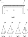
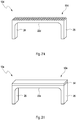
- FIGS. 2d, 2e . 2f, 2g, 2h, 2i . 2y . 2k, 2l show possible variants of the embodiment of the carrier system 2, in particular a connector 10 included therein.
- This carrier system 2 comprises two carriers 4, which are connected to one another via the first embodiment of the connection system 8 according to the invention, this connection system 8 having as components a first and a second connector 10, wherein the second connector 10 only in the FIGS. 2b and 2c is shown in sectional view.
- each carrier 4 has a carrier body 12 which is delimited by two secondary carrier bodies 14.
- both carriers 4 have a double-T-shaped profile or I-shaped profile.
- each connector 10 has a connector body 22 which is bounded by two sub-connector bodies 26, respectively.
- the two connectors 10 each have a U-shaped profile.
- Each carrier 4 has a major axis and each connector 10 has a connection axis, wherein the major axes of the carriers 4 and the connection axes of the connectors 10 are projected upon connection to an axis which in FIG. 2a is indicated by a dashed line 30.
- each connector 10 has two rows of connector holes 32, which are arranged side by side parallel to connecting axes of the connector body 22 here.
- Carrier holes 34 are provided as further components of the connection system 8, wherein here each carrier 4 has two rows of carrier holes 34, wherein in each case one row of carrier holes 34 are arranged parallel to the main axis of a respective carrier 4 next to each other.
- For the carrier holes 34 is provided that they are parallel to their respective major axis longer than the round connector holes 32 here parallel to the connection axis of the respective connector 10.
- the carriers 4 have here circular or round carrier holes 34, which are guided by the carrier body 12 and pass through it.
- a first further variant of the carrier holes is formed elliptical, wherein a large half-axis of a respective carrier hole parallel to the main axis of the carrier is longer than a radius of a connector hole 32.
- a small half-axis of this variant of carrier holes also perpendicular to the main axis of the carrier wider than the radius of each connector hole 32.
- the second further variant of carrier holes is parallel to the main axis elongated or formed as a slot, such a variant of a carrier hole parallel to the major axis is longer than the radius of a respective connector hole 32.
- first front planar outer surfaces of the carrier body 12 of both carriers 4 of the connector body 22 of the first connector 10 is arranged with an uneven textured outer surface, wherein a first group of connector holes 32 each row of carrier holes 34 is assigned to a respective row of the first carrier 4.
- a second group of a respective row of connector holes 32 of the first connector 10 is associated with respective carrier holes 34 of a respective row of carrier holes 34 of the second carrier 4.
- the connector body 22 of the second connector 10 is arranged with an uneven textured outer surface on the second flat outer surfaces of the carrier body 12 of both carriers 4, wherein each one group and thus only a portion of a respective row of connector holes 32 of the second connector 10 each carrier holes 34 along a respective row of a respective carrier 4 is assigned.
- two connector holes 32 namely, a connector hole 32 of the first connector 10 and a connector hole 32 of the second connector 10 are thus respectively assigned to a support hole 34.
- a connector hole 32 of the first connector 10 is inside the connector body 22 with the uneven outer surface on the front flat outer surface of a respective support body 12 and a second connector hole 32 within the connector body 22 of the second connector 20 of the connector body 22 with the uneven outer surface on the rear planar outer surface of the respective carrier body 12 is arranged.
- the support hole 34 is arranged in alignment with the connector holes 32 associated therewith.
- a pin or a bolt of a fastener 44 formed here as a lock bolt first by a connector hole 32 of a first of the two connector 10, then by a support hole 34 of a respective support 4 and further by a connector hole 32nd the other of the two connectors 10 is guided and fastened, which is in Figure 2c is indicated.
- the connector body 22 of both connectors 10 are formed perpendicular to their respective connecting axes shorter than the carrier body 12 of the two carriers 4 perpendicular to their respective major axis.
- the secondary connector bodies 26 are spaced from the secondary carrier bodies 14.
- FIGS. 2d, 2e . 2f . 2k, 2l show, different variants of connectors 10a, 10b, 10c, 10d, 10e are provided for the connection system 8 and thus for the support system 2, wherein these variants of the connectors 10a, 10b, 10c, 10d, 10e differ in detail by different structures , wherein the outer surfaces 50a, 50b, 50c, 50d, 50e of the connector bodies 22a, 22b, 22c, 22d, 22e are unevenly structured or have uneven structures, in contrast to flat or smooth outer surfaces of the carrier bodies 12, wherein these unevenly structured outer surfaces 50a , 50b, 50c, 50d, 50e are arranged on the flat or on the smooth outer surfaces of the connector body 22 of the carrier 4.
- the outer surface 50a of the connector body 22a of the connector 10a has a tooth-shaped or zigzag-shaped profile in a first spatial direction, eg, longitudinal direction, or in a second spatial direction, eg, transverse direction.
- the two mutually perpendicular spatial directions of the outer surface 50a each are oriented according to requirement and / or an expected load of the carrier system 2 relative to the main axes and the connection axis or are.
- the outer surface 50b of the connector body 22b has a wave-shaped profile which is oriented in the longitudinal direction or transverse direction to the main axis of the carrier 5 or to the connection axis of the connector 10b, as required and / or loaded.
- the profiles along a first line are parallel to one of the two spatial directions, i. H. either parallel to the longitudinal direction or parallel to the transverse direction, regularly repeating periodically, d. H. zigzag or undulating, formed and straight along a second line perpendicular thereto.
- the outer surface 50c of the connector body 22c has a formed of many small pyramid profile, which is formed depending on the definition in two mutually perpendicular spatial directions each periodically repeating.
- Possible variants of such pyramids 52a, 52b, 52c, 52d on the outer surface 50c are in the Figures 2g, 2h, 2i, 2j indicated. It is provided that bases of such pyramids 52a, 52b, 52c, 52d are formed n-angular.
- a first variant of a pyramid 52a has a square base ( Figure 2g )
- a second variant of the pyramid 52b a rectangular base ( FIG. 2h )
- a third variant of the pyramid 52c has a regular triangular base ( FIG. 2i )
- a fourth variant of the pyramid 52d a hexagonal base ( FIG. 2j ) on.
- the surface 50d of the connector body 22d of the connector 10d has a wave-shaped profile, which in each case in a first and in a second spatial direction is wavy, periodically repeating, wherein the two spatial directions are oriented perpendicular to each other. Accordingly, a structure of this profile in the two spatial directions, ie in the longitudinal direction and in the transverse direction, alternately concave and convex and has a curved uneven textured outer surface 50d. Depending on the definition, the profile has a multiplicity of convex mountains, with one such rounded mountain in each case being separated by a rounded concave valley from an adjacent mountain.
- Pyramids 52a, 52b, 52c, 52d of the third Variations of the surface 50c or mountains of the fourth variant of the outer surface 50d are arranged, for example, like honeycombs relative to one another, wherein the unevenly structured outer surfaces 50c, 50d are profiled and / or structured similarly to soundproof walls.
- each unevenly structured outer surfaces 50a, 50b, 50c, 50d are, for example, by plasma spraying, flame spraying, high-speed flame spraying, detonation spraying, cold gas spraying, arc spraying, plasma powder build-up welding and / or laser spraying the connector body 22a, 22b, 22c, 22d produced.
- a fifth variant of an outer surface 50e is formed as a coating 54 on the connector body 22e.
- additional material is introduced or applied, inserted or placed and / or glued or placed.
- the material for the coating 54 as a composite material, for example. Fiber-reinforced or glass fiber reinforced plastic, designed as a wire mesh, honeycomb or closing, it is possible that such a coating is also elastically deformable and thus yielding under the action of a force.
- outer surfaces 50a, 50b, 50c, 50d, 50e of connectors 10a, 10b, 10c, 10d, 10e By structuring outer surfaces 50a, 50b, 50c, 50d, 50e of connectors 10a, 10b, 10c, 10d, 10e, on the other hand, it is possible to cause stiction in contact surfaces or friction surfaces between a respective connector 10a, 10b, 10c, 10d, 10e and a respective carrier 4 to increase.
- the outer surface 50a, 50b, 50c, 50d, 50e is to be structured and / or supplied by a further production method profile, wherein a roughness and thus the static friction coefficient of the outer surface 50a, 50b, 50c, 50d, 50e is increased.
- each support 4 is further provided by a biasing force with which each support 4 is to be arranged between two connectors 10, for example, by a toothing or wave-shaped profiling of the outer surface 50a, 50b, 50c, 50d, 50e or a corresponding contact surface to increase and thereby to transfer higher forces between each two connectors 10 and each one arranged therebetween carrier 4, it may be possible to reduce a number of required connectors 10a, 10b, 10c, 10d, 10e and / or their size.
- the unevenly structured and / or profiled outer surfaces 50a, 50b, 50c, 50d, 50e can be produced in different production methods. These are cutting or machining processes, forming, rolling and / or rolling, stamping, cold working, laser cutting, firing or plasma cutting.
- the outer surface 50e to be provided via the coating 54 can be provided, for example, by inserting and / or gluing in a wire mesh.
- the second embodiment of the carrier system 150 according to the invention is in the FIGS. 3a, 3b shown schematically in different operating situations.
- this embodiment of the carrier system 150 comprises two carriers 104a, 104b, which are connected here via two connectors 110.
- the two connectors 110 with their connector bodies 122, through which the circular connector holes 132 are guided here, are formed as components of the third embodiment of the connection system 152 according to the invention.
- each connector body 122 of each connector 110 has an uneven structure, as exemplified by FIG. 2 is described.
- circular support holes 134a, 134b which pass through the support body 112a, 112b of the two carriers 104a, 104b, also as components of the embodiment of the connection system 152 trained.
- outer surfaces of carrier bodies 112a, 112b of the carriers 104a, 104b are flat or smooth.
- the connector holes 132 of the two connectors 110 are arranged along two rows parallel to the connection axis of each connector 110.
- the round carrier holes 134a, 134b are also arranged side by side in two rows parallel to the main axis of a respective carrier 104a, 104b.
- the connector holes 132 parallel to the connection axes of the connectors 110 are shorter than the support holes 134a, 134b parallel to the major axes.
- each connector 110 has two rows of connector holes 132, each of these two rows comprising six connector holes 132 arranged side by side along the row.
- each carrier 104a, 104b comprises two rows of carrier holes 134a, 134b, each with three carrier holes 134a, 134b.
- a group of three connector holes 132 of a row of connector holes 132 is assigned to a group of carrier holes 134a, 134b of a respective row, respectively a first group of a row of connector holes 132, namely half the connector holes 132 of the respective row, here three carrier holes 134a, 134b respectively associated with a carrier 104a, 104b, wherein each half of connector holes 132 of a respective row carrier holes 134a, 134b each one row of a carrier 104a, 104b assigned.
- an outer surface of a carrier body 112a, 112b which has the uneven structure, is arranged on both front flat outer surfaces and on the rear outer surfaces of the two carrier bodies 112a, 112b.
- FIG. 3a It is also in FIG. 3a indicated by a first double arrow 210, a normal force acting in the longitudinal direction of the carrier 102a, 102b.
- a curved arrow 212 indicates a bending moment between the two beams 104a, 104b.
- a second double arrow 214 are here Shearing transverse forces between the two carriers 104a, 104b indicated.
- the two supports 104a, 104b which are connected via the connectors 10a, to be parallel to one another ( FIG. 4a ) or at an obtuse angle ( FIG. 4b ) relative to each other.
- a connector hole 132 may reciprocate relative to a carrier hole 134a, 134b to the common major axis of a respective carrier 104a, 104b.
- the two are already out FIG. 3 known carrier 104a, 104b connected to each other via a third embodiment of the connection system 172 according to the invention here having at least one connector 174
- the connector body 176 is divided into a first portion 178a and a second portion 178b, wherein here for each section 178a, 178b, a connection axis is provided, wherein the connecting axes of both sections 178a, 178b are oriented at an obtuse angle to each other here, which is why the connector body 176 of the at least one connector 174 here has an obtuse-angled bend, wherein it is optionally provided that the two sections 178a, 178b via a optional shock or top plate 180 are connected together.
- an outer surface of the Connector body 176 of the at least one connector 174 on an uneven structure.
- first portion 178a of the connector body 176 has two rows of three connector holes 132 each, which are arranged parallel to the first connection axis of the at least one connector 174.
- second portion 178b of the connector body 176 of the at least one connector 174 has two rows each having three circular connector holes 132 oriented parallel to the second connection axis of the at least one connector 174.
- the two rows of carrier holes 134a which are oriented parallel to the main axis of the first carrier 104a, are assigned to the two rows of connector holes 132 of the first portion 178a of the connector 174. It is also provided here that the carrier holes 134a have larger radii than the connector holes 132 and thus are at least parallel to the main axis of the first carrier 104a longer than the connector holes 132 parallel to the first connection axis.
- the connector holes 132 of the two rows of connector holes 132 of the second portion 178b of the carrier 174 are associated with the two rows of carrier holes 134b of the second connector 104b, which connector holes 132 have smaller radii than the carrier holes 134b.
- both sections 178a, 178b which have the uneven structure, are arranged on the flat or smooth outer surfaces of the two carrier bodies 112a, 112b.
- the embodiment of the carrier system 170 shown schematically in FIG. 5 is suitable, for example, for a ridge impact in the case of a hall frame if it is provided that the two carriers 104a, 104b are oriented at the intended angle to each other, this angle in turn being definable by those angles in which the two connection axes of the two sections 178a, 178b of the at least one connector 174 are oriented relative to one another.
Landscapes
- Engineering & Computer Science (AREA)
- Architecture (AREA)
- Physics & Mathematics (AREA)
- Electromagnetism (AREA)
- Civil Engineering (AREA)
- Structural Engineering (AREA)
- Connection Of Plates (AREA)
Abstract
Description
- Die Erfindung betrifft ein Verbindungssystem zum Verbinden von zwei Trägern, ein Trägersystem und ein Verfahren zum Verbinden von zwei Trägern.
- Zwei Bauteile können durch unterschiedliche Maßnahmen miteinander verbunden werden. So ist es bspw. möglich, ein Verbindungselement zu verwenden, das einerseits mit einem ersten Bauteil und andererseits mit einem zweiten Bauteil verbunden wird, so dass die beiden Bauteile über das Verbindungselement miteinander indirekt verbunden werden.
- Die Druckschrift
DE 93 08 783 U1 zeigt einen lagestabilen Eisenbahnoberbau. Ein Gehäuse zur Aufnahme von Klimageräten ist aus der DruckschriftDE 20 2012 010 569 U1 bekannt. Eine kraftschlüssige Verbindung von Bauelementen ist in der DruckschriftDE 2 700 089 A1 beschrieben. Die DruckschriftEP 0 133 565 B1 zeigt ein Verbundprofil. - Vor diesem Hintergrund war es eine Aufgabe, zwei Träger flexibel und stabil zu verbinden.
- Diese Aufgabe wird mit einem Verbindungssystem, einem Trägersystem und einem Verfahren mit den Merkmalen der unabhängigen Patentansprüche gelöst. Ausgestaltungen des Verbindungssystems, des Trägersystems und des Verfahrens gehen aus den abhängigen Patentansprüchen und der Beschreibung hervor.
- Das erfindungsgemäße Verbindungssystem ist zum Verbinden von zwei Trägern ausgebildet, die jeweils einen flachen Trägerkörper aufweisen, der durch mindestens eine Endkante begrenzt ist und mindestens ein Trägerloch, bspw. mehrere Trägerlöcher, aufweist. Dabei ist für jeden Träger eine Hauptachse vorgesehen, die unter einem Winkel, bspw. senkrecht zu der mindestens einen Endkante orientiert ist. Das Verbindungssystem weist mindestens einen Verbinder mit einem flachen Verbinderkörper und mindestens einer Verbindungsachse auf, wobei der Verbinderkörper von mehreren kreisförmigen bzw. runden Verbinderlöchern, durchsetzt ist, wobei mindestens eine Außenfläche des mindestens einen Verbinderkörpers eine unebene Struktur, bspw. ein Profil und/oder eine Beschichtung, aufweist. Das Verbindungssystem weist mehrere Befestigungselemente auf. Die beiden Träger sind bspw. koaxial zu ihren Hauptachsen mit einander zugewandten Endkanten nebeneinander anordenbar, wobei die mindestens eine Außenfläche mit der unebenen Struktur des mindestens einen Verbinderkörpers des mindestens einen Verbinders auf jeweils mindestens einer Außenfläche der Trägerkörper beider Träger anordenbar bzw. anzuordnen ist, wobei ein erstes Verbinderloch des mindestens einen Verbinders, bspw. eine erste Gruppe aus bzw. mit dem mindestens einen Verbinderloch, dem mindestens einen Trägerloch eines ersten Trägers der beiden Träger und mindestens ein zweites Verbinderloch des mindestens einen Verbinders, bspw. eine zweite Gruppe aus bzw. mit dem mindestens einen Verbinderloch, dem mindestens einen Trägerloch eines zweiten Trägers der beiden Träger zuordenbar bzw. zuzuordnen ist, so dass durch mindestens ein Verbinderloch des mindestens einen Verbinders und ein zugeordnetes Trägerloch des jeweiligen Trägers jeweils ein Befestigungselement führbar bzw. zu führen ist, wodurch der mindestens eine Verbinder über jeweils mindestens ein Befestigungselement mit jeweils einem Träger zu verbinden ist.
- Die mindestens eine Außenfläche des mindestens einen Verbinderkörpers des mindestens einen Verbinders mit der unebenen Struktur weist Unregelmäßigkeiten an ihrer Oberfläche, wie bspw. Erhebungen und/oder Vertiefungen, auf. Im Unterschied hierzu weisen die Außenflächen der Trägerkörper beider Träger in der Regel eine ebene und/oder glatte Struktur auf.
- In Ausgestaltung weist die unebene Struktur der mindestens einen Außenfläche eines Trägers ein Profil auf, das in zumindest einer Raumrichtung uneben strukturiert ist. Es ist denkbar, dass das Profil in der zumindest einen Raumrichtung eine periodische, d. h. sich regelmäßig wiederholende unebene Struktur aufweist.
- Das sich bspw. in der mindestens einen Raumrichtung periodisch wiederholende Profil ist in der mindestens einen Raumrichtung bspw. zickzackförmig oder wellenförmig, bspw. sinusförmig, ausgebildet. Falls sich das Profil lediglich in einer ersten Raumrichtung periodisch wiederholt, ist es nur in dieser einen Raumrichtung profiliert bzw. uneben, jedoch in einer zu der ersten Raumrichtung senkrechten zweiten Raumrichtung gerade. Das bedeutet, dass sich das Profil entlang einer Linie parallel zu der ersten Raumrichtung periodisch ändert, während das Profil entlang einer Linie parallel zu der zweiten Raumrichtung gerade ist. Falls das Profil bspw. zickzack- oder wellenförmig ist, weist es eine Vielzahl aufeinanderfolgender Berge und Täler auf.
- Falls das Profil entlang beider zueinander senkrechter Raumrichtungen jeweils wiederholend periodisch ausgebildet ist, weist es für den Fall, dass es in beiden Raumrichtungen zickzackförmig ist, eine Vielzahl an Pyramiden auf, die in einem Feld bzw. einer Matrix angeordnet sind. Falls das Profil in beiden Raumrichtungen wellenförmig ist, weist es je nach Definition ein Feld mit einer Vielzahl abgerundeter Pyramiden auf. Demnach ändert sich das Profil sowohl entlang einer ersten Linie parallel zu der ersten Raumrichtung als auch entlang einer zweiten Linie parallel zu der zweiten Raumrichtung jeweils periodisch wiederholend. In der Regel ist die erste Raumrichtung als Querrichtung und die zweite Raumrichtung als Längsrichtung definierbar.
- Alternativ oder ergänzend ist die unebene Struktur der mindestens einen Außenfläche durch eine bspw. elastisch verformbare Beschichtung gebildet, die auf dem Verbinderkörper angeordnet ist. Dabei ist es möglich, dass die Beschichtung das Profil aufweist, das in der mindestens einen Raumrichtung die sich periodisch wiederholende Struktur aufweist.
- Das Verbindungssystem weist üblicherweise zwei Verbinder auf, wobei auf ersten ebenen bzw. glatten Außenflächen der Trägerkörper beider Träger ein erster Verbinder anordenbar bzw. anzuordnen ist, und wobei auf zweiten ebenen bzw. glatten, in der Regel den ersten Außenflächen gegenüberliegenden bzw. abgewandten Außenflächen der Trägerkörper beider Träger, ein zweiter Verbinder anordenbar bzw. anzuordnen ist.
- In weiterer Ausgestaltung sind die Verbinderlöcher des mindestens einen Verbinders kreisförmig bzw. rund und bspw. entlang mindestens einer Reihe parallel zu der mindestens einen Verbindungsachse angeordnet, wobei mehrere Trägerlöcher eines Trägerkörpers jeweils eines Trägers, bspw. entlang mindestens einer Reihe, parallel zu der Hauptachse des Trägers angeordnet sind. Außerdem ist jeweils ein Trägerloch parallel zu der Hauptachse länger als jeweils ein Verbinderloch parallel zu der mindestens einen Verbindungsachse und mindestens so breit wie das jeweilige Verbinderloch senkrecht zu der mindestens einen Verbindungsachse. Eine erste Gruppe aus Verbinderlöchern der mindestens einen Reihe aus Verbinderlöchern ist den Trägerlöchern der mindestens einen Reihe aus Trägerlöchern eines ersten Trägers der beiden Träger und eine zweite Gruppe aus Verbinderlöchern der mindestens einen Reihe aus Verbinderlöchern den Trägerlöchern der mindestens einen Reihe aus Trägerlöchern eines zweiten Trägers der beiden Träger zuordenbar bzw. zuzuordnen, wobei jeweils durch mindestens ein Verbinderloch des mindestens einen Verbinders und ein zugeordnetes Trägerloch des jeweiligen Trägers ein Befestigungselement führbar bzw. zu führen ist, wodurch der mindestens eine Verbinder über jeweils ein Befestigungselement mit jeweils einem Träger zu verbinden ist bzw. verbindbar ist.
- Dabei ist es möglich, dass der mindestens eine Verbinder mindestens zwei zueinander parallel angeordnete Reihen Verbinderlöcher und jeweils ein Träger mindestens eine Reihe, bspw. zwei zueinander parallel angeordnete Reihen, Trägerlöcher aufweist.
- Üblicherweise weist jede Reihe und/oder Gruppe Verbinderlöcher das mindestens eine Verbinderloch auf. Entsprechend weist jede Reihe und/oder Gruppe Trägerlöcher das mindestens eine Trägerloch auf.
- Weiterhin ist mindestens ein Trägerloch als Langloch ausgebildet, wobei dessen Längsachse parallel zu der Hauptachse des Trägers orientiert und länger als das jeweilige dem Trägerloch beim Verbinden der beiden Träger zugeordnete Verbinderloch ist. Außerdem ist es möglich, dass mindestens ein Trägerloch ellipsenförmig ausgebildet ist, wobei jeweils eine große Halbachse bzw. Längsachse des Trägerlochs parallel zu der Hauptachse des Trägers orientiert und länger als das jeweilige dem Trägerloch beim Verbinden der beiden Träger zugeordnete Verbinderloch parallel zu der Verbindungsachse ist, und wobei jeweils eine kleine Halbachse bzw. Querachse des Trägerlochs senkrecht zu der Hauptachse des Trägers orientiert und mindestens so breit wie das jeweilige Verbinderloch ist.
- Durch Vorsehen der unebenen Struktur auf mindestens einer Außenfläche des mindestens einen Verbinderkörpers wird eine Rauigkeit der Reiboberfläche zwischen dem mindestens einen Verbinderkörper und den Trägerköpern erhöht. Dabei ist es möglich, dass der mindestens eine Verbinder U-förmig, bspw. als U-förmiges Eisen, Flacheisen oder Winkeleisen mit mindestens einer Außenfläche mit unebener Struktur ausgebildet ist. Mindestens ein U-förmig ausgebildeter Verbinder ist bspw. für eine biegefeste Verbindung von zwei Trägern vorgesehen, da hier eine zu der mindestens einen Verbindungsachse symmetrische und/oder gleiche Steifigkeit erreichbar ist. Falls nur Normalkräfte parallel zu der Hauptachse oder Querkräfte senkrecht zu den Hauptachsen der Träger zu übertragen sind, sind unterschiedliche voranstehend genannte Formen des mindestens einen Verbinders möglich.
- Für eine Ausgestaltung des mindestens einen Verbinders sind unterschiedliche Varianten denkbar. In der Regel weist der mindestens eine Verbinder gemäß einer ersten Variante einen geraden, bspw. quaderförmigen Verbinderkörper mit einer einzigen Verbindungsachse auf, entlang der die mindestens eine Reihe an Löchern angeordnet ist. In einer alternativen zweiten Variante ist es jedoch auch möglich, dass der Verbinderkörper des mindestens einen Verbinders bspw. einen Knick aufweist, wobei zwei Abschnitte des Verbinderkörpers des mindestens einen Verbinders jeweils eine Verbindungsachse aufweisen, wobei die beiden Verbindungsachsen der beiden Abschnitte bspw. unter einem stumpfen Winkel relativ zueinander orientiert sind. Bei dieser zweiten Variante ergibt sich, dass mindestens eine erste Reihe an Verbinderlöchern innerhalb des ersten Abschnitts des Verbinderkörpers parallel zu der ersten Verbindungsachse und mindestens eine zweite Reihe an Verbinderlöchern innerhalb des zweiten Abschnitts des Verbinderkörpers parallel zu der zweiten Verbindungsachse orientiert ist. Weiterhin ist bei dieser zweiten Variante vorgesehen, dass die erste Gruppe Verbinderlöcher der mindestens einen ersten Reihe, die parallel zu der ersten Verbindungsachse orientiert ist, den Trägerlöchern der mindestens einen Reihe Trägerlöcher des ersten Trägers und die zweite Gruppe der Verbinderlöcher der mindestens einen zweiten Reihe Verbinderlöcher, die parallel zu der zweiten Verbindungsachse orientiert ist, den Trägerlöchern der mindestens einen Reihe Trägerlöcher des zweiten Trägers zuordenbar bzw. zuzuordnen ist.
- Bei der ersten Variante des mindestens einen Verbinders ist vorgesehen, dass die beiden Hauptachsen der beiden Träger relativ zueinander unter einem Winkel anordenbar sind. Dabei ist es möglich, dass dieser Winkel bspw. 0° bzw. 180° entspricht, wobei die Hauptachsen der beiden Träger in diesem Fall zueinander parallel bzw. koaxial anordenbar sind. Aufgrund der unterschiedlichen Größen der Trägerlöcher und der Verbinderlöcher ist es möglich, dass der Winkel zwischen den beiden Hauptachsen der beiden Träger um einige Winkelgrade, bspw. eine einstellige Anzahl an Winkelgraden, variierbar ist, wobei die Hauptachsen der beiden Träger auch unter einem stumpfen Winkel nebeneinander anordenbar sind.
- Bei der zweiten Variante des mindestens einen Verbinders, wenn dessen beide Verbindungsachsen entlang seiner beiden Abschnitte unter dem Winkel zueinander orientiert sind, sind die Hauptachsen der beiden Träger entsprechend dem Winkel zwischen den beiden Verbindungsachsen relativ zueinander zu orientieren, wobei es aufgrund der unterschiedlichen Größen der Verbinderlöcher und der Trägerlöcher auch in diesem Fall möglich ist, dass der aufgrund einer relativen Orientierung der beiden Verbindungsachsen des mindestens einen Verbinders vorgesehene Winkel ebenfalls um einige Winkelgrade variiert wird.
- Mit dem Verbindungssystem ist zwischen den beiden Trägern eine biegesteife Reibverbindung, bspw. Reibeisenverbindung, bereitstellbar. Aufgrund des Umstands, dass die Trägerlöcher zumindest parallel zu den Hauptachsen der Träger größer als die Verbinderlöcher der mindestens einen Reihe an Verbinderlöchern des mindestens einen Verbinders sind, erfolgt eine Übertragung von Kräften zwischen den beiden Trägern nicht wie gewöhnlich über eine Querkraftbelastung der bspw. als Schrauben ausgebildeten Befestigungselemente über eine Leibung der Trägerlöcher, sondern über eine Reibkraft in einer Kontaktfläche zwischen jeweils einem Träger und dem mindestens einen Verbinder. Dabei resultiert die Reibkraft aus einer Vorspannung der Befestigungselemente. Aufgrund der unterschiedlichen Größen der Verbinderlöcher und der Trägerlöcher ist es möglich, die beiden zu verbindenden Träger relativ zueinander zu justieren und etwaige Toleranzen auszugleichen.
- Weiterhin ist vorgesehen, dass jeder Träger eine Reihe oder mehrere Reihen an Trägerlöchern aufweist, wobei eine Anzahl an Reihen je nach Anwendung wählbar ist. Außerdem ist eine Anzahl an Trägerlöchern einer jeweiligen Reihe auch ebenfalls je nach Anwendungsfall bzw. Erfordernis wählbar. Entsprechend weist der mindestens eine Verbinder entlang seiner mindestens einen Verbindungsachse eine entsprechende Anzahl an Reihen von Verbinderlöchern wie jener Träger auf, dem dieser zuzuordnen ist. Entsprechend einer Anzahl der Trägerlöcher einer jeweiligen Reihe des jeweiligen Verbinders ist auch eine Anzahl einer jeweiligen Gruppe an Verbinderlöchern der mindestens einen Reihe zu wählen.
- In Ausgestaltung sind die Hauptachse und die Endkante eines jeweiligen Trägers unter einem Winkel, bspw. einem Winkel von 90°, zueinander bspw. senkrecht orientiert.
- In Ausgestaltung weist der mindestens eine Verbinder mindestens zwei bzw. mehrere zueinander sowie zu der mindestens einen Verbindungsachse parallel angeordnete Verbinderlöcher und jeweils ein Träger mindestens zwei bzw. mehrere zueinander sowie zu seiner Hauptachse parallel angeordnete Reihen Trägerlöcher auf. Üblicherweise weist der mindestens eine Träger mindestens eine derartige Reihe, d. h. eine oder mehrere Reihen, an Verbinderlöchern und jeder Träger eine entsprechende Anzahl mindestens einer Reihe an Trägerlöchern auf, wobei die Anzahl an Verbinderlöchern und Trägerlöchern einer jeweiligen Reihe variierbar ist.
- Das erfindungsgemäße Trägersystem weist eine Ausführungsform des Verbindungssystems und zwei Träger auf, die mit dem bspw. über das Verbindungssystem miteinander verbunden sind bzw. werden.
- Dabei ist es möglich, dass ein Trägerkörper jedes Trägers parallel zu der Hauptachse des jeweiligen Trägers breiter als der Verbinderkörper des mindestens einen Verbinders parallel zu der mindestens einen Verbindungsachse ist.
- Das erfindungsgemäße Verfahren ist zum Verbinden von zwei Trägern vorgesehen, die jeweils einen flachen Trägerkörper aufweisen, der durch mindestens eine Endkante begrenzt ist und mindestens ein Trägerloch, bspw. mehrere Trägerlöcher, aufweist, wobei für jeden Träger eine Hauptachse vorgesehen ist, die senkrecht zu der mindestens einen Endkante orientiert ist, wobei das Verbindungssystem mindestens einen Verbinder mit einem flachen Verbinderkörper und mindestens einer Verbindungsachse aufweist, wobei der Verbinderkörper von mindestens einem Verbinderloch, bspw. mehreren kreisförmigen bzw. runden Verbinderlöchern, durchsetzt ist, wobei mindestens eine Außenfläche des mindestens einen Verbinderkörpers eine unebene Struktur aufweist. Das Verbindungssystem weist weiterhin mehrere Befestigungselemente auf. Bei dem Verfahren werden die beiden Träger mit einander zugewandten Endkanten nebeneinander angeordnet. Die mindestens eine Außenfläche mit der unebenen Struktur des mindestens einen Verbinderkörpers des mindestens einen Verbinders wird auf jeweils mindestens einer bspw. ebenen und/oder glatten Außenfläche der Trägerkörper beider Träger angeordnet, wobei mindestens ein erstes Verbinderloch, bspw. von einer ersten Gruppe aus bzw. mit mindestens einem ersten Verbinderloch des mindestens einen Verbinders, mindestens einem Trägerloch eines ersten Trägers der beiden Träger und mindestens ein zweites Verbinderloch, bspw. von einer zweiten Gruppe aus bzw. mit mindestens einem zweiten Verbinderloch des mindestens einen Verbinders, mindestens einem Trägerloch eines zweiten Trägers der beiden Träger zugeordnet wird, sodass durch mindestens ein Verbinderloch des mindestens einen Verbinders und ein zugeordnetes Trägerloch des jeweiligen Trägers jeweils ein Befestigungselement geführt wird, wodurch der mindestens eine Verbinder über jeweils mindestens ein Befestigungselement mit jeweils einem Träger verbunden wird.
- In möglicher Ausgestaltung ist eine Hauptachse jeweils eines Trägers senkrecht zu seiner Endkante orientiert. Außerdem ist es möglich, dass die mindestens eine Verbindungsachse des mindestens einen Verbinders parallel zu der Hauptachse eines jeweiligen Trägers angeordnet wird.
- Aufgrund der unterschiedlichen Größen der Trägerlöcher einerseits und der Verbinderlöcher andererseits ist beim Verbinden des mindestens einen Verbinders mit den beiden Trägern parallel zu den Hauptachsen ein Toleranzausgleich möglich. Weiterhin ist es ebenfalls möglich, dass die Hauptachsen der beiden Träger bei der ersten Variante des mindestens einen Verbinders, wenn dieser lediglich eine Verbindungsachse aufweist, unter einem um einige Winkelgrade variierbaren Winkel von bspw. 0° bzw. 180° und demnach parallel bzw. koaxial zueinander sowie ggf. unter einem stumpfen Winkel relativ zueinander angeordnet werden.
- Bei der zweiten Variante des mindestens einen Trägers, wenn dieser zwei Verbindungsachsen aufweist, die unter einem Winkel relativ zueinander orientiert sind, werden die Hauptachsen der beiden Träger weitgehend dem vorgesehenen Winkel entsprechend relativ zueinander orientiert, wobei hierbei aufgrund der unterschiedlichen Größen der Trägerlöcher sowie der Verbinderlöcher ebenfalls eine Variation von einigen Winkelgraden möglich ist, um somit bspw. etwaige Toleranzen auszugleichen.
- Üblicherweise ist vorgesehen, dass die beiden Träger über zwei Verbinder miteinander verbunden werden. Dabei ist vorgesehen, dass beide Verbinder jeweils mindestens eine Reihe, bspw. mindestens zwei Reihen mit dem mindestens einen Verbinderloch, und jeder Träger ebenfalls mindestens eine Reihe, bspw. mindestens zwei Reihen mit Trägerlöchern, aufweist, wobei die Trägerlöcher zumindest parallel zu der Hauptachse des Trägers länger als das mindestens eine zuzuordnenden Verbinderloch parallel zu der mindestens einen Verbindungsachse ist. Zum Verbinden werden die Hauptachsen beider Träger unter dem Winkel von bspw. 0° bzw. 180°, d. h. parallel zueinander mit einer Abweichung um wenige Winkelgrade nebeneinander angeordnet, wobei es möglich ist, dass sich die Endkanten der Träger berühren oder einen geringen Abstand zueinander aufweisen, wobei ein maximaler Abstand zwischen den Endkanten beim Verbinden der beiden Träger mittels der Verbinder abhängig von einem Unterschied einer Länge jeweils eines Trägerlochs parallel zu der Hauptachse zu einer Länge jeweils eines Verbinderlochs parallel zu der Verbindungsachse ist. Weiterhin wird der erste Verbinder auf vorderen, bspw. ebenen Außenflächen bzw. Vorderseiten der Trägerkörper angeordnet, wohingegen ein zweiter Verbinder auf hinteren bzw. rückseitigen, bspw. ebenen Außenflächen bzw. Rückseiten der Trägerkörper angeordnet wird. Dabei wird jeweils einem Trägerloch ein Verbinderloch des ersten Verbinders auf einer vorderen Außenseite sowie ein Verbinderloch des zweiten Verbinders auf der anderen Außenfläche bzw. Rückseite des Trägerkörpers zugeordnet. Das Befestigungselement wird sodann durch eines der Verbinderlöcher, das Trägerloch und das andere Verbinderloch geführt, wobei der Träger über dieses mindestens eine Befestigungselement mit beiden Verbindern verbunden wird.
- In Ausgestaltung weist jeder Träger neben dem Trägerkörper zwei Nebenträgerkörper auf. Dabei ist jeweils ein Nebenträgerkörper an einer Außenseite eines Trägerkörpers angeordnet, die parallel zu der Hauptachse des jeweiligen Trägerkörpers orientiert ist. Dabei sind die beiden in der Regel quaderförmigen Nebenträgerkörper senkrecht zu dem Trägerkörper orientiert, wobei der Trägerkörper die beiden Nebenträgerköper jeweils senkrecht, ungefähr entlang einer Mittelachse eines jeweiligen Nebenträgerkörpers schneidet. Demnach ist jeweils ein Träger als sogenannter Doppel-T-Träger ausgebildet und/oder zu bezeichnen. Und weist demnach ein doppel-T-förmiges Profil auf. Dagegen weist der mindesten eine Verbinder ein U-förmiges Profil auf und ist demnach bspw. als U-Eisen ausgebildet und/oder zu bezeichnen. Dabei weist der mindestens eine Verbinder neben dem bereits beschriebenen Verbinderkörper auch Nebenverbinderkörper auf, die an Außenseiten des Verbinderkörpers parallel zu der mindestens einen Verbindungsachse angeordnet sind und senkrecht vom Verbinderkörper abstehen und beim Verbinden des Verbinders mit einem jeweiligen Träger von dem jeweiligen Träger wegweisen.
- Somit bilden die Nebenträgerkörper eines jeweiligen Trägerkörpers eines Trägers Flansche des Trägers. Entsprechend bilden die Nebenverbinderkörper Flansche des mindestens einen Verbinders. Da der Verbinderkörper des mindestens einen Verbinders schmaler als der Trägerkörper jedes Trägers ist, ergibt sich, dass bei dem abschließend durch das Verfahren verbundene Trägersystem jeweils ein Nebenverbinderkörper von einem Nebenträgerkörper beabstandet ist, und dass somit zwischen jeweils einem Nebenverbinderkörper und einem Nebenträgerkörper keine Kontaktfläche vorgesehen und/oder erforderlich ist. Der mindestens eine Verbinder, der in Ausgestaltung das U-Profil, bspw. ein UPE-, UAP-, UPN-, Profil gemäß DIN 1026 aufweist, ist bspw. durch Abkanten eines Blechs herstellbar.
- Das vorgestellte Trägersystem ist unter Durchführung einer Ausführungsform des erfindungsgemäßen Verfahrens unter geringem Aufwand zu fertigen sowie einfach zu montieren, wobei aufgrund unterschiedlicher Größen der Trägerlöcher und der Verbinderlöcher bauübliche Toleranzen einfach ausgeglichen werden können.
- Mindestens ein zu verwendendes Befestigungselement weist einen Bolzen bzw. einen Stab auf, der durch das Trägerloch und das mindestens eine Verbinderloch zu führen bzw. zu schieben ist. Dabei ist es möglich, dass das mindestens eine Befestigungselement bspw. als Schraube oder Schließringbolzen ausgebildet ist. Über ein derartiges Befestigungselement wird eine garantierte Vorspannkraft zwischen dem Träger und dem mindestens einen Verbinder bereitgestellt. Außerdem ist eine derart bereitgestellte Verbindung wartungsfrei.
- Für die Träger und den mindestens einen Verbinder sind als Material unterschiedliche Metalle, bspw. Eisen und somit Materialen bzw. Erzeugnisse aus Stahl, aber auch andere Werkstoffe, bspw. Kunststoffe sowie auch Kombinationen aus Metallen und Kunststoffen möglich. Materialien aus Stahl sind z. B. Baustähle gemäß EN 10025 (S235JR G1, S355 J2 G3 usw.), Vergütungsstähle gemäß EN 10083, Einsatzstähle gemäß EN 10084, Werkzeugstähle gemäß DIN EN ISO 4957 und/oder korrosionsbeständige Stähle gemäß DIN EN 10028-7. Ergänzend werden weitere Normen, wie bspw. EN 10139, EN 10263, EN 573 T3, DIN EN 1561, DIN EN 1563, DIN EN 10293 und/oder EN 12449, berücksichtigt, wobei jeweils eine Version einer Norm aus dem Jahr 2017 und/oder zum Anmeldetag der Patentanmeldung zu berücksichtigen ist.
- Das mindestens eine Befestigungselement, das auch als Verbindungsmittel bezeichnet werden kann, ist vorspannbar und weist eine Sicherung auf, wodurch eine Reibkraftübertragung zwischen jeweils einem Träger und dem mindestens einen Verbinder gewährleistet wird. Das mindestens eine Befestigungselement ist als Schließringbolzen oder als HV (Handverschluss)-Schraube mit einer Sicherungsmaßnahme ausgebildet, wobei es sich bspw. um eine Keilsicherungsscheibe handelt.
- Weiterhin ist zu berücksichtigen, dass sich ein Schließringbolzen als das mindestens eine Befestigungselement im Laufe der Zeit aufgrund eines Kriechvorgangs nur geringfügig verlängert, wodurch eine erforderliche Vorspannkraft für eine Reibung zwischen dem Träger und dem mindestens einen Verbinder gewährleistet wird.
- Mit dem Verfahren ist es unter anderem möglich, zwei Träger in Richtung ihrer Hauptachsen und somit parallel zu ihren Längsachsen bzw. Längsrichtungen zu verbinden und somit durch den mindestens einen Verbinder ein verlängertes Trägersystem bereitzustellen, wobei die beiden einzelnen Träger aufgrund der unterschiedlichen Größen der Trägerlöcher und der Verbinderlöcher beim Verbinden bspw. parallel zu der mindestens einen Verbindungsachse des Verbinders und ggf. auch senkrecht zu der mindestens einen Verbindungsachse unter Bereitstellung eines Toleranzausgleichs verlängerbar sind. Durch Vorsehen der unterschiedlich großen Verbinderlöcher und Trägerlöcher ist zwischen den Endkanten der beiden Träger eine biegesteife Reibverbindung bereitstellbar. Weiterhin ist vorgesehen, dass ein Verbinderkörper des mindestens einen Verbinders dieselbe Steifigkeit wie der Trägerkörper des jeweiligen Trägers aufweist.
- Falls zum Verbinden der beiden Träger zwei Verbinder verwendet werden, wird jeweils ein Trägerloch eines Trägers zwischen zwei Verbinderlöchern beider Verbinder angeordnet und das Befestigungselement in der Regel an dem Verbinderkörper, bspw. dem Verbinderloch, des ersten Verbinders und dem Verbinderkörper, bspw. dem Verbinderloch, des zweiten Verbinders befestigt.
- Es versteht sich, dass die voranstehend genannten und die nachstehend noch zu erläuternden Merkmale nicht nur in der jeweils angegebenen Kombination, sondern auch in anderen Kombinationen oder in Alleinstellung verwendbar sind, ohne den Rahmen der vorliegenden Erfindung zu verlassen.
- Die Erfindung ist anhand von Ausführungsformen in den Zeichnungen schematisch dargestellt und wird unter Bezugnahme auf die Zeichnungen schematisch und ausführlich beschrieben.
-
Figur 1 zeigt in schematischer Darstellung eine aus dem Stand der Technik bekannte Anordnung. -
Figur 2 zeigt in schematischer Darstellung eine erste Ausführungsform des erfindungsgemäßen Trägersystems, das eine erste Ausführungsform des erfindungsgemäßen Verbindungssystems aufweist, wobei hier unterschiedliche Varianten von Trägern vorgesehen sind. -
Figur 3 zeigt in schematischer Darstellung eine zweite Ausführungsform des erfindungsgemäßen Trägersystems mit einer zweiten Ausführungsform des erfindungsgemäßen Verbindungssystems. -
Figur 4 zeigt in schematischer Darstellung eine dritte Ausführungsform des erfindungsgemäßen Trägersystems mit einer dritten Ausführungsform des erfindungsgemäßen Verbindungssystems. - Die Figuren werden zusammenhängend und übergreifend beschrieben. Gleichen Komponenten sind dieselben Bezugsziffern zugeordnet.
- Die aus dem Stand der Technik bekannte Anordnung 300 ist in
Figur 1a in Draufsicht und inFigur 1b entlang eines Schnitts I-I ausFigur 1a schematisch dargestellt. - Diese Anordnung 300 umfasst zwei Träger 302, die über zwei Verbinder 304 und mehrere Befestigungselemente 306 miteinander verbunden sind. Dabei sind die beiden Träger 302 zwischen den beiden Verbindern 304 angeordnet. Jeweils ein Befestigungselement 306 ist durch einen ersten der beiden Verbinder 304, einen der beiden Träger 302 und einen zweiten der beiden Verbinder 304 geführt.
- Bei dieser Anordnung 300 ist vorgesehen, dass Oberflächen der Träger 302 sowie der Verbinder 304 behandelt werden, um zwischen den Trägern 302 und den Verbindern 304 Reibflächen und somit insgesamt eine biegesteife Reibverbindung bereitzustellen.
Tabelle 1 Oberflächenbehandlung Gleitflächenklasse Haftreibungszahl µ Oberflächen mit Kugeln oder Sand gestrahlt, loser Rost entfernt, nicht körnig A 0,50 Oberflächen mit Kugeln oder Sand gestrahlt: spritzaluminiert oder mit einem zinkbasierten Produkt spritzverzinkt mit Alkali-Zink-Silikat-Anstrich mit einer Dicke von 50 µm bis 80 µm B 0,40 Oberfläche mittels Drahtbürsten oder Flammstrahlen gereinigt, loser Rost entfernt C 0,30 Oberflächen im Walzzustand D 0,20 - Somit werden für die Oberflächen der Träger 302 und der Verbinder 304 unterschiedliche Oberflächenbehandlungen durchgeführt. Dabei sind Maßnahmen zur Oberflächenbehandlung für gleitfeste Verbindungen in Gleitflächenklassen, hier von A bis D, und Haftreibungszahlen nach DIN EN 1090-2 eingestuft. Falls Oberflächenbehandlungen für gleitfeste Verbindungen vorgesehen sind, die von der in Tabelle 1 angegebenen Norm abweichen, ist je nach Bedarf eine zusätzliche Prüfung vorgesehen. Außerdem ist in
Figur 1a durch einen ersten Doppelpfeil 310 eine Normalkraft angedeutet, die in Längsrichtung der Träger 302 wirkt. Ein gebogener Pfeil 312 deutet ein Biegemoment zwischen den beiden Trägern 302 an. Durch einen zweiten Doppelpfeil 314 sind hier abscherende Querkräfte zwischen den beiden Trägern 302 angedeutet. - Die erste Ausführungsform des erfindungsgemäßen Trägersystems 2 ist in
Figur 2a in Draufsicht, inFigur 2b in einer Schnittdarstellung entlang einer Linie II-II ausFigur 2a und inFigur 2c in Schnittdarstellung entlang einer Linie III-III ausFigur 2a schematisch dargestellt. DieFiguren 2d, 2e ,2f, 2g, 2h, 2i ,2j ,2k, 2l zeigen mögliche Varianten der Ausführungsform des Trägersystems 2, insbesondere eines davon umfassten Verbinders 10. - Dieses Trägersystem 2 umfasst zwei Träger 4, die über die erste Ausführungsform des erfindungsgemäßen Verbindungssystems 8 miteinander verbunden sind, wobei dieses Verbindungssystem 8 als Komponenten einen ersten und einen zweiten Verbinder 10 aufweist, wobei der zweite Verbinder 10 lediglich in den
Figuren 2b und 2c in Schnittdarstellung gezeigt ist. - Dabei weist jeder Träger 4 einen Trägerkörper 12 auf, der durch zwei Nebenträgerkörper 14 begrenzt ist. Somit weisen beide Träger 4 ein doppel-T-förmiges Profil bzw. I-förmiges Profil auf.
- Weiterhin weist jeder Verbinder 10 einen Verbinderkörper 22 auf, der jeweils durch zwei Nebenverbinderkörper 26 begrenzt ist. In diesem Fall weisen die beiden Verbinder 10 jeweils ein U-förmiges Profil auf. Jeder Träger 4 weist eine Hauptachse und jeder Verbinder 10 eine Verbindungsachse auf, wobei die Hauptachsen der Träger 4 und die Verbindungsachsen der Verbinder 10 beim Verbinden auf eine Achse projizierbar sind, die in
Figur 2a durch eine strichpunktierte Linie 30 angedeutet ist. - Als Komponenten des Verbindungssystems 8 sind neben den beiden Verbindern 10 mehrere hier als schwarze Punkte dargestellte Verbinderlöcher 32 vorgesehen, die durch die Verbinderkörper 22 der Verbinder 10 geführt sind bzw. diese durchqueren. Dabei weist hier jeder Verbinder 10 zwei Reihen an Verbinderlöchern 32 auf, die hier nebeneinander parallel zu Verbindungsachsen der Verbinderkörper 22 angeordnet sind. Als weitere Komponenten des Verbindungssystems 8 sind Trägerlöcher 34 vorgesehen, wobei hier jeder Träger 4 zwei Reihen an Trägerlöchern 34 aufweist, wobei jeweils eine Reihe Trägerlöcher 34 parallel zu der Hauptachse eines jeweiligen Trägers 4 nebeneinander angeordnet sind. Für die Trägerlöcher 34 ist vorgesehen, dass sie parallel zu ihrer jeweiligen Hauptachse länger als die hier runden Verbinderlöcher 32 parallel zu der Verbindungsachse des jeweiligen Verbinders 10 sind. Die Träger 4 weisen hier kreisförmige bzw. runde Trägerlöcher 34 auf, die durch die Trägerkörper 12 geführt sind bzw. diese durchqueren.
- Außerdem sind zwei weitere, nicht weiter dargestellte Varianten an Trägerlöchern möglich. Dabei ist eine erste weitere Variante der Trägerlöcher ellipsenförmig ausgebildet, wobei eine große Halbachse eines jeweiligen Trägerlochs parallel zu der Hauptachse des Trägers länger als ein Radius eines Verbinderlochs 32 ist. Außerdem ist hier eine kleine Halbachse dieser Variante an Trägerlöchern auch senkrecht zu der Hauptachse des Trägers breiter als der Radius eines jeweiligen Verbinderlochs 32. Die zweite weitere Variante an Trägerlöchern ist parallel zu der Hauptachse länglich bzw. als Langloch ausgebildet, wobei eine derartige Variante eines Trägerlochs parallel zu der Hauptachse länger als der Radius eines jeweiligen Verbinderlochs 32 ist.
- Bei einer Ausführungsform des erfindungsgemäßen Verfahrens ist vorgesehen, dass zunächst die beiden Träger 4 parallel und/oder koaxial zu ihren Hauptachsen nebeneinander angeordnet werden, wobei Endkanten 40 der beiden Träger 4 einander zugewandt werden, wobei hier vorgesehen ist, dass die Endkanten 40 senkrecht zu den Hauptachsen der Träger 4 orientiert sind. Weiterhin wird hier auf den in
Figur 2a gezeigten ersten vorderen ebenen Außenflächen der Trägerkörper 12 beider Träger 4 der Verbinderkörper 22 des ersten Verbinders 10 mit einer uneben strukturierten Außenfläche angeordnet, wobei jeweils eine erste Gruppe an Verbinderlöchern 32 einer jeweiligen Reihe Trägerlöchern 34 einer jeweiligen Reihe des ersten Trägers 4 zugeordnet wird. Jeweils eine zweite Gruppe einer jeweiligen Reihe an Verbinderlöchern 32 des ersten Verbinders 10 wird jeweils Trägerlöchern 34 einer jeweiligen Reihe an Trägerlöchern 34 des zweiten Trägers 4 zugeordnet. - Entsprechend wird der Verbinderkörper 22 des zweiten Verbinders 10 mit einer uneben strukturierten Außenfläche auf den zweiten ebenen Außenflächen der Trägerkörper 12 beider Träger 4 angeordnet, wobei jeweils eine Gruppe und somit lediglich ein Teil einer jeweiligen Reihe an Verbinderlöchern 32 des zweiten Verbinders 10 jeweils Trägerlöchern 34 entlang einer jeweiligen Reihe eines jeweiligen Trägers 4 zugeordnet wird.
- Weiterhin werden somit jeweils einem Trägerloch 34 zwei Verbinderlöcher 32, nämlich ein Verbinderloch 32 des ersten Verbinders 10 und ein Verbinderloch 32 des zweiten Verbinders 10 zugeordnet. Dabei ist jeweils ein Verbinderloch 32 des ersten Verbinders 10 innerhalb des Verbinderkörpers 22 mit der unebenen Außenfläche auf der vorderen ebenen Außenfläche eines jeweiligen Trägerkörpers 12 und jeweils ein zweites Verbinderloch 32 innerhalb des Verbinderkörpers 22 des zweiten Verbinders 20 des Verbinderkörpers 22 mit der unebenen Außenfläche auf der hinteren ebenen Außenfläche des jeweiligen Trägerkörpers 12 angeordnet. Das Trägerloch 34 ist zu den ihm zugeordneten Verbinderlöchern 32 fluchtend angeordnet.
- Zum Verbinden der Verbinder 10 mit den Trägern 4 wird ein Stift oder ein Bolzen eines hier als Schließringbolzen ausgebildeten Befestigungselements 44 zunächst durch jeweils ein Verbinderloch 32 eines ersten der beiden Verbinders 10, dann durch ein Trägerloch 34 eines jeweiligen Trägers 4 und weiterhin durch ein Verbinderloch 32 des anderen der beiden Verbinder 10 geführt und befestigt, was in
Figur 2c angedeutet ist. - Wie die
Figuren 2b und 2c andeuten, sind die Verbinderkörper 22 beider Verbinder 10 senkrecht zu ihren jeweiligen Verbindungsachsen kürzer ausgebildet als die Trägerkörper 12 der beiden Träger 4 senkrecht zu deren jeweiliger Hauptachse. Somit sind die Nebenverbinderkörper 26 von den Nebenträgerkörpern 14 beabstandet. - Wie die
Figuren 2d, 2e ,2f ,2k, 2l zeigen, sind unterschiedliche Varianten an Verbindern 10a, 10b, 10c, 10d, 10e für das Verbindungssystem 8 und somit für das Trägersystem 2 vorgesehen, wobei sich diese Varianten der Verbinder 10a, 10b, 10c, 10d, 10e im Detail durch unterschiedliche Strukturen voneinander unterscheiden, wobei die Außenflächen 50a, 50b, 50c, 50d, 50e der Verbinderkörper 22a, 22b, 22c, 22d, 22e im Gegensatz zu ebenen bzw. glatten Außenflächen der Trägerkörper 12 uneben strukturiert sind bzw. unebene Strukturen aufweisen, wobei diese uneben strukturierten Außenflächen 50a, 50b, 50c, 50d, 50e auf den ebenen bzw. auf den glatten Außenflächen der Verbinderkörper 22 der Träger 4 angeordnet werden. - Bei der ersten Variante aus
Figur 2d weist die Außenfläche 50a des Verbinderkörpers 22a des Verbinders 10a ein in einer ersten Raumrichtung, bspw. Längsrichtung, oder in einer zweiten Raumrichtung, bspw. Querrichtung, ausgerichtetes bzw. orientiertes zahnförmiges oder zickzackförmiges Profil auf, wobei die beiden zueinander senkrechten Raumrichtungen der Außenfläche 50a je nach Anforderung und/oder einer zu erwartenden Belastung des Trägersystems 2 relativ zu den Hauptachsen und der Verbindungsachse orientiert sind bzw. werden. - Bei der in
Figur 2e gezeigten zweiten Variante des Verbinders 10b weist die die Außenfläche 50b des Verbinderkörpers 22b ein wellenförmiges Profil auf, das je nach Anforderung und/oder Belastung in Längsrichtung oder Querrichtung zu der Hauptachse des Trägers 5 bzw. zu der Verbindungsachse des Verbinders 10b orientiert ist. - Bei der ersten und bei der zweiten Variante für Außenflächen 50a, 50b von Verbindern 10a, 10b sind die Profile entlang einer ersten Linie parallel zu einer der beiden Raumrichtungen, d. h. entweder parallel zur Längsrichtung oder parallel zur Querrichtung, sich regelmäßig periodisch wiederholend, d. h. zickzackförmig oder wellenförmig, ausgebildet und entlang einer zweiten Linie senkrecht dazu gerade.
- Wie
Figur 2f zeigt, ist bei der dritten Variante des Verbinders 10c vorgesehen, dass die Außenfläche 50c des Verbinderkörpers 22c ein aus vielen kleinen Pyramiden gebildetes Profil aufweist, das je nach Definition in zwei zueinander senkrecht orientierten Raumrichtungen sich jeweils periodisch wiederholend ausgebildet ist. - Mögliche Varianten derartiger Pyramiden 52a, 52b, 52c, 52d auf der Außenfläche 50c sind in den
Figuren 2g, 2h, 2i, 2j angedeutet. Dabei ist vorgesehen, dass Grundflächen derartiger Pyramiden 52a, 52b, 52c, 52d n-eckig ausgebildet sind. Hierbei weist eine erste Variante einer Pyramide 52a eine quadratische Grundfläche (Figur 2g ), eine zweite Variante der Pyramide 52b eine rechteckige Grundfläche (Figur 2h ), eine dritte Variante der Pyramide 52c eine regelmäßig dreieckige Grundfläche (Figur 2i ) und eine vierte Variante der Pyramide 52d eine sechseckige Grundfläche (Figur 2j ) auf. - Bei der vierten Variante der Oberfläche 50d des Verbinderkörpers 22d des Verbinders 10d (
Figur 2k ) weist diese ein wellenförmiges Profil auf, das in einer ersten und in einer zweiten Raumrichtung jeweils wellenförmig, sich periodisch wiederholend ausgebildet ist, wobei die beiden Raumrichtungen zueinander senkrecht orientiert sind. Demnach ist eine Struktur dieses Profils in den beiden Raumrichtungen, d. h. in der Längsrichtung und in der Querrichtung, abwechselnd konkav und konvex ausgebildet und weist eine gebogene uneben strukturierte Außenfläche 50d auf. Je nach Definition weist das Profil eine Vielzahl an konvexen Bergen auf, wobei jeweils ein derartiger abgerundeter Berg durch jeweils ein abgerundetes konkaves Tal von einem benachbarten Berg getrennt ist. Pyramiden 52a, 52b, 52c, 52d der dritten Variante der Oberfläche 50c bzw. Berge der vierten Variante der Außenfläche 50d sind bspw. wie Bienenwaben relativ zueinander angeordnet, wobei die uneben strukturierten Außenflächen 50c, 50d ähnlich wie Schallschutzwände profiliert und/oder strukturiert sind. - Die vorgestellten Varianten an jeweils uneben strukturierten Außenflächen 50a, 50b, 50c, 50d sind bspw. durch Plasmaspritzen, Flammspritzen, Hochgeschwindigkeits-Flammspritzen, Detonations-Spritzen, Kaltgas-Spritzen, Lichtbogen-Spritzen, Plasma-Pulver-Auftragsschweißen und/oder Laser-Spritzen der Verbinderkörper 22a, 22b, 22c, 22d herstellbar.
- Bei der fünften Variante des Verbinders 10e (
Figur 2l ) ist vorgesehen, dass eine fünfte Variante einer Außenfläche 50e als Beschichtung 54 auf dem Verbinderkörper 22e ausgebildet ist. Dabei ist auf dem Verbinderkörper 22e mit der Beschichtung 54 zusätzliches Material eingebracht bzw. aufgebracht, eingelegt bzw. aufgelegt und/oder eingeklebt bzw. aufgelegt. Dabei ist das Material für die Beschichtung 54 als Verbundwerkstoff, bspw. faserverstärkter oder glasfaserverstärkter Kunststoff, als Drahtgeflecht, Wabengeflecht oder Schließ ausgebildet, wobei es möglich ist, dass eine derartige Beschichtung auch elastisch verformbar und somit unter Wirkung einer Kraft nachgiebig ist. - Wie Tabelle 1 zeigt, kann bei dem Stand der Technik für eine Oberfläche eines Trägers lediglich eine Haftreibungszahl µ von maximal 0,5 erreicht werden.
- Durch Strukturieren von Außenflächen 50a, 50b, 50c, 50d, 50e von Verbindern 10a, 10b, 10c, 10d, 10e ist es dagegen möglich, eine Haftreibung bzw. die Haftreibung in Kontaktflächen bzw. Reibflächen zwischen einem jeweiligen Verbinder 10a, 10b, 10c, 10d, 10e und einem jeweiligen Träger 4 zu erhöhen. Dabei ist bei einer Herstellung eines jeweiligen Verbinders 10a, 10b, 10c, 10d, 10e vorgesehen, dessen Außenfläche 50a, 50b, 50c, 50d, 50e durch ein weiteres Fertigungsverfahren zu strukturieren und/oder zu profilieren, wobei eine Rauheit und somit die Haftreibungszahl der Außenfläche 50a, 50b, 50c, 50d, 50e erhöht wird.
- Hierbei ist weiterhin vorgesehen, durch eine Vorspannkraft, mit der jeweils ein Träger 4 zwischen zwei Verbindern 10 anzuordnen ist, bspw. durch eine Verzahnung oder wellenförmige Profilierung der Außenfläche 50a, 50b, 50c, 50d, 50e bzw. einer entsprechenden Kontaktfläche zu erhöhen und dabei zwischen jeweils zwei Verbindern 10 und jeweils einem dazwischen angeordneten Träger 4 höhere Kräfte zu übertragen, wobei es ggf. möglich ist, eine Anzahl an erforderlichen Verbindern 10a, 10b, 10c, 10d, 10e und/oder deren Größe zu reduzieren. Die uneben strukturierten und/oder profilierten Außenflächen 50a, 50b, 50c, 50d, 50e sind in unterschiedlichen Fertigungsverfahren herstellbar. Dabei handelt es sich um trennende oder zerspanende Fertigungsverfahren, um ein Umformen, Walzen und/oder Rollen, eine Stanztechnik, ein Kaltverformungsverfahren, ein Lasern, ein Brennen oder ein Plasmabrennen. Hierbei ist denkbar, direkt beim Herstellen eines jeweiligen Verbinders 10a, 10b, 10c, 10d, 10e ein zahn- oder wellenförmiges Profil bspw. durch Walzen einzubringen. Bei der fünften Variante des Verbinders 10e ist die über die Beschichtung 54 bereitzustellende Außenfläche 50e bspw. durch Einlegen und/oder Einkleben eines Drahtgeflechts bereitstellbar.
- Die zweite Ausführungsform des erfindungsgemäßen Trägersystems 150 ist in den
Figuren 3a, 3b in unterschiedlichen Betriebssituationen schematisch dargestellt. Dabei umfasst diese Ausführungsform des Trägersystems 150 zwei Träger 104a, 104b, die hier über zwei Verbinder 110 verbunden sind. Dabei sind die beiden Verbinder 110 mit ihren Verbinderkörpern 122, durch die hier die kreisrunden Verbinderlöcher 132 geführt sind, als Komponenten der dritten Ausführungsform des erfindungsgemäßen Verbindungssystems 152 ausgebildet. Hierbei weist jeder Verbinderkörper 122 jedes Verbinders 110 eine unebene Struktur auf, wie sie bspw. anhand vonFigur 2 beschrieben ist. Weiterhin sind hier kreisrunde Trägerlöcher 134a, 134b, die die Trägerkörper 112a, 112b der beiden Träger 104a, 104b durchqueren, ebenfalls als Komponenten der Ausführungsform des Verbindungssystems 152 ausgebildet. Außerdem sind hier Außenflächen von Trägerkörpern 112a, 112b der Träger 104a, 104b eben bzw. glatt. Hier sind ebenfalls die Verbinderlöcher 132 der beiden Verbinder 110 entlang von zwei Reihen parallel zur Verbindungsachse eines jeweiligen Verbinders 110 angeordnet. Außerdem sind die runden Trägerlöcher 134a, 134b ebenfalls in zwei Reihen parallel zur Hauptachse eines jeweiligen Trägers 104a, 104b nebeneinander angeordnet. Auch hier sind die Verbinderlöcher 132 parallel zu den Verbindungsachsen der Verbinder 110 kürzer als die Trägerlöcher 134a, 134b parallel zu den Hauptachsen. - Im Detail weist hier jeder Verbinder 110 zwei Reihen an Verbinderlöchern 132 auf, wobei jede dieser beiden Reihen sechs Verbinderlöcher 132 umfasst, die hier entlang der Reihe nebeneinander angeordnet sind. Weiterhin umfasst jeder Träger 104a, 104b zwei Reihen an Trägerlöchern 134a, 134b mit jeweils drei Trägerlöchern 134a, 134b. Zum Verbinden der beiden Träger 104a, 104b mit den beiden Verbindern 110 wird jeweils eine Gruppe von drei Verbinderlöchern 132 einer Reihe an Verbinderlöchern 132 einer Gruppe Trägerlöchern 134a, 134b einer jeweiligen Reihe zugeordnet, wobei jeweils eine erste Gruppe einer Reihe Verbinderlöchern 132, nämlich die Hälfte der Verbinderlöcher 132 der jeweiligen Reihe, hier drei Trägerlöchern 134a, 134b jeweils eines Trägers 104a, 104b zugeordnet, wobei jeweils eine Hälfte an Verbinderlöchern 132 einer jeweiligen Reihe Trägerlöcher 134a, 134b jeweils einer Reihe eines Trägers 104a, 104b zugeordnet wird. Unter Berücksichtigung einer derartigen Zuordnung wird jeweils eine Außenfläche eines Trägerkörpers 112a, 112b, die die unebene Struktur aufweist, auf einerseits vorderen ebenen Außenflächen und andererseits auf hinteren ebenen Außenflächen der beiden Trägerkörper 112a, 112b angeordnet.
- Außerdem ist in
Figur 3a durch einen ersten Doppelpfeil 210 eine Normalkraft angedeutet, die in Längsrichtung der Träger 102a, 102b wirkt. Ein gebogener Pfeil 212 deutet ein Biegemoment zwischen den beiden Trägern 104a, 104b an. Durch einen zweiten Doppelpfeil 214 sind hier abscherende Querkräfte zwischen den beiden Trägern 104a, 104b angedeutet. - Wie die
Figuren 3a und 3b zeigen, ist es möglich, die beiden über die Verbinder 10a verbundenen Träger 104a, 104b bzw. deren Hauptachse zueinander parallel (Figur 4a ) oder unter einem stumpfen Winkel (Figur 4b ) relativ zueinander anzuordnen. Dies ist möglich, da durch unterschiedliche Längen bzw. Größen der Trägerlöcher 134a, 134b einerseits und der Verbinderlöcher 132 andererseits der Winkel zwischen den beiden Trägern 4a, 4b variierbar ist, wodurch zwischen den beiden Trägern 104a, 104b ein Toleranzausgleich realisierbar ist. Hierbei ist vorgesehen, dass sich jeweils ein nicht weiter dargestelltes Befestigungselement, das durch die Verbinderlöcher 132 beider Verbinder 110 geführt ist, innerhalb eines Trägerlochs 134a, 134b, durch das das jeweilige Befestigungselement ebenfalls geführt ist, vor einer Fixierung senkrecht zu einer Hauptachse eines jeweiligen Trägers 104a, 104b hin und her bewegen kann. Entsprechend kann sich jeweils ein Verbinderloch 132 relativ zu einem Trägerloch 134a, 134b zu der gemeinsamen Hauptachse eines jeweiligen Trägers 104a, 104b hin und her bewegen. - Bei der in
Figur 4 schematisch gezeigten vierten Ausführungsform des erfindungsgemäßen Trägersystems 170 werden die beiden bereits ausFigur 3 bekannten Träger 104a, 104b über eine dritte Ausführungsform des erfindungsgemäßen Verbindungssystems 172 miteinander verbunden, das hier mindestens einen Verbinder 174 aufweist, dessen Verbinderkörper 176 in einen ersten Abschnitt 178a und einen zweiten Abschnitt 178b unterteilt ist, wobei hier für jeden Abschnitt 178a, 178b eine Verbindungsachse vorgesehen ist, wobei die Verbindungsachsen beider Abschnitte 178a, 178b hier unter einem stumpfen Winkel zueinander orientiert sind, weshalb der Verbinderkörper 176 des mindestens einen Verbinders 174 hier einen stumpfwinkligen Knick aufweist, wobei hier optional vorgesehen ist, dass die beiden Abschnitte 178a, 178b über eine optionale Stoß- bzw. Kopfplatte 180 miteinander verbunden sind. Außerdem weist eine Außenfläche des Verbinderkörpers 176 des mindestens einen Verbinders 174 eine unebene Struktur auf. - Weiterhin weist der erste Abschnitt 178a des Verbinderkörpers 176 zwei Reihen an jeweils drei Verbinderlöchern 132 auf, die parallel zu der ersten Verbindungsachse des mindestens einen Verbinders 174 angeordnet sind. Außerdem weist der zweite Abschnitt 178b des Verbinderkörpers 176 des mindestens einen Verbinders 174 zwei Reihen mit jeweils drei kreisrunden Verbinderlöchern 132 auf, die parallel zu der zweiten Verbindungsachse des mindestens einen Verbinders 174 orientiert sind.
- Zum Verbinden der beiden Träger 104a, 104b und somit zum Bereitstellen des Trägersystems 170 werden die beiden Reihen Trägerlöcher 134a, die parallel zu der Hauptachse des ersten Trägers 104a orientiert sind, den beiden Reihen an Verbinderlöchern 132 des ersten Abschnitts 178a des Verbinders 174 zugeordnet. Dabei ist auch hier vorgesehen, dass die Trägerlöcher 134a größere Radien als die Verbinderlöcher 132 aufweisen und somit zumindest parallel zu der Hauptachse des ersten Trägers 104a länger als die Verbinderlöcher 132 parallel zu der ersten Verbindungsachse sind. Entsprechend werden die Verbinderlöcher 132 der beiden Reihen an Verbinderlöchern 132 des zweiten Abschnitts 178b des Trägers 174 den beiden Reihen an Trägerlöchern 134b des zweiten Verbinders 104b zugeordnet, wobei diese Verbinderlöcher 132 kleinere Radien als die Trägerlöcher 134b aufweisen.
- Hierbei wird berücksichtigt, dass die Außenflächen beider Abschnitte 178a, 178b, die die unebene Struktur aufweisen, auf den ebenen bzw. glatten Außenflächen der beiden Trägerkörper 112a, 112b angeordnet sind.
- Somit ist es möglich, die beiden Träger 104a, 104b relativ unter jenem Winkel zueinander zu orientieren, der jenem Winkel entspricht, unter dem die beiden Verbindungsachsen der beiden Abschnitte 178a, 178b des mindestens einen Verbinders 174 orientiert sind, wobei es auch in diesem Fall aufgrund der unterschiedlichen Größen der Verbinderlöcher 132 und der Trägerlöcher 134b möglich ist, eine relative Orientierung der Hauptachsen der beiden Träger 104a, 104b um wenige Winkelgrad relativ zueinander zu orientieren. Weiterhin ist es möglich, aufgrund der unterschiedlichen Größen der Verbinderlöcher 132 und der Trägerlöcher 134a, 134b jeweils einen Träger 104a, 104b parallel zu jeweils einer Verbindungsachse jeweils eines der beiden Abschnitte 178a, 178b des Trägerkörpers 174 zu verschieben. Die in Figur 5 schematisch dargestellte Ausführungsform des Trägersystems 170 ist bspw. für einen Firststoß bei einem Hallenrahmen geeignet, wenn vorgesehen ist, dass die beiden Träger 104a, 104b unter dem vorgesehenen Winkel zueinander zu orientieren sind, wobei dieser Winkel wiederum durch jenen Winkel definierbar ist, unter dem die beiden Verbindungsachsen der beiden Abschnitte 178a, 178b des mindestens einen Verbinders 174 relativ zueinander orientiert sind.
Claims (9)
- Verbindungssystem zum Verbinden von zwei Trägern (4, 104a, 104b), die jeweils einen Trägerkörper (12, 112a, 112b) aufweisen, der durch mindestens eine Endkante (40, 140a, 140b) begrenzt ist und mindestens ein Trägerloch (34, 134a, 134b) aufweist, wobei das Verbindungssystem (8, 22, 122) mindestens einen Verbinder (10, 10a, 10b, 10c, 10d, 10e, 110, 174) mit einem Verbinderkörper (22, 22a, 22b, 22c, 22d, 22e, 122, 176) aufweist, wobei der Verbinderkörper (22, 22a, 22b, 22c, 22d, 22e, 122, 176) von mehreren kreisförmigen Verbinderlöchern (32, 132) durchsetzt ist, wobei mindestens eine Außenfläche (50, 50a, 50b, 50c, 50d, 50e) des mindestens einen Verbinderkörpers (22, 22a, 22b, 22c, 22d, 22e, 122, 176) eine unebene Struktur aufweist, wobei das Verbindungssystem (8, 152, 172) mehrere Befestigungselemente (44) aufweist, wobei die beiden Träger (4, 104a, 104b) mit einander zugewandten Endkanten (40, 140a, 140b) nebeneinander anordenbar sind, wobei die mindestens eine Außenfläche (50, 50a, 50b, 50c, 50d, 50e) mit der unebenen Struktur des mindestens einen Verbinderkörpers (22, 22a, 22b, 22c, 22d, 22e, 122, 176) des mindestens einen Verbinders (10, 10a, 10b, 10c, 10d, 10e, 110, 174) auf jeweils mindestens einer Außenfläche der Trägerkörper (12, 112a, 112b) beider Träger (4, 104a, 104b) anordenbar ist, wobei mindestens ein erstes Verbinderloch (32, 132) des mindestens einen Verbinders (10, 10a, 10b, 10c, 10d, 10e, 110, 174) dem mindestens einen Trägerloch (34, 134a, 134b) eines ersten Trägers (4, 104a, 104b) der beiden Träger (4, 104a, 104b) und mindestens ein zweites Verbinderloch (32) des mindestens einen Verbinders (10, 10a, 10b, 10c, 10d, 10e, 110, 174) dem mindestens einen Trägerloch (34, 134a, 134b) eines zweiten Trägers (4, 104a, 104b) der beiden Träger (4, 104a, 104b) zuordenbar ist, sodass durch mindestens ein Verbinderloch (32, 132) des mindestens einen Verbinders (10, 10a, 10b, 10c, 10d, 10e, 110, 174) und ein zugeordnetes Trägerloch (34, 134a, 134b) des jeweiligen Trägers (4, 104a, 104b) jeweils ein Befestigungselement (44) führbar ist, wodurch der mindestens eine Verbinder (10, 10a, 10b, 10c, 10d, 10e, 110, 174) über jeweils mindestens ein Befestigungselement (44) mit jeweils einem Träger (4, 104a, 104b) zu verbinden ist.
- Verbindungssystem nach Anspruch 1, bei dem die unebene Struktur der mindestens einen Außenfläche (50, 50a, 50b, 50c, 50d, 50e) ein Profil aufweist.
- Verbindungssystem nach Anspruch 2, bei dem das Profil in zumindest einer Raumrichtung uneben strukturiert ist.
- Verbindungssystem nach einem der voranstehenden Ansprüche, bei dem die unebene Struktur der mindestens einen Außenfläche (50, 50a, 50b, 50c, 50d, 50e) durch eine Beschichtung (54) gebildet ist, die auf dem Verbinderkörper (22, 22a, 22b, 22c, 22d, 22e, 122, 176) angeordnet ist.
- Verbindungssystem nach einem der voranstehenden Ansprüche, das zwei Verbinder (10, 10a, 10b, 10c, 10d, 10e, 110, 174) aufweist, wobei auf ersten Außenflächen der Trägerkörper (12, 112a, 112b) beider Träger (4, 104a, 104b) ein erster Verbinder (10, 10a, 10b, 10c, 10d, 10e, 110, 174) anordenbar ist, und wobei auf zweiten Außenflächen der Trägerkörper (12, 112a, 112b) beider Träger (4, 104a, 104b), die den ersten Außenflächen abgewandt sind, ein zweiter Verbinder (10, 10a, 10b, 10c, 10d, 10e, 110, 174) anordenbar ist.
- Verbindungssystem nach einem der voranstehenden Ansprüche, bei dem für jeden Träger (4, 104a, 104b) eine Hauptachse vorgesehen ist, die senkrecht zu der mindestens einen Endkante (40, 140a, 140b) orientiert ist, wobei Verbinderlöcher (32, 132) des mindestens einen Verbinders (10, 10a, 10b, 10c, 10d, 10e, 110, 174) entlang mindestens einer Reihe parallel zu mindestens einer Verbindungsachse angeordnet sind, wobei mehrere Trägerlöcher (34, 134a, 134b) eines Trägerkörpers (12, 112a, 112b) jeweils eines Trägers (4, 104a, 104b) entlang mindestens einer Reihe parallel zu der Hauptachse angeordnet sind, wobei die beiden Träger (4, 104a, 104b) nebeneinander anzuordnen sind, wobei eine erste Gruppe der mindestens einen Reihe aus Verbinderlöchern (32, 132) den Trägerlöchern (34, 134a, 134b) der mindestens einen Reihe aus Trägerlöchern (34, 134a, 134b) eines ersten Trägers (4, 104a, 104b) und eine zweite Gruppe der mindestens einen Reihe aus Verbinderlöchern (32, 132) den Trägerlöchern (34, 134a, 134b) der mindestens einen Reihe aus Trägerlöchern (34, 134a, 134b) eines zweiten Trägers (4, 104a, 104b) zuordenbar ist.
- Trägersystem, das ein Verbindungssystem (8, 152, 172) nach einem der voranstehenden Ansprüche und zwei Träger (4, 104a, 104b) aufweist, die mit dem Verbindungssystem (8, 152, 172) verbunden sind.
- Trägersystem nach Anspruch 7, bei dem ein Trägerkörper (12, 112a, 112b) jedes Trägers (4, 104a, 104b) parallel zu der Hauptachse breiter als der Verbinderkörper (22, 22a, 22b, 22c, 22d, 22e, 122, 176) des mindestens einen Verbinders (10, 10a, 10b, 10c, 10d, 10e, 110, 174) parallel zu der mindestens einen Verbindungsachse ist.
- Verfahren zum Verbinden von zwei Trägern (4, 104a, 104b), die jeweils einen Trägerkörper (12, 112a, 112b) aufweisen, der durch mindestens eine Endkante (40, 140a, 140b) begrenzt ist und mindestens ein Trägerloch (34, 134a, 134b) aufweist, wobei das Verbindungssystem (8, 152, 172) mindestens einen Verbinder (10, 10a, 10b, 10c, 10d, 10e, 110, 174) mit einem Verbinderkörper (22, 22a, 22b, 22c, 22d, 22e, 122, 176) aufweist, wobei der Verbinderkörper (22, 22a, 22b, 22c, 22d, 22e, 122, 176) von mehreren kreisförmigen Verbinderlöchern (32, 132) durchsetzt ist, wobei mindestens eine Außenfläche (50, 50a, 50b, 50c, 50d, 50e) des Verbinderkörpers (22, 22a, 22b, 22c, 22d, 22e, 122, 176) eine unebene Struktur aufweist, wobei das Verbindungssystem (8, 152, 172) mehrere Befestigungselemente (44) aufweist, wobei die beiden Träger (4, 104a, 104b) mit einander zugewandten Endkanten (40, 140a, 140b) nebeneinander angeordnet werden, wobei die mindestens eine Außenfläche (50, 50a, 50b, 50c, 50d, 50e) mit der unebenen Struktur des Verbinderkörpers (22, 22a, 22b, 22c, 22d, 22e, 122, 176) des mindestens einen Verbinders (10, 10a, 10b, 10c, 10d, 10e, 110, 174) auf jeweils mindestens einer Außenfläche der Trägerkörper (12, 112a, 112b) beider Träger (4, 104a, 104b) angeordnet wird, wobei mindestens ein erstes Verbinderloch (32, 132) des mindestens einen Verbinders (10, 10a, 10b, 10c, 10d, 10e, 110, 174) dem mindestens einen Trägerloch (34, 134a, 134b) eines ersten Trägers (4, 104a, 104b) der beiden Träger (4, 104a, 104b) und mindestens ein zweites Verbinderloch (32, 132) des mindestens einen Verbinders (10, 10a, 10b, 10c, 10d, 10e, 110, 174) dem mindestens einen Trägerloch (34, 134a, 134b) eines zweiten Trägers (4, 104a, 104b) der beiden Träger (4, 104a, 104b) zugeordnet wird, sodass durch mindestens ein Verbinderloch (32, 132) des mindestens einen Verbinders (10, 10a, 10b, 10c, 10d, 10e, 110, 174) und ein zugeordnetes Trägerloch (34, 134a, 134b) des jeweiligen Trägers (4, 104a, 104b) jeweils ein Befestigungselement (44) geführt wird, wodurch der mindestens eine Verbinder (10, 10a, 10b, 10c, 10d, 10e, 110, 174) über jeweils mindestens ein Befestigungselement (44) mit jeweils einem Träger (4, 104a, 104b) verbunden wird.
Applications Claiming Priority (1)
| Application Number | Priority Date | Filing Date | Title |
|---|---|---|---|
| DE102017219514.2A DE102017219514A1 (de) | 2017-11-02 | 2017-11-02 | Verbindungssystem |
Publications (2)
| Publication Number | Publication Date |
|---|---|
| EP3480378A1 true EP3480378A1 (de) | 2019-05-08 |
| EP3480378B1 EP3480378B1 (de) | 2023-12-06 |
Family
ID=63878607
Family Applications (1)
| Application Number | Title | Priority Date | Filing Date |
|---|---|---|---|
| EP18201122.1A Active EP3480378B1 (de) | 2017-11-02 | 2018-10-18 | Verbindungssystem |
Country Status (2)
| Country | Link |
|---|---|
| EP (1) | EP3480378B1 (de) |
| DE (1) | DE102017219514A1 (de) |
Families Citing this family (1)
| Publication number | Priority date | Publication date | Assignee | Title |
|---|---|---|---|---|
| JP7781537B2 (ja) * | 2021-04-01 | 2025-12-08 | センクシア株式会社 | 鋼材接合構造 |
Citations (4)
| Publication number | Priority date | Publication date | Assignee | Title |
|---|---|---|---|---|
| GB300983A (en) * | 1927-11-22 | 1930-01-02 | Hugues Louis Dardelet | Improvements in processes for the assembling of mechanical and other parts by bolts or screws |
| JPH1018423A (ja) * | 1996-07-08 | 1998-01-20 | Nippon Steel Corp | 中間補助材を用いた高力ボルト摩擦接合構造 |
| FR2767161A1 (fr) * | 1997-08-10 | 1999-02-12 | Bernard Vuarnesson | Assemblage boulonne avec encastrement au moyen de rainures multiples |
| JP2007120096A (ja) * | 2005-10-27 | 2007-05-17 | Hitachi Metals Techno Ltd | 摩擦接合構造 |
Family Cites Families (8)
| Publication number | Priority date | Publication date | Assignee | Title |
|---|---|---|---|---|
| DE2700089A1 (de) | 1977-01-04 | 1978-07-06 | Heinz Dipl Ing Borsdorf | Kraftschluessige verbindung von bauelementen |
| LU84966A1 (de) | 1983-08-12 | 1985-04-24 | Arbed | Verbundprofile |
| JP2667436B2 (ja) * | 1988-04-20 | 1997-10-27 | 新日本製鐵株式会社 | ステンレス構造体の高力ボルト摩擦接合部構造 |
| DE9308783U1 (de) | 1993-05-11 | 1993-09-09 | KEMNA BAU Andreae GmbH & Co KG, 25421 Pinneberg | Lagestabiler Eisenbahnoberbau |
| JP2936455B2 (ja) * | 1995-02-06 | 1999-08-23 | 新日本製鐵株式会社 | 高力ボルト摩擦接合構造及びその鋼材 |
| JP2002021198A (ja) * | 2000-07-12 | 2002-01-23 | Sumitomo Metal Ind Ltd | 接合補助部材 |
| DE10223234B4 (de) * | 2002-05-24 | 2005-02-03 | MAX-PLANCK-Gesellschaft zur Förderung der Wissenschaften e.V. | Verfahren zur Herstellung mikrostrukturierter Oberflächen mit gesteigerter Adhäsion und adhäsionssteigernd modifizierte Oberflächen |
| DE202012010569U1 (de) | 2012-11-07 | 2013-01-15 | Berliner Wartungs- und Kundendienst GmbH | Gehäuse bzw. Kammer zur Aufnahme von Filtern, Wärmetauschern, Befeuchtern, Verdampfern, Klimageräten, Ventilatoren, Gebläse- und Saugeinrichtungen sowie Leichtbauwand zum Instandsetzen derartiger Gehäuse |
-
2017
- 2017-11-02 DE DE102017219514.2A patent/DE102017219514A1/de active Pending
-
2018
- 2018-10-18 EP EP18201122.1A patent/EP3480378B1/de active Active
Patent Citations (4)
| Publication number | Priority date | Publication date | Assignee | Title |
|---|---|---|---|---|
| GB300983A (en) * | 1927-11-22 | 1930-01-02 | Hugues Louis Dardelet | Improvements in processes for the assembling of mechanical and other parts by bolts or screws |
| JPH1018423A (ja) * | 1996-07-08 | 1998-01-20 | Nippon Steel Corp | 中間補助材を用いた高力ボルト摩擦接合構造 |
| FR2767161A1 (fr) * | 1997-08-10 | 1999-02-12 | Bernard Vuarnesson | Assemblage boulonne avec encastrement au moyen de rainures multiples |
| JP2007120096A (ja) * | 2005-10-27 | 2007-05-17 | Hitachi Metals Techno Ltd | 摩擦接合構造 |
Also Published As
| Publication number | Publication date |
|---|---|
| EP3480378B1 (de) | 2023-12-06 |
| DE102017219514A1 (de) | 2019-05-02 |
Similar Documents
| Publication | Publication Date | Title |
|---|---|---|
| EP2208835B1 (de) | Paneel, insbesondere Fussbodenpaneel | |
| DE102006024184A1 (de) | Verbindung für Plattenpaneele | |
| EP3810997A1 (de) | Trägersystem zur anordnung einer photovoltaikeinheit aufweisend mindestens ein photovoltaikmodul | |
| WO2020007390A1 (de) | PREßROST | |
| EP2796821A1 (de) | Verbundsystem von feuerfesten keramischen Steinen | |
| DE2164991A1 (de) | Ankerschiene | |
| DE3206126A1 (de) | Verfahren zum herstellen eines waermebehandelten lagerringes und nach diesem verfahren hergestellter lagerring | |
| EP3480378B1 (de) | Verbindungssystem | |
| EP1388620B1 (de) | Verbindungselement für ein Montagesystem | |
| EP0886072B1 (de) | Hohlkörper, der aus mindestens einem Bauteil aus Flachmaterial besteht, und Verfahren zu seiner Herstellung | |
| EP2033523B1 (de) | Backblech | |
| EP3480379A1 (de) | Verbindungssystem | |
| EP4348146A1 (de) | Wand für einen ofen, ein feuerfester stein für eine wand für einen ofen, ein ofen, ein befestigungssystem, ein verfahren zur befestigung eines feuerfesten steines in einer nut sowie ein verfahren zum herstellen einer wand für einen ofen | |
| DE102020117633A1 (de) | Vorrichtung zur Herstellung von Steckverbindungen, Verfahren zur Herstellung der Steckverbindungen und Verwendung der Vorrichtung | |
| EP3054810B1 (de) | Verbindungsknotenanordnung und bausatz | |
| DE9110357U1 (de) | Befestigung für die Kanten von Flächenelementen in Nuten von Klemmprofilstäben | |
| DE3200085A1 (de) | Lastaufhaengevorrichtung fuer ausbauprofile des untertagebetriebes | |
| CH703431B1 (de) | Baukonstruktionselement und entsprechendes Herstellungsverfahren für dieses. | |
| EP4515112A1 (de) | Durchsetzfügeverbindung | |
| EP3402992B1 (de) | Befestigungsanordnung | |
| AT514086B1 (de) | Verstellbarer Werkzeugadapter | |
| DE202024001825U1 (de) | Fassadenbefestigungsanordnung | |
| DE202022103708U1 (de) | Einhängeelement für Ankerplatte eines Seitenunfallschutzes, Ankerplatte für Seitenunfallschutz sowie System aus Ankerplatte und Einhängeelement | |
| EP4607044A1 (de) | Verbinder für zwei werkstücke | |
| DE102022117151A1 (de) | Drehmomentlimitierendes befestigungswerkzeug für schraubverbindungen von aufzuganlagen sowie befestigungsverfahren und aufzugsanlage mit entsprechend befestigten führungsschienen |
Legal Events
| Date | Code | Title | Description |
|---|---|---|---|
| PUAI | Public reference made under article 153(3) epc to a published international application that has entered the european phase |
Free format text: ORIGINAL CODE: 0009012 |
|
| STAA | Information on the status of an ep patent application or granted ep patent |
Free format text: STATUS: THE APPLICATION HAS BEEN PUBLISHED |
|
| AK | Designated contracting states |
Kind code of ref document: A1 Designated state(s): AL AT BE BG CH CY CZ DE DK EE ES FI FR GB GR HR HU IE IS IT LI LT LU LV MC MK MT NL NO PL PT RO RS SE SI SK SM TR |
|
| AX | Request for extension of the european patent |
Extension state: BA ME |
|
| STAA | Information on the status of an ep patent application or granted ep patent |
Free format text: STATUS: REQUEST FOR EXAMINATION WAS MADE |
|
| 17P | Request for examination filed |
Effective date: 20191108 |
|
| RBV | Designated contracting states (corrected) |
Designated state(s): AL AT BE BG CH CY CZ DE DK EE ES FI FR GB GR HR HU IE IS IT LI LT LU LV MC MK MT NL NO PL PT RO RS SE SI SK SM TR |
|
| STAA | Information on the status of an ep patent application or granted ep patent |
Free format text: STATUS: EXAMINATION IS IN PROGRESS |
|
| 17Q | First examination report despatched |
Effective date: 20211220 |
|
| GRAP | Despatch of communication of intention to grant a patent |
Free format text: ORIGINAL CODE: EPIDOSNIGR1 |
|
| STAA | Information on the status of an ep patent application or granted ep patent |
Free format text: STATUS: GRANT OF PATENT IS INTENDED |
|
| P01 | Opt-out of the competence of the unified patent court (upc) registered |
Effective date: 20230529 |
|
| INTG | Intention to grant announced |
Effective date: 20230711 |
|
| GRAS | Grant fee paid |
Free format text: ORIGINAL CODE: EPIDOSNIGR3 |
|
| GRAA | (expected) grant |
Free format text: ORIGINAL CODE: 0009210 |
|
| STAA | Information on the status of an ep patent application or granted ep patent |
Free format text: STATUS: THE PATENT HAS BEEN GRANTED |
|
| AK | Designated contracting states |
Kind code of ref document: B1 Designated state(s): AL AT BE BG CH CY CZ DE DK EE ES FI FR GB GR HR HU IE IS IT LI LT LU LV MC MK MT NL NO PL PT RO RS SE SI SK SM TR |
|
| REG | Reference to a national code |
Ref country code: GB Ref legal event code: FG4D Free format text: NOT ENGLISH |
|
| REG | Reference to a national code |
Ref country code: DE Ref legal event code: R096 Ref document number: 502018013743 Country of ref document: DE |
|
| REG | Reference to a national code |
Ref country code: CH Ref legal event code: EP |
|
| REG | Reference to a national code |
Ref country code: IE Ref legal event code: FG4D Free format text: LANGUAGE OF EP DOCUMENT: GERMAN |
|
| REG | Reference to a national code |
Ref country code: LT Ref legal event code: MG9D |
|
| PG25 | Lapsed in a contracting state [announced via postgrant information from national office to epo] |
Ref country code: GR Free format text: LAPSE BECAUSE OF FAILURE TO SUBMIT A TRANSLATION OF THE DESCRIPTION OR TO PAY THE FEE WITHIN THE PRESCRIBED TIME-LIMIT Effective date: 20240307 |
|
| REG | Reference to a national code |
Ref country code: NL Ref legal event code: MP Effective date: 20231206 |
|
| PG25 | Lapsed in a contracting state [announced via postgrant information from national office to epo] |
Ref country code: LT Free format text: LAPSE BECAUSE OF FAILURE TO SUBMIT A TRANSLATION OF THE DESCRIPTION OR TO PAY THE FEE WITHIN THE PRESCRIBED TIME-LIMIT Effective date: 20231206 |
|
| PG25 | Lapsed in a contracting state [announced via postgrant information from national office to epo] |
Ref country code: ES Free format text: LAPSE BECAUSE OF FAILURE TO SUBMIT A TRANSLATION OF THE DESCRIPTION OR TO PAY THE FEE WITHIN THE PRESCRIBED TIME-LIMIT Effective date: 20231206 |
|
| PG25 | Lapsed in a contracting state [announced via postgrant information from national office to epo] |
Ref country code: LT Free format text: LAPSE BECAUSE OF FAILURE TO SUBMIT A TRANSLATION OF THE DESCRIPTION OR TO PAY THE FEE WITHIN THE PRESCRIBED TIME-LIMIT Effective date: 20231206 Ref country code: GR Free format text: LAPSE BECAUSE OF FAILURE TO SUBMIT A TRANSLATION OF THE DESCRIPTION OR TO PAY THE FEE WITHIN THE PRESCRIBED TIME-LIMIT Effective date: 20240307 Ref country code: ES Free format text: LAPSE BECAUSE OF FAILURE TO SUBMIT A TRANSLATION OF THE DESCRIPTION OR TO PAY THE FEE WITHIN THE PRESCRIBED TIME-LIMIT Effective date: 20231206 Ref country code: BG Free format text: LAPSE BECAUSE OF FAILURE TO SUBMIT A TRANSLATION OF THE DESCRIPTION OR TO PAY THE FEE WITHIN THE PRESCRIBED TIME-LIMIT Effective date: 20240306 |
|
| PG25 | Lapsed in a contracting state [announced via postgrant information from national office to epo] |
Ref country code: NL Free format text: LAPSE BECAUSE OF FAILURE TO SUBMIT A TRANSLATION OF THE DESCRIPTION OR TO PAY THE FEE WITHIN THE PRESCRIBED TIME-LIMIT Effective date: 20231206 |
|
| PG25 | Lapsed in a contracting state [announced via postgrant information from national office to epo] |
Ref country code: SE Free format text: LAPSE BECAUSE OF FAILURE TO SUBMIT A TRANSLATION OF THE DESCRIPTION OR TO PAY THE FEE WITHIN THE PRESCRIBED TIME-LIMIT Effective date: 20231206 Ref country code: RS Free format text: LAPSE BECAUSE OF FAILURE TO SUBMIT A TRANSLATION OF THE DESCRIPTION OR TO PAY THE FEE WITHIN THE PRESCRIBED TIME-LIMIT Effective date: 20231206 Ref country code: NO Free format text: LAPSE BECAUSE OF FAILURE TO SUBMIT A TRANSLATION OF THE DESCRIPTION OR TO PAY THE FEE WITHIN THE PRESCRIBED TIME-LIMIT Effective date: 20240306 Ref country code: NL Free format text: LAPSE BECAUSE OF FAILURE TO SUBMIT A TRANSLATION OF THE DESCRIPTION OR TO PAY THE FEE WITHIN THE PRESCRIBED TIME-LIMIT Effective date: 20231206 Ref country code: LV Free format text: LAPSE BECAUSE OF FAILURE TO SUBMIT A TRANSLATION OF THE DESCRIPTION OR TO PAY THE FEE WITHIN THE PRESCRIBED TIME-LIMIT Effective date: 20231206 Ref country code: HR Free format text: LAPSE BECAUSE OF FAILURE TO SUBMIT A TRANSLATION OF THE DESCRIPTION OR TO PAY THE FEE WITHIN THE PRESCRIBED TIME-LIMIT Effective date: 20231206 |
|
| PG25 | Lapsed in a contracting state [announced via postgrant information from national office to epo] |
Ref country code: IS Free format text: LAPSE BECAUSE OF FAILURE TO SUBMIT A TRANSLATION OF THE DESCRIPTION OR TO PAY THE FEE WITHIN THE PRESCRIBED TIME-LIMIT Effective date: 20240406 |
|
| PG25 | Lapsed in a contracting state [announced via postgrant information from national office to epo] |
Ref country code: CZ Free format text: LAPSE BECAUSE OF FAILURE TO SUBMIT A TRANSLATION OF THE DESCRIPTION OR TO PAY THE FEE WITHIN THE PRESCRIBED TIME-LIMIT Effective date: 20231206 |
|
| PG25 | Lapsed in a contracting state [announced via postgrant information from national office to epo] |
Ref country code: SK Free format text: LAPSE BECAUSE OF FAILURE TO SUBMIT A TRANSLATION OF THE DESCRIPTION OR TO PAY THE FEE WITHIN THE PRESCRIBED TIME-LIMIT Effective date: 20231206 |
|
| PG25 | Lapsed in a contracting state [announced via postgrant information from national office to epo] |
Ref country code: SM Free format text: LAPSE BECAUSE OF FAILURE TO SUBMIT A TRANSLATION OF THE DESCRIPTION OR TO PAY THE FEE WITHIN THE PRESCRIBED TIME-LIMIT Effective date: 20231206 Ref country code: SK Free format text: LAPSE BECAUSE OF FAILURE TO SUBMIT A TRANSLATION OF THE DESCRIPTION OR TO PAY THE FEE WITHIN THE PRESCRIBED TIME-LIMIT Effective date: 20231206 Ref country code: RO Free format text: LAPSE BECAUSE OF FAILURE TO SUBMIT A TRANSLATION OF THE DESCRIPTION OR TO PAY THE FEE WITHIN THE PRESCRIBED TIME-LIMIT Effective date: 20231206 Ref country code: IT Free format text: LAPSE BECAUSE OF FAILURE TO SUBMIT A TRANSLATION OF THE DESCRIPTION OR TO PAY THE FEE WITHIN THE PRESCRIBED TIME-LIMIT Effective date: 20231206 Ref country code: IS Free format text: LAPSE BECAUSE OF FAILURE TO SUBMIT A TRANSLATION OF THE DESCRIPTION OR TO PAY THE FEE WITHIN THE PRESCRIBED TIME-LIMIT Effective date: 20240406 Ref country code: EE Free format text: LAPSE BECAUSE OF FAILURE TO SUBMIT A TRANSLATION OF THE DESCRIPTION OR TO PAY THE FEE WITHIN THE PRESCRIBED TIME-LIMIT Effective date: 20231206 Ref country code: CZ Free format text: LAPSE BECAUSE OF FAILURE TO SUBMIT A TRANSLATION OF THE DESCRIPTION OR TO PAY THE FEE WITHIN THE PRESCRIBED TIME-LIMIT Effective date: 20231206 |
|
| PG25 | Lapsed in a contracting state [announced via postgrant information from national office to epo] |
Ref country code: PT Free format text: LAPSE BECAUSE OF FAILURE TO SUBMIT A TRANSLATION OF THE DESCRIPTION OR TO PAY THE FEE WITHIN THE PRESCRIBED TIME-LIMIT Effective date: 20240408 Ref country code: PL Free format text: LAPSE BECAUSE OF FAILURE TO SUBMIT A TRANSLATION OF THE DESCRIPTION OR TO PAY THE FEE WITHIN THE PRESCRIBED TIME-LIMIT Effective date: 20231206 |
|
| PG25 | Lapsed in a contracting state [announced via postgrant information from national office to epo] |
Ref country code: PT Free format text: LAPSE BECAUSE OF FAILURE TO SUBMIT A TRANSLATION OF THE DESCRIPTION OR TO PAY THE FEE WITHIN THE PRESCRIBED TIME-LIMIT Effective date: 20240408 Ref country code: PL Free format text: LAPSE BECAUSE OF FAILURE TO SUBMIT A TRANSLATION OF THE DESCRIPTION OR TO PAY THE FEE WITHIN THE PRESCRIBED TIME-LIMIT Effective date: 20231206 |
|
| REG | Reference to a national code |
Ref country code: DE Ref legal event code: R097 Ref document number: 502018013743 Country of ref document: DE |
|
| PG25 | Lapsed in a contracting state [announced via postgrant information from national office to epo] |
Ref country code: DK Free format text: LAPSE BECAUSE OF FAILURE TO SUBMIT A TRANSLATION OF THE DESCRIPTION OR TO PAY THE FEE WITHIN THE PRESCRIBED TIME-LIMIT Effective date: 20231206 |
|
| PLBE | No opposition filed within time limit |
Free format text: ORIGINAL CODE: 0009261 |
|
| STAA | Information on the status of an ep patent application or granted ep patent |
Free format text: STATUS: NO OPPOSITION FILED WITHIN TIME LIMIT |
|
| PG25 | Lapsed in a contracting state [announced via postgrant information from national office to epo] |
Ref country code: SI Free format text: LAPSE BECAUSE OF FAILURE TO SUBMIT A TRANSLATION OF THE DESCRIPTION OR TO PAY THE FEE WITHIN THE PRESCRIBED TIME-LIMIT Effective date: 20231206 |
|
| PG25 | Lapsed in a contracting state [announced via postgrant information from national office to epo] |
Ref country code: SI Free format text: LAPSE BECAUSE OF FAILURE TO SUBMIT A TRANSLATION OF THE DESCRIPTION OR TO PAY THE FEE WITHIN THE PRESCRIBED TIME-LIMIT Effective date: 20231206 Ref country code: DK Free format text: LAPSE BECAUSE OF FAILURE TO SUBMIT A TRANSLATION OF THE DESCRIPTION OR TO PAY THE FEE WITHIN THE PRESCRIBED TIME-LIMIT Effective date: 20231206 |
|
| 26N | No opposition filed |
Effective date: 20240909 |
|
| PGFP | Annual fee paid to national office [announced via postgrant information from national office to epo] |
Ref country code: DE Payment date: 20241031 Year of fee payment: 7 |
|
| REG | Reference to a national code |
Ref country code: CH Ref legal event code: PL |
|
| GBPC | Gb: european patent ceased through non-payment of renewal fee |
Effective date: 20241018 |
|
| PG25 | Lapsed in a contracting state [announced via postgrant information from national office to epo] |
Ref country code: MC Free format text: LAPSE BECAUSE OF FAILURE TO SUBMIT A TRANSLATION OF THE DESCRIPTION OR TO PAY THE FEE WITHIN THE PRESCRIBED TIME-LIMIT Effective date: 20231206 |
|
| PG25 | Lapsed in a contracting state [announced via postgrant information from national office to epo] |
Ref country code: GB Free format text: LAPSE BECAUSE OF NON-PAYMENT OF DUE FEES Effective date: 20241018 |
|
| PG25 | Lapsed in a contracting state [announced via postgrant information from national office to epo] |
Ref country code: BE Free format text: LAPSE BECAUSE OF NON-PAYMENT OF DUE FEES Effective date: 20241031 Ref country code: LU Free format text: LAPSE BECAUSE OF NON-PAYMENT OF DUE FEES Effective date: 20241018 |
|
| PG25 | Lapsed in a contracting state [announced via postgrant information from national office to epo] |
Ref country code: FR Free format text: LAPSE BECAUSE OF NON-PAYMENT OF DUE FEES Effective date: 20241031 |
|
| PG25 | Lapsed in a contracting state [announced via postgrant information from national office to epo] |
Ref country code: CH Free format text: LAPSE BECAUSE OF NON-PAYMENT OF DUE FEES Effective date: 20241031 |
|
| REG | Reference to a national code |
Ref country code: BE Ref legal event code: MM Effective date: 20241031 |
|
| PG25 | Lapsed in a contracting state [announced via postgrant information from national office to epo] |
Ref country code: FI Free format text: LAPSE BECAUSE OF FAILURE TO SUBMIT A TRANSLATION OF THE DESCRIPTION OR TO PAY THE FEE WITHIN THE PRESCRIBED TIME-LIMIT Effective date: 20231207 |
|
| PG25 | Lapsed in a contracting state [announced via postgrant information from national office to epo] |
Ref country code: IE Free format text: LAPSE BECAUSE OF NON-PAYMENT OF DUE FEES Effective date: 20241018 |
|
| REG | Reference to a national code |
Ref country code: AT Ref legal event code: MM01 Ref document number: 1638538 Country of ref document: AT Kind code of ref document: T Effective date: 20241018 |
|
| PG25 | Lapsed in a contracting state [announced via postgrant information from national office to epo] |
Ref country code: AT Free format text: LAPSE BECAUSE OF NON-PAYMENT OF DUE FEES Effective date: 20241018 |
|
| PG25 | Lapsed in a contracting state [announced via postgrant information from national office to epo] |
Ref country code: CY Free format text: LAPSE BECAUSE OF FAILURE TO SUBMIT A TRANSLATION OF THE DESCRIPTION OR TO PAY THE FEE WITHIN THE PRESCRIBED TIME-LIMIT; INVALID AB INITIO Effective date: 20181018 |
|
| PG25 | Lapsed in a contracting state [announced via postgrant information from national office to epo] |
Ref country code: HU Free format text: LAPSE BECAUSE OF FAILURE TO SUBMIT A TRANSLATION OF THE DESCRIPTION OR TO PAY THE FEE WITHIN THE PRESCRIBED TIME-LIMIT; INVALID AB INITIO Effective date: 20181018 |