EP3478239B1 - Selbstnivellierungsmechanismus und verfahren für eine mobilitätsvorrichtung mit rädernfür einen benutzer in sitzender, stehender oder anderer position - Google Patents
Selbstnivellierungsmechanismus und verfahren für eine mobilitätsvorrichtung mit rädernfür einen benutzer in sitzender, stehender oder anderer position Download PDFInfo
- Publication number
- EP3478239B1 EP3478239B1 EP17819481.7A EP17819481A EP3478239B1 EP 3478239 B1 EP3478239 B1 EP 3478239B1 EP 17819481 A EP17819481 A EP 17819481A EP 3478239 B1 EP3478239 B1 EP 3478239B1
- Authority
- EP
- European Patent Office
- Prior art keywords
- user
- mobility device
- deviation
- leveling structure
- displaceable
- Prior art date
- Legal status (The legal status is an assumption and is not a legal conclusion. Google has not performed a legal analysis and makes no representation as to the accuracy of the status listed.)
- Active
Links
Images


Classifications
-
- B—PERFORMING OPERATIONS; TRANSPORTING
- B60—VEHICLES IN GENERAL
- B60G—VEHICLE SUSPENSION ARRANGEMENTS
- B60G17/00—Resilient suspensions having means for adjusting the spring or vibration-damper characteristics, for regulating the distance between a supporting surface and a sprung part of vehicle or for locking suspension during use to meet varying vehicular or surface conditions, e.g. due to speed or load
- B60G17/015—Resilient suspensions having means for adjusting the spring or vibration-damper characteristics, for regulating the distance between a supporting surface and a sprung part of vehicle or for locking suspension during use to meet varying vehicular or surface conditions, e.g. due to speed or load the regulating means comprising electric or electronic elements
- B60G17/019—Resilient suspensions having means for adjusting the spring or vibration-damper characteristics, for regulating the distance between a supporting surface and a sprung part of vehicle or for locking suspension during use to meet varying vehicular or surface conditions, e.g. due to speed or load the regulating means comprising electric or electronic elements characterised by the type of sensor or the arrangement thereof
- B60G17/01908—Acceleration or inclination sensors
-
- A—HUMAN NECESSITIES
- A61—MEDICAL OR VETERINARY SCIENCE; HYGIENE
- A61G—TRANSPORT, PERSONAL CONVEYANCES, OR ACCOMMODATION SPECIALLY ADAPTED FOR PATIENTS OR DISABLED PERSONS; OPERATING TABLES OR CHAIRS; CHAIRS FOR DENTISTRY; FUNERAL DEVICES
- A61G5/00—Chairs or personal conveyances specially adapted for patients or disabled persons, e.g. wheelchairs
- A61G5/04—Chairs or personal conveyances specially adapted for patients or disabled persons, e.g. wheelchairs motor-driven
- A61G5/041—Chairs or personal conveyances specially adapted for patients or disabled persons, e.g. wheelchairs motor-driven having a specific drive-type
- A61G5/042—Front wheel drive
-
- A—HUMAN NECESSITIES
- A61—MEDICAL OR VETERINARY SCIENCE; HYGIENE
- A61G—TRANSPORT, PERSONAL CONVEYANCES, OR ACCOMMODATION SPECIALLY ADAPTED FOR PATIENTS OR DISABLED PERSONS; OPERATING TABLES OR CHAIRS; CHAIRS FOR DENTISTRY; FUNERAL DEVICES
- A61G5/00—Chairs or personal conveyances specially adapted for patients or disabled persons, e.g. wheelchairs
- A61G5/10—Parts, details or accessories
- A61G5/1043—Cushions specially adapted for wheelchairs
- A61G5/1048—Cushions specially adapted for wheelchairs for the back-rest
-
- A—HUMAN NECESSITIES
- A61—MEDICAL OR VETERINARY SCIENCE; HYGIENE
- A61G—TRANSPORT, PERSONAL CONVEYANCES, OR ACCOMMODATION SPECIALLY ADAPTED FOR PATIENTS OR DISABLED PERSONS; OPERATING TABLES OR CHAIRS; CHAIRS FOR DENTISTRY; FUNERAL DEVICES
- A61G5/00—Chairs or personal conveyances specially adapted for patients or disabled persons, e.g. wheelchairs
- A61G5/10—Parts, details or accessories
- A61G5/12—Rests specially adapted therefor, e.g. for the head or the feet
- A61G5/122—Rests specially adapted therefor, e.g. for the head or the feet for the back
-
- A—HUMAN NECESSITIES
- A61—MEDICAL OR VETERINARY SCIENCE; HYGIENE
- A61G—TRANSPORT, PERSONAL CONVEYANCES, OR ACCOMMODATION SPECIALLY ADAPTED FOR PATIENTS OR DISABLED PERSONS; OPERATING TABLES OR CHAIRS; CHAIRS FOR DENTISTRY; FUNERAL DEVICES
- A61G5/00—Chairs or personal conveyances specially adapted for patients or disabled persons, e.g. wheelchairs
- A61G5/10—Parts, details or accessories
- A61G5/12—Rests specially adapted therefor, e.g. for the head or the feet
- A61G5/128—Rests specially adapted therefor, e.g. for the head or the feet for feet
-
- A—HUMAN NECESSITIES
- A61—MEDICAL OR VETERINARY SCIENCE; HYGIENE
- A61G—TRANSPORT, PERSONAL CONVEYANCES, OR ACCOMMODATION SPECIALLY ADAPTED FOR PATIENTS OR DISABLED PERSONS; OPERATING TABLES OR CHAIRS; CHAIRS FOR DENTISTRY; FUNERAL DEVICES
- A61G5/00—Chairs or personal conveyances specially adapted for patients or disabled persons, e.g. wheelchairs
- A61G5/10—Parts, details or accessories
- A61G5/14—Standing-up or sitting-down aids
-
- B—PERFORMING OPERATIONS; TRANSPORTING
- B60—VEHICLES IN GENERAL
- B60G—VEHICLE SUSPENSION ARRANGEMENTS
- B60G7/00—Pivoted suspension arms; Accessories thereof
- B60G7/001—Suspension arms, e.g. constructional features
-
- B—PERFORMING OPERATIONS; TRANSPORTING
- B60—VEHICLES IN GENERAL
- B60G—VEHICLE SUSPENSION ARRANGEMENTS
- B60G7/00—Pivoted suspension arms; Accessories thereof
- B60G7/005—Ball joints
-
- A—HUMAN NECESSITIES
- A61—MEDICAL OR VETERINARY SCIENCE; HYGIENE
- A61G—TRANSPORT, PERSONAL CONVEYANCES, OR ACCOMMODATION SPECIALLY ADAPTED FOR PATIENTS OR DISABLED PERSONS; OPERATING TABLES OR CHAIRS; CHAIRS FOR DENTISTRY; FUNERAL DEVICES
- A61G2203/00—General characteristics of devices
- A61G2203/10—General characteristics of devices characterised by specific control means, e.g. for adjustment or steering
- A61G2203/14—Joysticks
-
- A—HUMAN NECESSITIES
- A61—MEDICAL OR VETERINARY SCIENCE; HYGIENE
- A61G—TRANSPORT, PERSONAL CONVEYANCES, OR ACCOMMODATION SPECIALLY ADAPTED FOR PATIENTS OR DISABLED PERSONS; OPERATING TABLES OR CHAIRS; CHAIRS FOR DENTISTRY; FUNERAL DEVICES
- A61G2203/00—General characteristics of devices
- A61G2203/10—General characteristics of devices characterised by specific control means, e.g. for adjustment or steering
- A61G2203/16—Touchpads
-
- A—HUMAN NECESSITIES
- A61—MEDICAL OR VETERINARY SCIENCE; HYGIENE
- A61G—TRANSPORT, PERSONAL CONVEYANCES, OR ACCOMMODATION SPECIALLY ADAPTED FOR PATIENTS OR DISABLED PERSONS; OPERATING TABLES OR CHAIRS; CHAIRS FOR DENTISTRY; FUNERAL DEVICES
- A61G2203/00—General characteristics of devices
- A61G2203/10—General characteristics of devices characterised by specific control means, e.g. for adjustment or steering
- A61G2203/18—General characteristics of devices characterised by specific control means, e.g. for adjustment or steering by patient's head, eyes, facial muscles or voice
-
- A—HUMAN NECESSITIES
- A61—MEDICAL OR VETERINARY SCIENCE; HYGIENE
- A61G—TRANSPORT, PERSONAL CONVEYANCES, OR ACCOMMODATION SPECIALLY ADAPTED FOR PATIENTS OR DISABLED PERSONS; OPERATING TABLES OR CHAIRS; CHAIRS FOR DENTISTRY; FUNERAL DEVICES
- A61G2203/00—General characteristics of devices
- A61G2203/30—General characteristics of devices characterised by sensor means
- A61G2203/36—General characteristics of devices characterised by sensor means for motion
-
- A—HUMAN NECESSITIES
- A61—MEDICAL OR VETERINARY SCIENCE; HYGIENE
- A61G—TRANSPORT, PERSONAL CONVEYANCES, OR ACCOMMODATION SPECIALLY ADAPTED FOR PATIENTS OR DISABLED PERSONS; OPERATING TABLES OR CHAIRS; CHAIRS FOR DENTISTRY; FUNERAL DEVICES
- A61G2203/00—General characteristics of devices
- A61G2203/30—General characteristics of devices characterised by sensor means
- A61G2203/42—General characteristics of devices characterised by sensor means for inclination
-
- A—HUMAN NECESSITIES
- A61—MEDICAL OR VETERINARY SCIENCE; HYGIENE
- A61G—TRANSPORT, PERSONAL CONVEYANCES, OR ACCOMMODATION SPECIALLY ADAPTED FOR PATIENTS OR DISABLED PERSONS; OPERATING TABLES OR CHAIRS; CHAIRS FOR DENTISTRY; FUNERAL DEVICES
- A61G2203/00—General characteristics of devices
- A61G2203/30—General characteristics of devices characterised by sensor means
- A61G2203/44—General characteristics of devices characterised by sensor means for weight
-
- B—PERFORMING OPERATIONS; TRANSPORTING
- B60—VEHICLES IN GENERAL
- B60G—VEHICLE SUSPENSION ARRANGEMENTS
- B60G2202/00—Indexing codes relating to the type of spring, damper or actuator
- B60G2202/40—Type of actuator
- B60G2202/41—Fluid actuator
- B60G2202/413—Hydraulic actuator
-
- B—PERFORMING OPERATIONS; TRANSPORTING
- B60—VEHICLES IN GENERAL
- B60G—VEHICLE SUSPENSION ARRANGEMENTS
- B60G2202/00—Indexing codes relating to the type of spring, damper or actuator
- B60G2202/40—Type of actuator
- B60G2202/42—Electric actuator
-
- B—PERFORMING OPERATIONS; TRANSPORTING
- B60—VEHICLES IN GENERAL
- B60G—VEHICLE SUSPENSION ARRANGEMENTS
- B60G2300/00—Indexing codes relating to the type of vehicle
- B60G2300/24—Wheelchairs
-
- B—PERFORMING OPERATIONS; TRANSPORTING
- B60—VEHICLES IN GENERAL
- B60G—VEHICLE SUSPENSION ARRANGEMENTS
- B60G2400/00—Indexing codes relating to detected, measured or calculated conditions or factors
- B60G2400/05—Attitude
- B60G2400/051—Angle
-
- B—PERFORMING OPERATIONS; TRANSPORTING
- B60—VEHICLES IN GENERAL
- B60G—VEHICLE SUSPENSION ARRANGEMENTS
- B60G2400/00—Indexing codes relating to detected, measured or calculated conditions or factors
- B60G2400/05—Attitude
- B60G2400/051—Angle
- B60G2400/0511—Roll angle
-
- B—PERFORMING OPERATIONS; TRANSPORTING
- B60—VEHICLES IN GENERAL
- B60G—VEHICLE SUSPENSION ARRANGEMENTS
- B60G2400/00—Indexing codes relating to detected, measured or calculated conditions or factors
- B60G2400/05—Attitude
- B60G2400/051—Angle
- B60G2400/0512—Pitch angle
-
- B—PERFORMING OPERATIONS; TRANSPORTING
- B60—VEHICLES IN GENERAL
- B60G—VEHICLE SUSPENSION ARRANGEMENTS
- B60G2800/00—Indexing codes relating to the type of movement or to the condition of the vehicle and to the end result to be achieved by the control action
- B60G2800/01—Attitude or posture control
- B60G2800/012—Rolling condition
-
- B—PERFORMING OPERATIONS; TRANSPORTING
- B60—VEHICLES IN GENERAL
- B60G—VEHICLE SUSPENSION ARRANGEMENTS
- B60G2800/00—Indexing codes relating to the type of movement or to the condition of the vehicle and to the end result to be achieved by the control action
- B60G2800/01—Attitude or posture control
- B60G2800/014—Pitch; Nose dive
Definitions
- the present invention relates to wheeled mobility devices. More particularly, the present invention relates to a mechanism and method for self-leveling of a user of a wheeled mobility device.
- Various types of wheeled mobility devices may provide mobility to a user whose mobility may be limited due to a temporary or permanent physical condition.
- Temporary conditions may include injury, trauma, illness, unconsciousness, or other conditions.
- Permanent or long term conditions may include from paraplegia, quadriplegia, multiple sclerosis (MS), amyotrophic lateral sclerosis (ALS), and similar conditions
- Various types of wheelchairs and wheeled mobility devices may enable person to be moved about while sitting or reclining. Where the user is conscious and is capable of exerting the arms and hands, the user may propel the wheels of the wheelchair or wheeled mobility devices without the assistance of another person.
- Various motorized wheelchairs and carts may enable a user to move the device by simply manipulating a control, with minimal exertion.
- Some such motorized wheelchairs and carts, as well as non-motorized wheelchairs have been designed to shift the user from a seated to a standing position, and vice versa. Some have been designed to transport the user while either standing (only indoors) or seated, generally on level surfaces.
- EP 0 829 247 A2 discloses a wheelchair having a seat mounted to a base via a universal joint to provide for selective orientation of the seat.
- a pair of actuators are interposed between the seat and the base so that selective extension and retraction of the actuators orients the seat as desired.
- a level sensing device provides output signals to control the extension and retraction of the actuators, and thus the final orientation of the seat. This allows a wheelchair occupant to remain level while the chair traverses uneven ground or to selectively reposition the seat to relieve pressure points without the assistance of an attendant.
- US 9073399 A1 discloses a wheelchair including a base assembly, a seat assembly having a seat and a backrest and an actuator assembly having a plurality of actuators supporting the seat on the base assembly. Each actuator can expand and retract individually.
- the actuator assembly allows for at least four degrees of movement of the seat assembly with respect to the base assembly.
- the wheelchair further includes a computer that is connected to the actuators and that controls the movement of the actuators. The computer moves the actuators to vary the position of the seat assembly with respect to the base assembly.
- the object of the present invention is to provide an alternative wheeled mobility device having a simple and convenient self-leveling function and a corresponding method of controlling a tilt of a user support of a mobility device.
- the terms “plurality” and “a plurality” as used herein may include, for example, “multiple” or “two or more”.
- the terms “plurality” or “a plurality” may be used throughout the specification to describe two or more components, devices, elements, units, parameters, or the like.
- the method embodiments described herein are not constrained to a particular order or sequence. Additionally, some of the described method embodiments or elements thereof can occur or be performed simultaneously, at the same point in time, or concurrently. Unless otherwise indicated, the conjunction “or” as used herein is to be understood as inclusive (any or all of the stated options).
- Some embodiments of the invention may include an article such as a computer or processor readable medium, or a computer or processor non-transitory storage medium, such as for example a memory, a disk drive, or a USB flash memory, encoding, including or storing instructions, e.g., computer-executable instructions, which when executed by a processor or controller, carry out methods disclosed herein.
- an article such as a computer or processor readable medium, or a computer or processor non-transitory storage medium, such as for example a memory, a disk drive, or a USB flash memory, encoding, including or storing instructions, e.g., computer-executable instructions, which when executed by a processor or controller, carry out methods disclosed herein.
- a wheeled mobility device includes a self-leveling mechanism that includes a tiltable leveling structure.
- the self-leveling mechanism may be operated to maintain the user of the wheeled mobility device at a substantially constant orientation relative to an external axis or plane, e.g., to the vertical or to the horizontal.
- leveling or self-leveling refers to maintaining an orientation relative to a specified plane, whether or not the specified plane is horizontal.
- a user support for supporting a user of the wheeled mobility device may be attached to the tiltable leveling structure.
- the orientation of the user support may be fixed with respect to the orientation of the tiltable leveling structure.
- the user support may include a seat or bed, a harness structure that is configured to support the user in a standing position, or user support structure that is configured to support the user in a range of positions.
- the user support may include a seat with restraints with a conversion mechanism that is operable to raise the user from a sitting position to a standing position, and vice versa.
- One or more extendible columns or rods may straighten or bend various hinges to convert a seat to a standing harness.
- the tiltable leveling structure is connected to, or otherwise supported by, a chassis of the wheeled mobility device (e.g., via actuators and a rod end bearing, the rod end bearing also known as a heim joint or rose joint).
- the chassis may include or support a motorized propulsion mechanism for propelling the wheeled mobility device along a surface.
- the chassis may include wheels or tracks that may be rotated or moved by the motorized propulsion mechanism.
- the motorized propulsion mechanism may include an electric motor (e.g., powered by a storage battery or otherwise), an internal combustion engine, or another suitable motor.
- a part of the tiltable leveling structure may be connected to the chassis via a swivel connection, e.g., at or near an edge or end of the tiltable leveling structure, e.g., along an arm of the tiltable stabilizing structure.
- the swivel connection may be located near an end of an arm that extends forward approximately along a longitudinal midline (e.g., that is approximately midway between right and left sides of the tiltable leveling structure) of the tiltable leveling structure.
- the swivel connection to the chassis enables at least limited rotation about at least two orthogonal axes (e.g., defining pitch and roll of the tiltable stabilizing structure).
- the joint may include a ball joint, a rod end bearing, or another passive joint that enables rotation about at least two axes.
- forward and backward longitudinal directions of the wheeled mobility device or its components are defined with reference to the orientation of a user that is being carried by the wheeled mobility device in a manner for which the wheeled mobility device is designed.
- the user is being supported by the user support such that the user's back is supported by, or is adjacent to, a back support panel of the user support.
- Right and left lateral directions, as well as pitch and roll of the tiltable leveling structure of the user support are similarly defined.
- the swivel connection may be located on an arm of the tiltable leveling structure.
- the arm may extend forward from the remainder of the tiltable leveling structure.
- the arm may include structure (e.g., bar or rod) that may pass through the opening of a rod end bearing whose shaft is fixed to chassis to form the swivel connection.
- the shaft of the rod end bearing may rise approximately vertically from a floor (or other part) of the chassis such that the swivel connection is located at a nonzero fixed distance above the floor of the chassis.
- the arm, or other structure of the tiltable leveling structure may otherwise connect to the chassis to form the swivel connection
- Two actuator assemblies are each configured to substantially linearly vertically displace one of two displaceable connections of the tiltable leveling structure.
- the two displaceable connections are laterally displaced (by the actuator) from one another and from the swivel connection.
- the two displaceable connections may be vertically displaced relative to one another or relative to the swivel connection when the wheeled mobility device is resting on a level horizontal surface and the tiltable leveling structure is also oriented parallel to the surface.
- each linear actuator may be operable to substantially linearly displace the displaceable connection of the tiltable leveling structure in the vertical direction.
- operation of each actuator may adjust a distance between its corresponding displaceable connection and a floor of the chassis.
- the actuator may include a screw mechanism, a scissors mechanism, or eccentric disk mechanism, a hydraulic or pneumatic piston, or another suitable mechanism for effecting a substantially vertical displacement.
- the operation of the two linear actuators may cause the tiltable leveling structure to rotate relative to the swivel connection around one or more axes.
- operation of the two actuators may change a pitch angle, roll angle, or both or another angle, of the tiltable leveling structure.
- the positions of the swivel connection and the displaceable connections may be selected to provide a predetermined degree of control or mechanical advantage.
- mutual separation distances among the swivel connection and the displaceable connections may be selected to be as large as possible (e.g., within constraints that may be imposed by structure of the chassis, of the tiltable leveling structure, or of structure that is attached to the chassis or the tiltable leveling structure).
- the displaceable connections may be located near opposite corners at the rear edge of the tiltable leveling structure.
- the mutual lateral separations among the swivel connection and the displaceable connections may be selected such that the separation distance is large enough so as not to require excessive thrust by the actuator, while being small enough so as to enable sufficiently rapid tilting of the self-leveling structure.
- One or more sensors may be configured to sense a tilt of the tiltable leveling structure with respect to the horizontal or another predetermined plane.
- the sensors may be fixed to structure that is fixed to the tiltable leveling structure so as to tilt together with the tiltable leveling structure.
- the sensors may be configured to measure roll and pitch angles of the tiltable leveling structure relative to a target plane.
- the sensors may include one or more inertial measurement units, tilt sensors, or other sensors that may be configured to measure a tilt of the tiltable leveling structure with respect to a predetermined plane.
- an inertial measurement unit may include one or more gyroscopes, accelerometers, fused gyro-accelerometers, inclinometers or tilt sensors, or other sensors capable of measuring or sensing an orientation, a change in orientation, a rate of change in orientation, or other quantities that may be interpreted to yield a current roll or pitch angle or other indicators of a tilt.
- One or more surface tilt sensors may be mounted on the chassis to measure the tilt of a surface upon which the device is moving or standing.
- the measured surface tilt may be utilized to limit the dynamic range of the self-leveling mechanism.
- the balance sensors output the target pitch and roll angles; by comparing to the measured surface-slope angles, the amount of tilt correction, done by the balancing mechanism, can be computed and hence alerting when the dynamic angles-correction range exceeds its permitted limits. Second, warn the system (and user) for hazardous slopes.
- a controller of the wheeled mobility device may be configured to operate the actuators to maintain the tilt of the tiltable leveling structure substantially parallel to a predetermined target plane.
- the target plane may be horizontal (characterized by zero pitch and roll angles).
- another target plane may be selected.
- a particular user of the wheeled mobility device may feel more comfortable when, or otherwise prefer, leaning slightly backward, forward, or sideways when being carried by the wheeled mobility device.
- the controller may apply an iterative algorithm to operate the actuators in accordance with measured tilts. For example, in each iteration of the algorithm, a current tilt (e.g., roll and pitch) of the tiltable leveling structure may be measured. A deviation of the measured tilt from the orientation of the target plane may be calculated.
- a current tilt e.g., roll and pitch
- a deviation of the measured tilt from the orientation of the target plane may be calculated.
- a function of the deviation in each angle may be applied to yield a correction step that includes a displacement along a straight line that is to be applied to correct the measured deviation.
- the function may be configured such that step size is proportionally larger (e.g., as expressed as a ratio of step size to angular deviation) for large deviations than it is for smaller deviations.
- the function may include raising the deviation to a nonzero power. Parameters of the function may be determined by a technician and may depend on such factors as geometry of the tiltable stabilizing structure, properties of the actuators, or other factors.
- the calculated displacement correction steps may be used to calculate a (e.g., vertical) displacement of each of the displaceable connections.
- a speed of operation of each of the actuators may be calculated such that the calculated displacement is achieved during the iteration.
- Each actuator may then be operated at the calculated speed of operation (e.g., controlled by controlling the voltage that is applied to the actuator, or by controlling the duty-cycle of pulse-width-modulation (PWM) that is applied to the actuator) in order to achieve the calculated displacement.
- PWM pulse-width-modulation
- An iteration control method as described herein may be advantageous over other types of control methods (e.g., proportional-integral-derivative, or PID, control).
- the control method described herein may result in less overshoot, and less sensitivity to motor backlash or other mechanical inaccuracies than other control methods.
- the control method described herein may enable sufficiently fast convergence of the tilt of the tiltable leveling structure to the target plane to ensure the comfort and safety of the user.
- an iterative control method as described herein is independent of dynamic parameters of the system, and thus does not require a priori knowledge of these dynamic parameters.
- the iterative control method is independent of such dynamic parameters as mass of components, moments of inertia, and applied forces (within ranges derived from systems specifications).
- Fig. 1A schematically illustrates a wheeled mobility device configured to support a user in a sitting position, in accordance with an embodiment of the present invention.
- Fig. 1B schematically illustrates the wheeled mobility device of Fig. 1A , configured to support a user in a standing position.
- Wheeled mobility device 10 includes chassis 11.
- Chassis 11 includes a chassis floor 24 and one or more wheels (or tracks or other structure) for enabling self-propelled travel by wheeled mobility device 10 over a surface (e.g., a floor, road, sidewalk, driveway, ramp, or other surface suitable for self-propelled travel).
- chassis 11 may include one or more drive wheels 22.
- Each drive wheel 22 may be connected to a wheel drive 23.
- wheel drive 23 may include a drive motor, a transmission, or both.
- a drive motor may include an electric motor, an internal combustion engine, or another suitable type of motor or engine.
- Chassis 11 may include one or more support wheels 26.
- Support wheels 26 may include non-driven wheels that provide stable support for wheeled mobility device 10 (e.g., such that the total number of wheels, including drive wheels 22 and supports wheels 26, is at least three, e.g., at least four with two drive wheels 22 and two support wheels 26).
- swivel wheels 26 may be connected to chassis 11 by bearings that enable support wheels 26 to swivel freely so as to provide support without impeding movement of wheeled mobility device 10.
- swivel wheels 26 are located at the rear of the device.
- swivel wheels 26 may be located at the front of the device while drive wheels 22 may be located at the rear.
- drive wheels 22 may be located near the center chassis 11 with two sets of swivel wheels 26, e.g., one set being located at the front of wheeled mobility device 10, and the other at the rear.
- steering of wheeled mobility device 10 may be achieved by separate control of speeds of rotation of two different support wheels 26.
- the speed of rotation may be controlled by controlling a voltage that is applied to a motor of wheel drive 23 (e.g., via electrical unit 20). For example, rotating one of drive wheels 22 more rapidly about its axis (e.g., axle) than the other drive wheel 22 may turn wheeled mobility device 10 toward the more slowly rotating drive wheel 22.
- wheel drive 23 of may be configured to rotate one or more drive wheels 22 about a vertical axis in order to steer wheeled mobility device 10.
- Operation of drive wheels 22 may be controlled by a user that is riding wheeled mobility device 10, or another user, by operating user controls 34 (e.g., via electrical unit 20).
- user controls 34 may include one or more joysticks, pushbuttons, switches, levers, keyboards, keypads, pointing devices, touch screens, head movement sensors, or other controls.
- Some or all of user controls 34 may be mounted on wheeled mobility device 10 (e.g., on an armrest or elsewhere) so as to be conveniently accessible by a user of wheeled mobility device 10.
- some or all of user controls 34 may be located on a remote device, e.g., so as to enable operation of user controls 34 by a user who is not currently riding wheeled mobility device 10.
- User support 14 may include one or more components for supporting a user in one or more of a sitting, standing, or other position.
- a back panel 30 of user support 14 may be configured to support a user's back.
- Back panel 30 may serve as a backrest of a seat 36 when wheeled mobility device 10 is configured to support a user in a seated position ( Fig. 1A ).
- wheeled mobility device 10 is configured to support a user in a standing position
- back panel 30 may be harnessed to the user's back in order to hold the upper body of the user in an upright orientation ( Fig. 1B ).
- seat 36 when configured to support the user in an upright position, seat 36 may be turned vertically and may be harnessed to the user's midsection in order to support the midsection in a standing position.
- a foot panel 32 may be configured to support the user's feet when wheeled mobility device 10 is configured to support the user in both seated and standing positions.
- Support conversion mechanism 18 may be operated (e.g., a motor of support conversion mechanism 18 operated in response to operation of user controls 34 and operation of electrical unit 20) to change a configuration of user support 14.
- Support conversion mechanism 18 may include one or more motors, actuators, hinges, or other components that may be operated to convert user support 14 from a seated configuration to a standing configuration, and vice versa.
- one or more panels of user support 14 may rotate or bend relative to another.
- seat 36 which is substantially horizontal when user support 14 is in a seated configuration, may be rotated to a substantially vertical orientation during conversion to a standing configuration, and vice versa.
- a connector between panels of user support 14, such as panel connection 35 between back panel 30 and seat 36, may be configured to enable one or both of the connected panels to rotate.
- panel connection 35 may be made of a flexible material or may be hinged (or may be absent), so as to enable seat 36 to rotate back-and-forth between a vertical and a horizontal orientation during operation of support conversion mechanism 18.
- support conversion mechanism 18 may include a column or similar structure that may be extended (e.g., telescoped outward) or retracted (e.g., telescoped inward), rotated, or both, to raise or lower a support connection 37.
- raising support connection 37 may fold seat 36 inward from a horizontal to a vertical orientation, may raise back panel 30, and may draw leg braces 33 and foot panel 32 proximally inward.
- support conversion mechanism 18 may convert user support 14 to a standing position.
- lowering support connection 37 may fold seat 36 outward from a vertical to a horizontal orientation, may lower back panel 30, and may extend leg braces 33 and foot panel 32 distally inward.
- support conversion mechanism 18 may convert user support 14 to a seated position.
- Support conversion mechanism 18 and user support 14 may be configured to maintain a center of gravity of wheeled mobility device 10 in an approximately constant lateral and longitudinal position relative to chassis 11.
- the position of the center of gravity may be maintained approximately above a position of a geometric center of chassis 11 or a geographic center of the wheels (e.g., drive wheels 22 and support wheels 26) of chassis 11.
- Tiltable leveling structure 12 is configured to control an orientation of user support 14.
- tiltable leveling structure 12 may be configured to maintain an orientation at an orientation that is defined, e.g., with respect to the vertical or horizontal.
- Tiltable leveling structure 12 may include one or more displaceable connections 16 that are movable by actuators (e.g., as controlled by electrical unit 20) to maintain the orientation of user support 14.
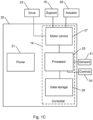
- Electrical unit 20 may include one or more components that enable operation of electrical or electronic components of wheeled mobility device 10. Components of electrical unit 20 may be located in a single housing (as shown in Figs. 1A and 1B , or may be located in two or more separate housings at various locations).
- Fig. 1C is a schematic block diagram of an electrical unit of the wheeled mobility device shown in Figs. 1A and 1B .
- Electrical unit 20 may include a controller 19 and a power source 21.
- power source 21 may include a storage battery, another type of battery, a solar panel, a generator, a connection to an external electrical power source (e.g., an electrical mains), or another source of electrical power.
- an external electrical power source e.g., an electrical mains
- Controller 19 may include a processor 25.
- Processor 25 may include one or more processing units or computers.
- Processor 25 may be configured to operate in accordance with programmed instructions.
- Processor 25 may communicate with data storage 29.
- data storage 29 may include one or more fixed or removable, volatile or non-volatile, remote or local, data storage units, memories, or computer-readable media.
- data storage 29 may be utilized to store one or more of programmed instructions for operation of processor 25, parameters or data that are utilized in executing programmed instructions, or results of execution of programmed instructions.
- Processor 25 may be configured to operate in accordance with one or more signals that are received from sensors 31.
- sensors 31 may include one or more sensors that are configured to detect a tilt of a component of tiltable leveling structure 12 or of user support 14.
- Sensors 31 may include one or more inertial measurement units, tilt sensors, accelerometers, gyroscopes, compasses, or other sensors that may be utilized to determine an orientation (e.g., yaw, pitch, roll) of tiltable leveling structure 12, of user support 14, or of chassis 11.
- Sensors 31 may include sensors for measuring the tilt or slope of a surface that supports wheeled mobility device 10.
- Sensors 31 may include a magnetometer or compass for measuring the orientation of mobility device 10 relative to the magnetic field of the Earth.
- Sensors 31 may include sensors for measuring a speed of rotation of one or more wheels (e.g., drive wheels 22 or support wheels 26). Sensors 31 may include one or more navigation sensors for determining a geographic position of wheeled mobility device 10. Sensors 31 may include force sensors for measuring a current load (e.g., weight) supported by wheeled mobility device 10, a charge level of a battery of power source 21, an impact, detecting an obstacle, or other types of sensors for detecting a potentially hazardous situation or other information.
- a current load e.g., weight
- Processor 25 may be configured to operate in accordance with control input that is received from one or more user controls 34.
- user controls 34 may be operated to indicate a desired orientation or direction of travel of wheeled mobility device 10, a desired speed of travel of wheeled mobility device 10, a desired configuration of user support 14 (e.g., seated or standing), or another indication of a command or preference by the user or another user or operator of wheeled mobility device 10.
- Controller 19 may include motor control 27.
- Processor 25 may be configured to communicate with motor control 27 to control one or more motors.
- Motor control 27 may include one or more controllers that are each configured to control operation of one or more motors.
- a motor that is controlled by motor control 27 may include a motor of a wheel drive 23, a motor of support conversion mechanism 18, or an actuator 60 of tiltable leveling structure 12.
- Processor 25 may be configured to apply one or more algorithms to calculate an operation of the motors on the basis of operation of user controls 34 and on the basis of one or more quantities sensed by sensors 31.
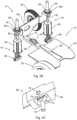
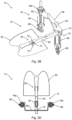
- Fig. 2A schematically illustrates a self-leveling mechanism of a wheeled mobility device, in accordance with an embodiment of the present invention.
- Fig. 2B is a schematic oblique view from below of the self-leveling mechanism shown in Fig. 2A.
- Fig. 2C is a schematic enlarged view of a swivel connection of a tiltable leveling structure of the self-leveling mechanism shown in Fig. 2B.
- Fig. 2D is a schematic top view of the self-leveling mechanism shown in Fig. 2A .
- Self-leveling mechanism 13 includes tiltable leveling structure 12 and linear actuator assemblies 61.
- Linear actuator assemblies 61 are operable by controller 19 to adjust a tilt of tiltable leveling structure 12 in accordance with a tilt measured by inertial measurement unit 40, or by another sensor of sensors 31.
- Shaft 75 of rod-end bearing 74 may be fixed to chassis floor 24 of chassis 11. Swivel bar 72 is located near a distal end of arm 64 of tiltable leveling structure 12. Swivel bar 72 may connect to (e.g., pass through a swivel opening 73 of) rod end bearing 74. Shaft 75 holds the opening of rod-end bearing 74, and thus swivel bar 72, at a fixed nonzero distance (e.g., with value H 0 ) above chassis floor 24. The connection to rod-end bearing 74 forms swivel connection 28. Swivel connection 28 may thus enable at least limited rotation of arm 64 and tiltable leveling structure 12 relative to shaft 75 and chassis 11.
- the fixed distance H 0 may be sufficient such that neither chassis floor 24 nor another structure of chassis 11 interferes with tilting of tiltable leveling structure 12 (within a predetermined range of tilt angles, e.g., selected to be sufficient to enable self-leveling of user support 14 when wheeled mobility device 10 travels over a surface whose maximum slope is within a predetermined range of slope angles).
- User support 14, including foot panel 32, is fixed to tiltable leveling structure 12.
- swivel connection 28 may enable sufficient tilting of user support 14 so as to maintain user support 14 in an approximately constant orientation with respect to the horizontal (typically constant roll and pitch angles with respect to the horizontal).
- Linear actuator assemblies 61 are each configured to linearly displace one of displaceable connections 16a and 16b.
- Actuator base 66 of each linear actuator assembly 61 may be fixed to chassis floor 24.
- each actuator 60 may be configured to rotate an actuator shaft 62 with exterior threading.
- Each of displaceable connections 16a and 16b may include connection structure 63 that includes an opening, sleeve, or ring with corresponding interior threading.
- the internal threading may be located in bore of ball swivel 65 of connection structure 63.
- Ball swivel 65 may enable at least a limited change in orientation of actuator shaft 62 relative to tilt plate 68 or other structure of tiltable leveling structure 12.
- actuator shaft 62 may displace displaceable connection 16a or 16b along actuator shaft 62 to increase or decrease a distance between the displaceable connection 16a or 16b and chassis floor 24.
- actuator base 66 may be configured to enable actuator shaft 62 and actuator 60 rotate or tilt relative to chassis floor 24, to enable tiltable leveling structure 12 to tilt relative to chassis floor 24.
- displaceable connection 16a or 16b may be fixed to actuator shaft 62.
- actuator shaft 62 may be extendible to increase a distance between the corresponding displaceable connection 16a or 16b and chassis floor 24.
- Actuator shaft 62 may be retractable to decrease the distance between the corresponding displaceable connection 16a or 16b and chassis floor 24.
- Each displaceable connection 16a or 16b is connected to an end of tilt plate 68.
- Tilt plate 68 is fixed to arm 64 at junction 70.
- raising or lowering displaceable connections 16a and 16b in tandem may raise or lower tilt plate 68 relative to swivel connection 28.
- the raising or lowering may change a pitch angle of arm 64, and thus of user support 14. Raising or lowering one of displaceable connections 16a and 16b relative to the other may change a lateral tilt of tilt plate 68.
- the raising or lowering of one of displaceable connections 16a and 16b relative to the other may change a roll angle of arm 64, and thus of user support 14.
- Alternative orientations of arm 64 and of displaceable connections 16a and 16b relative to a direction of forward motion of wheeled mobility device 10 e.g., arm 64 extending backward or to one side, with moveable points 16a and 16b being correspondingly located
- arm 64 extending backward or to one side, with moveable points 16a and 16b being correspondingly located
- Tiltable leveling structure 12 is provided with inertial measurement unit 40, or another sensor of sensors 31, for measuring a tilt of tiltable leveling structure 12.
- inertial measurement unit 40 may be mounted on arm 64 (as shown), on tilt plate 68, on foot panel 32, or elsewhere on tiltable leveling structure 12 or user support 14.
- Processor 25 may be configured to control operation of actuators 60 in accordance with tilt angles that are sensed by inertial measurement unit 40 or by another type of sensor 31, or that are calculated from quantities that are measured by inertial measurement unit 40 or another sensor 31.
- Fig. 3A schematically illustrates operation of a tiltable leveling structure of a wheeled mobility device, in accordance with an embodiment of the present invention.
- Fig. 3B schematically illustrates a cross sectional view along a lateral axis of the tiltable leveling structure shown in Fig. 3A , illustrating roll angle control.
- Fig. 3C schematically illustrates a cross sectional view along a longitudinal axis of the tiltable stabilizing structure shown in Fig. 3A , illustrating pitch angle control.
- tiltable stabilizing structure 12 is represented in Figs. 3A-3C by a representative plane 57.
- the representative plane 57 is parallel to a target plane 52.
- target plane 52 may be horizontal, or have another orientation that is preferred by a user of wheeled mobility device 10. (For example, a particular user may feel comfortable leaning slightly backward or forward, to the right or left, or at another target orientation.)
- Representative plane 57 may be understood to represent a plane that is defined by swivel connection 28 and by displaceable connections 16a and 16b.
- projected displaceable connections 58a and 58b are identical with displaceable connections 16a and 16b, respectively, with the tilt of target plane 52 adjusted accordingly (e.g., target plane 52 may not be horizontal when a component of wheeled mobility device 10, such as seat 36, is to be maintained horizontal).
- representative plane 57 may be defined such that the tilt of target plane 52 is identical to the tilt at which a component of wheeled mobility device 10, such as seat 36) is to be maintained (e.g., as defined with respect to the local horizontal and vertical).
- representative plane 57 of tiltable leveling structure 12 may be determined by initially defining a plane that is parallel to particular longitudinal axis 48 (e.g., an axis that is parallel to a projection of direction of forward motion 42 into target plane 52) and that includes displaceable connections 16a and 16b.
- Representative plane 57 then is a plane parallel to this defined plane that includes swivel connection 28.
- Projected displaceable connections 58a and 58b represent projections of displaceable connections 16a and 16b, respectively, into representative plane 57 along a line of translation of each displaceable connection 16a or 16b.
- the line of translation of displaceable connection 16a or 16b may be the axis of its corresponding actuator shaft 62.
- a displacement of projected displaceable connection 58a or 58b is equal to a displacement of the corresponding displaceable connection 16a or 16b.
- swivel connection 28 is located at or near a lateral midpoint of a front end of representative plane 57, the front end being determined by direction of forward motion 42.
- Projected displaceable connections 58a and 58b are located near left and right corners, respectively, of a rear end of representative plane 57.
- Other placements of swivel connection 28 and of projected displaceable connections 58a and 58b may be provided.
- a tilt of tiltable stabilizing structure 12 may be characterized with reference to a target plane 52.
- Representative plane 57 is characterized by longitudinal axis 48 (substantially parallel to direction of forward motion 42), and by lateral axis 44 (substantially perpendicular to longitudinal axis 48).
- a tilt resulting from a rotation of tiltable stabilizing structure 12 about lateral axis 44 with respect to target plane 52 may be quantified as pitch angle 46 (with value ⁇ P ).
- a tilt resulting from a rotation of tiltable stabilizing structure 12 about longitudinal axis 48 with respect to target plane 52 may be quantified as roll angle 50 (with value ⁇ R ).
- Values ⁇ P of pitch angle 46 and ⁇ R of roll angle 50 may be measured by inertial measurement unit 40, or by a similar sensor.
- Swivel connection 28 is located a constant distance 54 (with constant value H 0 ) from chassis floor 24.
- Distance 54 is sufficient such that when chassis 11 or wheeled mobility device 10 standing or travelling over a surface that is sloped within a predetermined range of slopes, projected displaceable connections 58a and 58b (and displaceable connections 16a and 16b) may be moved toward chassis floor 24 so as to maintain representative plane 57 in an orientation that is parallel to target plane 52.
- a maximum slope that is to be accommodated by motion of displaceable connections 16a and 16b may be a maximum slope upon which wheeled mobility device 10 may safely travel.
- Each of projected displaceable connections 58a and 58b is at a variable distance 56a or 56b, respectively (with changeable values H 1 and H 2 , respectively, e.g., within the range zero to 2H 0 ), from chassis floor 24.
- Variable distance 56a, 56b, or both may be changed by operating one or more actuators 60.
- projected displaceable connection 58 represents a point where a line through projected displaceable connections 58a and 58b intersects the plane of the section shown in Fig. 3C .
- Projected displaceable connection 58 is at a distance 56 from chassis floor 24.
- An iterative control algorithm may be applied by processor 25 to control operation of actuators 60 via motor control 27.
- Fig. 4 is a flowchart depicting a method for controlling a tiltable leveling structure of a wheeled mobility device, in accordance with an embodiment of the present invention.
- Fig. 5 is a block diagram of a control algorithm of the method depicted in Fig. 4 .
- Tilt control method 100 may be executed by processor 25 of wheeled mobility device 10.
- tilt control method 100 may be executed continually while power source 21 is switched on, while wheel drive 23 is operating, upon operation of a user control 34 to move or change a configuration of wheeled mobility device 10, or in response to another predetermined event or condition.
- One or more algorithm parameters 210 used in application of a control algorithm 200 may be predetermined or predefined (block 110). Such algorithm parameters 210 may include one or more gain factors, one or more factors related to operation of actuators 60, or other parameters used in application of control algorithm 200. For example, the parameters may include gain adjustment factors K P and K R , exponents p and r, length conversion factor ⁇ , or other parameters that are utilized during application of control algorithm 200 as described below.
- Algorithm parameters 210 may be defined, for example, during development of a model of a wheeled mobility device 10, during production, adjustment, maintenance or calibration of a particular wheeled mobility device 10, or otherwise. Algorithm parameters 210 may be adjusted in accordance with preferences of a user of a particular wheeled mobility device 10. For example, algorithm parameters 210 may affect smoothness or jerkiness of motions, preferred speed of motion, another user preference, or another characteristic of operation of wheeled mobility device 10.
- Target plane parameters 215 may be predetermined or predefined for characterizing target plane 52 (block 115).
- Target plane parameters 215 may include roll and pitch angles, or other parameters that define target plane 52.
- target plane parameters 215 may be defined during calibration, adjustment, or maintenance of a particular wheeled mobility device 10, during adaption of a particular wheeled mobility device 10 to a particular user, or at another time.
- Target plane parameters 215 may include, for example, a target pitch angle ⁇ P and a target roll angle ⁇ R .
- Values of ⁇ P > 0 may indicate a preference for a backward tilt, while ⁇ P ⁇ 0 may indicate a preference for a forward tilt.
- Tilt control method 100 is configured to adjust a tilt of tiltable stabilizing structure 12 with the goal of maintaining representative plane 57 parallel to target plane 52.
- Execution of tilt control method 100 includes a series of iterations. During each iteration, operation of actuators 60 is controlled in accordance with measurements and calculations that are made during that iteration. In the following, each iteration is numbered with an index i.
- Measured values of tilt angles of tiltable leveling structure 12 at the current iteration i may be obtained (blocks 120 and 220).
- the measured tilt angles may include pitch angle ⁇ P (i) and roll angle ⁇ R (i), or another set of angles that defines a tilt of tiltable stabilizing structure 12.
- the tilt angle measurements may be received from inertial measurement unit 40, or from another sensor. Alternatively or in addition, the tilt angle measurements may be obtained by analysis of received signals that indicate one or more measured quantities that are related to the tilt angles.
- a displacement of each of displaceable connections 16a and 16b to be applied during the current iteration may be calculated based on a deviation of the measured (block 130).
- the calculation may be considered to include the following steps:
- a displacement of each of displaceable connections 16a and 16b in order to correct the deviations ⁇ P (i) and ⁇ R (i) may be calculated on the basis of the deviation distances D P (i) and D R (i) (block 250).
- the calculated displacements are configured to reduce the values of ⁇ P (i) and ⁇ R (i) at the start of the next iteration (e.g., in the absence of any further change in the tilt of chassis 11 such as would be caused, e.g., by a change in slope of terrain or another surface that supports wheeled mobility device 10) to a value that is close to zero.
- the displacements may be calculated as linear combinations of the deviation distances D P (i) and D R (i).
- displaceable connection 16a and, equivalently, projected displaceable connection 58a
- H 1 i + 1 H 1 i ⁇ D P i + D R i .
- the displacements of H 1 and H 2 may be expressed in units of length (e.g., millimeters or centimeters), a rotation angle or number of rotations of actuator 60 (e.g., turning a screw of a screw mechanism, as shown, a screw of a scissor jack mechanism, an eccentric disk, or another mechanism for converting rotation of a motor to linear motion), or otherwise.
- actuator 60 e.g., turning a screw of a screw mechanism, as shown, a screw of a scissor jack mechanism, an eccentric disk, or another mechanism for converting rotation of a motor to linear motion
- the actuator 60 associated with each of displaceable connections 16a and 16b be operated to achieve the calculated displaced distances from chassis floor 24, H 1 (i + 1) and H 2 (i + 1), respectively, during the current iteration (block 140).
- a speed and direction of operation of each actuator 60 may be controlled (e.g., via operation of motor control 27) to achieve the calculated displaced distance by the start of the following iteration (returning to blocks 120 and 220).
- the speed of operation of each actuator 60 may be limited such that a rate of tilting of tiltable leveling structure 12 is in the range 1 degree per second to 10 degrees per second, e.g., about 4 degrees per second.
- the control loop may be described as having an adaptive bandwidth: wider for larger errors and narrower for smaller errors.
- Values of exponents p and r, as well as those of factors K P , K R , and ⁇ , may be selected in accordance with one or more of properties or characteristics of a particular or representative wheeled mobility device 10, of a preference of a particular or representative user of wheeled mobility device 10, or otherwise.
- a user self-leveling apparatus for wheeled mobility device 10 and a tilt control method 100 may be advantageous over other types of self-leveling systems.
- the mechanism for tilting tiltable stabilizing structure 12, using linear actuators and a fixed swivel connection 28, may be advantageous over double-gimbal mechanism with angular actuators for producing two mutually orthogonal rotations.
- the mechanism for tilting tiltable leveling structure 12 may occupy less space, require less maintenance, and may be less expensive than a typical double-gimbal mechanism.
- Actuators 60 produce linear translation only and are not orthogonal to each other (such that movement of each of displaceable connections 16a and 16b affects both roll and pitch),
- control algorithm 200 may be robust, simpler, and more easily configured than an algorithm for controlling a double-gimbal mechanism.
- the control algorithm 200 is configured to always converge to the orientation of representative plane 57 that of target plane 52, even in the presence of small mechanical inaccuracies such as backlash.
- Control algorithm 200 may be advantageous over other algorithms (such as PID) due to its simplicity, smooth operation, and robustness.
- Application of an adaptive control-loop, as in application of control algorithm 200, may prevent overshooting, undershooting, and limit-cycle phenomena.
Landscapes
- Health & Medical Sciences (AREA)
- Life Sciences & Earth Sciences (AREA)
- Animal Behavior & Ethology (AREA)
- General Health & Medical Sciences (AREA)
- Public Health (AREA)
- Veterinary Medicine (AREA)
- Engineering & Computer Science (AREA)
- Mechanical Engineering (AREA)
- Motorcycle And Bicycle Frame (AREA)
Claims (12)
- Mobilitätsvorrichtung (10) zum Stützen eines Benutzers in sitzender, stehender oder anderer Position, umfassend:ein Fahrgestell (11), das dazu konfiguriert ist, die Mobilitätsvorrichtung auf einer Oberfläche anzutreiben; undeinen Selbstnivellierungsmechanismus (13), umfassend:eine Nivellierstruktur (12), an der eine Benutzerstütze (14) zur Unterstützung eines Benutzers der Mobilitätsvorrichtung angebracht ist, wobei die Nivellierstruktur mit dem Fahrgestell (11) durch eine Schwenkverbindung (28), die eine Nick- und Rollbewegung der Nivellierstruktur ermöglicht, und durch zwei linear verschiebbare Verbindungen (16a, 16b), die seitlich zueinander versetzt sind, verbunden ist;zwei Linearaktuatoren (61), von denen jeder dazu konfiguriert ist, eine verschiebbare Verbindung der beiden verschiebbaren Verbindungen (16a, 16b) zu verschieben, um einen Abstand zwischen der Benutzerstütze und dem Fahrgestell (11) einzustellen;einen Sensor (31) zum Erfassen einer Neigung der Nivellierstruktur (12) in Bezug auf eine vorgegebene Ebene, der dazu konfiguriert ist, einen Nickwinkel und einen Rollwinkel der Benutzerstütze (14) zu messen; undeine Steuereinrichtung (19), die dazu konfiguriert ist, die Linearaktuatoren (61) in Übereinstimmung mit einer Neigung zu betätigen, die von dem Sensor (31) erfasst wird, um die Ausrichtung der Benutzerstütze (14) beizubehalten,dadurch gekennzeichnet, dassdie Steuereinrichtung (19) dazu konfiguriert ist, einen iterativen adaptiven Steueralgorithmus anzuwenden, um eine Verschiebung einer oder beider verschiebbarer Verbindungen in Übereinstimmung mit einer Abweichung des gemessenen Nickwinkels von einem Nickwinkel einer Zielebene oder einer Abweichung des gemessenen Rollwinkels von einem Rollwinkel der Zielebene zu berechnen, und wobei die Größe der berechneten Verschiebung während einer einzelnen Iteration des Steueralgorithmus zunimmt, wenn die Abweichung zunimmt, und abnimmt, wenn die Abweichung abnimmt,einen Stützenumwandlungsmechanismus (18), um die Benutzerstütze (14) von einer sitzenden Konfiguration in eine stehende Konfiguration umzuwandeln und umgekehrt,wobei die Benutzerstütze (14) der Nivellierstruktur (12) dazu konfiguriert ist, den Benutzer in sitzender, stehender oder anderer Position zu unterstützen.
- Vorrichtung nach Anspruch 1, wobei die Schwenkverbindung (28) ein Gelenkkopflager umfasst.
- Vorrichtung nach Anspruch 1 oder 2, wobei sich die Schwenkverbindung (28) in einem festen Abstand ungleich null von einem Boden des Fahrgestells befindet.
- Vorrichtung nach einem der Ansprüche 1 bis 3, wobei die Schwenkverbindung entlang eines Arms der Nivellierstruktur (12) angeordnet ist.
- Vorrichtung nach Anspruch 4, wobei sich die Schwenkverbindung an einem Ende der Nivellierstruktur (12) befindet und die beiden verschiebbaren Verbindungen (16a, 16b) an einem gegenüberliegenden Ende der Nivellierstruktur (12) angeordnet sind.
- Vorrichtung nach einem der Ansprüche 1 bis 5, wobei der Linearaktuator (61) einen Gewindemechanismus umfasst.
- Vorrichtung nach Anspruch 6, wobei die Schwenkverbindung ein Kugelgelenk (65) umfasst.
- Vorrichtung nach einem der Ansprüche 1 bis 7, wobei jede der verschiebbaren Verbindungen dazu konfiguriert ist, von ihrem Linearaktuator im Wesentlichen vertikal verschoben zu werden.
- Vorrichtung nach Anspruch 1, wobei der Sensor (31) eine Trägheitsmesseinheit umfasst, die aus einer Gruppe ausgewählt ist, die aus einem oder mehreren Gyroskopen, Beschleunigungsmessern, fusionierten Gyroskop-Beschleunigungsmessern, Neigungsmessern oder Neigungssensoren besteht.
- Vorrichtung nach einem der Ansprüche 1 bis 9, wobei der Umwandlungsmechanismus (18) dazu konfiguriert ist, eine Konfiguration der Benutzerstütze (14) zwischen einer Konfiguration zum Stützen des Benutzers in stehender Position und einer Konfiguration zum Stützen des Benutzers in sitzender Position zu ändern, während der Schwerpunkt der Mobilitätsvorrichtung (10) mit Rädern in einer im Wesentlichen konstanten Quer- und Längsposition relativ zum Fahrgestell (11) gehalten wird.
- Verfahren zum Steuern einer Neigung einer Benutzerstütze (14) einer Mobilitätsvorrichtung (10) nach einem der Ansprüche 1 bis 10, wobei das Verfahren umfasst:Empfangen des Ergebnisses des Sensors (31);Berechnen einer Verschiebung, die für jede verschiebbare Verbindung erforderlich ist, um die Benutzerstütze (14) in eine definierte Ausrichtung zu kippen; undBetätigen des Linearaktuators jeder der verschiebbaren Verbindungen, um jede der verschiebbaren Verbindungen um die berechnete Verschiebung zu verschieben.
- Verfahren nach Anspruch 11, wobei das Empfangen des Sensorergebnisses einen Nickwinkel und einen Rollwinkel umfasst, wobei die Abweichung der erfassten Neigung der selbstnivellierenden Struktur von der Ausrichtung der Zielebene Folgendes umfasst:eine Nickwinkelabweichung des erfassten Nickwinkels von einem Nickwinkel einer Zielebene und eine Rollwinkelabweichung des erfassten Rollwinkels von einem Rollwinkel der Zielebene;wobei das Berechnen der linearen Verschiebung das Berechnen einer linearen Kombination aus einem Nickabweichungsabstand umfasst, der unter Verwendung der Nickwinkelabweichung berechnet wird, und einem Rollabweichungsabstand, der unter Verwendung der Rollwinkelabweichung berechnet wird; undwobei die Berechnung des Nickabweichungsabstands das Erhöhen eines Absolutwerts der Nickwinkelabweichung auf eine positive Potenz umfasst oder die Berechnung des Rollabweichungsabstands das Erhöhen eines Absolutwerts der Rollwinkelabweichung auf eine positive Potenz umfasst; und/oder das Betreiben eines Aktuators der beiden Linearaktuatoren das Steuern einer Drehgeschwindigkeit eines Motors des Aktuators umfasst.
Applications Claiming Priority (2)
| Application Number | Priority Date | Filing Date | Title |
|---|---|---|---|
| US15/196,109 US10525784B2 (en) | 2016-06-29 | 2016-06-29 | Self-leveling mechanism and method for wheeled mobility device |
| PCT/IL2017/050405 WO2018002909A1 (en) | 2016-06-29 | 2017-04-04 | Self-leveling mechanism and method for a standing wheeled mobility device |
Publications (3)
| Publication Number | Publication Date |
|---|---|
| EP3478239A1 EP3478239A1 (de) | 2019-05-08 |
| EP3478239A4 EP3478239A4 (de) | 2020-02-19 |
| EP3478239B1 true EP3478239B1 (de) | 2025-01-15 |
Family
ID=60786955
Family Applications (1)
| Application Number | Title | Priority Date | Filing Date |
|---|---|---|---|
| EP17819481.7A Active EP3478239B1 (de) | 2016-06-29 | 2017-04-04 | Selbstnivellierungsmechanismus und verfahren für eine mobilitätsvorrichtung mit rädernfür einen benutzer in sitzender, stehender oder anderer position |
Country Status (3)
| Country | Link |
|---|---|
| US (1) | US10525784B2 (de) |
| EP (1) | EP3478239B1 (de) |
| WO (1) | WO2018002909A1 (de) |
Families Citing this family (24)
| Publication number | Priority date | Publication date | Assignee | Title |
|---|---|---|---|---|
| CA2801334C (en) | 2010-06-03 | 2020-03-10 | Polaris Industries Inc. | Electronic throttle control |
| US9205717B2 (en) | 2012-11-07 | 2015-12-08 | Polaris Industries Inc. | Vehicle having suspension with continuous damping control |
| CN107406094B (zh) | 2014-10-31 | 2020-04-14 | 北极星工业有限公司 | 用于控制车辆的系统和方法 |
| CN110121438B (zh) | 2016-11-18 | 2023-01-31 | 北极星工业有限公司 | 具有可调节悬架的车辆 |
| US10101152B1 (en) * | 2017-03-30 | 2018-10-16 | Caterpillar Inc. | Object detection sensor alignment monitoring system |
| US10973715B2 (en) * | 2017-05-23 | 2021-04-13 | William Baer | Powered pedestrian apparatus |
| US10406884B2 (en) | 2017-06-09 | 2019-09-10 | Polaris Industries Inc. | Adjustable vehicle suspension system |
| EP3578154B1 (de) * | 2018-06-05 | 2021-08-04 | Matia Robotics Mekatronik Sistemler AR-GE Mühendislik Yazilim Sanayi ve Ticaret Anonim Sirketi | Innen- und aussenmobilitätsvorrichtungssystem |
| US12167793B2 (en) * | 2018-11-14 | 2024-12-17 | Ohad Paz | Tilting/lifting chair |
| US20200229998A1 (en) | 2018-11-14 | 2020-07-23 | Ohad Paz | Smart tilting/lifting chair with the ability to tilt user to vertical position |
| US10987987B2 (en) * | 2018-11-21 | 2021-04-27 | Polaris Industries Inc. | Vehicle having adjustable compression and rebound damping |
| EP4003764B1 (de) * | 2019-07-31 | 2024-05-01 | Vibracoustic SE | Vorrichtung und verfahren zum verstellen eines fusspunktes eines federelements fuer ein fahrzeug |
| CN110764522A (zh) * | 2019-10-30 | 2020-02-07 | 贵州航天特种车有限责任公司 | 一种基于倾角补偿的调平控制系统及其方法 |
| CN120735865A (zh) | 2020-05-20 | 2025-10-03 | 北极星工业有限公司 | 用于非道路休闲车辆的可调悬架的系统和方法 |
| US11904648B2 (en) | 2020-07-17 | 2024-02-20 | Polaris Industries Inc. | Adjustable suspensions and vehicle operation for off-road recreational vehicles |
| US11478082B2 (en) * | 2020-12-22 | 2022-10-25 | Barbara Gervais | Care chair |
| CN114035617B (zh) * | 2021-11-08 | 2024-04-19 | 南京晨光集团有限责任公司 | 一种车载调平系统及其高精度控制方法 |
| JP7805191B2 (ja) * | 2022-02-08 | 2026-01-23 | 本田技研工業株式会社 | 乗り物 |
| JP7742783B2 (ja) * | 2022-02-08 | 2025-09-22 | 本田技研工業株式会社 | 乗り物 |
| JP7753127B2 (ja) * | 2022-02-08 | 2025-10-14 | 本田技研工業株式会社 | 乗り物 |
| JP7795946B2 (ja) * | 2022-03-17 | 2026-01-08 | 本田技研工業株式会社 | 乗り物 |
| JP7788900B2 (ja) * | 2022-03-18 | 2025-12-19 | 本田技研工業株式会社 | 乗り物 |
| WO2024044543A2 (en) * | 2022-08-22 | 2024-02-29 | Jay Johnson | Mobile standing frame |
| US12022949B2 (en) * | 2022-10-13 | 2024-07-02 | Hidden Lake 822, Llc | Drive motor-linear actuator system for powered lift or powered reclining chairs |
Family Cites Families (37)
| Publication number | Priority date | Publication date | Assignee | Title |
|---|---|---|---|---|
| US2707986A (en) * | 1953-03-19 | 1955-05-10 | Leslie W Johnson | Resilient support for tractor seat |
| US3869011A (en) * | 1973-01-02 | 1975-03-04 | Ramby Inc | Stair climbing tracked vehicle |
| US4054319A (en) * | 1975-10-23 | 1977-10-18 | The United States Of America As Represented By The Secretary Of The Navy | Stand-aid invalid wheelchair |
| US4194584A (en) * | 1978-07-17 | 1980-03-25 | Delany James F | Variable terrain vehicle |
| US4566707A (en) * | 1981-11-05 | 1986-01-28 | Nitzberg Leonard R | Wheel chair |
| US4437537A (en) * | 1982-01-25 | 1984-03-20 | Ausmus Donald L | Vehicle for supporting handicapped occupants |
| JPS59211451A (ja) * | 1983-05-10 | 1984-11-30 | ソシエテ・ア・レスポンサビリテ・リミテ・アンテルナショナル・ディフュ−ジョン・コンソマトゥ−ル | 身体障害者用車椅子のための身体保持装置 |
| FR2553650B1 (fr) | 1983-10-20 | 1986-02-21 | Int Diffusion Consomma | Repose-pieds amovible pour fauteuil roulant comportant une structure de verticalisation |
| US5346280A (en) * | 1992-03-31 | 1994-09-13 | Deumite Norman A | Chair with automatic standing aid |
| US5701965A (en) * | 1993-02-24 | 1997-12-30 | Deka Products Limited Partnership | Human transporter |
| US6543564B1 (en) * | 1994-05-27 | 2003-04-08 | Deka Products Limited Partnership | Balancing personal vehicle |
| US5577567A (en) * | 1994-12-20 | 1996-11-26 | Johnson; Robert E. | Stair climbing wheelchair |
| US6068280A (en) * | 1996-09-13 | 2000-05-30 | Torres; Hank G. | Self-leveling seat for a wheelchair |
| US6231067B1 (en) * | 1998-01-12 | 2001-05-15 | Fena Design, Inc. | Motorized standing wheelchair |
| US6125957A (en) * | 1998-02-10 | 2000-10-03 | Kauffmann; Ricardo M. | Prosthetic apparatus for supporting a user in sitting or standing positions |
| EP0994009B1 (de) * | 1998-10-16 | 2004-12-01 | Same Deutz-Fahr Group Spa | Landwirtschaftliche Maschine mit selbstausrichtendem Führerhaus |
| DE60021709T2 (de) * | 1999-03-15 | 2006-06-01 | Deka Products Ltd. Partnership | Steuerungssystem und -verfahren für rollstühle |
| FR2813524B1 (fr) * | 2000-09-07 | 2002-12-06 | Idc Medical | Systeme de verrouillage pour dispositif de maintien corporel pour fauteuil verticalisateur |
| NZ539543A (en) * | 2005-04-20 | 2008-02-29 | Graham John Mahy | Vehicle with adjustable track width and wheelbase |
| FR2890855B1 (fr) | 2005-09-20 | 2007-12-14 | Lifestand Vivre Debout Soc Res | Siege verticalisateur a moyens de reglage de l'inclinaison du repose-pieds en position verticalisee. |
| JP4923605B2 (ja) | 2006-02-13 | 2012-04-25 | スズキ株式会社 | 電動車椅子 |
| US7635164B2 (en) * | 2006-10-23 | 2009-12-22 | Hank Torres | Therapeutic automated automatically controlled shifting wheelchair seat |
| CA2676724C (en) * | 2007-02-14 | 2013-12-17 | Invacare Corporation | Stability control system |
| JP2009035218A (ja) * | 2007-08-03 | 2009-02-19 | Nissan Motor Co Ltd | 能動型サスペンション、および車両の姿勢変化抑制方法 |
| US8170780B2 (en) * | 2008-11-06 | 2012-05-01 | Segway, Inc. | Apparatus and method for control of a vehicle |
| WO2010140560A1 (ja) | 2009-06-01 | 2010-12-09 | 株式会社テムザック | 移乗・移動装置 |
| US8702108B2 (en) * | 2010-02-23 | 2014-04-22 | Zoomability Ab | Vehicle having a level compensation system |
| WO2011123726A2 (en) * | 2010-03-31 | 2011-10-06 | Linear Signal, Inc. | Apparatus and system for a double gimbal stabilization platform |
| JP2012051385A (ja) * | 2010-08-31 | 2012-03-15 | Hitachi Ltd | 移動機構 |
| US8567804B1 (en) * | 2011-05-25 | 2013-10-29 | Jody M. Hoenhause | Mobile device for supporting a user in a standing, sitting, or kneeling position |
| US8973997B2 (en) * | 2011-07-19 | 2015-03-10 | Skip's Patents, Llc | Seat structure with sit-to-stand feature |
| US10045895B2 (en) * | 2011-08-24 | 2018-08-14 | Liko Research & Development Ab | Patient stand assist and therapy devices and methods |
| US9044369B2 (en) * | 2011-11-04 | 2015-06-02 | The United States Of America, As Represented By The Department Of Veterans Affairs | Mobile manual standing wheelchair |
| US9173792B2 (en) * | 2013-08-28 | 2015-11-03 | Upnride Robotics Ltd | Standing wheelchair |
| KR101545692B1 (ko) | 2014-05-30 | 2015-08-19 | 주식회사 퓨트로닉 | 구동 제어 및 모니터링 시스템을 구비한 기립형 전동의자 |
| US9073399B1 (en) * | 2014-10-10 | 2015-07-07 | Max Mobility, Llc | System and method for adjusting a wheelchair seat |
| US9682603B2 (en) * | 2014-10-10 | 2017-06-20 | Max Mobility, Llc | System and method for adjusting a wheelchair seat |
-
2016
- 2016-06-29 US US15/196,109 patent/US10525784B2/en active Active
-
2017
- 2017-04-04 WO PCT/IL2017/050405 patent/WO2018002909A1/en not_active Ceased
- 2017-04-04 EP EP17819481.7A patent/EP3478239B1/de active Active
Also Published As
| Publication number | Publication date |
|---|---|
| EP3478239A1 (de) | 2019-05-08 |
| US10525784B2 (en) | 2020-01-07 |
| EP3478239A4 (de) | 2020-02-19 |
| US20180001729A1 (en) | 2018-01-04 |
| WO2018002909A1 (en) | 2018-01-04 |
Similar Documents
| Publication | Publication Date | Title |
|---|---|---|
| EP3478239B1 (de) | Selbstnivellierungsmechanismus und verfahren für eine mobilitätsvorrichtung mit rädernfür einen benutzer in sitzender, stehender oder anderer position | |
| US6571892B2 (en) | Control system and method | |
| EP1161214B1 (de) | Schwerpunktausgleichvorrichtung für fahrzeuge | |
| US9682603B2 (en) | System and method for adjusting a wheelchair seat | |
| AU774856B2 (en) | System and method for control scheduling | |
| JP6317447B2 (ja) | 起立式車椅子 | |
| US9073399B1 (en) | System and method for adjusting a wheelchair seat | |
| US9149399B2 (en) | Stair climbing vehicle | |
| CN100539979C (zh) | 电动车 | |
| US12048655B2 (en) | Low-profile and high-load ball-balancing rolling system | |
| US20190231617A1 (en) | Mobility assistance vehicle designed to negotiate obstacles | |
| JP2004001699A (ja) | 段差昇降方法、台車及び車椅子 | |
| EP3812256A1 (de) | Mobiler körper | |
| JP5943154B2 (ja) | 手押し車 | |
| JP7307706B2 (ja) | 移動体 | |
| KR20150138748A (ko) | 계단 승강 로봇 및 그 제어방법 | |
| Chocoteco et al. | Improving the climbing/descent performance of stair-climbing mobility systems confronting architectural barriers with geometric disturbances | |
| KR20120004591A (ko) | 자동 자세보정형 휠체어 | |
| KR20160055731A (ko) | 계단 승강 로봇 및 그 제어방법 | |
| JP2015047985A (ja) | 階段昇降機 | |
| JP2015047987A (ja) | 階段昇降機 | |
| JP6253079B2 (ja) | 手動車両の電動化ユニット及び手動車両の電動化ユニットの制御方法並びに電動車いす及び電動車いすの制御方法 | |
| JP2020031763A (ja) | 歩行補助装置および歩行補助装置の制御プログラム | |
| JP2016132445A (ja) | バランス訓練システム |
Legal Events
| Date | Code | Title | Description |
|---|---|---|---|
| STAA | Information on the status of an ep patent application or granted ep patent |
Free format text: STATUS: THE INTERNATIONAL PUBLICATION HAS BEEN MADE |
|
| PUAI | Public reference made under article 153(3) epc to a published international application that has entered the european phase |
Free format text: ORIGINAL CODE: 0009012 |
|
| STAA | Information on the status of an ep patent application or granted ep patent |
Free format text: STATUS: REQUEST FOR EXAMINATION WAS MADE |
|
| 17P | Request for examination filed |
Effective date: 20190128 |
|
| AK | Designated contracting states |
Kind code of ref document: A1 Designated state(s): AL AT BE BG CH CY CZ DE DK EE ES FI FR GB GR HR HU IE IS IT LI LT LU LV MC MK MT NL NO PL PT RO RS SE SI SK SM TR |
|
| AX | Request for extension of the european patent |
Extension state: BA ME |
|
| DAV | Request for validation of the european patent (deleted) | ||
| DAX | Request for extension of the european patent (deleted) | ||
| A4 | Supplementary search report drawn up and despatched |
Effective date: 20200122 |
|
| RIC1 | Information provided on ipc code assigned before grant |
Ipc: A61G 5/04 20130101ALI20200116BHEP Ipc: B60G 17/019 20060101ALI20200116BHEP Ipc: A61G 5/10 20060101ALI20200116BHEP Ipc: A61G 5/12 20060101ALI20200116BHEP Ipc: A61G 5/14 20060101AFI20200116BHEP |
|
| STAA | Information on the status of an ep patent application or granted ep patent |
Free format text: STATUS: EXAMINATION IS IN PROGRESS |
|
| 17Q | First examination report despatched |
Effective date: 20220203 |
|
| GRAP | Despatch of communication of intention to grant a patent |
Free format text: ORIGINAL CODE: EPIDOSNIGR1 |
|
| STAA | Information on the status of an ep patent application or granted ep patent |
Free format text: STATUS: GRANT OF PATENT IS INTENDED |
|
| INTG | Intention to grant announced |
Effective date: 20240909 |
|
| GRAS | Grant fee paid |
Free format text: ORIGINAL CODE: EPIDOSNIGR3 |
|
| GRAA | (expected) grant |
Free format text: ORIGINAL CODE: 0009210 |
|
| STAA | Information on the status of an ep patent application or granted ep patent |
Free format text: STATUS: THE PATENT HAS BEEN GRANTED |
|
| AK | Designated contracting states |
Kind code of ref document: B1 Designated state(s): AL AT BE BG CH CY CZ DE DK EE ES FI FR GB GR HR HU IE IS IT LI LT LU LV MC MK MT NL NO PL PT RO RS SE SI SK SM TR |
|
| REG | Reference to a national code |
Ref country code: CH Ref legal event code: EP Ref country code: GB Ref legal event code: FG4D |
|
| REG | Reference to a national code |
Ref country code: DE Ref legal event code: R096 Ref document number: 602017087367 Country of ref document: DE |
|
| REG | Reference to a national code |
Ref country code: IE Ref legal event code: FG4D |
|
| REG | Reference to a national code |
Ref country code: NL Ref legal event code: MP Effective date: 20250115 |
|
| PG25 | Lapsed in a contracting state [announced via postgrant information from national office to epo] |
Ref country code: NL Free format text: LAPSE BECAUSE OF FAILURE TO SUBMIT A TRANSLATION OF THE DESCRIPTION OR TO PAY THE FEE WITHIN THE PRESCRIBED TIME-LIMIT Effective date: 20250115 |
|
| PG25 | Lapsed in a contracting state [announced via postgrant information from national office to epo] |
Ref country code: RS Free format text: LAPSE BECAUSE OF FAILURE TO SUBMIT A TRANSLATION OF THE DESCRIPTION OR TO PAY THE FEE WITHIN THE PRESCRIBED TIME-LIMIT Effective date: 20250415 |
|
| PG25 | Lapsed in a contracting state [announced via postgrant information from national office to epo] |
Ref country code: FI Free format text: LAPSE BECAUSE OF FAILURE TO SUBMIT A TRANSLATION OF THE DESCRIPTION OR TO PAY THE FEE WITHIN THE PRESCRIBED TIME-LIMIT Effective date: 20250115 |
|
| PG25 | Lapsed in a contracting state [announced via postgrant information from national office to epo] |
Ref country code: PL Free format text: LAPSE BECAUSE OF FAILURE TO SUBMIT A TRANSLATION OF THE DESCRIPTION OR TO PAY THE FEE WITHIN THE PRESCRIBED TIME-LIMIT Effective date: 20250115 |
|
| PGFP | Annual fee paid to national office [announced via postgrant information from national office to epo] |
Ref country code: DE Payment date: 20250319 Year of fee payment: 9 |
|
| PG25 | Lapsed in a contracting state [announced via postgrant information from national office to epo] |
Ref country code: ES Free format text: LAPSE BECAUSE OF FAILURE TO SUBMIT A TRANSLATION OF THE DESCRIPTION OR TO PAY THE FEE WITHIN THE PRESCRIBED TIME-LIMIT Effective date: 20250115 |
|
| REG | Reference to a national code |
Ref country code: LT Ref legal event code: MG9D |
|
| PG25 | Lapsed in a contracting state [announced via postgrant information from national office to epo] |
Ref country code: IS Free format text: LAPSE BECAUSE OF FAILURE TO SUBMIT A TRANSLATION OF THE DESCRIPTION OR TO PAY THE FEE WITHIN THE PRESCRIBED TIME-LIMIT Effective date: 20250515 Ref country code: NO Free format text: LAPSE BECAUSE OF FAILURE TO SUBMIT A TRANSLATION OF THE DESCRIPTION OR TO PAY THE FEE WITHIN THE PRESCRIBED TIME-LIMIT Effective date: 20250415 |
|
| REG | Reference to a national code |
Ref country code: AT Ref legal event code: MK05 Ref document number: 1759381 Country of ref document: AT Kind code of ref document: T Effective date: 20250115 |
|
| PG25 | Lapsed in a contracting state [announced via postgrant information from national office to epo] |
Ref country code: HR Free format text: LAPSE BECAUSE OF FAILURE TO SUBMIT A TRANSLATION OF THE DESCRIPTION OR TO PAY THE FEE WITHIN THE PRESCRIBED TIME-LIMIT Effective date: 20250115 |
|
| PG25 | Lapsed in a contracting state [announced via postgrant information from national office to epo] |
Ref country code: LV Free format text: LAPSE BECAUSE OF FAILURE TO SUBMIT A TRANSLATION OF THE DESCRIPTION OR TO PAY THE FEE WITHIN THE PRESCRIBED TIME-LIMIT Effective date: 20250115 Ref country code: PT Free format text: LAPSE BECAUSE OF FAILURE TO SUBMIT A TRANSLATION OF THE DESCRIPTION OR TO PAY THE FEE WITHIN THE PRESCRIBED TIME-LIMIT Effective date: 20250515 |
|
| PG25 | Lapsed in a contracting state [announced via postgrant information from national office to epo] |
Ref country code: GR Free format text: LAPSE BECAUSE OF FAILURE TO SUBMIT A TRANSLATION OF THE DESCRIPTION OR TO PAY THE FEE WITHIN THE PRESCRIBED TIME-LIMIT Effective date: 20250416 Ref country code: BG Free format text: LAPSE BECAUSE OF FAILURE TO SUBMIT A TRANSLATION OF THE DESCRIPTION OR TO PAY THE FEE WITHIN THE PRESCRIBED TIME-LIMIT Effective date: 20250115 |
|
| PG25 | Lapsed in a contracting state [announced via postgrant information from national office to epo] |
Ref country code: AT Free format text: LAPSE BECAUSE OF FAILURE TO SUBMIT A TRANSLATION OF THE DESCRIPTION OR TO PAY THE FEE WITHIN THE PRESCRIBED TIME-LIMIT Effective date: 20250115 |
|
| PG25 | Lapsed in a contracting state [announced via postgrant information from national office to epo] |
Ref country code: SE Free format text: LAPSE BECAUSE OF FAILURE TO SUBMIT A TRANSLATION OF THE DESCRIPTION OR TO PAY THE FEE WITHIN THE PRESCRIBED TIME-LIMIT Effective date: 20250115 |
|
| PG25 | Lapsed in a contracting state [announced via postgrant information from national office to epo] |
Ref country code: SM Free format text: LAPSE BECAUSE OF FAILURE TO SUBMIT A TRANSLATION OF THE DESCRIPTION OR TO PAY THE FEE WITHIN THE PRESCRIBED TIME-LIMIT Effective date: 20250115 |
|
| PG25 | Lapsed in a contracting state [announced via postgrant information from national office to epo] |
Ref country code: DK Free format text: LAPSE BECAUSE OF FAILURE TO SUBMIT A TRANSLATION OF THE DESCRIPTION OR TO PAY THE FEE WITHIN THE PRESCRIBED TIME-LIMIT Effective date: 20250115 |
|
| PG25 | Lapsed in a contracting state [announced via postgrant information from national office to epo] |
Ref country code: IT Free format text: LAPSE BECAUSE OF FAILURE TO SUBMIT A TRANSLATION OF THE DESCRIPTION OR TO PAY THE FEE WITHIN THE PRESCRIBED TIME-LIMIT Effective date: 20250115 |
|
| REG | Reference to a national code |
Ref country code: DE Ref legal event code: R097 Ref document number: 602017087367 Country of ref document: DE |
|
| PG25 | Lapsed in a contracting state [announced via postgrant information from national office to epo] |
Ref country code: CZ Free format text: LAPSE BECAUSE OF FAILURE TO SUBMIT A TRANSLATION OF THE DESCRIPTION OR TO PAY THE FEE WITHIN THE PRESCRIBED TIME-LIMIT Effective date: 20250115 Ref country code: EE Free format text: LAPSE BECAUSE OF FAILURE TO SUBMIT A TRANSLATION OF THE DESCRIPTION OR TO PAY THE FEE WITHIN THE PRESCRIBED TIME-LIMIT Effective date: 20250115 |
|
| PG25 | Lapsed in a contracting state [announced via postgrant information from national office to epo] |
Ref country code: RO Free format text: LAPSE BECAUSE OF FAILURE TO SUBMIT A TRANSLATION OF THE DESCRIPTION OR TO PAY THE FEE WITHIN THE PRESCRIBED TIME-LIMIT Effective date: 20250115 |
|
| PG25 | Lapsed in a contracting state [announced via postgrant information from national office to epo] |
Ref country code: SK Free format text: LAPSE BECAUSE OF FAILURE TO SUBMIT A TRANSLATION OF THE DESCRIPTION OR TO PAY THE FEE WITHIN THE PRESCRIBED TIME-LIMIT Effective date: 20250115 |
|
| PLBE | No opposition filed within time limit |
Free format text: ORIGINAL CODE: 0009261 |
|
| STAA | Information on the status of an ep patent application or granted ep patent |
Free format text: STATUS: NO OPPOSITION FILED WITHIN TIME LIMIT |
|
| REG | Reference to a national code |
Ref country code: CH Ref legal event code: H13 Free format text: ST27 STATUS EVENT CODE: U-0-0-H10-H13 (AS PROVIDED BY THE NATIONAL OFFICE) Effective date: 20251125 |
|
| REG | Reference to a national code |
Ref country code: CH Ref legal event code: L10 Free format text: ST27 STATUS EVENT CODE: U-0-0-L10-L00 (AS PROVIDED BY THE NATIONAL OFFICE) Effective date: 20251126 |
|
| PG25 | Lapsed in a contracting state [announced via postgrant information from national office to epo] |
Ref country code: LU Free format text: LAPSE BECAUSE OF NON-PAYMENT OF DUE FEES Effective date: 20250404 |
|
| PG25 | Lapsed in a contracting state [announced via postgrant information from national office to epo] |
Ref country code: MC Free format text: LAPSE BECAUSE OF FAILURE TO SUBMIT A TRANSLATION OF THE DESCRIPTION OR TO PAY THE FEE WITHIN THE PRESCRIBED TIME-LIMIT Effective date: 20250115 |
|
| 26N | No opposition filed |
Effective date: 20251016 |
|
| REG | Reference to a national code |
Ref country code: BE Ref legal event code: MM Effective date: 20250430 |
|
| PG25 | Lapsed in a contracting state [announced via postgrant information from national office to epo] |
Ref country code: BE Free format text: LAPSE BECAUSE OF NON-PAYMENT OF DUE FEES Effective date: 20250430 |
|
| PG25 | Lapsed in a contracting state [announced via postgrant information from national office to epo] |
Ref country code: CH Free format text: LAPSE BECAUSE OF NON-PAYMENT OF DUE FEES Effective date: 20250430 |
|
| PGFP | Annual fee paid to national office [announced via postgrant information from national office to epo] |
Ref country code: GB Payment date: 20260319 Year of fee payment: 10 |
|
| PG25 | Lapsed in a contracting state [announced via postgrant information from national office to epo] |
Ref country code: IE Free format text: LAPSE BECAUSE OF NON-PAYMENT OF DUE FEES Effective date: 20250404 |
|
| PGFP | Annual fee paid to national office [announced via postgrant information from national office to epo] |
Ref country code: FR Payment date: 20260319 Year of fee payment: 10 |