EP3477802A1 - Stabilisierungsanordnung für den transport eines schaltschranks - Google Patents
Stabilisierungsanordnung für den transport eines schaltschranks Download PDFInfo
- Publication number
- EP3477802A1 EP3477802A1 EP17198430.5A EP17198430A EP3477802A1 EP 3477802 A1 EP3477802 A1 EP 3477802A1 EP 17198430 A EP17198430 A EP 17198430A EP 3477802 A1 EP3477802 A1 EP 3477802A1
- Authority
- EP
- European Patent Office
- Prior art keywords
- frame
- door
- cabinet
- door side
- fitting
- Prior art date
- Legal status (The legal status is an assumption and is not a legal conclusion. Google has not performed a legal analysis and makes no representation as to the accuracy of the status listed.)
- Granted
Links
- 230000006641 stabilisation Effects 0.000 title description 12
- 230000000087 stabilizing effect Effects 0.000 claims abstract description 15
- 239000003381 stabilizer Substances 0.000 claims description 7
- 238000011105 stabilization Methods 0.000 description 11
- 238000009434 installation Methods 0.000 description 2
- 238000004519 manufacturing process Methods 0.000 description 2
- 230000003750 conditioning effect Effects 0.000 description 1
- 230000001419 dependent effect Effects 0.000 description 1
- 230000000694 effects Effects 0.000 description 1
- 239000000463 material Substances 0.000 description 1
- 239000002184 metal Substances 0.000 description 1
- 238000000465 moulding Methods 0.000 description 1
- 238000004806 packaging method and process Methods 0.000 description 1
- 230000003014 reinforcing effect Effects 0.000 description 1
- 230000000630 rising effect Effects 0.000 description 1
- 238000011144 upstream manufacturing Methods 0.000 description 1
Images


Classifications
-
- H—ELECTRICITY
- H02—GENERATION; CONVERSION OR DISTRIBUTION OF ELECTRIC POWER
- H02B—BOARDS, SUBSTATIONS OR SWITCHING ARRANGEMENTS FOR THE SUPPLY OR DISTRIBUTION OF ELECTRIC POWER
- H02B1/00—Frameworks, boards, panels, desks, casings; Details of substations or switching arrangements
- H02B1/26—Casings; Parts thereof or accessories therefor
- H02B1/30—Cabinet-type casings; Parts thereof or accessories therefor
-
- H—ELECTRICITY
- H05—ELECTRIC TECHNIQUES NOT OTHERWISE PROVIDED FOR
- H05K—PRINTED CIRCUITS; CASINGS OR CONSTRUCTIONAL DETAILS OF ELECTRIC APPARATUS; MANUFACTURE OF ASSEMBLAGES OF ELECTRICAL COMPONENTS
- H05K5/00—Casings, cabinets or drawers for electric apparatus
- H05K5/02—Details
- H05K5/0217—Mechanical details of casings
- H05K5/0234—Feet; Stands; Pedestals, e.g. wheels for moving casing on floor
-
- B—PERFORMING OPERATIONS; TRANSPORTING
- B65—CONVEYING; PACKING; STORING; HANDLING THIN OR FILAMENTARY MATERIAL
- B65D—CONTAINERS FOR STORAGE OR TRANSPORT OF ARTICLES OR MATERIALS, e.g. BAGS, BARRELS, BOTTLES, BOXES, CANS, CARTONS, CRATES, DRUMS, JARS, TANKS, HOPPERS, FORWARDING CONTAINERS; ACCESSORIES, CLOSURES, OR FITTINGS THEREFOR; PACKAGING ELEMENTS; PACKAGES
- B65D19/00—Pallets or like platforms, with or without side walls, for supporting loads to be lifted or lowered
- B65D19/38—Details or accessories
- B65D19/385—Frames, corner posts or pallet converters, e.g. for facilitating stacking of charged pallets
-
- H—ELECTRICITY
- H02—GENERATION; CONVERSION OR DISTRIBUTION OF ELECTRIC POWER
- H02B—BOARDS, SUBSTATIONS OR SWITCHING ARRANGEMENTS FOR THE SUPPLY OR DISTRIBUTION OF ELECTRIC POWER
- H02B1/00—Frameworks, boards, panels, desks, casings; Details of substations or switching arrangements
- H02B1/26—Casings; Parts thereof or accessories therefor
- H02B1/30—Cabinet-type casings; Parts thereof or accessories therefor
- H02B1/306—Accessories, e.g. windows
-
- H—ELECTRICITY
- H02—GENERATION; CONVERSION OR DISTRIBUTION OF ELECTRIC POWER
- H02B—BOARDS, SUBSTATIONS OR SWITCHING ARRANGEMENTS FOR THE SUPPLY OR DISTRIBUTION OF ELECTRIC POWER
- H02B1/00—Frameworks, boards, panels, desks, casings; Details of substations or switching arrangements
- H02B1/26—Casings; Parts thereof or accessories therefor
- H02B1/30—Cabinet-type casings; Parts thereof or accessories therefor
- H02B1/38—Hinged covers or doors
-
- H—ELECTRICITY
- H02—GENERATION; CONVERSION OR DISTRIBUTION OF ELECTRIC POWER
- H02B—BOARDS, SUBSTATIONS OR SWITCHING ARRANGEMENTS FOR THE SUPPLY OR DISTRIBUTION OF ELECTRIC POWER
- H02B3/00—Apparatus specially adapted for the manufacture, assembly, or maintenance of boards or switchgear
-
- H—ELECTRICITY
- H05—ELECTRIC TECHNIQUES NOT OTHERWISE PROVIDED FOR
- H05K—PRINTED CIRCUITS; CASINGS OR CONSTRUCTIONAL DETAILS OF ELECTRIC APPARATUS; MANUFACTURE OF ASSEMBLAGES OF ELECTRICAL COMPONENTS
- H05K5/00—Casings, cabinets or drawers for electric apparatus
- H05K5/02—Details
- H05K5/0217—Mechanical details of casings
- H05K5/0226—Hinges
-
- H—ELECTRICITY
- H05—ELECTRIC TECHNIQUES NOT OTHERWISE PROVIDED FOR
- H05K—PRINTED CIRCUITS; CASINGS OR CONSTRUCTIONAL DETAILS OF ELECTRIC APPARATUS; MANUFACTURE OF ASSEMBLAGES OF ELECTRICAL COMPONENTS
- H05K7/00—Constructional details common to different types of electric apparatus
- H05K7/18—Construction of rack or frame
- H05K7/186—Construction of rack or frame for supporting telecommunication equipment
-
- B—PERFORMING OPERATIONS; TRANSPORTING
- B65—CONVEYING; PACKING; STORING; HANDLING THIN OR FILAMENTARY MATERIAL
- B65D—CONTAINERS FOR STORAGE OR TRANSPORT OF ARTICLES OR MATERIALS, e.g. BAGS, BARRELS, BOTTLES, BOXES, CANS, CARTONS, CRATES, DRUMS, JARS, TANKS, HOPPERS, FORWARDING CONTAINERS; ACCESSORIES, CLOSURES, OR FITTINGS THEREFOR; PACKAGING ELEMENTS; PACKAGES
- B65D2519/00—Pallets or like platforms, with or without side walls, for supporting loads to be lifted or lowered
- B65D2519/00004—Details relating to pallets
- B65D2519/00736—Details
- B65D2519/0098—Dismountable elements
-
- H—ELECTRICITY
- H02—GENERATION; CONVERSION OR DISTRIBUTION OF ELECTRIC POWER
- H02B—BOARDS, SUBSTATIONS OR SWITCHING ARRANGEMENTS FOR THE SUPPLY OR DISTRIBUTION OF ELECTRIC POWER
- H02B1/00—Frameworks, boards, panels, desks, casings; Details of substations or switching arrangements
- H02B1/26—Casings; Parts thereof or accessories therefor
- H02B1/30—Cabinet-type casings; Parts thereof or accessories therefor
- H02B1/301—Cabinet-type casings; Parts thereof or accessories therefor mainly consisting of a frame onto which plates are mounted
-
- H—ELECTRICITY
- H02—GENERATION; CONVERSION OR DISTRIBUTION OF ELECTRIC POWER
- H02B—BOARDS, SUBSTATIONS OR SWITCHING ARRANGEMENTS FOR THE SUPPLY OR DISTRIBUTION OF ELECTRIC POWER
- H02B1/00—Frameworks, boards, panels, desks, casings; Details of substations or switching arrangements
- H02B1/26—Casings; Parts thereof or accessories therefor
- H02B1/30—Cabinet-type casings; Parts thereof or accessories therefor
- H02B1/303—Bases or feet
Definitions
- the invention is based on a stabilization arrangement for the transport of a control cabinet, with a control cabinet having a frame of vertical and horizontal struts, and with a door frame mounted on at least one hinge cabinet door, so that the cabinet door between an open position, in which it is pivoted from the door side, and a closing position in which it rests on the door side, is pivotable back and forth.
- a stabilization arrangement for the transport of a control cabinet, with a control cabinet having a frame of vertical and horizontal struts, and with a door frame mounted on at least one hinge cabinet door, so that the cabinet door between an open position, in which it is pivoted from the door side, and a closing position in which it rests on the door side, is pivotable back and forth.
- U Stabilization arrangement is known in which the cabinet frame frame is additionally reinforced by a stiffening structure. Similar arrangements also show the DE 102 02 845 C1 and the DE 196 15 430 C1 ,
- the stabilization arrangement should furthermore be designed in such a way that the means provided for stabilization can be easily removed after transport, that is to say after the control cabinet housing has reached its final position.
- At least one form-fitting is attached to the door side, which extends with its free end away from the door side and at its free end has an undercut, wherein the cabinet door, preferably at its in the closed position of the door side facing inside, a Has positive engagement, in the closed position with the form-fitting protruding into its free end and which is engaged behind by the undercut in the closed position.
- the cabinet door is thus stabilized during the transport of the cabinet via the engaging in the positive locking of the cabinet door interlocking frame of the frame relative to the frame, so that the cabinet door in the transport case has the additional function of stabilizing the frame in itself.
- the stabilization can be improved by providing several pairs of a form-fitting receptacle and a form-fitting piece engaging therein, for example diametrically opposite one another.
- the cabinet door has the effect of a transversely extending in the door side reinforcing strut diametrically opposite pairs of a form-fitting receptacle and engaging therein a form-fitting.
- the form-fitting can be formed as one-piece or multi-part plastic or metal moldings, which can be screwed to the frame of the cabinet on the door side of the frame, if necessary, or otherwise releasably connected.
- the form-fitting pieces are fixed via the system perforations, which are present anyway in common frame stands, from regularly spaced fastening receptacles.
- a Einsteckmutter be arranged with an internal thread in one of the fastening receptacles, while the interlocking piece has a threaded bolt with which it is screwed into the plug-in nut and thus fixed to the frame.
- the free end of the form-fitting piece can have a maximum dimension in the direction of the extension direction of the form-fitting piece, which dimension corresponds to an inner dimension of the form-fitting receptacle.
- the free end can furthermore have a start-up contour, along which the interlocking piece widens from its end face to the maximum dimension.
- the free end can merge in the extension direction of the form-fitting piece on the undercut into a shaft of the form-fitting, over which the form-fitting is fixed on the door side.
- the shaft may have a maximum dimension in the direction perpendicular to the direction of extension of the form-fitting piece, which dimension is smaller than an inner dimension of the form-fitting receptacle.
- the function of the stabilization arrangement can already be satisfied by the fact that, for example, during the transport of the cabinet occurring torsions of the cabinet frame frame are limited to a certain (low) maximum allowable level.
- the positive connection can be a breakthrough in a U-fold on the outer circumference of the cabinet door.
- the U-folded edge can be in particular a folded edge on the outer circumference of the door leaf of the cabinet door.
- the door leaf to the inside of the door can be folded over in a U-shape. In the closed position, the free end between the two mutually parallel flanges of the U-folded edge can thus be accommodated.
- the interlocking piece may have a body and a fastening means which immobilizes the body on the door side.
- the body has the free end and an adjacent thereto on the undercut shaft over which the form-fitting adjacent to the door side, in particular rests on the frame.
- the body and the fastening means may be formed as separate components.
- the body may have a through hole, through which the body with the fastening means, in particular with a bolt, is fixed on the door side.
- the through hole may extend eccentrically and parallel to an axis of symmetry of the body through the body, the shaft having at its door facing the end of a projection which is also arranged eccentrically to the axis of symmetry of the body, but with respect to the axis of symmetry with respect to the through hole is, and wherein the shaft rests with the projection on a horizontal support of the frame.
- the body and the fastening means can also be formed in one piece, with the fastening means, in particular a screw bolt, extending concentrically to the shaft and being formed on an end facing the door side of the shaft.
- the fastening means in particular a screw bolt
- the door side may have a rectangular profile frame, wherein on the profile frame two of the form-locking elements are arranged diametrically opposite one another.
- two pairs of form-fitting pieces may be arranged on the profile frame, of which the two form-fitting pieces of a first of the pairs and the two form-fitting pieces of a second of the pairs are diametrically opposed, in particular in diametrically opposite corner regions of the profile frame.
- the frame may have a rectangular base frame of four horizontal struts, of which a horizontal strut is in the door side and at this horizontal strut at least one bracket is mounted via a mounting flange of the bracket, which is located in the door side, wherein at least one form-fitting is fixed to the mounting flange , And preferably the mounting flange is fixed via a threaded bolt of the form-fitting on the horizontal strut.
- the control cabinet can be fastened via the at least one retaining bracket to at least one sliding board below the floor frame, the floor frame rising above the at least one mounting bracket at a distance from the at least one sliding board on a transport pallet that can be moved by a forklift truck.
- the bottom frame may have at each of its four corners an angle formed as an angle bracket, via which the cabinet is attached to a sliding board, wherein the distance at which the bottom frame is attached to the at least one sliding board on the Gleitboard, a vertical dimension of Cabinet socket corresponds, and wherein the brackets are fixed to a vertical side of the bottom frame and extending with its support flange extending away from the cabinet, so that a riot side of the bottom frame for the installation of a cabinet socket at the contact side completely exposed.
- Corresponding brackets can be attached to a further horizontal strut of the floor frame be disposed opposite to the horizontal strut, which is located in the door side, in particular in a rear wall side of the frame.
- the transport pallet may have a border that surrounds the at least one sliding board, so that the control cabinet on the transport pallet in the horizontal direction or tilted pallet in the plane of a footprint of the pallet is immovable.
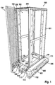
- FIG. 1 shows an exemplary embodiment of a stabilizer assembly for the transport of a cabinet 100.
- the cabinet 100 has a frame 101 of vertical and horizontal struts, wherein on a door side 102 of the frame 101 via three hinges 103, a cabinet door 104 is attached.
- the cabinet door 104 is thus between an open position in which it is pivoted from the door side 102 (as shown), and a closed position in which it rests against the door side 102 (see FIGS. 6 and 7 ), pivotable back and forth.
- the form-fitting pieces 200 are for this purpose in particular attached to a vertical profile side of the horizontal struts of the door 102, for example screwed via a system perforation of regularly spaced mounting receptacles with the profile side.
- a respective form-fitting piece 200 is arranged in each case in one of the four corners of the door side 102, or along the horizontal profiles of the door side 102 upstream of their respective corner.
- the frame 101 further comprises a rectangular bottom frame 109 of four horizontal struts.
- One of the horizontal struts namely the horizontal strut designated by the reference numeral 110, is arranged in the door side 102.
- One of the arranged in the door 102 side horizontal strut 110 opposite further horizontal strut of the bottom frame 109 is disposed in the rear wall side of the frame 101.
- About the horizontal struts 110 in the door 102 and in the Rear wall side are each attached two brackets 111 via a mounting flange 112 which lies in the door 102 side.
- At each of the two brackets 111, in particular on the respective mounting flange 112, one of the form-locking pieces 200 is attached.
- the cabinet 100 is attached to two Gleitboards 300 below the bottom frame 109.
- the bottom frame 109 is placed over the four brackets 111 at a distance from the Gleitboards 300 on a transportable with a forklift transport pallet 400.
- the bottom frame has at each of its four corners formed as L-angle bracket 111, via which the cabinet is attached to one of four Gleitboards.
- the distance under which the bottom frame 109 is attached to the slide boards 300 corresponds to a vertical dimension of a cabinet base.
- the brackets 111 are fixed to a vertical side of the floor frame 109 and extending away from the cabinet 100 with their tread flange 113, so that a tread side of the floor frame 109 for mounting a cabinet base on the tread side is completely exposed.
- the transport pallet 400 has an enclosure 401, which surrounds the Gleitboards 300 and thus keeps the control cabinet 100 on the transport pallet 400 in the horizontal direction or in the plane of the footprint of the transport pallet 400 immovably with tilted pallet. As in FIG. 2 is shown, this particular allows for the transport of the cabinet with a forklift 500 that the cabinet with its usual installations (mounting plate, etc.) can be tilted up to an edge height of about 20 cm, without thereby displaced on the transport pallet 400. Due to the engaging in the form-fitting receptacles 105 form-fitting 200, can be counteracted in tilting the cabinet 100 in the closed position of the cabinet door 104 twisting of the frame 101.
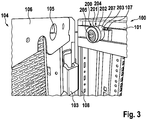
- FIG. 2 and 3 is a first form-fitting 200 shown in a mounting situation on the roof frame of a control cabinet 100.
- the profile struts of the roof frame have a in the closed position of the cabinet door 104 of the cabinet door 104 facing support 107 on which the interlocking piece 200 rests with a projection 207 and is thus aligned in the vertical direction relative to the frame 101.
- the cabinet door 104 has on its outer periphery a U-Umkantung 106, which is folded over from the door leaf of the cabinet door 104 to the inside of the cabinet door 104.
- a positive connection receptacle 105 is formed in the form of a circular opening, in which the interlocking piece 200 engages with its free end 201 in the closed position of the cabinet door 104.
- the free end 201 passes over an undercut 202 in a shaft-shaped portion 203 of the form-fitting 200 over.
- the projection 207 extends beyond a bearing surface of the shaft 203, via which the shaft 203 rests against a vertical profile side of the frame 101, in particular of the roof frame.
- the form-fitting piece 200 is embodied in two parts and, in addition to a body 204 having the free end 201, the undercut 202 and the shank 203, a fastening means 205 in the form of a screw bolt, via which the body 204 can be screwed to the frame 101.
- the frame 101 may for this purpose in particular have an arrangement of regularly spaced mounting receptacles. For example, a cage nut may be inserted into one of the fastening receptacles for the screw connection.
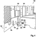
- FIGS. 4 and 5 a further embodiment of a form-fitting piece 200 is shown, which is screwed in the region of a bottom frame of the frame 101 in the corner region of the bottom frame.
- Analogous to that in the Figures 3 and 4 also shown the form-fitting 200 according to the FIGS. 4 and 5 a free end 201 with a start-up contour, which merges via an undercut 202 into a shaft 203.
- the fastening means is integrally formed integrally with the shank 203, concentric with the shank 203, and may in particular be designed in the manner of a threaded bolt.
- the positive connection 105 is analogous to those in Figures 3 and 4 Shaped receptacles shown in turn formed as a circular breakthrough in a U-Umkantung 106 on the outer periphery of a cabinet door 104.
- the free end 201 Concentric with the threaded bolt 205, the free end 201 has a tool holder, for example a hexagon socket.
- the hexagon socket can be identical to the hexagon of the fastener 205 of the in the Figures 2 and 3 be formed shown two-part embodiment.
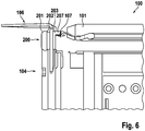
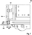
- FIGS. 6 and 7 each show a cabinet 100, in which the cabinet door 104 is disposed in the closed position While the FIG. 6 shows the cabinet 100 in the roof frame is in the FIG. 7 the control cabinet is shown in the area of the floor frame.
- the interlock 200 extends with its free end 201 through a vertical flange of the U-Umkantung 106 therethrough, at least so far that the vertical flange of the U-Umkantung is engaged behind by the undercut 202 of the form-fitting.
- the outer diameter of the interlocking piece 200 may be less than the inner diameter of the positive locking receptacle 105 (see FIGS. 2 to 5 ), so that the stabilization arrangement under load of the frame, such as when tilting the cabinet, as in FIG. 12 is shown, a certain maximum distortion of the frame 101 allows before further connection on further loading of the frame 101 due to the recorded in the form-fitting receptacles 105 form-fitting 200 is prevented.
- FIGS. 8 and 9 a first embodiment of the form-fitting 200 is shown.
- the form-fitting piece 200 has a free end 201, which merges via an undercut 202 into a shaft 203.
- the free end 201, the undercut 202 and the shaft 203 form a body 204 which has an eccentric through bore 206 eccentric to the axis of symmetry of the interlocking fitment 200.
- a projection 207 extends, as with reference to Figures 2 and 3 shown embodiment on a corresponding horizontal support of the frame comes to rest in order to prepare the interlock 200 in the vertical orientation.
- An attachment means 205 in the form of a threaded bolt is provided to extend through the throughbore 206 into a frame of a cabinet, where the threaded bolt 205 may, for example, be screwed into a cage nut and thus secure the body 204 to the frame.
- FIGS. 10 and 11 show a further embodiment of a form-fitting 200, which deviates from that in the FIGS. 8 and 9 shown form-fitting 200 is formed in particular in one piece.
- the free end 201 is provided with a start-up contour, which should facilitate the pivoting of the cabinet door in the closed position, for example, if due to manufacturing tolerances, the positive connection receptacle on the inside of the door and the form-fitting 200 are not exactly aligned with each other at their meeting.
- the free end 201 in turn via an undercut 202 in a shaft-shaped portion 203 via. Concentric with the shaft-shaped portion 203, a threaded bolt 205 is formed on a support side of the shaft 203, via which the interlocking piece 200 can be brought to a frame for conditioning.
Landscapes
- Engineering & Computer Science (AREA)
- Power Engineering (AREA)
- Microelectronics & Electronic Packaging (AREA)
- Manufacturing & Machinery (AREA)
- Mechanical Engineering (AREA)
- Patch Boards (AREA)
- Assembled Shelves (AREA)
Abstract
Description
- Die Erfindung geht aus von einer Stabilisierungsanordnung für den Transport eines Schaltschranks, mit einem Schaltschrank, der ein Rahmengestell aus Vertikal- und Horizontalstreben aufweist, und mit einer an einer Türseite des Rahmengestells über mindestens ein Scharnier befestigten Schaltschranktür, so dass die Schaltschranktür zwischen einer Offenposition, in der sie von der Türseite abgeschwenkt ist, und einer Schließposition, in der sie an der Türseite anliegt, hin und her schwenkbar ist. Aus der
CN 204425828 U ist Stabilisierungsanordnung bekannt, bei der das Schaltschrankrahmengestell durch eine Versteifungsstruktur zusätzlich verstärkt ist. Ähnliche Anordnungen zeigen auch dieDE 102 02 845 C1 und dieDE 196 15 430 C1 . - Die aus dem Stand der Technik bekannten Stabilisierungsanordnungen haben den Nachteil, dass sie konstruktiv aufwendig gestaltet sind und zum Teil einen erheblichen Materialaufwand bedingen. So ist bei der
CN 204425828 U beispielsweise vorgesehen, dass die Rückwand des Schrankschranks doppelwandig ausgebildet ist, um dem Schaltschrank Stabilität zu verleihen. - Es ist daher die Aufgabe der Erfindung, eine Stabilisierungsanordnung der eingangs beschriebenen Art derart weiterzuentwickeln, dass sie mit technisch einfachen Mitteln und damit kostengünstig zur Verfügung gestellt werden kann. Die Stabilisierungsanordnung sollte weiterhin derart ausgestaltet sein, dass die zur Stabilisierung vorgesehenen Mittel nach dem Transport, das heißt nachdem das Schaltschrankgehäuse seine endgültige Position erreicht hat, leicht entfernt werden können.
- Diese Aufgabe wird durch eine Stabilisierungsanordnung mit den Merkmalen des Anspruchs 1 gelöst. Die abhängigen Ansprüche betreffen jeweils vorteilhafte Ausführungsformen der Erfindung.
- Demgemäß ist vorgesehen, dass an der Türseite mindestens ein Formschlussstück befestigt ist, das sich mit seinem freien Ende von der Türseite weg erstreckt und an seinem freien Ende einen Hinterschnitt aufweist, wobei die Schaltschranktür, vorzugsweise an ihrer in der Schließstellung der Türseite zugewandten Innenseite, eine Formschlussaufnahme aufweist, in die in der Schließstellung das Formschlussstück mit seinem freien Ende hineinragt und die von dem Hinterschnitt in der Schließstellung hintergriffen ist.
- Bei der beschriebenen Stabilisierungsanordnung wird somit die Schaltschranktür während des Transports des Schaltschranks über das in die Formschlussaufnahme der Schaltschranktür eingreifende Formschlussstück des Rahmengestells gegenüber dem Rahmengestell stabilisiert, so dass die Schaltschranktür im Transportfall die Zusatzfunktion aufweist, das Rahmengestell in sich zu stabilisieren. Die Stabilisierung kann verbessert werden, indem mehrere Paare aus einer Formschlussaufnahme und einem darin eingreifenden Formschlussstück vorgesehen sind, beispielsweise diametral gegenüber liegend. Funktional betrachtet hat die Schaltschranktür bei diametral gegenüber liegenden Paaren aus einer Formschlussaufnahme und einem darin eingreifenden Formschlussstück die Wirkung einer sich in der Türseite quer erstreckenden Versteifungsstrebe.
- Die Formschlussstücke können als einteilige oder mehrteilige Kunststoff- oder Metallformteile ausgebildet sein, die mit dem Rahmengestell des Schaltschranks über die Türseite des Rahmengestells bedarfsweise verschraubt oder anderweitig lösbar verbunden werden können. Dazu kann beispielsweise vorgesehen sein, dass die Formschlussstücke über die in gängigen Rahmengestellen ohnehin vorhandene Systemlochung aus regelmäßig beabstandeten Befestigungsaufnahmen festgelegt werden. Dazu kann beispielsweise in einer der Befestigungsaufnahmen eine Einsteckmutter mit einem Innengewinde angeordnet werden, während das Formschlussstück einen Gewindebolzen aufweist, mit dem es in die Einsteckmutter eingeschraubt und damit an dem Rahmengestell festgelegt wird.
- Das freie Ende des Formschlussstücks kann in Richtung zur Erstreckungsrichtung des Formschlussstücks eine maximale Abmessung aufweisen, die einer Innenabmessung der Formschlussaufnahme entspricht. Das freie Ende kann weiterhin eine Anlaufkontur aufweisen, entlang welcher sich das Formschlussstück von seiner Stirnseite auf die maximale Abmessung aufweitet. Beim Zuschwenken der Schaltschranktür wird somit auch dann eine sichere Einführung des freien Endes in die Formschlussaufnahme der Schaltschranktür gewährleistet, wenn beispielsweise aufgrund von Fertigungstoleranzen bei dem Aufeinandertreffen von Formschlussaufnahme und Formschlussstück die beiden nicht exakt fluchten.
- Das freie Ende kann in Erstreckungsrichtung des Formschlussstücks an dem Hinterschnitt in einen Schacht des Formschlussstücks übergehen, über den das Formschlussstück an der Türseite festgelegt ist. Der Schaft kann in Richtung senkrecht zur Erstreckungsrichtung des Formschlussstücks eine maximale Abmessung aufweisen, die kleiner als eine Innenabmessung der Formschlussaufnahme ist. Es ist insbesondere nicht erforderlich, dass der Schaft formschlüssig in der Formschlussaufnahme aufgenommen ist. Die Funktion der Stabilisierungsanordnung kann bereits dadurch erfüllt sein, dass beispielsweise während des Transportes des Schaltschranks auftretende Verwindungen des Schaltschrankrahmengestells auf ein bestimmtes (geringes) maximal zugelassenes Maß beschränkt werden.
- Die Formschlussaufnahme kann ein Durchbruch in einer U-Umkantung am Außenumfang der Schaltschranktür sein. Die U-Umkantung kann insbesondere eine Umkantung am Außenumfang des Türblatts der Schaltschranktür sein. Dabei kann das Türblatt zur Türinnenseite U-förmig umgekantet sein. In der Schließstellung kann somit das freie Ende zwischen den beiden parallel zueinander beabstandeten Flanschen der U-Umkantung aufgenommen sein.
- Das Formschlussstück kann einen Korpus und ein Befestigungsmittel aufweisen, das den Korpus an der Türseite unbeweglich festlegt. Der Korpus weist das freie Ende und einen daran über den Hinterschnitt angrenzenden Schaft auf, über den das Formschlussstück an die Türseite angrenzt, insbesondere an dem Rahmengestell anliegt.
- Der Korpus und das Befestigungsmittel können als separate Bauteile ausgebildet sein. Dabei kann der Korpus eine Durchgangsbohrung aufweisen, über die der Korpus mit dem Befestigungsmittel, insbesondere mit einem Schraubbolzen, an der Türseite festgelegt ist.
- Die Durchgangsbohrung kann sich dabei exzentrisch und parallel zu einer Symmetrieachse des Korpus durch den Korpus erstrecken, wobei der Schaft an seinem der Türseite zugewandten Ende einen Vorsprung aufweist, der ebenfalls exzentrisch zu der Symmetrieachse des Korpus, jedoch in Bezug auf die Symmetrieachse gegenüber der Durchgangsbohrung angeordnet ist, und wobei der Schaft mit dem Vorsprung auf einer horizontalen Auflage des Rahmengestells aufliegt.
- Der Korpus und das Befestigungsmittel können auch einteilig ausgebildet sein, wobei sich das Befestigungsmittel, insbesondere ein Schraubbolzen, konzentrisch zu dem Schaft erstreckt und an ein der Türseite zugewandtes Ende des Schafts angeformt ist.
- Die Türseite kann einen rechteckigen Profilrahmen aufweisen, wobei an dem Profilrahmen zwei der Formschlussstücke diametral gegenüberliegend angeordnet sind.
- Dabei können an dem Profilrahmen zwei Paare Formschlussstücke angeordnet sein, von denen die beiden Formschlusstücke eines ersten der Paare und die beiden Formschlussstücke eines zweiten der Paare jeweils diametral gegenüberliegend, insbesondere in diametral gegenüberliegenden Eckbereichen des Profilrahmens, angeordnet sind.
- Das Rahmengestell kann einen rechteckigen Bodenrahmen aus vier Horizontalstreben aufweisen, von denen eine Horizontalstrebe in der Türseite liegt und an dieser Horizontalstrebe mindestens ein Haltewinkel über einen Befestigungsflansch des Haltewinkels montiert ist, der in der Türseite liegt, wobei an dem Befestigungsflansch das mindestens eine Formschlussstück festgelegt ist, und vorzugsweise der Befestigungsflansch über einen Gewindebolzen des Formschlussstücks an der Horizontalstrebe festgelegt ist.
- Der Schaltschrank kann über den mindestens einen Haltewinkel an mindestens einem Gleitboard unterhalb des Bodenrahmens befestigt sein, wobei der Bodenrahmen über den mindestens einen Haltewinkel unter einem Abstand zu dem mindestens einen Gleitboard auf einer mit einem Gabelstapler unterfahrbaren Transportpalette aufsteht.
- Der Bodenrahmen kann an jeder seiner vier Ecken einen als L-Winkel ausgebildeten Haltewinkel aufweisen, über den der Schaltschrank an einem Gleitboard befestigt ist, wobei der Abstand, unter dem der Bodenrahmen zu dem mindestens einen Gleitboard an dem Gleitboard befestigt ist, einer vertikalen Abmessung eines Schaltschranksockels entspricht, und wobei die Haltewinkel an einer Vertikalseite des Bodenrahmens und sich mit ihrem Aufstandsflansch von dem Schaltschrank weg erstreckend befestigt sind, so dass eine Aufstandsseite des Bodenrahmens für die Montage eines Schaltschranksockels an der Aufstandsseite vollständig freiliegt. Entsprechende Haltewinkel können an einer weiteren Horizontalstrebe des Bodenrahmens befestigt sein, die der Horizontalstrebe, die in der Türseite liegt, gegenüber angeordnet ist, insbesondere in einer Rückwandseite des Rahmengestells.
- Die Transportpalette kann eine Einfassung aufweisen, die das mindestens eine Gleitboard umrandet, so dass der Schaltschrank auf der Transportpalette in Horizontalrichtung bzw. bei gekippter Palette in der Ebene einer Aufstandsfläche der Palette unverrückbar ist.
- Weitere Einzelheiten der Erfindung werden anhand der nachstehenden Figuren erläutert. Dabei zeigt:
- Figur 1
- in perspektivischer Darstellung eine beispielshafte Ausführungsform einer Stabilisierungsanordnung;
- Figur 2
- in perspektivischer Darstellung den Eckbereich eines Schaltschranks einer Stabilisierungsanordnung gemäß einer Ausführungsform in einer Explosionsdarstellung des Formschlussstücks;
- Figur 3
- die Ausführungsform und Ansicht gemäß
Figur 2 , wobei das Formschlussstück in der vollständig montierten Position gezeigt ist; - Figur 4
- in perspektivischer Darstellung den Eckbereich einer weiteren Ausführungsform der Erfindung, wobei das Formschlussstück in einer von dem Schaltschrank demontierten Stellung gezeigt ist;
- Figur 5
- die Ausführungsform und Ansicht gemäß
Figur 4 , wobei das Formschlussstück an dem Schaltschrankrahmen montiert ist; - Figur 6
- eine Seitenansicht des Eckbereichs einer Ausführungsform einer erfindungsgemäßen Stabilisierungsanordnung im Dachbereich des Schaltschranks;
- Figur 7
- die Ausführungsform gemäß
Figur 6 , wobei der Eckbereich des Bodenrahmens des Schaltschranks gezeigt ist; - Figur 8
- eine erste Ausführungsform eines Formschlussstücks;
- Figur 9
- eine Querschnittsansicht des Korpus der Ausführungsform gemäß
Figur 8 ; - Figur 10
- in perspektivischer Darstellung eine weitere Ausführungsform eines Formschlussstücks;
- Figur 11
- eine Querschnittsansicht der Ausführungsform gemäß
Figur 10 ; und - Figur 12
- eine beispielhafte Transportsituation unter Verwendung einer erfindungsgemäßen Stabilisierungsanordnung.
- Die
Figur 1 zeigt eine beispielhafte Ausführungsform einer Stabilisierungsanordnung für den Transport eines Schaltschranks 100. Der Schaltschrank 100 weist ein Rahmengestell 101 aus Vertikal- und Horizontalstreben auf, wobei an einer Türseite 102 des Rahmengestells 101 über drei Scharniere 103 eine Schaltschranktür 104 befestigt ist. Die Schaltschranktür 104 ist so zwischen einer Offenposition, in der sie von der Türseite 102 abgeschwenkt ist (wie dargestellt), und einer Schließposition, in der sie an der Türseite 102 anliegt (vergleicheFiguren 6 und7 ), hin und her schwenkbar. - An der Türseite 102 sind vier Formschlussstücke 200 befestigt, die sich mit ihren freien Enden 201 von der Türseite 102 weg erstrecken. Die Formschlussstücke 200 sind dazu insbesondere an einer vertikalen Profilseite der Horizontalstreben der Türseite 102 befestigt, beispielsweise über eine Systemlochung aus regelmäßig beabstandeten Befestigungsaufnahmen mit der Profilseite verschraubt. Insbesondere ist jeweils ein Formschlussstück 200 in einer der vier Ecken der Türseite 102, beziehungsweise entlang der Horizontalprofile der Türseite 102 ihrer jeweiligen Ecke vorgelagert angeordnet.
- Das Rahmengestell 101 weist weiterhin einen rechteckigen Bodenrahmen 109 aus vier Horizontalstreben auf. Eine der Horizontalstreben, nämlich die mit dem Bezugszeichen 110 gekennzeichnete Horizontalstrebe ist in der Türseite 102 angeordnet. Eine der in der Türseite 102 angeordneten Horizontalstrebe 110 gegenüberliegende weitere Horizontalstrebe des Bodenrahmens 109 ist in der Rückwandseite des Rahmengestells 101 angeordnet. Über die Horizontalstreben 110 in der Türseite 102 und in der Rückwandseite sind jeweils zwei Haltewinkel 111 über einen Befestigungsflansch 112 befestigt, der in der Türseite 102 liegt. An jedem der beiden Haltewinkel 111, insbesondere an dem jeweiligen Befestigungsflansch 112, ist eines der Formschlussstücke 200 befestigt. Über die Haltewinkel 111 ist der Schaltschrank 100 an zwei Gleitboards 300 unterhalb des Bodenrahmens 109 befestigt. Insbesondere ist der Bodenrahmen 109 über die vier Haltewinkel 111 unter einem Abstand zu den Gleitboards 300 auf einer mit einem Gabelstapler unterfahrbaren Transportpalette 400 aufgesetzt.
- Insbesondere weist der Bodenrahmen an jeder seiner vier Ecken als L-Winkel ausgebildete Haltewinkel 111 auf, über die der Schaltschrank an einem von vier Gleitboards befestigt ist. Der Abstand, unter dem der Bodenrahmen 109 zu den Gleitboards 300 befestigt ist, entspricht einer vertikalen Abmessung eines Schaltschranksockels. Die Haltewinkel 111 sind an einer Vertikalseite des Bodenrahmens 109 und sich mit ihrem Aufstandsflansch 113 von dem Schaltschrank 100 weg erstreckend befestigt, so dass eine Aufstandsseite des Bodenrahmens 109 für die Montage eines Schaltschranksockels an der Aufstandsseite vollständig freiliegt.
- Die Transportpalette 400 weist eine Einfassung 401 auf, die die Gleitboards 300 umrandet und somit den Schaltschrank 100 auf der Transportpalette 400 in der Horizontalrichtung beziehungsweise in der Ebene der Aufstandsfläche der Transportpalette 400 bei gekippter Palette unverrückbar hält. Wie in
Figur 2 gezeigt ist, ermöglicht dies insbesondere für den Transport des Schaltschranks mit einem Gabelstapler 500, dass der Schaltschrank mit seinen üblichen Einbauten (Montageplatte, usw.) bis zu einer Kantenhöhe von ungefähr 20 cm geneigt werden kann, ohne dadurch auf der Transportpalette 400 zu verrücken. Aufgrund der in die Formschlussaufnahmen 105 eingreifenden Formschlussstücke 200, kann in der Schließstellung der Schaltschranktür 104 einer Verwindung des Rahmengestells 101 beim Verkippen des Schaltschranks 100 entgegengewirkt werden. - In den
Figuren 2 und3 ist ein erstes Formschlussstück 200 in einer Einbausituation am Dachrahmen eines Schaltschranks 100 dargestellt. Die Profilstreben des Dachrahmens weisen eine in der Schließstellung der Schaltschranktür 104 der Schaltschranktür 104 zugewandte Auflage 107 auf, auf der das Formschlussstück 200 mit einem Vorsprung 207 aufliegt und somit in der Vertikalrichtung gegenüber dem Rahmengestell 101 ausgerichtet ist. - Die Schaltschranktür 104 weist an ihrem Außenumfang eine U-Umkantung 106 auf, die von dem Türblatt der Schaltschranktür 104 zur Innenseite der Schaltschranktür 104 umgekantet ist. In einem parallel beabstandet zu dem Türblatt angeordneten Flansch der U-Umkantung 106 ist eine Formschlussaufnahme 105 in Form eines kreisförmigen Durchbruchs ausgebildet, in welchen das Formschlussstück 200 mit seinem freien Ende 201 in der Schließstellung der Schaltschranktür 104 eingreift. Das freie Ende 201 geht über einen Hinterschnitt 202 in einen schaftförmigen Abschnitt 203 des Formschlussstücks 200 über. Der Vorsprung 207 erstreckt sich über eine Auflagefläche des Schafts 203 hinaus, über welche der Schaft 203 an einer vertikalen Profilseite des Rahmengestells 101, insbesondere des Dachrahmens, anliegt.
- Das Formschlussstück 200 ist zweiteilig ausgeführt und weist neben einem das freie Ende 201, den Hinterschnitt 202 und den Schaft 203 aufweisenden Korpus 204 ein Befestigungsmittel 205 in Form eines Schraubbolzens auf, über den der Korpus 204 an dem Rahmengestell 101 verschraubt werden kann. Das Rahmengestell 101 kann dazu insbesondere eine Anordnung aus regelmäßig beabstandeten Befestigungsaufnahmen aufweisen. Für die Verschraubung kann in eine der Befestigungsaufnahmen beispielsweise eine Käfigmutter eingesetzt sein.
- In den
Figuren 4 und5 ist eine weitere Ausführungsform eines Formschlussstücks 200 gezeigt, welches im Bereich eines Bodenrahmens des Rahmengestells 101 im Eckbereich des Bodenrahmens verschraubt ist. Analog zu dem in denFiguren 3 und4 gezeigten Formschlussstück 200 weist auch das Formschlussstück 200 gemäß denFiguren 4 und5 ein freies Ende 201 mit einer Anlaufkontur auf, die über einen Hinterschnitt 202 in einen Schaft 203 übergeht. An dem dem freien Ende 201 gegenüberliegenden Ende des Schafts 203 ist konzentrisch zu dem Schaft 203 das Befestigungsmittel einteilig an den Schaft 203 angeformt und kann insbesondere nach Art eines Gewindebolzens ausgebildet sein. - Die Formschlussaufnahme 105 ist analog zu den in
Figuren 3 und4 gezeigten Formschlussaufnahmen wiederum als ein kreisförmiger Durchbruch in einer U-Umkantung 106 am Außenumfang einer Schaltschranktür 104 ausgebildet. Konzentrisch zu dem Gewindebolzen 205 weist das freie Ende 201 eine Werkzeugaufnahme auf, beispielsweise einen Innensechskant. Der Innensechskant kann identisch zu dem Innensechskant des Befestigungsmittels 205 der in denFiguren 2 und3 gezeigten zweiteiligen Ausführungsform ausgebildet sein. - Die
Figuren 6 und7 zeigen jeweils einen Schaltschrank 100, bei dem die Schaltschranktür 104 in der geschlossenen Position angeordnet ist Während dieFigur 6 den Schaltschrank 100 im Bereich des Dachrahmens zeigt, ist in derFigur 7 der Schaltschrank im Bereich des Bodenrahmens gezeigt. In der gezeigten Schließposition erstreckt sich das Formschlussstück 200 mit seinem freien Ende 201 durch einen vertikalen Flansch der U-Umkantung 106 hindurch, zumindest so weit, dass der vertikalen Flansch der U-Umkantung von dem Hinterschnitt 202 des Formschlussstücks hintergriffen ist. Im Bereich des Schaftes 203, mit welchem das Formschlussstück 200 durch den Flansch der U-Umkantung 106 hindurchragt, kann der Außendurchmesser des Formschlussstücks 200 geringer sein als der Innendurchmesser der Formschlussaufnahme 105 (vergleicheFiguren 2 bis 5 ), so dass die Stabilisierungsanordnung bei Belastung des Rahmengestells, etwa beim Verkippen des Schaltschranks, wie dies inFigur 12 gezeigt ist, eine gewisse maximale Verwindung des Rahmengestells 101 zulässt, bevor eine weitere Verbindung bei weiterer Belastung des Rahmengestells 101 aufgrund der in den Formschlussaufnahmen 105 aufgenommene Formschlussstücke 200 verhindert wird. - In den
Figuren 8 und 9 ist eine erste Ausführungsform des Formschlussstücks 200 gezeigt. Das Formschlussstück 200 weist ein freies Ende 201, das über einen Hinterschnitt 202 in einen Schaft 203 übergeht. Das freie Ende 201, der Hinterschnitt 202 und der Schaft 203 bilden einen Korpus 204, der eine zur Symmetrieachse des Formschlussstücks 200 exzentrische Durchgangsbohrung 206 aufweist. Von einer der Stirnseite des freien Endes 201 gegenüber angeordneten Rückseite des Formschlussstücks, welche gleichzeitig eine Anlagefläche des Schaftes 203 bildet, über welche das Formschlussstück 200 an dem Rahmengestell eines Schaltschranks zur Anlage kommt, erstreckt sich ein Vorsprung 207 der, wie mit Bezug auf die inFiguren 2 und3 gezeigte Ausführungsform auf einer entsprechenden horizontalen Auflage des Rahmengestells zur Anlage kommt, um das Formschlussstück 200 in der Vertikalausrichtung vorauszurichten. Ein Befestigungsmittel 205 in Form eines Gewindebolzens ist dazu vorgesehen, sich durch die Durchgangsbohrung 206 bis in ein Rahmengestell eines Schaltschranks hinein zu erstrecken, wo der Gewindebolzen 205 beispielsweise in eine Käfigmutter eingeschraubt sein kann und somit den Korpus 204 an dem Rahmengestell festlegt. - Die
Figuren 10 und 11 zeigen eine weitere Ausführungsform eines Formschlussstücks 200, welches abweichend von dem in denFiguren 8 und 9 gezeigten Formschlussstück 200 insbesondere einteilig ausgebildet ist. Wie auch bei dem in denFiguren 8 und 9 gezeigten Formschlussstück 200 ist das freie Ende 201 mit einer Anlaufkontur versehen, welche das Zuschwenken der Schaltschranktür in die Schließposition erleichtern soll, wenn beispielsweise aufgrund von Fertigungstoleranzen die Formschlussaufnahme an der Türinnenseite und das Formschlussstück 200 bei ihrem Aufeinandertreffen nicht exakt miteinander fluchten. Das freie Ende 201 geht wiederum über einen Hinterschnitt 202 in einen schaftförmigen Abschnitt 203 über. Konzentrisch zu dem schaftförmigen Abschnitt 203 ist ein Gewindebolzen 205 an eine Auflageseite des Schafts 203 angeformt, über den das Formschlussstück 200 an einem Rahmengestell zur Anlage gebracht werden kann. - Die in der vorstehenden Beschreibung, in den Zeichnungen sowie in den Ansprüchen offenbarten Merkmale der Erfindung können sowohl einzeln als auch in beliebiger Kombination für die Verwirklichung der Erfindung wesentlich sein.
-
- 100
- Schaltschrank
- 101
- Rahmengestell
- 102
- Türseite
- 103
- Scharnier
- 104
- Schaltschranktür
- 105
- Formschlussaufnahme
- 106
- U-Umkantung
- 107
- Auflage
- 108
- Profilrahmen
- 109
- Bodenrahmen
- 110
- Horizontalstrebe
- 111
- Haltewinkel
- 112
- Befestigungsflansch
- 113
- Aufstandsflansch
- 200
- Formschlussstück
- 201
- freies Ende
- 202
- Hinterschnitt
- 203
- Schaft
- 204
- Korpus
- 205
- Befestigungsmittel
- 206
- Durchgangsbohrung
- 207
- Vorsprung
- 300
- Gleitboard
- 400
- Transportpalette
- 401
- Einfassung
- 500
- Gabelstapler
- 600
- Verpackung
- h
- Höhe
Claims (15)
- Stabilisierungsanordnung für den Transport eines Schaltschranks (100), mit einem Schaltschrank (100), der ein Rahmengestell (101) aus Vertikal- und Horizontalstreben aufweist, und mit einer an einer Türseite (102) des Rahmengestells (101) über mindestens ein Scharnier (103) befestigten Schaltschranktür (104), so dass die Schaltschranktür (104) zwischen einer Offenposition, in der sie von der Türseite (102) abgeschwenkt ist, und einer Schließposition, in der sie an der Türseite (102) anliegt, hin und her schwenkbar ist, dadurch gekennzeichnet, dass an der Türseite (102) mindestens ein Formschlussstück (200) befestigt ist, das sich mit seinem freien Ende (201) von der Türseite (102) weg erstreckt und an seinem freien Ende (201) einen Hinterschnitt (202) aufweist, wobei die Schaltschranktür (104) eine Formschlussaufnahme (105) aufweist, in die in der Schließstellung das Formschlussstück (200) mit seinem freien Ende (201) hinein ragt und die von dem Hinterschnitt (202) in der Schließstellung hintergriffen ist.
- Stabilisierungsanordnung nach Anspruch 1, bei der das freie Ende (201) in Richtung senkrecht zur Erstreckungsrichtung des Formschlussstücks (200) eine maximale Abmessung aufweist, die einer Innenabmessung der Formschlussaufnahme (105) entspricht.
- Stabilisierungsanordnung nach Anspruch 1 oder 2, bei der das freie Ende (201) in Erstreckungsrichtung des Formschlussstücks (200) an dem Hinterschnitt (202) in einen Schaft (203) des Formschlussstücks (200) übergeht, über den das Formschlussstück (200) an der Türseite (102) festgelegt ist.
- Stabilisierungsanordnung nach Anspruch 3, bei der der Schaft (203) in Richtung senkrecht zur Erstreckungsrichtung des Formschlussstücks (200) eine maximale Abmessung aufweist, die kleiner als eine Innenabmessung der Formschlussaufnahme (105) ist.
- Stabilisierungsanordnung nach einem der vorangegangenen Ansprüche, bei der die Formschlussaufnahme (105) ein Durchbruch in einer U-Umkantung (106) am Außenumfang der Schaltschranktür (104) ist.
- Stabilisierungsanordnung nach einem der vorangegangenen Ansprüche, bei der das Formschlussstück (200) einen Korpus (204), der das freie Ende (201) und einen daran über den Hinterschnitt (202) am Außenumfang des Formschlussstücks (200) angrenzenden Schaft (203) aufweist, über den das Formschlussstück (200) an die Türseite (102) angrenzt, und ein Befestigungsmittel (205) aufweist, das den Korpus (204) an der Türseite (102) unbeweglich festlegt.
- Stabilisierungsanordnung nach Anspruch 6, bei der der Korpus (204) und das Befestigungsmittel (205) als separate Bauteile ausgebildet sind und der Korpus (204) eine Durchgangsbohrung (206) aufweist, über die der Korpus (204) mit dem Befestigungsmittel (205), insbesondere einem Schraubbolzen, an der Türseite (102) festgelegt ist.
- Stabilisierungsanordnung nach Anspruch 7, bei der der sich die Durchgangsbohrung (206) exzentrisch und parallel zu einer Symmetrieachse des Korpus (204) durch den Korpus (204) erstreckt, wobei der Schaft (203) an seinem der Türseite (102) zugewandten Ende einen Vorsprung (207) aufweist, der ebenfalls exzentrisch zu der Symmetrieachse des Korpus (204), jedoch in Bezug auf die Symmetrieachse gegenüber der Durchgangsbohrung (206) angeordnet ist, und wobei der Schaft (203) mit dem Vorsprung (207) auf einer horizontalen Auflage (107) des Rahmengestells (101) aufliegt.
- Stabilisierungsanordnung nach Anspruch 6, bei der der Korpus (204) und das Befestigungsmittel (205) einteilig ausgebildet sind, wobei sich das Befestigungsmittel (205), insbesondere ein Schraubbolzen, konzentrisch zu dem Schaft (203) erstreckt und an ein der Türseite (102) zugewandtes Ende des Schafts (203) angeformt ist.
- Stabilisierungsanordnung nach einem der vorangegangenen Ansprüche, bei der die Türseite (102) einen rechteckigen Profilrahmen (108) aufweist, wobei an dem Profilrahmen (108) zwei der Formschlussstücke (200) diametral gegenüber liegend angeordnet sind.
- Stabilisierungsanordnung nach Anspruch 10, bei der an dem Profilrahmen (108) zwei Paare Formschlussstücke (200) angeordnet sind, von denen die beiden Formschlussstücke (200) eines ersten der Paare und die beiden Formschlussstücke (200) eines zweiten der Paare jeweils diametral gegenüber liegend, insbesondere in diametral gegenüber liegenden Eckbereichen des Profilrahmens (108), angeordnet sind.
- Stabilisierungsanordnung nach einem der vorangegangenen Ansprüche, bei der das Rahmengestell (101) einen rechteckigen Bodenrahmen (109) aus vier Horizontalstreben aufweist, von denen eine Horizontalstrebe (110) in der Türseite (102) liegt und an dieser Horizontalstrebe (110) mindestens ein Haltewinkel (111) über einen Befestigungsflansch (112) des Haltewinkels (111) montiert ist, der in der Türseite (102) liegt, wobei an dem Befestigungsflansch (112) das mindestens eine Formschlussstück (200) und vorzugsweise der Befestigungsflansch (112) über einen Gewindebolzen des Formschlussstücks (200) an der Horizontalstrebe (110) festgelegt sind.
- Stabilisierungsanordnung nach Anspruch 12, bei der der Schaltschrank (100) über den mindestens einen Haltewinkel (111) an mindestens einem Gleitboard (300) unterhalb des Bodenrahmens (109) befestigt ist, wobei der Bodenrahmen (109) über den mindestens einen Haltwinkel (111) unter einem Abstand zu dem mindestens einen Gleitboard (300) auf einer mit einem Gabelstapler (500) unterfahrbaren Transportpalette (400) aufsteht.
- Stabilisierungsanordnung nach Anspruch 13, bei der der Bodenrahmen (109) an jeder seiner vier Ecken einen als L-Winkel ausgebildeten Haltewinkel (111) aufweist, über den der Schaltschrank (100) an einem Gleitboard (300) befestigt ist, wobei der Abstand, unter dem der Bodenrahmen (109) zu dem mindestens einen Gleitboard (300) an dem Gleitboard (300) befestigt ist, einer vertikalen Abmessung eines Schaltschranksockels entspricht, und wobei die Haltewinkel (111) an einer Vertikalseite des Bodenrahmens (109) und sich mit ihrem Aufstandsflansch (113) von dem Schaltschrank (100) weg erstreckend befestigt sind, so dass eine Aufstandsseite des Bodenrahmens (109) für die Montage eines Schaltschranksockels an der Aufstandsseite vollständig frei liegt.
- Stabilisierungsanordnung nach Anspruch 13 oder 14, bei der die Transportpalette (400) eine Einfassung (401) aufweist, die das mindestens eine Gleitboard (300) umrandet, so dass der Schaltschrank (100) auf der Transportpalette (400) in Horizontalrichtung unverrückbar ist.
Priority Applications (2)
| Application Number | Priority Date | Filing Date | Title |
|---|---|---|---|
| EP17198430.5A EP3477802B1 (de) | 2017-10-26 | 2017-10-26 | Stabilisierungsanordnung für den transport eines schaltschranks |
| US16/129,987 US10765025B2 (en) | 2017-10-26 | 2018-09-13 | Stabilizing arrangement for transporting a switch cabinet |
Applications Claiming Priority (1)
| Application Number | Priority Date | Filing Date | Title |
|---|---|---|---|
| EP17198430.5A EP3477802B1 (de) | 2017-10-26 | 2017-10-26 | Stabilisierungsanordnung für den transport eines schaltschranks |
Publications (2)
| Publication Number | Publication Date |
|---|---|
| EP3477802A1 true EP3477802A1 (de) | 2019-05-01 |
| EP3477802B1 EP3477802B1 (de) | 2022-01-12 |
Family
ID=60186113
Family Applications (1)
| Application Number | Title | Priority Date | Filing Date |
|---|---|---|---|
| EP17198430.5A Active EP3477802B1 (de) | 2017-10-26 | 2017-10-26 | Stabilisierungsanordnung für den transport eines schaltschranks |
Country Status (2)
| Country | Link |
|---|---|
| US (1) | US10765025B2 (de) |
| EP (1) | EP3477802B1 (de) |
Cited By (1)
| Publication number | Priority date | Publication date | Assignee | Title |
|---|---|---|---|---|
| CN110430711A (zh) * | 2019-07-30 | 2019-11-08 | 深圳日海智能设备有限公司 | 一种服务器机柜 |
Families Citing this family (10)
| Publication number | Priority date | Publication date | Assignee | Title |
|---|---|---|---|---|
| US11167908B2 (en) * | 2018-11-28 | 2021-11-09 | Doron Moshe | Securing mechanism for casing for transporting communications computers and electronics racks |
| IL263352B2 (en) * | 2018-11-28 | 2023-07-01 | Moshe Doron | Locking mechanism for the case for transporting communication cabinets |
| EP3736925A1 (de) * | 2019-05-09 | 2020-11-11 | Blumenbecker Automatisierungstechnik GmbH | Transportklemme für schaltschranktüren |
| USD926708S1 (en) * | 2019-10-01 | 2021-08-03 | Rittal Gmbh & Co. Kg | Portion of a switchboard for electric connections |
| US11164146B2 (en) | 2019-11-12 | 2021-11-02 | Dell Products L.P. | Inventory identification |
| US11582874B2 (en) | 2020-01-15 | 2023-02-14 | Dell Products L.P. | Interlocking transportation totes |
| US11388836B2 (en) * | 2020-01-15 | 2022-07-12 | Dell Products L.P. | Plastic tote |
| JP7462519B2 (ja) | 2020-08-28 | 2024-04-05 | 河村電器産業株式会社 | 分電盤の機器取付レール |
| CN112660216A (zh) * | 2020-12-25 | 2021-04-16 | 青岛益和电气集团股份有限公司 | 一种手车承载输送装置 |
| CN116667181B (zh) * | 2023-08-01 | 2023-09-22 | 山东东辰节能电力设备有限公司 | 一种新能源储能电站用快装折叠式开关柜 |
Citations (6)
| Publication number | Priority date | Publication date | Assignee | Title |
|---|---|---|---|---|
| DE19615430C1 (de) | 1996-04-19 | 1997-08-14 | Loh Kg Rittal Werk | Schaltschrank mit Rahmengestell und Montageplatte |
| DE19939614C1 (de) * | 1999-08-20 | 2001-09-27 | Driescher Eltech Werk | Druckfester Schaltschrank |
| DE10202845C1 (de) | 2002-01-24 | 2003-08-14 | Rittal Gmbh & Co Kg | Erdbebensicherer Schaltschrank mit Rahmengestell |
| US20110260591A1 (en) * | 2010-04-21 | 2011-10-27 | Hon Hai Precision Industry Co., Ltd. | Server assembly with multi-funtional fixing frame |
| US20140097734A1 (en) * | 2012-10-10 | 2014-04-10 | Central Electric Manufacturing Company | Arc-resistant switchgear enclosure with door latch mechanism |
| CN204425828U (zh) | 2015-01-13 | 2015-06-24 | 苏州叶氏钣金科技有限公司 | 机柜 |
Family Cites Families (2)
| Publication number | Priority date | Publication date | Assignee | Title |
|---|---|---|---|---|
| US5542720A (en) * | 1995-06-26 | 1996-08-06 | W&F Manufacturing, Inc. | Multipoint lock assembly for a sliding door |
| US9297181B2 (en) * | 2011-05-11 | 2016-03-29 | Mario Gasparetto | Arc proof door assembly |
-
2017
- 2017-10-26 EP EP17198430.5A patent/EP3477802B1/de active Active
-
2018
- 2018-09-13 US US16/129,987 patent/US10765025B2/en active Active
Patent Citations (6)
| Publication number | Priority date | Publication date | Assignee | Title |
|---|---|---|---|---|
| DE19615430C1 (de) | 1996-04-19 | 1997-08-14 | Loh Kg Rittal Werk | Schaltschrank mit Rahmengestell und Montageplatte |
| DE19939614C1 (de) * | 1999-08-20 | 2001-09-27 | Driescher Eltech Werk | Druckfester Schaltschrank |
| DE10202845C1 (de) | 2002-01-24 | 2003-08-14 | Rittal Gmbh & Co Kg | Erdbebensicherer Schaltschrank mit Rahmengestell |
| US20110260591A1 (en) * | 2010-04-21 | 2011-10-27 | Hon Hai Precision Industry Co., Ltd. | Server assembly with multi-funtional fixing frame |
| US20140097734A1 (en) * | 2012-10-10 | 2014-04-10 | Central Electric Manufacturing Company | Arc-resistant switchgear enclosure with door latch mechanism |
| CN204425828U (zh) | 2015-01-13 | 2015-06-24 | 苏州叶氏钣金科技有限公司 | 机柜 |
Cited By (2)
| Publication number | Priority date | Publication date | Assignee | Title |
|---|---|---|---|---|
| CN110430711A (zh) * | 2019-07-30 | 2019-11-08 | 深圳日海智能设备有限公司 | 一种服务器机柜 |
| CN110430711B (zh) * | 2019-07-30 | 2024-01-30 | 深圳日海智能设备有限公司 | 一种服务器机柜 |
Also Published As
| Publication number | Publication date |
|---|---|
| US20190132976A1 (en) | 2019-05-02 |
| EP3477802B1 (de) | 2022-01-12 |
| US10765025B2 (en) | 2020-09-01 |
Similar Documents
| Publication | Publication Date | Title |
|---|---|---|
| EP3477802B1 (de) | Stabilisierungsanordnung für den transport eines schaltschranks | |
| EP2059145B1 (de) | Schubkasten | |
| DE102012017948B3 (de) | Verfahren und Anordnung zum Befestigen eines Pfostens an einer Rahmenleiste eines Fensters oder einer Türe mittels eines Pfostenverbinders | |
| EP3561207B1 (de) | Verbindungsmittel und möbelteil | |
| EP2065990B1 (de) | Schaltschrank | |
| EP3535822A1 (de) | Montageplattenanordnung für einen schaltschrank | |
| DE202009001986U1 (de) | Bordwandverschluss an einem Nutzfahrzeugaufbau | |
| WO2018192603A1 (de) | Montageplattenanordnung und ein entsprechendes verfahren | |
| DE102020124885A1 (de) | Möbelelement und Möbel | |
| EP2767659B1 (de) | Höhenverstellbare Rundstangenführung | |
| EP0164381A1 (de) | Scharnierkonstruktion für einen, wahlweise um zwei schwenkachsen, drehbaren flügel | |
| EP1516562B1 (de) | Vorrichtung zum Verstellen der Neigung eines Auszugs | |
| EP3607624B1 (de) | Anordnung aus einem schaltschranksockel und einem darauf montierten schaltschrankrahmengestell sowie eine entsprechende schaltschrankreihe | |
| EP0510346B1 (de) | Beschlag zur Frontplattenbefestigung | |
| DE102007012118B4 (de) | Einstellpuffer für Kraftfahrzeuge | |
| DE4406817A1 (de) | Fahrzeugeinrichtung | |
| EP3556977B1 (de) | Rahmenelement für einen möbelteil-rahmen und möbelteil | |
| DE8006248U1 (de) | Ecklager | |
| DE9104240U1 (de) | 180°-Scharnier | |
| DE2456508A1 (de) | Kippriegellager fuer ein fenster, eine tuer o. dgl. | |
| DE29723545U1 (de) | Befestigungsvorrichtung | |
| DE29817033U1 (de) | Fallenverschluß | |
| DE202022002815U1 (de) | Verbesserte Inspektionsklappe | |
| CH718058A2 (de) | Eckrungenanordnung für einen Anhänger, insbesondere für einen Pritschenhochlader oder Kippanhänger. | |
| DE29612241U1 (de) | Eckschrank-Drehbeschlag |
Legal Events
| Date | Code | Title | Description |
|---|---|---|---|
| PUAI | Public reference made under article 153(3) epc to a published international application that has entered the european phase |
Free format text: ORIGINAL CODE: 0009012 |
|
| STAA | Information on the status of an ep patent application or granted ep patent |
Free format text: STATUS: THE APPLICATION HAS BEEN PUBLISHED |
|
| AK | Designated contracting states |
Kind code of ref document: A1 Designated state(s): AL AT BE BG CH CY CZ DE DK EE ES FI FR GB GR HR HU IE IS IT LI LT LU LV MC MK MT NL NO PL PT RO RS SE SI SK SM TR |
|
| AX | Request for extension of the european patent |
Extension state: BA ME |
|
| STAA | Information on the status of an ep patent application or granted ep patent |
Free format text: STATUS: REQUEST FOR EXAMINATION WAS MADE |
|
| 17P | Request for examination filed |
Effective date: 20191029 |
|
| RBV | Designated contracting states (corrected) |
Designated state(s): AL AT BE BG CH CY CZ DE DK EE ES FI FR GB GR HR HU IE IS IT LI LT LU LV MC MK MT NL NO PL PT RO RS SE SI SK SM TR |
|
| STAA | Information on the status of an ep patent application or granted ep patent |
Free format text: STATUS: EXAMINATION IS IN PROGRESS |
|
| 17Q | First examination report despatched |
Effective date: 20200824 |
|
| STAA | Information on the status of an ep patent application or granted ep patent |
Free format text: STATUS: EXAMINATION IS IN PROGRESS |
|
| GRAP | Despatch of communication of intention to grant a patent |
Free format text: ORIGINAL CODE: EPIDOSNIGR1 |
|
| STAA | Information on the status of an ep patent application or granted ep patent |
Free format text: STATUS: GRANT OF PATENT IS INTENDED |
|
| INTG | Intention to grant announced |
Effective date: 20210930 |
|
| GRAS | Grant fee paid |
Free format text: ORIGINAL CODE: EPIDOSNIGR3 |
|
| GRAA | (expected) grant |
Free format text: ORIGINAL CODE: 0009210 |
|
| STAA | Information on the status of an ep patent application or granted ep patent |
Free format text: STATUS: THE PATENT HAS BEEN GRANTED |
|
| AK | Designated contracting states |
Kind code of ref document: B1 Designated state(s): AL AT BE BG CH CY CZ DE DK EE ES FI FR GB GR HR HU IE IS IT LI LT LU LV MC MK MT NL NO PL PT RO RS SE SI SK SM TR |
|
| REG | Reference to a national code |
Ref country code: GB Ref legal event code: FG4D Free format text: NOT ENGLISH |
|
| REG | Reference to a national code |
Ref country code: CH Ref legal event code: EP |
|
| REG | Reference to a national code |
Ref country code: DE Ref legal event code: R096 Ref document number: 502017012434 Country of ref document: DE |
|
| REG | Reference to a national code |
Ref country code: IE Ref legal event code: FG4D Free format text: LANGUAGE OF EP DOCUMENT: GERMAN |
|
| REG | Reference to a national code |
Ref country code: AT Ref legal event code: REF Ref document number: 1463004 Country of ref document: AT Kind code of ref document: T Effective date: 20220215 |
|
| REG | Reference to a national code |
Ref country code: LT Ref legal event code: MG9D |
|
| REG | Reference to a national code |
Ref country code: NL Ref legal event code: MP Effective date: 20220112 |
|
| PG25 | Lapsed in a contracting state [announced via postgrant information from national office to epo] |
Ref country code: NL Free format text: LAPSE BECAUSE OF FAILURE TO SUBMIT A TRANSLATION OF THE DESCRIPTION OR TO PAY THE FEE WITHIN THE PRESCRIBED TIME-LIMIT Effective date: 20220112 |
|
| PG25 | Lapsed in a contracting state [announced via postgrant information from national office to epo] |
Ref country code: SE Free format text: LAPSE BECAUSE OF FAILURE TO SUBMIT A TRANSLATION OF THE DESCRIPTION OR TO PAY THE FEE WITHIN THE PRESCRIBED TIME-LIMIT Effective date: 20220112 Ref country code: RS Free format text: LAPSE BECAUSE OF FAILURE TO SUBMIT A TRANSLATION OF THE DESCRIPTION OR TO PAY THE FEE WITHIN THE PRESCRIBED TIME-LIMIT Effective date: 20220112 Ref country code: PT Free format text: LAPSE BECAUSE OF FAILURE TO SUBMIT A TRANSLATION OF THE DESCRIPTION OR TO PAY THE FEE WITHIN THE PRESCRIBED TIME-LIMIT Effective date: 20220512 Ref country code: NO Free format text: LAPSE BECAUSE OF FAILURE TO SUBMIT A TRANSLATION OF THE DESCRIPTION OR TO PAY THE FEE WITHIN THE PRESCRIBED TIME-LIMIT Effective date: 20220412 Ref country code: LT Free format text: LAPSE BECAUSE OF FAILURE TO SUBMIT A TRANSLATION OF THE DESCRIPTION OR TO PAY THE FEE WITHIN THE PRESCRIBED TIME-LIMIT Effective date: 20220112 Ref country code: HR Free format text: LAPSE BECAUSE OF FAILURE TO SUBMIT A TRANSLATION OF THE DESCRIPTION OR TO PAY THE FEE WITHIN THE PRESCRIBED TIME-LIMIT Effective date: 20220112 Ref country code: ES Free format text: LAPSE BECAUSE OF FAILURE TO SUBMIT A TRANSLATION OF THE DESCRIPTION OR TO PAY THE FEE WITHIN THE PRESCRIBED TIME-LIMIT Effective date: 20220112 Ref country code: BG Free format text: LAPSE BECAUSE OF FAILURE TO SUBMIT A TRANSLATION OF THE DESCRIPTION OR TO PAY THE FEE WITHIN THE PRESCRIBED TIME-LIMIT Effective date: 20220412 |
|
| PG25 | Lapsed in a contracting state [announced via postgrant information from national office to epo] |
Ref country code: PL Free format text: LAPSE BECAUSE OF FAILURE TO SUBMIT A TRANSLATION OF THE DESCRIPTION OR TO PAY THE FEE WITHIN THE PRESCRIBED TIME-LIMIT Effective date: 20220112 Ref country code: LV Free format text: LAPSE BECAUSE OF FAILURE TO SUBMIT A TRANSLATION OF THE DESCRIPTION OR TO PAY THE FEE WITHIN THE PRESCRIBED TIME-LIMIT Effective date: 20220112 Ref country code: GR Free format text: LAPSE BECAUSE OF FAILURE TO SUBMIT A TRANSLATION OF THE DESCRIPTION OR TO PAY THE FEE WITHIN THE PRESCRIBED TIME-LIMIT Effective date: 20220413 Ref country code: FI Free format text: LAPSE BECAUSE OF FAILURE TO SUBMIT A TRANSLATION OF THE DESCRIPTION OR TO PAY THE FEE WITHIN THE PRESCRIBED TIME-LIMIT Effective date: 20220112 |
|
| PG25 | Lapsed in a contracting state [announced via postgrant information from national office to epo] |
Ref country code: IS Free format text: LAPSE BECAUSE OF FAILURE TO SUBMIT A TRANSLATION OF THE DESCRIPTION OR TO PAY THE FEE WITHIN THE PRESCRIBED TIME-LIMIT Effective date: 20220512 |
|
| REG | Reference to a national code |
Ref country code: DE Ref legal event code: R097 Ref document number: 502017012434 Country of ref document: DE |
|
| PG25 | Lapsed in a contracting state [announced via postgrant information from national office to epo] |
Ref country code: SM Free format text: LAPSE BECAUSE OF FAILURE TO SUBMIT A TRANSLATION OF THE DESCRIPTION OR TO PAY THE FEE WITHIN THE PRESCRIBED TIME-LIMIT Effective date: 20220112 Ref country code: SK Free format text: LAPSE BECAUSE OF FAILURE TO SUBMIT A TRANSLATION OF THE DESCRIPTION OR TO PAY THE FEE WITHIN THE PRESCRIBED TIME-LIMIT Effective date: 20220112 Ref country code: RO Free format text: LAPSE BECAUSE OF FAILURE TO SUBMIT A TRANSLATION OF THE DESCRIPTION OR TO PAY THE FEE WITHIN THE PRESCRIBED TIME-LIMIT Effective date: 20220112 Ref country code: EE Free format text: LAPSE BECAUSE OF FAILURE TO SUBMIT A TRANSLATION OF THE DESCRIPTION OR TO PAY THE FEE WITHIN THE PRESCRIBED TIME-LIMIT Effective date: 20220112 Ref country code: DK Free format text: LAPSE BECAUSE OF FAILURE TO SUBMIT A TRANSLATION OF THE DESCRIPTION OR TO PAY THE FEE WITHIN THE PRESCRIBED TIME-LIMIT Effective date: 20220112 Ref country code: CZ Free format text: LAPSE BECAUSE OF FAILURE TO SUBMIT A TRANSLATION OF THE DESCRIPTION OR TO PAY THE FEE WITHIN THE PRESCRIBED TIME-LIMIT Effective date: 20220112 |
|
| PLBE | No opposition filed within time limit |
Free format text: ORIGINAL CODE: 0009261 |
|
| STAA | Information on the status of an ep patent application or granted ep patent |
Free format text: STATUS: NO OPPOSITION FILED WITHIN TIME LIMIT |
|
| PG25 | Lapsed in a contracting state [announced via postgrant information from national office to epo] |
Ref country code: AL Free format text: LAPSE BECAUSE OF FAILURE TO SUBMIT A TRANSLATION OF THE DESCRIPTION OR TO PAY THE FEE WITHIN THE PRESCRIBED TIME-LIMIT Effective date: 20220112 |
|
| 26N | No opposition filed |
Effective date: 20221013 |
|
| PG25 | Lapsed in a contracting state [announced via postgrant information from national office to epo] |
Ref country code: SI Free format text: LAPSE BECAUSE OF FAILURE TO SUBMIT A TRANSLATION OF THE DESCRIPTION OR TO PAY THE FEE WITHIN THE PRESCRIBED TIME-LIMIT Effective date: 20220112 |
|
| PG25 | Lapsed in a contracting state [announced via postgrant information from national office to epo] |
Ref country code: MC Free format text: LAPSE BECAUSE OF FAILURE TO SUBMIT A TRANSLATION OF THE DESCRIPTION OR TO PAY THE FEE WITHIN THE PRESCRIBED TIME-LIMIT Effective date: 20220112 |
|
| REG | Reference to a national code |
Ref country code: CH Ref legal event code: PL |
|
| REG | Reference to a national code |
Ref country code: BE Ref legal event code: MM Effective date: 20221031 |
|
| PG25 | Lapsed in a contracting state [announced via postgrant information from national office to epo] |
Ref country code: LU Free format text: LAPSE BECAUSE OF NON-PAYMENT OF DUE FEES Effective date: 20221026 |
|
| P01 | Opt-out of the competence of the unified patent court (upc) registered |
Effective date: 20230525 |
|
| PG25 | Lapsed in a contracting state [announced via postgrant information from national office to epo] |
Ref country code: LI Free format text: LAPSE BECAUSE OF NON-PAYMENT OF DUE FEES Effective date: 20221031 Ref country code: IT Free format text: LAPSE BECAUSE OF FAILURE TO SUBMIT A TRANSLATION OF THE DESCRIPTION OR TO PAY THE FEE WITHIN THE PRESCRIBED TIME-LIMIT Effective date: 20220112 Ref country code: FR Free format text: LAPSE BECAUSE OF NON-PAYMENT OF DUE FEES Effective date: 20221031 Ref country code: CH Free format text: LAPSE BECAUSE OF NON-PAYMENT OF DUE FEES Effective date: 20221031 |
|
| PG25 | Lapsed in a contracting state [announced via postgrant information from national office to epo] |
Ref country code: BE Free format text: LAPSE BECAUSE OF NON-PAYMENT OF DUE FEES Effective date: 20221031 |
|
| PG25 | Lapsed in a contracting state [announced via postgrant information from national office to epo] |
Ref country code: IE Free format text: LAPSE BECAUSE OF NON-PAYMENT OF DUE FEES Effective date: 20221026 |
|
| REG | Reference to a national code |
Ref country code: AT Ref legal event code: MM01 Ref document number: 1463004 Country of ref document: AT Kind code of ref document: T Effective date: 20221026 |
|
| PGFP | Annual fee paid to national office [announced via postgrant information from national office to epo] |
Ref country code: GB Payment date: 20231025 Year of fee payment: 7 |
|
| PG25 | Lapsed in a contracting state [announced via postgrant information from national office to epo] |
Ref country code: AT Free format text: LAPSE BECAUSE OF NON-PAYMENT OF DUE FEES Effective date: 20221026 |
|
| PGFP | Annual fee paid to national office [announced via postgrant information from national office to epo] |
Ref country code: DE Payment date: 20231018 Year of fee payment: 7 |
|
| PG25 | Lapsed in a contracting state [announced via postgrant information from national office to epo] |
Ref country code: HU Free format text: LAPSE BECAUSE OF FAILURE TO SUBMIT A TRANSLATION OF THE DESCRIPTION OR TO PAY THE FEE WITHIN THE PRESCRIBED TIME-LIMIT; INVALID AB INITIO Effective date: 20171026 |
|
| PG25 | Lapsed in a contracting state [announced via postgrant information from national office to epo] |
Ref country code: CY Free format text: LAPSE BECAUSE OF FAILURE TO SUBMIT A TRANSLATION OF THE DESCRIPTION OR TO PAY THE FEE WITHIN THE PRESCRIBED TIME-LIMIT Effective date: 20220112 |
|
| PG25 | Lapsed in a contracting state [announced via postgrant information from national office to epo] |
Ref country code: MK Free format text: LAPSE BECAUSE OF FAILURE TO SUBMIT A TRANSLATION OF THE DESCRIPTION OR TO PAY THE FEE WITHIN THE PRESCRIBED TIME-LIMIT Effective date: 20220112 |
|
| PG25 | Lapsed in a contracting state [announced via postgrant information from national office to epo] |
Ref country code: TR Free format text: LAPSE BECAUSE OF FAILURE TO SUBMIT A TRANSLATION OF THE DESCRIPTION OR TO PAY THE FEE WITHIN THE PRESCRIBED TIME-LIMIT Effective date: 20220112 |