EP3477377B1 - Bajonettverbindung für objektive - Google Patents
Bajonettverbindung für objektive Download PDFInfo
- Publication number
- EP3477377B1 EP3477377B1 EP18202576.7A EP18202576A EP3477377B1 EP 3477377 B1 EP3477377 B1 EP 3477377B1 EP 18202576 A EP18202576 A EP 18202576A EP 3477377 B1 EP3477377 B1 EP 3477377B1
- Authority
- EP
- European Patent Office
- Prior art keywords
- accessory
- lens
- optical axis
- projecting portion
- claw portion
- Prior art date
- Legal status (The legal status is an assumption and is not a legal conclusion. Google has not performed a legal analysis and makes no representation as to the accuracy of the status listed.)
- Active
Links
Images








Classifications
-
- G—PHYSICS
- G03—PHOTOGRAPHY; CINEMATOGRAPHY; ANALOGOUS TECHNIQUES USING WAVES OTHER THAN OPTICAL WAVES; ELECTROGRAPHY; HOLOGRAPHY
- G03B—APPARATUS OR ARRANGEMENTS FOR TAKING PHOTOGRAPHS OR FOR PROJECTING OR VIEWING THEM; APPARATUS OR ARRANGEMENTS EMPLOYING ANALOGOUS TECHNIQUES USING WAVES OTHER THAN OPTICAL WAVES; ACCESSORIES THEREFOR
- G03B17/00—Details of cameras or camera bodies; Accessories therefor
- G03B17/56—Accessories
- G03B17/565—Optical accessories, e.g. converters for close-up photography, tele-convertors, wide-angle convertors
-
- G—PHYSICS
- G02—OPTICS
- G02B—OPTICAL ELEMENTS, SYSTEMS OR APPARATUS
- G02B7/00—Mountings, adjusting means, or light-tight connections, for optical elements
- G02B7/02—Mountings, adjusting means, or light-tight connections, for optical elements for lenses
- G02B7/022—Mountings, adjusting means, or light-tight connections, for optical elements for lenses lens and mount having complementary engagement means, e.g. screw/thread
-
- G—PHYSICS
- G03—PHOTOGRAPHY; CINEMATOGRAPHY; ANALOGOUS TECHNIQUES USING WAVES OTHER THAN OPTICAL WAVES; ELECTROGRAPHY; HOLOGRAPHY
- G03B—APPARATUS OR ARRANGEMENTS FOR TAKING PHOTOGRAPHS OR FOR PROJECTING OR VIEWING THEM; APPARATUS OR ARRANGEMENTS EMPLOYING ANALOGOUS TECHNIQUES USING WAVES OTHER THAN OPTICAL WAVES; ACCESSORIES THEREFOR
- G03B17/00—Details of cameras or camera bodies; Accessories therefor
- G03B17/02—Bodies
- G03B17/12—Bodies with means for supporting objectives, supplementary lenses, filters, masks, or turrets
- G03B17/14—Bodies with means for supporting objectives, supplementary lenses, filters, masks, or turrets interchangeably
-
- G—PHYSICS
- G03—PHOTOGRAPHY; CINEMATOGRAPHY; ANALOGOUS TECHNIQUES USING WAVES OTHER THAN OPTICAL WAVES; ELECTROGRAPHY; HOLOGRAPHY
- G03B—APPARATUS OR ARRANGEMENTS FOR TAKING PHOTOGRAPHS OR FOR PROJECTING OR VIEWING THEM; APPARATUS OR ARRANGEMENTS EMPLOYING ANALOGOUS TECHNIQUES USING WAVES OTHER THAN OPTICAL WAVES; ACCESSORIES THEREFOR
- G03B3/00—Focusing arrangements of general interest for cameras, projectors or printers
- G03B3/10—Power-operated focusing
-
- H—ELECTRICITY
- H04—ELECTRIC COMMUNICATION TECHNIQUE
- H04N—PICTORIAL COMMUNICATION, e.g. TELEVISION
- H04N23/00—Cameras or camera modules comprising electronic image sensors; Control thereof
- H04N23/50—Constructional details
- H04N23/54—Mounting of pick-up tubes, electronic image sensors, deviation or focusing coils
Definitions
- the present invention relates to an accessory.
- An accessory which can be removably attached to a camera body is known (for example, Japanese Patent Laid-Open No. 8-43910 , hereinafter PTL1). Conventionally, it has been necessary to attach an accessory to a camera body properly in a usable manner.
- the subject of the invention is an accessory for a camera with a ring-shaped mount using four projections and a terminal group as in the appended claims.
- a camera and accessory system with a ring-shaped mount using four projections and a terminal group is known from the prior art in the form of, for example, the Hasselblad H mount shown on US2011176035 A1 and the Leica L mount, first presented in the Leica T camera.
- JP 2000 089332 A , DE 10 2006 019449 A1 , US 2011/176035 A1 and JP 2004 102005 A forms part of the state of the art relative to the present application.
- FIG. 1 is a cross-sectional view illustrating outline of a configuration of a camera system 1 according to an embodiment of the invention.
- the camera system 1 includes a camera body 2, and an interchangeable lens 3 as one example of an accessory which can be removably attached to the camera body 2.
- Other examples of the accessory which can be removably attached to the camera body 2 can include a mount adapter, a tele converter, a wide converter, or the like.
- the interchangeable lens 3 includes a lens-side mount 310, a lens-side terminal holding unit 320, a lens-side CPU 330, a lens-side communication unit 340, a lens-side storage unit 350, an imaging optical system 360 and a driving unit 370.
- the lens-side mount 310 and the lens-side terminal holding unit 320 will be described in detail later.
- the lens-side CPU 330 is configured with a microcomputer, its peripheral circuits, or the like.
- the lens-side communication unit 340 performs predetermined data communication with the camera body 2.
- the lens-side communication unit 340 is connected to lens-side terminals (which will be described later) provided at the lens-side terminal holding unit 320, and the lens-side CPU 330.
- the lens-side storage unit 350 is a non-volatile storage medium.
- the lens-side storage unit 350 is connected to the lens-side CPU 330.
- a predetermined control program, or the like, to be executed by the lens-side CPU 330 is stored in advance.
- the lens-side CPU 330 controls the interchangeable lens 3 by loading the control program from the lens-side storage unit 350 and executing the program.
- the imaging optical system 360 causes a subject image to be formed on an imaging surface of an image sensor 270 which will be described later.
- An optical axis O of the imaging optical system 360 coincides with central positions of the lens-side mount 310 and a body-side mount 210 which will be described later.
- the imaging optical system 360 in FIG. 1 schematically includes a lens 361, a focusing lens 362 and a lens 363.
- the focusing lens 362 is a lens for adjusting a position where the subject image is formed.
- the driving unit 370 is connected to the lens-side CPU 330, and includes an actuator, or the like, which is not illustrated.
- the driving unit 370 moves the focusing lens 362 back and forth in a direction of the optical axis O (+Z or -Z direction) by this actuator, or the like.
- the camera body 2 includes the body-side mount 210, a body-side terminal holding unit 220, a body-side CPU 230, a body-side communication unit 240, a body-side storage unit 250, a power supplying unit 260 and the image sensor 270.
- the body-side mount 210 and the body-side terminal holding unit 220 will be described in detail later.
- the body-side CPU 230 is configured with a microcomputer, its peripheral circuits, or the like. Note that the body-side CPU 230 performs various kinds of control on the camera body.
- the body-side communication unit 240 performs predetermined data communication with the interchangeable lens 3.
- the body-side communication unit 240 is connected to a plurality of body-side terminals (which will be described later) provided at the body-side terminal holding unit 220, and the body-side CPU 230.
- the body-side storage unit 250 is a non-volatile storage medium.
- the body-side storage unit 250 is connected to the body-side CPU 230.
- a predetermined control program, or the like, to be executed by the body-side CPU 230 is stored in advance.
- the body-side CPU 230 controls the camera body 2 by loading the control program from the body-side storage unit 250 and executing the program.
- the power supplying unit 260 includes a power supply, and supplies power to device inside of the camera body 2 and the interchangeable lens 3.
- the power supplying unit 260 is connected to the body-side terminals (which will be described later) provided at the body-side terminal holding unit 220 and the body-side CPU 230.
- the image sensor 270 is, for example, a solid image sensor such as a CCD and a CMOS.
- the image sensor 270 is connected to the body-side CPU 230, captures a subject and outputs an imaging signal. Explanation regarding processing on the imaging signal outputted will be omitted.
- the camera system 1 of the present embodiment includes a so-called bayonet lens mount mechanism.
- the body-side mount 210 provided at the camera body 2 and the lens-side mount 310 provided at the interchangeable lens 3 will be explained below in order.
- FIG. 2 and FIG. 3 are diagrams schematically illustrating a mount of the camera body 2, as seen from the interchangeable lens 3 side.
- Referring number 44 is shown as a rotating direction of the interchangeable lens 3 when the interchangeable lens 3 is attached to the camera body2.
- the rotating direction or attaching direction 44 is a direction seen from the interchangeable lens 3.
- FIG. 2 and FIG. 3 illustrate the camera body 2 being held in a laterally holding or in a horizontally holding. As illustrated in FIG.
- a rectangular image sensor 270 is placed so that the longitudinal direction of the image sensor270 extends in a horizontal or lateral direction, that is, so that long sides become an upper side and a lower side, and short sides become a right side and a left side.
- a first body-side line B1 extending in a vertical direction Y of the camera body 2, indicated with a solid line in FIG. 2 is in a vertical direction seen from a photographer who laterally holds the camera body 2 in the laterally holding using the camera system 1.
- a second body-side line B2 extending in a horizontal direction X of the camera body 2, indicated with a solid line in FIG. 2 is in a horizontal direction seen from the photographer who laterally holds the camera body 2 in the laterally holding using the camera system 1.
- direction X is a horizontal direction or lateral direction and direction Y is a vertical direction or longitudinal direction.
- the first body-side line B1 is orthogonal to the second body-side line B2 on the optical axis O (center).
- Lines B3 and B4 indicated with a dashed-dotted line in FIG. 2 extend in directions intersecting with the first body-side line B1 and the second body-side line B2 on the optical axis O of the image sensor 270 at 45 degrees. These Lines B3 and B4 are referred to as a third body-side line B3 and a fourth body-side line B4.
- the mount of the camera body 2 comprises the body-side mount 210 and the body-side terminal holding unit 220 mentioned above in FIG. 1 .
- the body-side mount 210 includes a ring-shaped reference surface 211 which has a fixed width and which is disposed along a surface orthogonal to the optical axis O. Further, the body-side mount 210 includes a first body-side claw portion 290a, a second body-side claw portion 290b, a third body-side claw portion 290c and a fourth body-side claw portion 290d.
- these four first body-side claw portion 290a to fourth body-side claw portion 290d which are projecting portions will be collectively referred to as a body-side claw portion 290.
- the body-side claw portions 290 are disposed along a circular opening 212 of the body-side mount 210 at intervals. As illustrated in FIG. 2 , the first body-side claw portion 290a, the second body-side claw portion 290b, the third body-side claw portion 290c and the fourth body-side claw portion 290d are respectively disposed at an upper right position, at an upper left position, at a lower left position and at a lower right position.
- the first body-side claw portion 290a is disposed in a region above the second body-side line B2 and on a right side of the first body-side line B1
- the second body-side claw portion 290b is disposed in a region above the second body-side line B2 and on a left side of the first body-side line B1
- the third body-side claw portion 290c is disposed in a region below the second body-side line B2 and on a left side of the first body-side line B1
- the fourth body-side claw portion 290d is disposed in a region below the second body-side line B2 and on a right side of the first body-side line B1.
- the first body-side claw portion 290a and the third body-side claw portion 290c are respectively disposed in regions which are on the fourth body-side line B4 and which are substantially symmetric about the optical axis O.
- the second body-side claw portion 290b and the fourth body-side claw portion 290d are respectively disposed in regions which are on the third body-side line B3 and which are substantially symmetric about the optical axis O.
- each of central positions or areas of the first body-side claw portion 290a to the fourth body-side claw portion 290d in relation to respective circumferential directions overlaps with neither the third body-side line B3 nor the fourth body-side line B4.
- lengths of the circumferential directions of the first body-side claw portion 290a to the fourth body-side claw portion 290d are different from each other. Specifically, the length of the first body-side claw portion 290a is the longest, the length of the third body-side claw portion 290c is the second longest, the length of the fourth body-side claw portion 290d is the third longest, and the length of the second body-side claw portion 290b is the shortest.
- An angle ⁇ 1 formed by a line connecting one end of the first body-side claw portion 290a and the optical axis O and a line connecting the other end of the first body-side claw portion 290a and the optical axis O is approximately 47 degrees, and is between 46.5 degrees and 47.5 degrees.
- An angle ⁇ 3 formed by a line connecting one end of the third body-side claw portion 290c and the optical axis O and a line connecting the other end of the third body-side claw portion 290c and the optical axis O is approximately 42.5 degrees, and is between 42.0 degrees and 43.0 degrees.
- An angle ⁇ 4 formed by a line connecting one end of the fourth body-side claw portion 290d and the optical axis O and a line connecting the other end of the fourth body-side claw portion 290d and the optical axis O is approximately 42 degrees, and is between 41.5 degrees and 42.5 degrees.
- An angle ⁇ 2 formed by a line connecting one end of the second body-side claw portion 290b and the optical axis O and a line connecting the other end of the second body-side claw portion 290b and the optical axis O is approximately 40 degrees, and is between 40.0 degrees and 41.0 degrees.
- Lengths of the first body-side claw portion 290a to the fourth body-side claw portion 290d in a radial direction are the same. Further, lengths of the first body-side claw portion 290a to the fourth body-side claw portion 290d in the optical axis O direction (thicknesses of the claw portions) are the same.
- the body-side claw portion 290 projects toward the optical axis O (center of the image sensor 270) from the opening 212 of the body-side mount 210. There are a portion where the body-side claw portion 290 exists and a portion where the body-side claw portion 290 does not exist on a circumference of the opening 212. In the following explanation, space 280a between the first body-side claw portion 290a and the fourth body-side claw portion 290d on the circumference of the opening 212 of the body-side mount 210 will be referred to as a first body-side through portion 280a.
- a through portion is also called as an attaching/removing portion where each end of the lens-side claw portions 290a-290d pass through in attaching operation and removing operation.
- space 280b between the first body-side claw portion 290a and the second body-side claw portion 290b will be referred to as a second body-side through portion 280b
- space 280c between the second body-side claw portion 290b and the third body-side claw portion 290c will be referred to as a third body-side through portion 280c
- space 280d between the third body-side claw portion 290c and the fourth body-side claw portion 290d will be referred to as a fourth body-side through portion 280d.
- These first body-side through portion 280a to fourth body-side through portion 280d which are four spaces will be collectively referred to as a body-side through portion 280.
- Lengths of the first body-side through portion 280a to the fourth body-side through portion 280d in the circumferential direction are different from each other. Specifically, the third body-side through portion 280c is the longest, the first body-side through portion 280a is the second longest, the fourth body-side through portion 280d is the third longest, and the second body-side through portion 280b is the shortest.
- An angle ⁇ 3 formed by a line connecting one end of the third body-side through portion 280c and the optical axis O and a line connecting the other end of the third body-side through portion 280c and the optical axis O is approximately 51 degrees, and is between 51.0 degrees and 52.0 degrees.
- An angle ⁇ 1 formed by a line connecting one end of the first body-side through portion 280a and the optical axis O and a line connecting the other end of the first body-side through portion 280a and the optical axis O is approximately 50 degrees, and is between 50.0 degrees and 51.0 degrees.
- An angle ⁇ 4 formed by a line connecting one end of the fourth body-side through portion 280d and the optical axis O and a line connecting the other end of the fourth body-side through portion 280d and the optical axis O is approximately 46 degrees, and is between 45.5 degrees and 46.5 degrees.
- An angle ⁇ 2 formed by a line connecting one end of the second body-side through portion 280b and the optical axis O and a line connecting the other end of the second body-side through portion 280b and the optical axis O is approximately 39 degrees, and is between 39.0 degrees and 40.0 degrees.
- a sum of the angles ⁇ 1 to ⁇ 4 of the four first body-side claw portion 290a to the fourth body-side claw portion 290d and the angles ⁇ 1 to ⁇ 4 of the four first body-side through portion 280a to the fourth body-side through portion 280d is 360 degrees.
- the first body-side through portion 280a is formed in a region above the third body-side line B3 and below the fourth body-side line B4, the second body-side through portion 280b is disposed in a region above the third body-side line B3 and above the fourth body-side line B4, the third body-side through portion 280c is formed in a region below the third body-side line B3 and above the fourth body-side line B4, and the fourth body-side through portion 280d is formed in a region below the third body-side line B3 and below the fourth body-side line B4.
- the first body-side through portion 280a and the third body-side through portion 280c are respectively formed in regions which are on the second body-side line B2 and which are substantially symmetric about the optical axis O.
- the second body-side through portion 280b and the fourth body-side through portion 280d are respectively formed in regions which are on the first body-side line B1 and which are substantially symmetric about the optical axis O.
- each of central positions or areas of the first body-side through portion 280a to the fourth body-side through portion 280d in relation with respective circumferential directions overlaps with neither the first body-side line nor the second body-side line B2.
- the body-side terminal holding unit 220 including a plurality of body-side terminals is provided inside the opening 212 of the body-side mount 210.
- the body-side terminal holding unit 220 has an arc shape corresponding to a shape of the ring-shaped body-side mount 210.
- the body-side terminal holding unit 220 is disposed on an inner periphery side of the opening 212 of the body-side mount 210 and above the image sensor 270.
- the body-side terminal holding unit 220 is preferably disposed at the center above the image sensor 270 as illustrated in FIG. 2 and FIG. 3 . That is, the center of the body-side terminal holding unit 220 in the circumferential direction is preferably located on the first body-side line B1.
- the first body-side claw portion 290a is disposed on an upper right region of the body-side terminal holding unit 220
- the second body-side through portion 280b is disposed on an upper left region of the body-side terminal holding unit 220. Therefore, an angle formed by a line connecting one end of the body-side terminal holding unit 220 and the optical axis O and a line connecting the other end of the body-side terminal holding unit 220 and the optical axis O is smaller than a sum of the angle ⁇ 1 of the first body-side claw portion 290a and the angle ⁇ 2 of the second body-side through portion 280b.
- the body-side terminal holding unit 220 is provided with a plurality of body-side terminals.
- the plurality of body-side terminals (which will be referred to as a body-side terminal group) are disposed above the upper side of the image sensor 270 in an arc shape.
- the body-side terminals are respectively conductive pins.
- the body-side terminals are urged toward the -Z direction ( FIG. 1 ) by a spring, or the like, which is not illustrated.
- the -Z direction is, that is, a direction from the camera body 2 toward the interchangeable lens 3, and is a direction toward the subject.
- the +Z direction is, that is, a direction from the interchangeable lens 3 toward the camera body 2, and is a direction toward the image sensor 270.
- the body-side mount 210 has a hole through which a lock pin 214 passes.
- the hole through which the lock pin 214 passes is formed on an upper right region of the fourth body-side claw portion 290d. That is, on a ring-shaped reference surface 211 of the body-side mount 210, the hole of the lock pin 214 is provided between a region where the fourth body-side claw portion 290d exists and a region where the first body-side claw portion 290a exists.
- the lock pin 214 is urged toward the -Z direction (the subject side) by a spring, or the like, which is not illustrated.
- the lock pin 214 can move to the +Z direction (to the image sensor 270) against urging force of the spring by an unlocking button which is not illustrated being depressed.
- FIG. 4 is a schematic diagram of the mount of the camera body 2 from which the body-side mount 210 is removed, as seen from the interchangeable lens 3 side.
- a first flat spring 213a is provided at a position corresponding to the first body-side claw portion 290a or on the back side of the first body-side claw portion 290a.
- a second flat spring 213b is provided at a position corresponding to the second body-side claw portion 290b or on the back side of the second body-side claw portion 290b
- a third flat spring 213c is provided at a position corresponding to the third body-side claw portion 290c or on the back side of the third body-side claw portion 290c
- a fourth flat spring 213d is provided at a position corresponding to the fourth body-side claw portion 290d on the back side of the fourth body-side claw portion 290d.
- these four first flat spring 213a to the fourth flat spring 213d will be collectively referred to as a flat spring 213.
- the flat spring 213 is disposed on a surface confronting the image sensor 270 of the body-side claw portion 290, and urges the corresponding lens-side claw portion (which will be described later) 390 to the image sensor 270(+Z direction).
- a rear end or trailing end portion of the body-side terminal holding unit 220 in the attaching direction 44 is disposed near a line B5 which connects the optical axis O and a rear end or trailing end portion of the first flat spring 213a in the attaching direction 44 (which will be described later).
- the second flat spring 213b, the third flat spring 213c and the fourth flat spring 213d are disposed around the optical axis O at intervals of approximately 90 degrees from the first flat spring 213a.
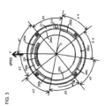
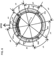
- FIG. 5 and FIG. 6 are diagrams schematically illustrating the mount of the interchangeable lens 3 seen from the camera body 2 side (seen from back of the interchangeable lens 3).
- a first lens-side line L1 extending in a vertical direction Y of the interchangeable lens 3, indicated with a solid line in FIG. 5 is in a vertical direction seen from a photographer who laterally holds the camera body 2 in the laterally holding using the camera system 1.
- a second lens-side line L2 extending in a horizontal direction X of the interchangeable lens 3, indicated with a solid line in FIG. 5 is in a horizontal direction seen from the photographer who laterally holds the camera body 2 in the laterally holding using the camera system 1.
- the first lens-side line L1 is orthogonal to the second lens-side line L2 on the optical axis O (center) of the interchangeable lens 3. As indicated with a dashed-dotted line in FIG. 5 , lines extending in directions intersecting with the first lens-side line L1 and the second lens-side line L2 on the optical axis O at 45 degrees are referred to as a third lens-side line L3 and a fourth lens-side line L4.
- the first body-side line B1 is aligned with the first lens-side line L1
- the second body-side line B2 is aligned with the second lens-side line L2
- the third body-side line B3 is aligned with the fourth lens-side line L4
- the fourth body-side line B4 is aligned with the third lens-side line L3.
- the lines do not have to completely are aligned with each other, and a gap may occur within a range in which the interchangeable lens 3 can be properly attached to the camera body 2 in a usable manner.
- the mount of the interchangeable lens 3 includes the lens-side mount 310 and the lens-side terminal holding unit 320 mentioned above in FIG. 1 .
- the lens-side mount 310 is formed in a circular shape centering around the optical axis O of the interchangeable lens 3, and is disposed along a surface orthogonal to the optical axis O.
- the lens-side mount 310 has a reference surface 311 which is to be in contact with the reference surface 211 of the body-side mount 210 once the interchangeable lens 3 is attached to the camera body 2.
- the reference surface 311 has a circular shape centering around the optical axis O, and is disposed along a surface orthogonal to the optical axis O.
- a slide surface for the lock pin 309 is formed in a concave shape recessed toward the -Z direction on a cross-section along the Z direction.
- a slide surface for the lock pin 309 allows the lock pin 214 which will be described later to slide in contacting state during the interchangeable lens 3 being attached.
- the slide surface for the lock pin 309 has a circular shape centering around the optical axis O, and is disposed along a surface orthogonal to the optical axis O.
- the lens-side mount 310 is fixed by being screwed at a fixing member disposed inside the interchangeable lens 3 using screws 313.
- the screws 313 are disposed around the optical axis O at intervals of approximately 90 degrees. Further, four screws 313 are respectively disposed on outer peripheries of four lens-side claw portions 390 which will be described later. Still further, the screws 313 are disposed on outer peripheries at both end portions of the lens-side terminal holding unit 320 in the circumferential direction.
- the lens-side mount 310 includes a cylindrical portion 312.
- the cylindrical portion 312 extendsin the direction along the optical axis O (herein after referred to as the optical axis O direction) at an inner peripheral edge portion of the lens-side mount 310, that is an inner peripheral edge portion of the reference surface 311.
- the lens-side mount 310 includes a first lens-side claw portion 390a, a second lens-side claw portion 390b, a third lens-side claw portion 390c and a fourth lens-side claw portion 390d. These four lens-side claw portions are arranged along an outer periphery of the rear end portion of the cylindrical portion 312 in the optical axis O direction at intervals.
- lens-side claw portion 390 these four first lens-side claw portion 390a to fourth lens-side claw portion 390d which are projecting portions will be collectively referred to as a lens-side claw portion 390.
- the lens-side claw portion 390 is provided at an outer peripheral edge portion of the cylindrical portion 312 of the lens-side mount 310 to project toward an outer periphery direction of the lens-side mount 310.
- the lens-side claw portion 390 is substantially orthogonal to the optical axis O. Further, the lens-side claw portion 390 extends in the circumferential direction around the optical axis O. As illustrated in FIG. 5 and FIG. 6 , the first lens-side claw portion 390a is disposed at an upper left position, the second lens-side claw portion 390b is disposed at an upper right position, the third lens-side claw portion 390c is disposed at a lower right position, and the fourth lens-side claw portion 390d is disposed at a lower left position.
- the first lens-side claw portion 390a is disposed in a region which is above the second lens-side line L2 and which is on the left side of the first lens-side line L1
- the second lens-side claw portion 390b is disposed in a region which is above the second lens-side line L2 and which is on the right side of the first lens-side line L1
- the third lens-side claw portion 390c is disposed in a region which is below the second lens-side line L2 and which is on the right side of the first lens-side line L1
- the fourth lens-side claw portion 390d is disposed in a region which is below the second lens-side line L2 and which is on the left side of the first lens-side line L1.
- first lens-side claw portion 390a and the third lens-side claw portion 390c are respectively disposed in regions which are on the third lens-side line L3 and which are substantially symmetric about the optical axis O
- second lens-side claw portion 390b and the fourth lens-side claw portion 390d are respectively disposed in regions which are on the fourth lens-side line L4 and which are substantially symmetric about the optical axis O.
- the third lens-side line L3 and the fourth lens-side line L4 do not necessarily pass through the central positions of the first lens-side claw portion 390a to the fourth lens-side claw portion 390d in relation to respective circumferential directions.
- the body-side claw portion 290 is disposed between the lens-side mount 310 and the lens-side claw portion 390 in the optical axis O direction.
- the first lens-side claw portion 390a comes into contact with the flat spring 213a of the first body-side claw portion 290a
- the second lens-side claw portion 390b comes into contact with the flat spring 213b of the second body-side claw portion 290b
- the third lens-side claw portion 390c comes into contact with the flat spring 213c of the third body-side claw portion 290c
- the fourth lens-side claw portion 390d comes into contact with the flat spring 213d of the fourth body-side claw portion 290d.
- the lens-side claw portion 390 includes a urged portion as a contact portion which is urged in a direction away from the body-side claw portion 290 by being brought into contact with the flat spring 213.
- the urged portion may have any shape if the lens-side claw portion 390 can receive sufficient urging force from the flat spring 213, and contact between the flat spring 213 and the urged portion may be one of point contact, line contact and surface contact.
- the flat spring 213 may have any shape and material if the flat spring 213 can sufficiently press the lens-side claw portion 390, and the shape and the material can be changed as appropriate.
- the lens-side claw portion 390 is pressed in a direction (+Z direction) away from the body-side claw portion 290 along the optical axis O by the flat spring 213 .
- the lens-side claw portion 390 being pressed in the +Z direction (toward the image sensor 270)
- the lens-side mount 310 is pressed toward the body-side mount 210, and attachment between the camera body 2 and the interchangeable lens 3 becomes stable.
- the lengths of the lens-side claw portion 390 and the body-side claw portion 290 in the circumferential direction do not have to be made the same, and the length of the lens-side claw portion 390 in the circumferential direction can be changed as long as the flat spring 213 can urge the lens-side claw portion 390.
- the whole surface of the lens-side claw portion 390 does not have to face the whole surface of the body-side claw portion 290 in a state where the interchangeable lens 3 is attached to the camera body 2, and a position of an end portion of the lens-side claw portion 390 in the circumferential direction may be different from a position of an end portion of the body-side claw portion 290 in the circumferential direction.
- lengths of the lens-side claw portion 390 and the body-side through portion 280 in the circumferential direction do not have to be made substantially the same, and the length of the lens-side claw portion 390 to be inserted, in the circumferential direction only has to be equal to or less than the length of the body-side through portion 280 in the circumferential direction.
- lengths of the body-side claw portion 290 and the lens-side through portion 380 in the circumferential direction do not have to be made the same, and the length of the body-side claw portion 290 to be inserted, in the circumferential direction only has to be equal to or less than the length of the lens-side through portion 380 in the circumferential direction.
- lengths of the first lens-side claw portion 390a to the fourth lens-side claw portion 390d in the circumferential direction are different from one another. Further, angles respectively formed by lines connecting one ends of the first lens-side claw portion 390a to the fourth lens-side claw portion 390d in the circumferential direction and the optical axis O and lines connecting the other ends of the first lens-side claw portion 390a to the fourth lens-side claw portion 390d in the circumferential direction and the optical axis O are different from one another.
- the third lens-side claw portion 390c is the longest
- the first lens-side claw portion 390a is the second longest
- the fourth lens-side claw portion 390d is the third longest
- the second lens-side claw portion 390b is the shortest.
- An angle ⁇ 7 formed by a line connecting one end of the third lens-side claw portion 390c and the optical axis O and a line connecting the other end of the third lens-side claw portion 390c and the optical axis O is approximately 48.5 degrees, and is between 48.0 degrees and 49.0 degrees.
- An angle ⁇ 5 formed by a line connecting one end of the first lens-side claw portion 390a and the optical axis O and a line connecting the other end of the first lens-side claw portion 390a and the optical axis O is approximately 48 degrees, and is between 47.5 degrees and 48.5 degrees.
- An angle ⁇ 8 formed by a line connecting one end of the fourth lens-side claw portion 390d and the optical axis O and a line connecting the other end of the fourth lens-side claw portion 390d and the optical axis O is approximately 44 degrees, and is between 43.0 degrees and 45.0 degrees.
- An angle ⁇ 6 formed by a line connecting one end of the second lens-side claw portion 390b and the optical axis O and a line connecting the other end of the second lens-side claw portion 390b and the optical axis O is approximately 36 degrees, and is between 35.5 degrees and 36.5 degrees.
- the angle ⁇ 6 formed by the line connecting the one end of the second lens-side claw portion 390b and the optical axis O and the line connecting the other end of the second lens-side claw portion 390b and the optical axis O is less than an angle of rotation required to rotate the interchangeable lens 3 for attaching to the camera body 2. The rotation angle will be described later.
- Lengths of the first lens-side claw portion 390a to the fourth lens-side claw portion 390d in a radial direction are substantially the same. Further, lengths of the first lens-side claw portion 390a to the fourth lens-side claw portion 390d in the optical axis O (thicknesses of the claw portions) direction are substantially the same.
- At least one of the lens-side claw portions 390 may be partially cut out as long as an attachment incompletion state between the camera body 2 and the interchangeable lens 3 is not affected.
- the whole including a projecting portion and a cut out portion disposed in a region facing the first body-side claw portion 290a is considered to be the first lens-side claw portion 390a. This will similarly apply to other second to fourth lens-side claw portions 390b to 390d.
- the first lens-side claw portion 390a may be cut out so as to be divided into two or more portions in the circumferential direction, or may be cut out so that part of the first lens-side claw portion 390a is cut out, or may be cut out so that a length of at least part of the first lens-side claw portion 390a in the radial direction becomes shorter. Therefore, part of the lens-side claw portion 390 on the third lens-side line L3 or the fourth lens-side line L4 may be cut out.
- a length of the first lens-side claw portion 390a in the circumferential direction may be changed as long as the first lens-side claw portion 390a passes through the corresponding first body-side through portion 280a upon insertion. This will similarly apply to the second lens-side claw portion 390b, the third lens-side claw portion 390c and the fourth lens-side claw portion 390d.
- a thickness of the cylindrical portion 312 in the radial direction can be changed as appropriate, and it is also possible to employ a shape in which at least part projects to an inner diameter side of the cylindrical portion 312 of the present embodiment.
- the lens-side claw portion 390 projects outward in the radial direction from an outer periphery of the cylindrical portion 312, and there is a portion where the lens-side claw portion 390 exists and a space portion where the lens-side claw portion 390 does not exist on the outer periphery of the cylindrical portion 312.
- space 380d between the first lens-side claw portion 390a and the fourth lens-side claw portion 390d on the outer periphery of the cylindrical portion 312 will be referred to as a first lens-side through portion 380a.
- space 380b between the first lens-side claw portion 390a and the second lens-side claw portion 390b will be referred to as a second lens-side through portion 380b
- space 380c between the second lens-side claw portion 390b and the third lens-side claw portion 390c will be referred to as a third lens-side through portion 380c
- space 380d between the third lens-side claw portion 390c and the fourth lens-side claw portion 390d will be referred to as a fourth lens-side through portion 380d.
- lens-side through portion 380 will be collectively referred to as a lens-side through portion 380.
- Lengths of the first lens-side through portion 380a to the fourth lens-side through portion 380d in the circumferential direction are different from one another. Specifically, the second lens-side through portion 380b is the longest, the first lens-side through portion 380a is the second longest, the fourth lens-side through portion 380d is the third longest, and the third lens-side through portion 380c is the shortest.
- An angle ⁇ 6 formed by a line connecting one end of the second lens-side through portion 380b and the optical axis O and a line connecting the other end of the second lens-side through portion 380b and the optical axis O is approximately 50 degrees, and is between 49.5 degrees and 50.5 degrees.
- An angle ⁇ 5 formed by a line connecting one end of the first lens-side through portion 380a and the optical axis O and a line connecting the other end of the first lens-side through portion 380a and the optical axis O is approximately 45 degrees, and is between 44.5 degrees and 45.5 degrees.
- An angle ⁇ 8 formed by a line connecting one end of the fourth lens-side through portion 380d and the optical axis O and a line connecting the other end of the fourth lens-side through portion 380d and the optical axis O is approximately 44.5 degrees, and is between 44.0 degrees and 45.0 degrees.
- An angle ⁇ 7 formed by a line connecting one end of the third lens-side through portion 380c and the optical axis O and a line connecting the other end of the third lens-side through portion 380c and the optical axis O is approximately 44 degrees, and is between 43.5 degrees and 44.5 degrees.
- a sum of the angles ⁇ 5 to ⁇ 8 of the four first lens-side claw portion 390a to the fourth lens-side claw portion 390d and the angles ⁇ 5 to ⁇ 8 of the four first lens-side through portion 380a to the fourth lens-side through portion 380d is 360 degrees.
- first lens-side through portion 380a and the third lens-side through portion 380c are respectively disposed in regions which are on the second lens-side line L2 and which are substantially symmetric about the optical axis O
- second lens-side through portion 380b and the fourth lens-side through portion 380d are respectively disposed in regions which are on the first lens-side line L1 and which are substantially symmetric about the optical axis O.
- first lens-side line L1 and the second lens-side line L2 do not have to pass through central positions in relation to the circumferential direction of the first lens-side through portion 380a to the fourth lens-side through portion 380d.
- the lens-side terminal holding unit 320 including a plurality of lens-side terminals is provided inside the cylindrical portion 312.
- the lens-side terminal holding unit 320 has an arc shape corresponding to a shape of the ring-shaped lens-side mount 310.
- the lens-side terminal holding unit 320 is preferably disposed at an upper part of the lens-side mount 310 along the opening of the lens-side mount 310 and disposed at the center of the upper part as illustrated in FIG. 5 and FIG. 6 . That is, the center of the lens-side terminal holding unit 320 in the circumferential direction is preferably located on the first lens-side line L1.
- the first lens-side claw portion 390a is disposed on an upper left side of the lens-side terminal holding unit 320
- the second lens-side through portion 380b is disposed on an upper right side of the lens-side terminal holding unit 320. Therefore, an angle formed by a line connecting one end of the lens-side terminal holding unit 320 and the optical axis O and a line connecting the other end of the lens-side terminal holding unit 320 and the optical axis O is smaller than a sum of the angle ⁇ 5 of the first lens-side claw portion 390a and the angle ⁇ 6 of the second lens-side through portion 380b.
- the lens-side terminal holding unit 320 has the plurality of lens-side terminals as described above.
- the plurality of lens-side terminals (which will be referred to as a lens-side terminal group) are disposed at the lens-side terminal holding unit 320 in a line inside the lens-side mount 310 in an arc shape.
- the lens-side terminal group are disposed so that respective conductive contact surfaces are exposed toward +Z direction ( FIG. 1 ).
- All the contact surfaces of the plurality of lens-side terminals may be located at a position in the +Z direction side from a rear end of the lens-side claw portion 390 in the optical axis O direction or may be located at a position in the -Z direction side from the rear end of the lens-side claw portion 390 in the optical axis O direction.
- part of the contact surfaces of the plurality of lens-side terminals may be located at a position in the +Z direction side from the rear end of the lens-side claw portion 390 in the optical axis O direction, and the remaining contact surfaces may be located at a position in the -Z direction side from the rear end of the lens-side claw portion 390 in the optical axis O direction.
- the lens-side mount 310 has a lock pin receiving portion 314.
- the lock pin receiving portion 314 is disposed on an upper left side of the fourth lens-side claw portion 390d as illustrated in FIG. 5 and FIG. 6 . That is, the lock pin receiving portion 314 is disposed between a portion corresponding to an outer periphery side of the first lens-side claw portion 390a and a portion corresponding to an outer periphery side of the fourth lens-side claw portion 390d among the slide surface for the lock pin 309 of the lens-side mount 310.
- the lock pin receiving portion 314 is a groove in which the lock pin 214 of the camera body 2 fits once the interchangeable lens 3 is attached to the camera body 2. This groove is provided in a concave shape recessed toward the -Z direction ( FIG. 1 ) from the slide surface for the lock pin 309 of the lens-side mount 310.
- an end portion of the lock pin 214 in the -Z direction (front end of the lock pin 214 on the subject side) fits in the lock pin receiving portion 314 of the lens-side mount 310. Further, in a state where the unlocking button of the camera body 2 is depressed, an end portion of the lock pin 214 in the -Z direction is located at a position in the +Z direction side from the slide surface for the lock pin 309. Therefore, rotating the interchangeable lens 3 and the camera body 2 relatively to each other while the unlocking button of the camera body 2 is depressed does not bring the lock pin 214 into contact with the slide surface for the lock pin 309.
- the plurality of body-side terminals respectively physically come into contact with the corresponding plurality of lens-side terminals.
- the plurality of body-side terminals are electrically connected to the plurality of lens-side terminals. That is, the plurality of body-side terminals are electrically conductive with the plurality of lens-side terminals.
- a restriction pin 315 is disposed between the reference surface 311 of the lens-side mount 310 and the fourth lens-side claw portion 390d and projects from an outer peripheral surface of the cylindrical portion 312.
- the restriction pin 315 is disposed on a rear end side or trailing side (position close to the third lens-side claw portion 390c) of the fourth lens-side claw portion 390d in the attaching direction 44.
- Part of the restriction pin 315 is disposed on a back side of the fourth lens-side claw portion 390d as the fourth lens-side claw portion 390d is seen from the back of the interchangeable lens 3.
- restriction pin 315 a screw member is used as the restriction pin 315, and the restriction pin 315 is screwed at the cylindrical portion 312 from outside in the radial direction, the shape and the material of the restriction pin 315 are not limited to this.
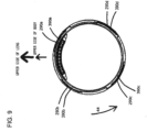
- FIG. 8 and FIG. 9 are diagrams illustrating positional relationship between the body-side claw portion 290 of the camera body 2 and the lens-side claw portion 390 of the interchangeable lens 3, and are diagrams for making a state where the claw portions abut on each other understandable. Further, FIG. 8 and FIG. 9 are diagrams of the body-side mount 210 and the lens-side mount 310, as seen from the subject side to the image sensor 270 side (seen in the +Z direction), and the lens-side mount 310 is horizontally inverted between FIG. 5 and FIG. 6 .
- the interchangeable lens 3 When the interchangeable lens 3 is attached to the camera body 2, first, a position of an index (not illustrated) provided on the outer peripheral surface of the interchangeable lens 3 and a position of an index (not illustrated) provided on an exterior surface of the camera body 2 are aligned, the body-side mount 210 and the lens-side mount 310 are made to face each other, and each lens-side claw portion 390 is inserted into each body-side through portion 280. That is, as illustrated in FIG.
- the first lens-side claw portion 390a is inserted into the first body-side through portion 280a
- the second lens-side claw portion 390b is inserted into the second body-side through portion 280b
- the third lens-side claw portion 390c is inserted into the third body-side through portion 280c
- the fourth lens-side claw portion 390d is inserted into the fourth body-side through portion 280d.
- the first body-side claw portion 290a is inserted into the second lens-side through portion 380b
- the second body-side claw portion 290b is inserted into the third lens-side through portion 380c
- the third body-side claw portion 290c is inserted into the fourth lens-side through portion 380d
- the fourth body-side claw portion 290d is inserted into the first lens-side through portion 380a.
- a position of the interchangeable lens 3 with respect to the camera body 2 at this time will be referred to as an insertion position and state where the interchangeable lens 3 at the insertion position can be inserted to the camera body 2 is insertion state.
- the interchangeable lens 3 is rotated in the attaching direction 44 illustrated in FIG. 8 from the above-described insertion position.
- the attaching direction 44 is a direction along the circumferential direction around the optical axis O in a plane which is substantially orthogonal to the optical axis O.
- the first body-side claw portion 290a and the flat spring 213a go into space between the first lens-side claw portion 390a and the reference surface 311.
- the interchangeable lens 3 is inserted in +Z direction, the first lens-side claw portion 390a goes into the image sensor 270 side (+Z side) of the first body-side claw portion 290a, and the first lens-side claw portion 390a faces the image sensor 270 side (+Z side) of the flat spring 213a.
- the first body-side claw portion 290a and the flat spring 213a go into space between the first lens-side claw portion 390a and the reference surface 311.
- the second body-side claw portion 290b and the flat spring 213b go into space between the second lens-side claw portion 390b and the reference surface 311
- the third body-side claw portion 290c and the flat spring 213c go into space between the third lens-side claw portion 390c and the reference surface 311
- the fourth body-side claw portion 290d and the flat spring 213d go into space between the fourth lens-side claw portion 390d and the reference surface 311.
- the lens-side terminals sequentially come into contact with the body-side terminals.
- interchangeable lens 3 is made to rotate in the attaching direction 44 with respect to the camera body 2, it is also possible to make the camera body 2 rotate in an opposite direction to the attaching direction 44 with respect to the interchangeable lens 3.
- FIG. 9 is a diagram of the interchangeable lens 3 which is rotated in the attaching direction 44 by a first angle (herein after referred to as first rotating angle) with respect to the camera body 2 from the insertion position in FIG. 8 , and illustrates a state where attachment of the interchangeable lens 3 to the camera body 2 is completed.
- the position of the interchangeable lens 3 at this time will be referred to as an attachment position.
- the first rotating angle is approximately 40 degrees in the present embodiment, and is between 38.5 degrees and 41.5 degrees.
- the lens-side claw portion 390 is pushed to the image sensor 270 side (+Z direction) by the flat spring 213and the reference surface 311 of the lens-side mount 310 comes into contact with the reference surface 211 of the body-side mount 210.
- the interchangeable lens 3 is tightly attached to the camera body 2.
- the plurality of lens-side terminals respectively come into contact with the corresponding plurality of body-side terminals, and are electrically connected to the plurality of body-side terminals.
- each lens-side claw portion 390 is inserted into each corresponding body-side through portion 280 at the insertion position in FIG. 8 until immediately before the attachment position in FIG. 9 will be referred to as an attachment incompletion state. Because the lock pin 214 of the camera body 2 is pushed in the -Z direction, in the attachment incompletion state, an end portion of the lock pin 214 in the -Z direction is in contact with the slide surface for the lock pin 309 of the lens-side mount 310.
- each lens-side claw portion 390 moves to a position of each body-side through portion 280 from a position facing an image side surface of each body-side claw portion 290, and reaches the insertion position illustrated in FIG. 8 .
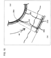
- FIG. 10 is a schematic diagram illustrating positional relationship between the fourth body-side claw portion 290d of the camera body 2 and the fourth lens-side claw portion 390d of the interchangeable lens 3.
- a part (a) on an upper side of a dashed-dotted line is a diagram seen from the subject side to the image sensor 270 side, and a part (b) on a lower side of the dashed-dotted line is a diagram of a lens mount mechanism seen from a side.
- FIG. 11 is a diagram of part of the lens mount mechanism in the over-rotated state in the removing direction, as seen from a side.
- the restriction pin 315 is disposed at a trailing end portion of the fourth lens-side claw portion 390d in the attaching direction 44, if the user tries to inversely rotate the interchangeable lens 3 after the interchangeable lens 3 is inserted into the camera body 2, the restriction pin 315 abuts on a tip of the third body-side claw portion 290c in the attaching direction 44, so that further rotation of the interchangeable lens 3 in the removing direction with respect to the camera body 2 is prevented.
- restriction pin 315 prevents over rotation by utilizing the end portion of the body-side claw portion 290 in the circumferential direction, it is not necessary to separately provide a member which abuts on the restriction pin 315 upon over rotation.
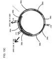
- FIG. 13A , 13B and 13C are schematic diagrams illustrating positional relationship between the body-side claw portion 290 of the camera body 2 and the lens-side claw portion 390 of the interchangeable lens 3, and are diagrams for making a state where the claw portions abut on each other understandable.
- FIG. 12 and FIG. 13A , 13B and 13C are diagrams of the body-side mount 210 and the lens-side mount 310, as seen from the subject side to the image sensor 270 side (seen in the +Z direction), and the lens-side mount 310 is horizontally inverted between FIG. 5 and FIG. 6 .
- FIG. 12 a state where the index of the interchangeable lens 3 and the index of the camera body 2 are displaced from the insertion position in the removing direction by 15 degrees is illustrated in FIG. 12 . Further, states where the index of the interchangeable lens 3 and the index of the camera body 2 are displaced from the insertion position at intervals of 90 are illustrated in FIG. 13A to FIG. 13C .
- FIG. 12 illustrates a state where the indexes are displaced from the insertion position in the removing direction by 15 degrees (first erroneous insertion state).
- first erroneous insertion state a state where the indexes are displaced from the insertion position in the removing direction by 15 degrees.
- the lens-side claw portion 390 abuts on the body-side claw portion 290 at portions indicated with four reference signs ⁇ 1 to ⁇ 4
- the lens-side claw portion 390 is not inserted into the body-side through portion 280. That is, in the first erroneous insertion state, by the lens-side claw portion 390 abutting on the body-side claw portion 290 at four portions, erroneous insertion is reliably prevented.
- FIG. 13A is a diagram illustrating a state where the index of the interchangeable lens 3 and the index of the camera body 2 are displaced from the insertion position in the removing direction by approximately 90 degrees (second erroneous insertion state).
- FIG. 13B is a diagram illustrating a third erroneous insertion state where the index of the interchangeable lens 3 and the index of the camera body 2 are displaced from the insertion position in the removing direction by approximately 180 degrees.
- FIG. 13C is a diagram illustrating a fourth erroneous insertion state where the index of the interchangeable lens 3 and the index of the camera body 2 are displaced from the insertion position in the removing direction by approximately 270 degrees.
- the interchangeable lens 3 it is possible to properly attach the interchangeable lens 3 to the camera body 2 in a usable manner.
- the four lens-side claw portions 390 are respectively pressed in the +Z direction from the flat springs 213 of the four body-side claw portions 290 once the interchangeable lens 3 is attached to the camera body 2, even in the case where one of the interchangeable lens 3 and the camera body 2 is subjected to impact, because there are respectively four projecting portions (the lens-side claw portion 390, the body-side claw portion 290), high impact resistance is provided.
- the interchangeable lens 3 is attached to the camera body 2, it is possible to perform communication, power supply and control between the camera body 2 and the interchangeable lens 3 through respective terminals of the camera body 2 and the interchangeable lens 3, so that it is possible to properly use the camera system 1.
- the four projecting portions of the interchangeable lens 3 are disposed on two lines intersecting with a line connecting the center of a contact point holding unit and the optical axis O at approximately 45 degrees on the optical axis O, come into contact with the four flat springs 213 disposed around the optical axis O at intervals of approximately 90 degrees and face the four projecting portions of the camera body 2.
- high impact resistance is provided both in the case where the camera system 1 is laterally or horizontally held and longitudinally held.
- the second body-side claw portion 290b and the fourth body-side claw portion 290d are disposed on the third body-side line B3, and the first body-side claw portion 290a and the third body-side claw portion 290c are disposed on the fourth body-side line B4.
- the angle ⁇ 4 of the fourth body-side claw portion 290d is the third largest among the four body-side claw portions 290
- the angle ⁇ 2 of the second body-side claw portion 290b is the smallest (fourth largest) among the four body-side claw portions 290.
- the angle ⁇ 1 of the first body-side claw portion 290a is the largest among the four body-side claw portions 290
- the angle ⁇ 3 of the third body-side claw portion 290c is the second largest among the four body-side claw portions.
- the first lens-side claw portion 390a and the third lens-side claw portion 390c are disposed on the third lens-side line L3, and the second lens-side claw portion 390b and the fourth lens-side claw portion 390d are disposed on the fourth lens-side line L4.
- the angle ⁇ 8 of the fourth lens-side claw portion 390d is the third largest among the four lens-side claw portion 390
- the angle ⁇ 6 of the second lens-side claw portion 390b is the smallest (the fourth largest) among the four lens-side claw portions 390.
- the angle ⁇ 5 of the first lens-side claw portion 390a is the second largest among the four lens-side claw portions
- the angle ⁇ 7 of the third lens-side claw portion 390c is the largest among the four lens-side claw portions.
- the angle of the third lens-side claw portion 390c is larger among the first lens-side claw portion 390a and the third lens-side claw portion 390c disposed on the third lens-side line L3
- the angle of the fourth lens-side claw portion 390d is larger among the second lens-side claw portion 390b and the fourth lens-side claw portion 390d disposed on the fourth lens-side line L4. That is, the two lens-side claw portions 390 on the lower side of the second lens-side line L2 (extending in a horizontal direction) are larger among the two lens-side claw portions 390 facing across the optical axis O.
- the interchangeable lens 3 it is possible to receive impact received on the interchangeable lens 3 from a lower direction with a large area of the two lens-side claw portions 390 with the large angle on the lower side of the second lens-side line L2 in a state where the camera system is horizontally held. Further, in the case where the interchangeable lens 3 is subjected to impact from a lower direction in a state where the camera system is horizontally held, the lens-side claw portions 390 on the lower side of the second lens-side line L2 are subjected to impact in a direction (-Z direction) closer to the body-side claw portion 290.
- the flat spring 213 presses the lens-side claw portion 390 in a direction (+Z direction) away from the body-side claw portion 290.
- the interchangeable lens 3 is subjected to impact from a lower direction in a state where the camera system is horizontally held, because the lens-side claw portions 390 on the lower side of the second lens-side line L2 can absorb impact with a large area and also with urging force of the flat springs 213 of the body-side claw portions 290 which face each other, high impact resistance is provided.
- the lens-side terminal holding unit 320 is disposed above the image sensor 270 in a state where the interchangeable lens 3 is attached to the camera body 2. Because sunlight incident on the interchangeable lens 3 is incident on a lower side on an exit side of the interchangeable lens 3 in a state where the camera system 1 is horizontally held. In this situation, while ghost is likely to occur on the lower side of the image sensor 270, because, in the present embodiment, the lens-side terminal holding unit 320 is disposed not below but above the image sensor 270, it is possible to suppress ghost.
- the four flat springs 213 are disposed around the optical axis O at intervals of approximately 90 degrees. Therefore, at least two flat springs 213 among the four flat springs 213 come into contact with the two lens-side claw portions 390 across the optical axis O, and the two lens-side claw portions 390 are pressed in the +Z direction.
- the interchangeable lens 3 includes four lens-side claw portions 390, even in the case where one lens-side claw portion 390 among the four lens-side claw portions 390 of the interchangeable lens 3 is broken, because at least two lens-side claw portions 390 are disposed at positions facing each other across the optical axis O, the lens-side claw portion 390 is pressed with the two flat springs 213 disposed at positions facing each other across the optical axis O. Therefore, it is possible to provide the camera system 1 in which the interchangeable lens 3 can be attached to the camera body 2 in a usable manner even if the lens-side claw portions 390 of the interchangeable lens 3 are broken and the number of lens-side claw portions 390 becomes insufficient.
- the flat spring 213 is located on the line B5 ( FIG. 4 ), it is possible to strongly press the lens-side terminals near the line B5 to the body-side terminals.
- one of the two lens-side claw portions is disposed at a position close to the center of the lens-side terminal holding unit 320.
- the lens-side claw portion being disposed at a position close to the center of the lens-side terminal holding unit 320 and brought into contact with the flat spring 213, it is possible to properly use the camera system 1 while bringing the lens-side terminals contact with the body-side terminals.
- a material of the lens-side mount 310 is not particularly limited, and may be a metal or a resin. Further, an end portion of the lens-side mount 310 (such as an end portion of an outer periphery side of the lens-side claw portion 390, an end portion of the lens-side claw portion 390 in a circumferential direction, and an end portion of the cylindrical portion 312 in the optical axis O direction) may be formed such that at least part is sloped. An end portion of the lens-side mount 310 does not have to be sloped and may be partially stepped.
- a shape of the lens-side terminal holding unit 320 is not particularly limited, and can be changed as appropriate. Particularly, by causing the end portion of the lens-side terminal holding unit 320 in the circumferential direction to be sloped, it is possible to smoothly bring the lens-side terminal holding unit 320 into contact with the body-side terminal holding unit 220 while the interchangeable lens 3 is rotated from the insertion position to the attachment position.
- the lens-side terminal holding unit 320 includes a plurality of lens-side terminals disposed in an arc shape, the positions of the lens-side terminals may be displaced as long as the lens-side terminals come into contact with the body-side terminals once the interchangeable lens 3 is attached to the camera body 2.
- a central position and a length of the lens-side claw portion 390 in the circumferential direction can be changed as appropriate within a range where the lens-side claw portion 390 can be pressed from the flat spring 213 at the attachment position.
- the central position of the lens-side claw portion 390 in the circumferential direction and the central position of the urged portion in the circumferential direction may be located at different positions. That is, a position where the lens-side claw portion 390 is pressed from the central position of the flat spring 213 in the circumferential direction may be different from the central position of the lens-side claw portion 390 in the circumferential direction.
- the central position of the lens-side claw portion 390 in the circumferential direction does not have to coincide with the central position of the body-side claw portion 290 in the circumferential direction at the attachment position.
- the length of the lens-side claw portion 390 in the circumferential direction does not have to be the same as the length of the corresponding body-side claw portion 290 in the circumferential direction.
- the interchangeable lens 3 of the camera system 1 has been described as an example of the accessory, the accessory is not limited to the interchangeable lens 3.
- a tele converter, a wide converter, a close-up ring, or the like which is attached between the camera body 2 and the interchangeable lens 3, and which changes a focal length of the interchangeable lens 3 may be used.
- the present invention it is also possible to apply the present invention to a mount adapter, or the like, which enables an accessory including the interchangeable lens 3 conforming to mount standards other than the mount standards of the camera body 2 to be able to be attached to the above-mentioned camera body 2. That is, the present invention can be similarly applied to any accessory which is used by being attached to the mount of the camera body 2.
- the lens-side claw portion, the lens-side terminal, or the like respectively correspond to an accessory side projecting portion, an accessory side terminal, or the like, of the accessory.
- the accessory which can be removably attached to the camera body 2 may be a mount adapter which enables the interchangeable lens 3 conforming to the above-mentioned mount standards to be attached to a camera body which conforms to mount standards different from the above-mentioned mount standards, and it is also possible to employ a configuration where the above-mentioned accessory can be attached to the mount adapter.
Landscapes
- Physics & Mathematics (AREA)
- General Physics & Mathematics (AREA)
- Optics & Photonics (AREA)
- Structure And Mechanism Of Cameras (AREA)
Claims (15)
- Zubehör (1), das abnehmbar an einem Kamerakörper (2) befestigt werden kann, wobei der Kamerakörper aufweist:einen Bildsensor (270), der eine rechteckige Form mit einer oberen Seite, einer unteren Seite, einer rechten Seite und einer linken Seite in einem Fall aufweist, in dem der Kamerakörper horizontal gehalten wird, wobei der Bildsensor einfallendes Subjektlicht empfängt, das sich um eine optische Achse (O) herum zentriert;ein körperseitige Anschlussgruppe mit einer Mehrzahl von körperseitigen Anschlüssen, die oberhalb der oberen Seite des Bildsensors angeordnet ist;eine ringförmige körperseitige Halterung (210), die außerhalb des Bildsensors und der körperseitigen Anschlussgruppe angeordnet ist, und eine Ringform ist ausgebildet, die sich um die optische Achse herum zentriert,einen ersten körperseitigen vorstehenden Abschnitt (290a), der von der körperseitigen Halterung in einer Innendurchmesserrichtung vorsteht;ein erstes elastisches Element (213a), das an einer Bildseite des ersten körperseitigen vorstehenden Abschnitt angeordnet ist;einen zweiten körperseitigen vorstehenden Abschnitt (290b), der von der körperseitigen Halterung in einer Innendurchmesserrichtung vorsteht;ein zweites elastisches Element (213b), das an einer Bildseite des ersten körperseitigen vorstehenden Abschnitt angeordnet ist;einen dritten körperseitigen vorstehenden Abschnitt (290c), der von der körperseitigen Halterung in einer Innendurchmesserrichtung vorsteht;ein drittes elastisches Element (213c), das an einer Bildseite des ersten körperseitigen vorstehenden Abschnitt angeordnet ist;einen vierten körperseitigen vorstehenden Abschnitt (290d), der von der körperseitigen Halterung in einer Innendurchmesserrichtung vorsteht; andein viertes elastisches Element (213d), das an einer Bildseite des ersten körperseitigen vorstehenden Abschnitt angeordnet ist;wobei das erste elastische Element, das zweite elastische Element, das dritte elastische Element und das vierte elastische Element jeweils in vier Bereichen angeordnet sind, die durch eine erste körperseitige Linie, die durch eine Mitte in Umfangsrichtung der körperseitigen Anschlussgruppe und die optische Achse verläuft, und eine zweite körperseitige Linie, die orthogonal zu der ersten körperseitigen Linie an der optischen Achse ist, unterteilt sind, wobei das Zubehör aufweist:eine zubehörseitige Halterung (310) von einer Ringform, die sich um eine optische Achse herum zentriert, wobei die zubehörseitige Halterung ausgestaltet ist, mit der körperseitigen Halterung in Kontakt zu sein;einen zylindrischen Abschnitt (312), der sich in der optischen Richtung von einem inneren Umfangskantenabschnitt der zubehörseitigen Halterung erstreckt;eine zubehörseitige Anschlussgruppe, die innerhalb des zylindrischen Abschnitts angeordnet ist, wobei die zubehörseitige Anschlussgruppe eine Mehrzahl von zubehörseitigen Anschlüssen aufweist, die dazu ausgestaltet ist, mit den körperseitigen Anschlüssen bei Befestigung an dem Kamerakörper in Kontakt zu sein;eine Mehrzahl von zubehörseitigen vorstehenden Abschnitten, die einen ersten zubehörseitigen vorstehenden Abschnitt (390a), der von dem zylindrischen Abschnitt in einer äußeren Umfangsrichtung der zubehörseitigen Halterung vorsteht und sich in einer Umfangsrichtung um die optische Achse herum erstreckt undeinen dritten zubehörseitigen vorstehenden Abschnitt (390c), der von dem zylindrischen Abschnitt in einer äußeren Umfangsrichtung der zubehörseitigen Halterung vorsteht und sich in einer Umfangsrichtung um die optische Achse herum erstreckt, umfasst; dadurch gekennzeichnet, dass:der erste zubehörseitige vorstehende Abschnitt und der dritte zubehörseitige vorstehende Abschnitt dazu ausgestaltet sind, mit zwei elastischen Elementen von dem ersten elastischen Element, dem zweiten elastischen Element, dem dritten elastischen Element und dem vierten elastischen Element, die einander über die optische Achse gegenüber sind, bei Befestigung an dem Kamerakörper in Kontakt zu sein;der erste zubehörseitige vorstehende Abschnitt in einer äußeren Umfangsrichtung der und an einer Seite in der Umfangsrichtung der zubehörseitigen Anschlussgruppe angeordnet ist; undein zweiter zubehörseitiger Durchgangsabschnitt (380b) in der äußeren Umfangsrichtung und an einer anderen Seite in der Umfangsrichtung der zubehörseitigen Anschlussgruppe angeordnet ist, durch den der erste körperseitige vorstehende Abschnitt, der der nächste zur Mitte der körperseitigen Anschlussgruppe ist unter den körperseitigen vorstehenden Abschnitten ist, an einer Einsetzposition eingesetzt ist, an der die Mehrzahl von zubehörseitigen vorstehenden Abschnitten zwischen den jeweils entsprechenden ersten, zweiten, dritten und vierten körperseitigen vorstehenden Abschnitten eingesetzt sind.
- Zubehör nach Anspruch 1, wobei:
ein Winkel, der durch eine Linie, die ein Ende der zubehörseitigen Anschlussgruppe in der Umfangsrichtung und die optische Achse verbindet, und eine Linie, die ein anderes Ende der zubehörseitigen Anschlussgruppe in der Umfangsrichtung und die optische Achse verbindet, ausgebildet ist, kleiner ist als eine Summe von eines Winkels, der der durch eine Linie, die ein Ende des ersten zubehörseitigen vorstehenden Abschnitts in der Umfangsrichtung und die optische Achse verbindet, und eine Linie, die ein anderes Ende des ersten zubehörseitigen vorstehenden Abschnitts in der Umfangsrichtung und die optische Achse verbindet, ausgebildet ist, und eines Winkels, der durch eine Linie, die ein Ende des zweiten zubehörseitigen Durchgangsabschnitts in der Umfangsrichtung und die optische Achse verbindet, und eine Linie, die ein anderes Ende des zweiten zubehörseitigen Durchgangsabschnitts in der Umfangsrichtung und die optische Achse verbindet, ausgebildet ist. - Zubehör nach Anspruch 1 oder 2, wobei:
sich ein erster Mittelwinkel, der durch eine Linie, die ein Ende des ersten zubehörseitigen vorstehenden Abschnitts in der Umfangsrichtung und die optische Achse verbindet, und eine Linie, die das andere Ende des ersten zubehörseitigen vorstehenden Abschnitts in der Umfangsrichtung und die optische Achse verbindet, ausgebildet ist, von einem dritten Mittelwinkel, der durch eine Linie, die ein Ende des dritten zubehörseitigen vorstehenden Abschnitts in der Umfangsrichtung und die optische Achse verbindet, und eine Linie, die das andere Ende des dritten zubehörseitigen vorstehenden Abschnitts in der Umfangsrichtung und die optische Achse verbindet, ausgebildet ist, unterscheidet. - Zubehör nach einem der Ansprüche 1 bis 3, wobei:
jeder der Mehrzahl von zubehörseitigen vorstehenden Abschnitten jeweils in jedem von vier Bereichen angeordnet sind, die durch eine erste zubehörseitige Linie, die durch eine Mitte der zubehörseitigen Anschlussgruppe und die optische Achse verläuft, und eine zweite zubehörseitige Linie, die orthogonal zu der ersten zubehörseitigen Linie an der optischen Achse ist, unterteilt ist. - Zubehör nach einem der Ansprüche 1 bis 4, wobei:der erste zubehörseitige vorstehende Abschnitt einen ersten Kontaktabschnitt aufweist, der mit dem ersten elastischen Element in Kontakt ist;sich der erste Kontaktabschnitt in der Umfangsrichtung um die optische Achse herum erstreckt; undsich eine Mittelposition des ersten Kontaktabschnitts in der Umfangsrichtung an einer Position befindet, die sich von einer Mittelposition des ersten zubehörseitigen vorstehenden Abschnitts in der Umfangsrichtung unterscheidet.
- Zubehör nach einem der Ansprüche 1 bis 5, wobei:der erste zubehörseitige vorstehende Abschnitt einen ersten Kontaktabschnitt aufweist, der dazu ausgestaltet ist, mit dem ersten elastischen Element in Kontakt zu sein; undzumindest ein Teil der zubehörseitigen Anschlussgruppe an einer inneren Seite des ersten Kontaktabschnitts angeordnet ist.
- Zubehör nach einem der Ansprüche 1 bis 6, wobei:der erste zubehörseitige vorstehende Abschnitt einen ersten Kontaktabschnitt aufweist, der dazu ausgestaltet ist, mit dem ersten elastischen Element in Kontakt zu sein;der dritte zubehörseitige vorstehende Abschnitt einen dritten Kontaktabschnitt aufweist, der dazu ausgestaltet ist, mit dem dritten elastischen Element in Kontakt zu sein;ein Ende des zubehörseitigen Anschlusses an einer inneren Seite des ersten Kontaktabschnitts angeordnet ist; undder erste Kontakt über die optische Achse gegenüber des dritten Kontaktabschnitts angeordnet ist.
- Zubehör nach einem der Ansprüche 1 bis 7, wobei die Mehrzahl der zubehörseitigen vorstehenden Abschnitte ferner aufweist:einen zweiten zubehörseitigen vorstehenden Abschnitt (390b), der von dem zylindrischen Abschnitt in der äußeren Umfangsrichtung der zubehörseitigen Halterung vorsteht und sich in der Umfangsrichtungsrichtung um die optische Achse herum erstreckt;einen vierten zubehörseitigen vorstehenden Abschnitt (390d), der von dem zylindrischen Abschnitt in der äußeren Umfangsrichtung der zubehörseitigen Halterung vorsteht und sich in der Umfangsrichtungsrichtung um die optische Achse herum erstreckt, wobei:der erste zubehörseitige vorstehende Abschnitt dazu ausgestaltet ist, in Kontakt mit dem ersten elastischen Element zu sein;der zweite zubehörseitige vorstehende Abschnitt dazu ausgestaltet ist, in Kontakt mit dem zweiten elastischen Element zu sein;der dritte zubehörseitige vorstehende Abschnitt dazu ausgestaltet ist, in Kontakt mit dem dritten elastischen Element zu sein; undder vierte zubehörseitige vorstehende Abschnitt dazu ausgestaltet ist, in Kontakt mit dem vierten elastischen Element zu sein.
- Zubehör nach Anspruch 8, wobei:
der erste zubehörseitige vorstehende Abschnitt und der dritte zubehörseitige vorstehende Abschnitt sind an einer dritten zubehörseitigen Linie angeordnet, die eine erste zubehörseitige Linie, die durch eine Mitte der zubehörseitigen Anschlussgruppe verläuft, und die optische Achse schneidet, die optische Achse in einem Winkel von etwa 45 Grad, und der zweite zubehörseitige vorstehende Abschnitt und der vierte zubehörseitige vorstehende Abschnitt an einer vierten zubehörseitigen Linie angeordnet sind, die orthogonal zu der dritten zubehörseitigen Linie an der optischen Achse ist. - Zubehör nach Anspruch 8 oder 9, wobei:der erste zubehörseitige vorstehende Abschnitt einen ersten Kontaktabschnitt aufweist, der dazu ausgestaltet ist, mit dem ersten elastischen Element in Kontakt zu sein;der zweite zubehörseitige vorstehende Abschnitt einen zweiten Kontaktabschnitt aufweist, der dazu ausgestaltet ist, mit dem zweiten elastischen Element in Kontakt zu sein;der dritte zubehörseitige vorstehende Abschnitt einen dritten Kontaktabschnitt aufweist, der dazu ausgestaltet ist, mit dem dritten elastischen Element in Kontakt zu sein;der vierte zubehörseitige vorstehende Abschnitt einen vierte Kontaktabschnitt aufweist, der dazu ausgestaltet ist, mit dem vierten elastischen Element in Kontakt zu sein; undder erste Kontaktabschnitt, der zweite Kontaktabschnitt, der dritte Kontaktabschnitt und der vierte Kontaktabschnitt um die optische Achse herum in Intervallen von 90 Grad angeordnet sind.
- Zubehör nach einem der Ansprüche 8 bis 10, wobei:ein dritter Mittelwinkel, der durch eine Linie, die ein Ende des dritten zubehörseitigen vorstehenden Abschnitts in der Umfangsrichtung und die optische Achse verbindet, und eine Linie, die das andere Ende des dritten zubehörseitigen vorstehenden Abschnitts in der Umfangsrichtung und die optische Achse verbindet, ausgebildet ist, größer ist als ein erster Mittelwinkel, der durch eine Linie, die das eine Ende des ersten zubehörseitigen vorstehenden Abschnitts in der Umfangsrichtung und die optische Achse verbindet, und eine Linie, die das andere Ende des ersten zubehörseitigen vorstehenden Abschnitts in der Umfangsrichtung und die optische Achse verbindet, ausgebildet ist;der erste Mittelwinkel größer ist als ein vierter Mittelwinkel, der durch eine Linie, die ein Ende des vierten zubehörseitigen vorstehenden Abschnitts in der Umfangsrichtung und die optische Achse verbindet, und eine Linie, die das andere Ende des vierten zubehörseitigen vorstehenden Abschnitts in der Umfangsrichtung und die optische Achse verbindet, ausgebildet ist; undder vierte Mittelwinkel größer ist als ein zweiter Mittelwinkel, der durch eine Linie, die ein Ende des zweiten zubehörseitigen vorstehenden Abschnitts in der Umfangsrichtung und die optische Achse verbindet, und eine Linie, die das andere Ende des zweiten zubehörseitigen vorstehenden Abschnitts in der Umfangsrichtung und die optische Achse verbindet, ausgebildet ist; wobei fernerder erste zubehörseitige vorstehende Abschnitt und der dritte zubehörseitige vorstehende Abschnitt an einer dritten zubehörseitigen Linie angeordnet sind, die eine erste zubehörseitige Linie, die durch eine Mitte der zubehörseitigen Anschlussgruppe verläuft, und die optische Achse schneidet, die optische Achse in einem Winkel von etwa 45 Grad; undder zweite zubehörseitige vorstehende Abschnitt und der vierte zubehörseitige vorstehende Abschnitt an einer vierten zubehörseitigen Linie angeordnet sind, die orthogonal zu der dritten zubehörseitigen Linie an der optischen Achse angeordnet ist;
- Zubehör nach einem der Ansprüche 8 bis 11, wobei:
das Zubehör an dem Kamerakörper durch gedreht Werden um einen ersten Winkel in einer ersten Richtung in einer Ebene, die im Wesentlichen orthogonal zu der optischen Achse an einer vorbestimmten Position an der optischen Achse von der Einsetzposition, an der der erste zubehörseitige vorstehende Abschnitt bis der vierte zubehörseitige vorstehende Abschnitt zwischen den jeweils entsprechenden ersten bis vierten körperseitigen vorstehenden Abschnitten, die von der körperseitigen Halterung in einer Innendurchmesserrichtung vorstehen, eingesetzt sind, an einer Befestigungsposition befestigbar ist, an der der erste zubehörseitige vorstehende Abschnitt bis der vierte zubehörseitige vorstehende Abschnitt den jeweils entsprechenden körperseitigen vorstehenden Abschnitten zugewandt sind. - Zubehör nach Anspruch 12, wobei:
an einer fehlerhaften Einsetzposition, die eine Position ist, die sich von der Einsetzposition in Umfangsrichtung um die optische Achse herum unterscheidet, zumindest zwei von dem ersten zubehörseitigen vorstehenden Abschnitt, dem zweiten zubehörseitigen vorstehenden Abschnitt, dem dritten zubehörseitigen vorstehenden Abschnitt und dem vierten zubehörseitigen vorstehenden Abschnitt an zumindest zwei von dem ersten körperseitigen vorstehenden Abschnitt, dem zweiten körperseitigen vorstehenden Abschnitt, dem dritten körperseitigen vorstehenden Abschnitt und dem vierten körperseitigen vorstehenden Abschnitt anliegen. - Zubehör nach Anspruch 12 oder 13, wobei:
ein Mittelwinkel von zumindest einem von dem ersten zubehörseitigen vorstehenden Abschnitt, dem zweiten zubehörseitigen vorstehenden Abschnitt, dem dritten zubehörseitigen vorstehenden Abschnitt und dem vierten zubehörseitigen vorstehenden Abschnitt, der durch eine Line, die ein Ende des entsprechenden zubehörseitigen vorstehenden Abschnitts in der Umfangsrichtung und die optische Achse verbindet, und eine Line, die das andere Ende des entsprechenden zubehörseitigen vorstehenden Abschnitts in der Umfangsrichtung und die optische Achse verbindet, ausgebildet ist, kleiner ist als der erste Winkel. - Zubehör nach einem der Ansprüche 1 bis 14, wobei:
das Zubehör eine austauschbare Linse ist.
Applications Claiming Priority (1)
| Application Number | Priority Date | Filing Date | Title |
|---|---|---|---|
| JP2017206882A JP6521023B2 (ja) | 2017-10-26 | 2017-10-26 | アクセサリ |
Publications (2)
| Publication Number | Publication Date |
|---|---|
| EP3477377A1 EP3477377A1 (de) | 2019-05-01 |
| EP3477377B1 true EP3477377B1 (de) | 2025-01-08 |
Family
ID=63998592
Family Applications (1)
| Application Number | Title | Priority Date | Filing Date |
|---|---|---|---|
| EP18202576.7A Active EP3477377B1 (de) | 2017-10-26 | 2018-10-25 | Bajonettverbindung für objektive |
Country Status (4)
| Country | Link |
|---|---|
| US (1) | US11054604B2 (de) |
| EP (1) | EP3477377B1 (de) |
| JP (1) | JP6521023B2 (de) |
| CN (5) | CN119620517A (de) |
Families Citing this family (3)
| Publication number | Priority date | Publication date | Assignee | Title |
|---|---|---|---|---|
| CN110226126B (zh) * | 2017-01-27 | 2021-06-11 | 富士胶片株式会社 | 相机系统、可换镜头、相机及相机系统的电源供给方法 |
| JP6569715B2 (ja) * | 2017-10-26 | 2019-09-04 | 株式会社ニコン | アクセサリ |
| JP2020144255A (ja) * | 2019-03-07 | 2020-09-10 | キヤノン株式会社 | カメラマウント、撮像装置、および、カメラマウントの製造方法 |
Family Cites Families (31)
| Publication number | Priority date | Publication date | Assignee | Title |
|---|---|---|---|---|
| JPS6039212B2 (ja) | 1975-06-23 | 1985-09-05 | ブロニカ株式会社 | レンズシヤツタ−式カメラにおけるレンズ取付装置 |
| US4307954A (en) * | 1980-08-18 | 1981-12-29 | Ludwig Robert B | Bayonet mount |
| JPS6331048Y2 (de) * | 1986-02-17 | 1988-08-19 | ||
| JPS62195633A (ja) * | 1986-02-24 | 1987-08-28 | Canon Inc | 光学付属品 |
| SE458893B (sv) * | 1987-09-15 | 1989-05-16 | Hasselblad Ab Victor | Elektriskt kontaktblock |
| JPH01169882U (de) * | 1988-05-23 | 1989-11-30 | ||
| JP3251131B2 (ja) * | 1994-07-29 | 2002-01-28 | 京セラ株式会社 | カメラのマウント構造 |
| JP3864500B2 (ja) * | 1997-06-27 | 2006-12-27 | 株式会社ニコン | カメラシステム、及び、カメラの像ブレ補正方法 |
| JP3511229B2 (ja) | 1998-07-31 | 2004-03-29 | 京セラ株式会社 | カメラ付属品の取付検出装置 |
| JP2000089332A (ja) | 1998-09-08 | 2000-03-31 | Iiyama Cosina Co Ltd | カメラのレンズ組立体の取付構造 |
| JP2004102005A (ja) * | 2002-09-11 | 2004-04-02 | Fuji Photo Film Co Ltd | カメラのバヨネット式レンズマウント |
| KR20050067088A (ko) * | 2003-12-26 | 2005-06-30 | 교세라 가부시키가이샤 | 카메라 모듈 및 이 카메라 모듈을 구비한 휴대 단말기 |
| JP2006267367A (ja) * | 2005-03-23 | 2006-10-05 | Konica Minolta Photo Imaging Inc | 撮像システム、撮像装置用の充電装置および撮像装置 |
| EP1808729B1 (de) * | 2006-01-17 | 2009-04-22 | Leica Camera AG | Wechselobjektiv mit optisch lesbarer Kennung |
| DE102006019449A1 (de) | 2006-04-24 | 2007-10-25 | Leica Camera Ag | Verfahren und Vorrichtung zur Identifizierung von Wechselobjektiven |
| JP2008256937A (ja) * | 2007-04-04 | 2008-10-23 | Topcon Corp | 光学装置の組立方法、光学装置、連結部材用工具、その工具による連結部材取付方法及び連結部材取外し方法 |
| US20110176035A1 (en) * | 2008-06-27 | 2011-07-21 | Anders Poulsen | Tilt and shift adaptor, camera and image correction method |
| JP5228691B2 (ja) | 2008-08-12 | 2013-07-03 | 株式会社ニコン | 光学機器のマウント構造及び光学機器 |
| US7941045B2 (en) * | 2008-10-30 | 2011-05-10 | Panasonic Corporation | Camera body, interchangeable lens unit, and imaging apparatus |
| JP5041081B2 (ja) | 2010-09-06 | 2012-10-03 | 株式会社ニコン | カメラ用アクセサリ、アクセサリ側マウント、カメラボディおよびボディ側マウント |
| JP5541142B2 (ja) | 2010-12-20 | 2014-07-09 | 株式会社ニコン | カメラ用アクセサリ、アクセサリ側マウント、カメラボディおよびボディ側マウント |
| JP5445479B2 (ja) | 2011-01-28 | 2014-03-19 | 株式会社ニコン | カメラ用アクセサリ、アクセサリ側マウント、カメラボディおよびボディ側マウント |
| JP5810659B2 (ja) | 2011-06-17 | 2015-11-11 | リコーイメージング株式会社 | カメラボディ、レンズ鏡筒、及び、レンズ交換式カメラ |
| JP5810660B2 (ja) | 2011-06-17 | 2015-11-11 | リコーイメージング株式会社 | カメラボディ、レンズ鏡筒、及び、レンズ交換式カメラ |
| JP5810661B2 (ja) * | 2011-06-17 | 2015-11-11 | リコーイメージング株式会社 | カメラボディ |
| CN103814329B (zh) | 2011-09-12 | 2015-08-19 | 株式会社尼康 | 相机用附件 |
| JP5316685B2 (ja) | 2011-09-20 | 2013-10-16 | 株式会社ニコン | 交換レンズ |
| JP2014157248A (ja) * | 2013-02-15 | 2014-08-28 | Nikon Corp | カメラ用アクセサリ |
| WO2014141624A1 (ja) * | 2013-03-15 | 2014-09-18 | 株式会社ニコン | 受光装置 |
| US9568808B2 (en) * | 2014-08-07 | 2017-02-14 | Houdinix Llc | Low-profile lens mount |
| CN105518525B (zh) * | 2014-10-27 | 2018-02-02 | 深圳市大疆创新科技有限公司 | 镜头限位组件、相机的机身及相机模块 |
-
2017
- 2017-10-26 JP JP2017206882A patent/JP6521023B2/ja active Active
-
2018
- 2018-10-25 CN CN202411902343.7A patent/CN119620517A/zh active Pending
- 2018-10-25 CN CN202411902404.XA patent/CN119620518A/zh active Pending
- 2018-10-25 CN CN201811249837.4A patent/CN109709751B/zh active Active
- 2018-10-25 CN CN202411902490.4A patent/CN119620519A/zh active Pending
- 2018-10-25 CN CN202311023237.7A patent/CN116794913B/zh active Active
- 2018-10-25 US US16/170,076 patent/US11054604B2/en active Active
- 2018-10-25 EP EP18202576.7A patent/EP3477377B1/de active Active
Also Published As
| Publication number | Publication date |
|---|---|
| CN116794913A (zh) | 2023-09-22 |
| CN119620517A (zh) | 2025-03-14 |
| CN109709751A (zh) | 2019-05-03 |
| CN109709751B (zh) | 2025-01-10 |
| CN119620518A (zh) | 2025-03-14 |
| JP2019078923A (ja) | 2019-05-23 |
| US11054604B2 (en) | 2021-07-06 |
| JP6521023B2 (ja) | 2019-05-29 |
| CN116794913B (zh) | 2024-09-20 |
| EP3477377A1 (de) | 2019-05-01 |
| US20190129117A1 (en) | 2019-05-02 |
| CN119620519A (zh) | 2025-03-14 |
Similar Documents
| Publication | Publication Date | Title |
|---|---|---|
| US10948684B2 (en) | Interchangeable lens | |
| EP3477376B1 (de) | Bajonettverbindung für objektive | |
| US20240337807A1 (en) | Accessory | |
| EP3477377A1 (de) | Bajonettverbindung für objektive | |
| JP2026071408A (ja) | アクセサリ | |
| JP7164057B2 (ja) | カメラボディ | |
| JP7020460B2 (ja) | アクセサリ |
Legal Events
| Date | Code | Title | Description |
|---|---|---|---|
| PUAI | Public reference made under article 153(3) epc to a published international application that has entered the european phase |
Free format text: ORIGINAL CODE: 0009012 |
|
| STAA | Information on the status of an ep patent application or granted ep patent |
Free format text: STATUS: THE APPLICATION HAS BEEN PUBLISHED |
|
| AK | Designated contracting states |
Kind code of ref document: A1 Designated state(s): AL AT BE BG CH CY CZ DE DK EE ES FI FR GB GR HR HU IE IS IT LI LT LU LV MC MK MT NL NO PL PT RO RS SE SI SK SM TR |
|
| AX | Request for extension of the european patent |
Extension state: BA ME |
|
| STAA | Information on the status of an ep patent application or granted ep patent |
Free format text: STATUS: REQUEST FOR EXAMINATION WAS MADE |
|
| 17P | Request for examination filed |
Effective date: 20191024 |
|
| RBV | Designated contracting states (corrected) |
Designated state(s): AL AT BE BG CH CY CZ DE DK EE ES FI FR GB GR HR HU IE IS IT LI LT LU LV MC MK MT NL NO PL PT RO RS SE SI SK SM TR |
|
| STAA | Information on the status of an ep patent application or granted ep patent |
Free format text: STATUS: EXAMINATION IS IN PROGRESS |
|
| 17Q | First examination report despatched |
Effective date: 20211102 |
|
| P01 | Opt-out of the competence of the unified patent court (upc) registered |
Effective date: 20230517 |
|
| RIC1 | Information provided on ipc code assigned before grant |
Ipc: G03B 3/10 20060101ALN20240624BHEP Ipc: G02B 7/02 20060101ALI20240624BHEP Ipc: G03B 17/14 20060101AFI20240624BHEP |
|
| GRAP | Despatch of communication of intention to grant a patent |
Free format text: ORIGINAL CODE: EPIDOSNIGR1 |
|
| STAA | Information on the status of an ep patent application or granted ep patent |
Free format text: STATUS: GRANT OF PATENT IS INTENDED |
|
| RIC1 | Information provided on ipc code assigned before grant |
Ipc: G03B 3/10 20060101ALN20240710BHEP Ipc: G02B 7/02 20060101ALI20240710BHEP Ipc: G03B 17/14 20060101AFI20240710BHEP |
|
| RIC1 | Information provided on ipc code assigned before grant |
Ipc: G03B 3/10 20060101ALN20240719BHEP Ipc: G02B 7/02 20060101ALI20240719BHEP Ipc: G03B 17/14 20060101AFI20240719BHEP |
|
| INTG | Intention to grant announced |
Effective date: 20240806 |
|
| GRAS | Grant fee paid |
Free format text: ORIGINAL CODE: EPIDOSNIGR3 |
|
| GRAA | (expected) grant |
Free format text: ORIGINAL CODE: 0009210 |
|
| STAA | Information on the status of an ep patent application or granted ep patent |
Free format text: STATUS: THE PATENT HAS BEEN GRANTED |
|
| RAP3 | Party data changed (applicant data changed or rights of an application transferred) |
Owner name: NIKON CORPORATION |
|
| AK | Designated contracting states |
Kind code of ref document: B1 Designated state(s): AL AT BE BG CH CY CZ DE DK EE ES FI FR GB GR HR HU IE IS IT LI LT LU LV MC MK MT NL NO PL PT RO RS SE SI SK SM TR |
|
| REG | Reference to a national code |
Ref country code: GB Ref legal event code: FG4D |
|
| REG | Reference to a national code |
Ref country code: CH Ref legal event code: EP |
|
| REG | Reference to a national code |
Ref country code: DE Ref legal event code: R096 Ref document number: 602018078312 Country of ref document: DE |
|
| REG | Reference to a national code |
Ref country code: IE Ref legal event code: FG4D |
|
| REG | Reference to a national code |
Ref country code: LT Ref legal event code: MG9D |
|
| REG | Reference to a national code |
Ref country code: NL Ref legal event code: MP Effective date: 20250108 |
|
| REG | Reference to a national code |
Ref country code: AT Ref legal event code: MK05 Ref document number: 1758720 Country of ref document: AT Kind code of ref document: T Effective date: 20250108 |
|
| PG25 | Lapsed in a contracting state [announced via postgrant information from national office to epo] |
Ref country code: NL Free format text: LAPSE BECAUSE OF FAILURE TO SUBMIT A TRANSLATION OF THE DESCRIPTION OR TO PAY THE FEE WITHIN THE PRESCRIBED TIME-LIMIT Effective date: 20250108 |
|
| PG25 | Lapsed in a contracting state [announced via postgrant information from national office to epo] |
Ref country code: RS Free format text: LAPSE BECAUSE OF FAILURE TO SUBMIT A TRANSLATION OF THE DESCRIPTION OR TO PAY THE FEE WITHIN THE PRESCRIBED TIME-LIMIT Effective date: 20250408 |
|
| PG25 | Lapsed in a contracting state [announced via postgrant information from national office to epo] |
Ref country code: FI Free format text: LAPSE BECAUSE OF FAILURE TO SUBMIT A TRANSLATION OF THE DESCRIPTION OR TO PAY THE FEE WITHIN THE PRESCRIBED TIME-LIMIT Effective date: 20250108 |
|
| PG25 | Lapsed in a contracting state [announced via postgrant information from national office to epo] |
Ref country code: PL Free format text: LAPSE BECAUSE OF FAILURE TO SUBMIT A TRANSLATION OF THE DESCRIPTION OR TO PAY THE FEE WITHIN THE PRESCRIBED TIME-LIMIT Effective date: 20250108 |
|
| PG25 | Lapsed in a contracting state [announced via postgrant information from national office to epo] |
Ref country code: ES Free format text: LAPSE BECAUSE OF FAILURE TO SUBMIT A TRANSLATION OF THE DESCRIPTION OR TO PAY THE FEE WITHIN THE PRESCRIBED TIME-LIMIT Effective date: 20250108 |
|
| PG25 | Lapsed in a contracting state [announced via postgrant information from national office to epo] |
Ref country code: NO Free format text: LAPSE BECAUSE OF FAILURE TO SUBMIT A TRANSLATION OF THE DESCRIPTION OR TO PAY THE FEE WITHIN THE PRESCRIBED TIME-LIMIT Effective date: 20250408 Ref country code: IS Free format text: LAPSE BECAUSE OF FAILURE TO SUBMIT A TRANSLATION OF THE DESCRIPTION OR TO PAY THE FEE WITHIN THE PRESCRIBED TIME-LIMIT Effective date: 20250508 |
|
| PG25 | Lapsed in a contracting state [announced via postgrant information from national office to epo] |
Ref country code: HR Free format text: LAPSE BECAUSE OF FAILURE TO SUBMIT A TRANSLATION OF THE DESCRIPTION OR TO PAY THE FEE WITHIN THE PRESCRIBED TIME-LIMIT Effective date: 20250108 |
|
| PG25 | Lapsed in a contracting state [announced via postgrant information from national office to epo] |
Ref country code: LV Free format text: LAPSE BECAUSE OF FAILURE TO SUBMIT A TRANSLATION OF THE DESCRIPTION OR TO PAY THE FEE WITHIN THE PRESCRIBED TIME-LIMIT Effective date: 20250108 Ref country code: PT Free format text: LAPSE BECAUSE OF FAILURE TO SUBMIT A TRANSLATION OF THE DESCRIPTION OR TO PAY THE FEE WITHIN THE PRESCRIBED TIME-LIMIT Effective date: 20250508 |
|
| PG25 | Lapsed in a contracting state [announced via postgrant information from national office to epo] |
Ref country code: GR Free format text: LAPSE BECAUSE OF FAILURE TO SUBMIT A TRANSLATION OF THE DESCRIPTION OR TO PAY THE FEE WITHIN THE PRESCRIBED TIME-LIMIT Effective date: 20250409 Ref country code: BG Free format text: LAPSE BECAUSE OF FAILURE TO SUBMIT A TRANSLATION OF THE DESCRIPTION OR TO PAY THE FEE WITHIN THE PRESCRIBED TIME-LIMIT Effective date: 20250108 |
|
| PG25 | Lapsed in a contracting state [announced via postgrant information from national office to epo] |
Ref country code: AT Free format text: LAPSE BECAUSE OF FAILURE TO SUBMIT A TRANSLATION OF THE DESCRIPTION OR TO PAY THE FEE WITHIN THE PRESCRIBED TIME-LIMIT Effective date: 20250108 |
|
| PG25 | Lapsed in a contracting state [announced via postgrant information from national office to epo] |
Ref country code: SE Free format text: LAPSE BECAUSE OF FAILURE TO SUBMIT A TRANSLATION OF THE DESCRIPTION OR TO PAY THE FEE WITHIN THE PRESCRIBED TIME-LIMIT Effective date: 20250108 |
|
| PG25 | Lapsed in a contracting state [announced via postgrant information from national office to epo] |
Ref country code: SM Free format text: LAPSE BECAUSE OF FAILURE TO SUBMIT A TRANSLATION OF THE DESCRIPTION OR TO PAY THE FEE WITHIN THE PRESCRIBED TIME-LIMIT Effective date: 20250108 |
|
| REG | Reference to a national code |
Ref country code: DE Ref legal event code: R097 Ref document number: 602018078312 Country of ref document: DE |
|
| PG25 | Lapsed in a contracting state [announced via postgrant information from national office to epo] |
Ref country code: DK Free format text: LAPSE BECAUSE OF FAILURE TO SUBMIT A TRANSLATION OF THE DESCRIPTION OR TO PAY THE FEE WITHIN THE PRESCRIBED TIME-LIMIT Effective date: 20250108 |
|
| PGFP | Annual fee paid to national office [announced via postgrant information from national office to epo] |
Ref country code: GB Payment date: 20250904 Year of fee payment: 8 |
|
| PGFP | Annual fee paid to national office [announced via postgrant information from national office to epo] |
Ref country code: FR Payment date: 20250908 Year of fee payment: 8 |
|
| PG25 | Lapsed in a contracting state [announced via postgrant information from national office to epo] |
Ref country code: CZ Free format text: LAPSE BECAUSE OF FAILURE TO SUBMIT A TRANSLATION OF THE DESCRIPTION OR TO PAY THE FEE WITHIN THE PRESCRIBED TIME-LIMIT Effective date: 20250108 Ref country code: EE Free format text: LAPSE BECAUSE OF FAILURE TO SUBMIT A TRANSLATION OF THE DESCRIPTION OR TO PAY THE FEE WITHIN THE PRESCRIBED TIME-LIMIT Effective date: 20250108 |
|
| PG25 | Lapsed in a contracting state [announced via postgrant information from national office to epo] |
Ref country code: RO Free format text: LAPSE BECAUSE OF FAILURE TO SUBMIT A TRANSLATION OF THE DESCRIPTION OR TO PAY THE FEE WITHIN THE PRESCRIBED TIME-LIMIT Effective date: 20250108 |
|
| PG25 | Lapsed in a contracting state [announced via postgrant information from national office to epo] |
Ref country code: SK Free format text: LAPSE BECAUSE OF FAILURE TO SUBMIT A TRANSLATION OF THE DESCRIPTION OR TO PAY THE FEE WITHIN THE PRESCRIBED TIME-LIMIT Effective date: 20250108 |
|
| PLBE | No opposition filed within time limit |
Free format text: ORIGINAL CODE: 0009261 |
|
| STAA | Information on the status of an ep patent application or granted ep patent |
Free format text: STATUS: NO OPPOSITION FILED WITHIN TIME LIMIT |
|
| REG | Reference to a national code |
Ref country code: CH Ref legal event code: L10 Free format text: ST27 STATUS EVENT CODE: U-0-0-L10-L00 (AS PROVIDED BY THE NATIONAL OFFICE) Effective date: 20251119 |
|
| 26N | No opposition filed |
Effective date: 20251009 |
|
| PGFP | Annual fee paid to national office [announced via postgrant information from national office to epo] |
Ref country code: DE Payment date: 20250902 Year of fee payment: 8 |
|
| PG25 | Lapsed in a contracting state [announced via postgrant information from national office to epo] |
Ref country code: IT Free format text: LAPSE BECAUSE OF FAILURE TO SUBMIT A TRANSLATION OF THE DESCRIPTION OR TO PAY THE FEE WITHIN THE PRESCRIBED TIME-LIMIT Effective date: 20250108 |
|
| REG | Reference to a national code |
Ref country code: CH Ref legal event code: H13 Free format text: ST27 STATUS EVENT CODE: U-0-0-H10-H13 (AS PROVIDED BY THE NATIONAL OFFICE) Effective date: 20260527 |
|
| PG25 | Lapsed in a contracting state [announced via postgrant information from national office to epo] |
Ref country code: LU Free format text: LAPSE BECAUSE OF NON-PAYMENT OF DUE FEES Effective date: 20251025 |
|
| REG | Reference to a national code |
Ref country code: BE Ref legal event code: MM Effective date: 20251031 |
|
| PG25 | Lapsed in a contracting state [announced via postgrant information from national office to epo] |
Ref country code: LT Free format text: LAPSE BECAUSE OF FAILURE TO SUBMIT A TRANSLATION OF THE DESCRIPTION OR TO PAY THE FEE WITHIN THE PRESCRIBED TIME-LIMIT Effective date: 20250108 |
|
| PG25 | Lapsed in a contracting state [announced via postgrant information from national office to epo] |
Ref country code: MC Free format text: LAPSE BECAUSE OF FAILURE TO SUBMIT A TRANSLATION OF THE DESCRIPTION OR TO PAY THE FEE WITHIN THE PRESCRIBED TIME-LIMIT Effective date: 20250108 |
|
| PG25 | Lapsed in a contracting state [announced via postgrant information from national office to epo] |
Ref country code: CH Free format text: LAPSE BECAUSE OF NON-PAYMENT OF DUE FEES Effective date: 20251031 Ref country code: BE Free format text: LAPSE BECAUSE OF NON-PAYMENT OF DUE FEES Effective date: 20251031 |