EP3476486A1 - Vorrichtung und verfahren zum zerkleinern von schüttgutkörnern - Google Patents
Vorrichtung und verfahren zum zerkleinern von schüttgutkörnern Download PDFInfo
- Publication number
- EP3476486A1 EP3476486A1 EP18202393.7A EP18202393A EP3476486A1 EP 3476486 A1 EP3476486 A1 EP 3476486A1 EP 18202393 A EP18202393 A EP 18202393A EP 3476486 A1 EP3476486 A1 EP 3476486A1
- Authority
- EP
- European Patent Office
- Prior art keywords
- rotor
- circumferential groove
- groove
- housing wall
- shear
- Prior art date
- Legal status (The legal status is an assumption and is not a legal conclusion. Google has not performed a legal analysis and makes no representation as to the accuracy of the status listed.)
- Granted
Links
Images




Classifications
-
- B—PERFORMING OPERATIONS; TRANSPORTING
- B02—CRUSHING, PULVERISING, OR DISINTEGRATING; PREPARATORY TREATMENT OF GRAIN FOR MILLING
- B02C—CRUSHING, PULVERISING, OR DISINTEGRATING IN GENERAL; MILLING GRAIN
- B02C9/00—Other milling methods or mills specially adapted for grain
- B02C9/02—Cutting or splitting grain
-
- B—PERFORMING OPERATIONS; TRANSPORTING
- B02—CRUSHING, PULVERISING, OR DISINTEGRATING; PREPARATORY TREATMENT OF GRAIN FOR MILLING
- B02C—CRUSHING, PULVERISING, OR DISINTEGRATING IN GENERAL; MILLING GRAIN
- B02C4/00—Crushing or disintegrating by roller mills
- B02C4/10—Crushing or disintegrating by roller mills with a roller co-operating with a stationary member
- B02C4/12—Crushing or disintegrating by roller mills with a roller co-operating with a stationary member in the form of a plate
-
- B—PERFORMING OPERATIONS; TRANSPORTING
- B02—CRUSHING, PULVERISING, OR DISINTEGRATING; PREPARATORY TREATMENT OF GRAIN FOR MILLING
- B02C—CRUSHING, PULVERISING, OR DISINTEGRATING IN GENERAL; MILLING GRAIN
- B02C4/00—Crushing or disintegrating by roller mills
- B02C4/10—Crushing or disintegrating by roller mills with a roller co-operating with a stationary member
- B02C4/12—Crushing or disintegrating by roller mills with a roller co-operating with a stationary member in the form of a plate
- B02C4/16—Crushing or disintegrating by roller mills with a roller co-operating with a stationary member in the form of a plate specially adapted for milling grain
-
- B—PERFORMING OPERATIONS; TRANSPORTING
- B02—CRUSHING, PULVERISING, OR DISINTEGRATING; PREPARATORY TREATMENT OF GRAIN FOR MILLING
- B02C—CRUSHING, PULVERISING, OR DISINTEGRATING IN GENERAL; MILLING GRAIN
- B02C4/00—Crushing or disintegrating by roller mills
- B02C4/10—Crushing or disintegrating by roller mills with a roller co-operating with a stationary member
- B02C4/18—Crushing or disintegrating by roller mills with a roller co-operating with a stationary member in the form of a bar
-
- B—PERFORMING OPERATIONS; TRANSPORTING
- B02—CRUSHING, PULVERISING, OR DISINTEGRATING; PREPARATORY TREATMENT OF GRAIN FOR MILLING
- B02C—CRUSHING, PULVERISING, OR DISINTEGRATING IN GENERAL; MILLING GRAIN
- B02C4/00—Crushing or disintegrating by roller mills
- B02C4/10—Crushing or disintegrating by roller mills with a roller co-operating with a stationary member
- B02C4/18—Crushing or disintegrating by roller mills with a roller co-operating with a stationary member in the form of a bar
- B02C4/24—Crushing or disintegrating by roller mills with a roller co-operating with a stationary member in the form of a bar specially adapted for milling grain
Definitions
- the invention relates to a device for comminuting bulk grains and in particular grain kernels and kernels.
- the invention further relates to a method for comminuting bulk grains with a device according to the invention.
- Grützeschneidemaschinen are for example from the US 1,744,169 and EP 1 151 797 A1 known. These devices comprise a perforated hollow drum, which is mounted horizontally rotatable. The grain to be cut is conveyed to the inside of the rotating hollow drum and passes through the openings of the hollow drum. The grains protruding from the openings are then stripped off and cut on knives.
- a disadvantage of such devices is that not all cereal grains are cut on the first pass.
- the shredding device is thus always followed by at least one separating device (e.g., classifier or trieur) which rejects unsorted or insufficiently cut grain, which is then returned to the device.
- the size distribution of the cut cereal grains is very wide and unsatisfactory.
- the device according to the invention for comminuting bulk grains comprises a first element having a first surface and a first receiving section, a second element having a second surface and a second receiving section, and a feed device.
- the device according to the invention is particularly suitable for the comminution of cereal grains and kernels.
- the first surface and the second surface are arranged parallel to each other and facing each other.
- the first surface and the second surface are in contact.
- the first member and the second member are further movable relative to each other back and forth between a first position and a second position.
- the direction of movement, i. the motion vector of the first element and the second element lies in the plane of the first surface and the second surface.
- the first receiving portion and the second receiving portion communicate with each other via a passage and thereby form a receptacle into which a bulk material grain can be positioned via the supply device.
- the cross section of the passage lies in a plane parallel to the first surface and the second surface.
- the virtual area of the passageway (since it is not a physical area) shrinks as you move the first element and the second element.
- the supply device can be a simple opening, which allows the bulk material grain to be positioned in the receptacle.
- the first receiving portion and the second receiving portion are formed as a recess, in particular as a groove.
- the receiving portion is defined by the recess or groove and an envelope surface of the first and second elements, respectively.
- the envelope surface comprises the imaginary continuation of the first or second surface in the region of the depression or groove.
- first receiving portion and / or the second receiving portion may be formed as a through hole.
- the openings of the receiving portions are superimposed on the first surface and the second surface in the first position so that a passage is formed between the first receiving portion and the second receiving portion.
- the openings of the receiving portions on the first surface and the second surface are formed the same, so that they are aligned.
- a cross section of the passage corresponds to a cross section of the opening of the receiving portion at the first and second surfaces.
- first element and the second element may also include a plurality of first receiving portions and second receiving portions, each forming a corresponding plurality of receptacles.
- only one receiving portion is formed as a through hole and the other receiving portion is formed as a recess or groove.
- the first element is designed as a rotor rotatably mounted about a rotor axis with a cylindrical peripheral surface, wherein the first receiving portion is an at least partially formed circumferential groove.
- the rotor has an axial groove which intersects the circumferential groove.
- the first surface is formed as a side wall of the axial groove.
- the second element is designed as a shear strip, arranged in the axial groove and movably supported back and forth along the axial groove, wherein the second receiving portion is a recess of the shear strip.
- the recess of the shear bar is formed as a continuation of the circumferential groove of the rotor when the cutter bar and rotor are in the first position.
- partially formed circumferential groove is meant that the circumferential groove does not necessarily have to extend over the entire circumference of the rotor but also can be formed only in sections on the peripheral surface.
- the circumferential groove may have an annular or a helical course.
- axial groove is meant that the groove has a parallel course to the rotor axis.
- the axial groove may be formed by a material recess in the rotor surface. It is also conceivable that strips on a rotor surface spaced from each other and parallel to Rotor axis are arranged aligned, so that between the strips a groove is formed.
- the rotor When operating the device, the rotor is rotated about the rotor axis. Bulk grains are fed to the recirculating groove and recess via the feeder.
- the device further comprises a housing having a housing wall which surrounds the rotor coaxially at least in sections and has at least one feed opening and at least one outlet opening for the bulk material grains.
- the supply means comprises the supply opening.
- the feeding takes place through a feed opening in the housing wall, which extends along an axial direction, preferably over the entire height, of the rotor.
- the housing wall preferably has at least one movable housing wall section.
- the movable housing wall section is arranged such that, viewed radially with respect to the rotor axis, the movable housing wall section overlaps the first accommodating section and the second accommodating section.
- the rotor has a plurality of first and second receiving sections, a corresponding number of movable housing wall sections, which are arranged adjacent in the axial direction, are preferably provided. If the rotor has a plurality of shear strips, a plurality of housing wall sections are preferably also arranged next to one another in the circumferential direction of the rotor.
- the movable housing wall portion thus allows a displacement of the foreign body radially outward.
- the movable housing wall portion may be formed, for example, as a hinged flap.
- the housing wall portion is formed and mounted so that a substantially translational movement in the radial direction is made possible.
- the movable housing wall section is preferably biased in the direction of the rotor, in particular biased in the radial direction of the rotor.
- the bias may be based on an elastic element and is preferably realized with a spring element, the spring biasing force is preferably adjustable. By adjusting the spring biasing force of the movable housing wall portion adapted to be crushed bulk grains, so that only foreign bodies cause a displacement of the housing wall portion.
- the at least one movable housing wall section cooperates with a motion sensor for detecting a movement of the movable housing wall section.
- the motion sensor can thus be used to determine the movement of the movable housing wall section and consequently to detect the presence of a foreign body. It can then be provided, for example, that the device is stopped to protect the rotor or that the bulk material grains are sorted out due to the contained foreign matter.
- the motion sensor preferably comprises a flexible line and a process sensor, in particular a pressure or level sensor.
- the flexible conduit is filled with a fluid, preferably with a liquid, and arranged radially with respect to the rotor axis farther from the rotor axis than the movable housing wall portion.
- the flexible conduit is disposed in the housing such that movement of the movable housing wall section causes elastic deformation of the conduit, which in turn causes a pressure or level change in the flexible conduit.
- the process sensor allows the determination of a pressure or level change in the line, which is due to the movement of the movable housing wall portion.
- the line is arranged substantially parallel to the rotor axis and is filled with a liquid, wherein by means of a capacitive sensor, a change in the liquid level in the line can be determined.
- the change of the liquid level can be done by a direct determination of the liquid level or by determining the displacement of a floating body in the line.
- the feed opening is provided with a braking device which slows down the bulk material feed and assists in receiving the bulk grains into the receptacle.
- this braking device is designed as a grid, which is attached to the supply opening.
- a storage chamber on the side facing away from the rotor is further provided.
- the Bulk grains accumulate in the storage chamber and thus pass through the grid with a correspondingly large selected perforation to the rotor, lined up in the Umlaufnut and are taken by the rotation of the rotor.
- the rotor axis is preferably arranged vertically.
- the circulation groove is preferably designed such that the comminuted bulk grains can leave the circulation groove, e.g. by gravity.
- a finger attached to the housing may be formed, which protrudes into the circumferential groove and supports the leaving of the circumferential groove. It is understood that in a rotor having a plurality of circumferential grooves, a kind of comb with a corresponding number of fingers can be arranged on the housing.
- the circumferential groove is a circumferential groove. This means that with the scissors bar in the first position, a circumferential groove of the circumferential groove and the recess is formed.
- the axial groove extends over the entire height of the rotor.
- the circumferential groove and the recess preferably have a trapezoidal profile in the radial section through the rotor.
- the profile of an isosceles trapezoid is preferred.
- the base of the trapezoid is open and coincides with the peripheral surface of the rotor.
- the other, shorter base side thus extends substantially parallel to the peripheral surface of the rotor.
- This preferred embodiment of the circumferential groove ensures that the bulk grains can leave the circumferential groove independently.
- damage to the rotor and / or the shear bar is thus largely avoided if solids such as e.g. Stones are present.
- the profile of the circumferential groove is achieved that solids, which can not be crushed due to their hardness and could lead to damage to the device are pushed by the legs of the circumferential groove and the recess with respect to a rotor axis to the outside, without them the rotor and / or damage the shaving strip, in particular if a movable housing wall section is provided.
- openings are then formed in the housing, which allow the removal of foreign bodies from the device.
- the movable housing wall section is preferably spring-biased in the direction of the rotor.
- the spring force of the bias voltage is selected so that, when foreign matter from the circumferential groove and / or the recess are moved by the profile thereof, the foreign body is pressed against the movable housing wall portion and moves it, so that an opening is released, through which the foreign body leave the device.
- the bulk grains are supplied to the device without foreign bodies, e.g. by an upstream cleaning, which can be done mechanically, optically, magnetically.
- a torque detection of a drive of the rotor can be used to detect an increased load.
- a shear pin can also be provided in order to be able to separate the rotor from the drive if foreign objects enter the circulation groove, which can not be crushed.
- the load of the shearbar can be monitored or the shearbar be secured with a shear pin / breaking point, which separates the shear bar of a shear strip drive in case of overload.
- the bulk grains can also be analyzed at the feed port to detect foreign objects and initiate the necessary steps.
- the rotor preferably has a plurality of circulating grooves, which are in particular equally spaced from each other.
- the stripper comprises a plurality of recesses, wherein in the first position each recess is associated with a first circumferential groove.
- the circumferential groove and the recess associated with the circumferential groove each form a continuous channel in which the bulk material grains can be reduced.
- the bulk grains which are located in the circumferential grooves, can be shredded simultaneously with a single cutting bar. It is also advantageous that only one actuator for the shear strip must be present.
- a recess assigned in the first position of a first circulation groove in the second position is preferably associated with a second circulation groove, wherein the second circulation groove is preferably arranged adjacent to the first circulation groove.
- the recess which has formed in the first position with its associated first circumferential groove a continuous channel, with another, second circumferential groove forms a continuous channel, in which the bulk grains can be reduced.
- the second circumferential groove is viewed in the axial direction of the rotor, preferably arranged adjacent to the first circumferential groove. So that bulk grains can be crushed when moving the strip from the first position to the second position and removed from the Umlaufnut or recess, which also can be crushed when moving from the second position to the first position bulk grains, especially if the device with multiple Inlet and outlet openings, which are arranged circumferentially of the rotor, is equipped.
- the shear bar need not necessarily be moved from the first position to the second position and then back to the first position.
- a movement from the first position to the second position (and analogously from the second position to the first position), several comminution cycles can thus be carried out, depending on the number the circulating grooves disposed between the first and second circulating grooves.
- the rotor comprises a plurality of shear strips, which are each arranged in an axial groove.
- the shear strips are arranged at equal intervals, in particular on the circumferential surface of the rotor.
- the shear strips are preferably arranged between 1 to 10 mm apart.
- the shear strips are preferably also between 1 and 10 mm wide.
- the width of the shear strips is equal to the distance between the adjacent shear strips, so that a uniform shredding - i. a narrow particle size distribution - is achieved.
- the circumferential groove preferably has a width between 1 and 10 mm and / or a depth between 1 and 10 mm.
- the rotor preferably has an outer diameter of between 200 and 600 mm.
- the housing wall which at least partially surrounds the rotor is preferably arranged at a distance of from the circumferential surface of the rotor between 0 and 5 mm.
- the housing wall thus serves as a conclusion of the circumferential groove, so that when moving the strip, the bulk grains arranged in the circumferential groove remain in the circumferential groove.
- the housing wall or parts thereof may be provided with openings for the removal of foreign bodies and / or with movable and possibly spring-loaded housing wall sections to be provided.
- the rotor is preferably drivable at a speed between 5 and 100 revolutions / min.
- the shaving strip is preferably displaceable by means of a cam mechanism.
- a cam gear is a very simple variant for forming an actuator for the shearbar.
- shearbar may be driven differently, e.g. by means of mechanical, pneumatic or hydraulic actuators.
- the cam gear comprises at least one control cam, which is arranged with respect to a rotational direction of the rotor rotationally fixed at one axial end of the rotor.
- the control cam is preferred as a rotatably mounted about an axis steering wheel.
- the control cam is arranged such that an axial end of the shear bar (s) touches the control cam during rotation of the rotor and is moved axially.
- the cooperating with the control cam, axial end of the shear bar comprises a punch which is axially guided in a guide bore of the rotor.
- the punch cooperates with an elastic element, in particular a spring element, or is already preloaded in the axial direction.
- an elastic element in particular a spring element
- control disks can be provided at both axial ends of the rotor, which effect the movement of the shear strip between the first position and the second position.
- a plurality of adjacently arranged shear strips are assigned to a stamp, so that the shear strips can be moved in groups between the first position and the second position.
- the cam mechanism preferably comprises a circumferential groove, in which a projection of the cutting bar is arranged.
- the circumferential groove serves as a guide for the projection of the shear bar and is designed such that the shear bar is moved back and forth between the first position and the second position during rotation of the rotor.
- the invention further relates to a method for comminuting bulk grains with a device according to the invention in which method no return of the product takes place.
- the product is thus fed to a downstream process step or stored.
- the particle size distribution of the devices is unsatisfactory and the product is sieved and / or separated according to shape after crushing (eg by a trieur) and that is not or insufficiently shredded Bulk grains are fed back to the device, in a device as described above, it is possible to process the crushed bulk grains directly, ie without separation step, without a product return takes place on the same or on an analog device.
- the dimensions of the first receiving portion and the second receiving portion it is possible, by selecting the dimensions of the first receiving portion and the second receiving portion, to define the maximum particle size of the comminuted bulk material grains.
- the distance perpendicular to the first or second surface between the plane of the passage and a delimitation of the first and second receiving portion determines the maximum grain size that can be achieved with the device.
- the maximum grain size corresponds exactly to the width of the shear strip.
- FIG. 1 schematically a possible embodiment of the inventive device is shown.
- the device 1 comprises a first element 2 and a second element 5, each with a through hole, which form a first and a second receiving portion 4 and 7 for a bulk material K.
- the receiving portions 4 and 7 thus form a receptacle for the bulk material K.
- the through hole 7 is shown in dashed lines, since this is covered by the first element 2.
- the first and the second element 2 and 5 each further have a flat surface 3 and 6, which are arranged parallel to each other.
- the through holes 4 and 7 are aligned.
- a passage 9 connects the first through-hole 4 and the second through-hole 7.
- the first element 2 and the second element 5 are moved back and forth between the first position P1 and a second position P2, not shown, by means of a drive.
- the direction of movement M lies in the plane of the first surface 3 and the second surface 6.
- FIG. 2 an alternative embodiment of the device 1 in the first position P1 is shown.
- the receiving portions 4 and 7 are formed as a recess of the respective element 2 and 5 respectively.
- the device 1 comprises a housing 11, which has a feed opening 8 and an outlet opening 12 for the Schuttgutkörner K.
- the device 1 comprises a rotor 21 with a cylindrical peripheral surface, which in the FIGS. 5A and 5B is shown schematically.
- the rotor 21 is rotatably supported about a rotor axis A by means of bearings 13.
- a motor unit 14 comprising a motor and a gear serves as a rotor drive.
- the rotor 21 is shown schematically.
- the rotor 21 has on its peripheral surface a plurality of circumferential grooves 41, 41 ', of which only two are shown, which are designed to receive the bulk material grains K.
- Each circumferential groove 41, 41 ' has a width B and a depth T extending in the radial direction of the rotor 21 (which in the FIG. 7A will be shown).
- the rotor 21 further includes a plurality of shear strips 51, 51 ', of which only the shear strip 51 in the FIGS. 5A and 5B is shown.
- the shear strip 51 is arranged in an axial groove 10 of the rotor 21 and displaceable along a direction of movement M.
- the axial groove 10 crosses the circulation groove 41 (and 41 ').
- the rotor thus has a plurality of axial grooves, wherein in the FIGS. 5A and 5B only one axial groove 10 is shown for the sake of simplicity.
- the first receiving portion is formed as a circumferential groove 41, and the first surface 3 corresponds to a side wall 31 of the axial groove 10th
- the shear strip 51 thus corresponds to the second element 5, wherein the second receiving portion 7 is formed as a recess 71 of the shear bar 51.
- Umlaufnut 41 and recess 71 have in radial section through the rotor 21 an identical cross-section and are in the first Position P1 of the FIG. 5A aligned in alignment.
- the bulk grains K are fed via the feed opening 8 to the rotating rotor 21, where they enter the circulation grooves 41, 41 'and are taken by the rotation of the rotor 21.
- One end of the shear strips 51, 51 ' cooperates with a cam 15, which is arranged at a front end of the rotor 21.
- a cam 15 which is arranged at a front end of the rotor 21.
- the shear strips 51, 51 'thus between a first position P1 (which in the FIG. 5A is shown) and a second, not shown position P2 reciprocated.
- the concomitant reduction of the cross-section of a transition 9 between the respective circumferential groove 41, 41 'and the recess 71, 71' of the shearbar 51 in the region of the intersection between the circulation grooves 41, 41 'and axial grooves 10, 10' has the consequence that the bulk grains K are crushed.
- the crushing is in the FIG. 5B shown.
- FIG. 6 a detail of the supply and discharge device of the device 1 is shown separately.
- the feed 8 and outlet 12 are connected via a line with corresponding input ports 80 and output ports 120 of a housing wall 16.
- input ports 80 and output ports 120 are disposed circumferentially of the rotor 21, wherein in the FIG. 6 only one input port 80 and one output port 120 are shown.
- the entrance opening 80 is provided with a grid 17.
- a reservoir 18 is arranged, which is filled in the operation of the device 1 with bulk grains, so that it can be ensured that bulk grains over the entire height of the rotor 21 can be supplied.
- the grid 17 supports the formation of a bulk material column in the reservoir 18 and ensures that not too many bulk grains reach the rotor 21, which could lead to disturbances of the device 1.
- the input port 80 downstream an exit port 120 is disposed.
- a comb device 19 is attached on the housing wall 16.
- the comb device 19 has a plurality of fingers 20, which are each assigned to a circulation groove 41, 41 'of the device. The fingers 20 protrude into the respective circumferential groove 41, 41 'and cause the comminuted bulk material grains to be removed from the circulation groove 41, 41' and to leave the device 1 through the exit opening 120 for further processing.
- FIGS. 7A and 7B is schematically the function of the cam 15 as a possible drive of the shear strips 51, 51 'shown.
- the shear bar 51 is shown simplified with only one recess 71.
- the cam 15 includes a circumferential groove 22 which is formed facing the rotor axis A. At the lower end of the shear bar 51, a projection 23 is formed, which takes 22 recording in the circumferential groove.
- the circumferential groove 22 is formed such that the shear bar 51 when rotating axially between the first position P1 of FIG. 7A and a second position P2 is moved.
- FIG. 7B is an intermediate position between the first position P1 of FIG. 7A and the second position P2, wherein the circumferential groove 41 of the rotor 21 is shown in phantom shown. It should be noted that the cross section of the passage 9 of the cutter bar 51 of the FIGS. 7A and 7B trapezoidal with a depth T is formed.
- FIG. 8A and 8B is a further embodiment of the drive of the shear strips 51, 51 'shown.
- the shear strips 51, 51 ', etc. are connected to a holder 29 tension and pressure resistant.
- the holder 29 is again tensile and pressure resistant with a Stamp 27 connected.
- the punches 27 and 27 ', etc. (only two of which are provided with a reference numeral for the sake of clarity) are guided axially in an associated guide bore 30 or 30' of the rotor 21 with respect to the axis of rotation A of the rotor 21.
- a coil spring 28 surrounds the respective punch 27, 27 ', etc., and is supported at one of its ends on the rotor 21 and at the other end on the respective punch 27.
- a plurality of control cams 26 are arranged, of which only one in the Figures 8A and 8B are visible.
- the cam 26 is rotatably mounted with respect to a rotational direction of the rotor 21, so that it does not remain stationary when the rotor 21 rotates, is designed as a circular steering wheel and about the axis Z freely - ie without a drive - rotatably mounted.
- an upper, lenticular head 32 of the punch 27 comes into contact with the lateral surface 33 of the control cam 26.
- the punch 27 is first pressed down to reach the apex of the lateral surface 33, wherein the direction of movement of the punch 27 in Is substantially parallel to the axis of rotation A of the rotor 21.
- the cam 26 is simultaneously rotated by friction about the axis Z.
- the shear strips 51, 51 ', etc. are moved from the first position P1 to the second position P2.
- the punch 27 is moved against a spring force of the coil spring 28.
- the coil spring 28 is thus compressed.
- a plurality of cams 26 are provided according to the examples described above, which drive the shear strips 51, 51 ', etc. between the respective input port 80 and output port 120.
- the housing wall 16 in this case comprises a plurality of housing wall segments 24, which are each associated with a circumferential groove 41 of the rotor 21 and are arranged next to one another in the axial direction of the rotor 21.
- housing wall section 24 is provided with a reference numeral.
- Each housing wall section 24 is biased by a coil spring 34 in the direction of the rotor 21.
- the trapezoidal profile of the circumferential groove 41 and the depression 71 causes the bulk grains K to be pressed against the housing wall 16 when the shear strip 51 is moved.
- the biasing force of the coil spring 34 is selected so that the housing wall portions 24 are not displaced when moving the shear bar 51.
- a foreign body which is hard and thus can not be crushed by the device 1, into the circumferential groove 41 and the recess 71, causes the trapezoidal profile that the foreign body is pressed against the associated housing wall portion 24 and this in the radial direction of the rotor 21 moves to the outside. This will be a Damage to the rotor 21 and in particular the circumferential groove 41 and the recess 71 of the cutting bar 51 largely avoided.
- the housing wall 16 includes a plurality of movable housing wall sections 24, which analogous to the housing wall sections 24 of FIG. 9 are formed.
- the device 1 additionally comprises a motion sensor 25.
- the motion sensor 25 in this case comprises a flexible line 35, which is arranged radially with respect to the axis of rotation A outside the housing wall 16, directly behind the housing wall sections 24.
- the flexible line 35 runs parallel to the axis of rotation A of the rotor 21 and is filled to a desired level with a liquid.
- An unillustrated level sensor monitors the liquid level.
- the flexible line 35 is arranged so that it is crushed when a housing wall portion 24 is displaced to the outside, and thus an increase in the liquid level is caused.
- the level sensor determines the deviation of the liquid level from the desired level. It can thus be recognized whether one or more housing wall sections 24 have been displaced and thus that objects are contained in the device 1 which can not be comminuted.
Landscapes
- Engineering & Computer Science (AREA)
- Food Science & Technology (AREA)
- Crushing And Grinding (AREA)
- Filling Or Emptying Of Bunkers, Hoppers, And Tanks (AREA)
- Crushing And Pulverization Processes (AREA)
- Adjustment And Processing Of Grains (AREA)
Abstract
Description
- Die Erfindung betrifft eine Vorrichtung zum Zerkleinern von Schüttgutkörnern und insbesondere von Getreidekörnern und - kernen. Die Erfindung betrifft ferner ein Verfahren zum Zerkleinern von Schüttgutkörnern mit einer erfindungsgemässen Vorrichtung.
- Sog. Grützeschneidemaschinen sind beispielsweise aus der
US 1,744,169 undEP 1 151 797 A1 bekannt. Diese Vorrichtungen umfassen eine perforierte Hohltrommel, welche horizontal drehbar gelagert ist. Das zu schneidende Getreide wird in das Innere der sich drehenden Hohltrommel gefördert und fällt durch die Öffnungen der Hohltrommel hindurch. Die aus den Öffnungen herausragenden Getreidekörner werden dann an Messern abgestreift und geschnitten. - Nachteilig bei solchen Vorrichtungen ist, dass nicht alle Getreidekörner beim ersten Durchgang geschnitten werden. Der Vorrichtung zum Zerkleinern ist somit immer wenigstens eine Trennvorrichtung (z.B. Sichter oder Trieur) nachgeschaltet, welche nicht oder ungenügend geschnittenes Getreide aussortiert, welches der Vorrichtung dann rückgeführt wird. Zudem ist die Grössenverteilung der geschnittenen Getreidekörner sehr breit und nicht zufriedenstellend.
- Es ist daher Aufgabe der vorliegenden Erfindung eine Vorrichtung zum Zerkleinern von Schüttgutkörnern anzugeben, welche die Nachteile des Bekannten vermeidet und insbesondere eine effizientere und gleichmässige Zerkleinerung von Schüttgutkörnern ermöglicht und keine nachgeschaltete Trennvorrichtung benötigt.
- Die Aufgabe wird mit einer Vorrichtung gemäss dem unabhängigen Anspruch gelöst.
- Die erfindungsgemässe Vorrichtung kann in den folgenden Gebieten eingesetzt werden:
- Verarbeitung von Getreide, Getreidevermahlungsprodukten und Getreideendprodukte der Müllerei oder Spezialmüllerei;
- Verarbeitung von Hülsenfrüchten;
- Herstellung von Futter für Nutz- und Haustiere, Fische und Krustentiere;
- Verarbeitung von Ölsaaten;
- Verarbeitung von Biomasse und Herstellung von Energiepellets;
- industrielle Mälzerei- und Schroterei-Anlagen;
- Verarbeitung von Kakaobohnen, Nüssen und Kaffeebohnen.
- Als Getreidekörner im Sinne der vorliegenden Erfindung sind sowohl Früchte aus Pflanzen der Gattung der Süssgräser als auch aus sog. Pseudogetreidepflanzen wie z.B. Quinoa und Buchweizen gemeint. Getreidekerne sind Getreidekörner, welche geschält/enthäutet worden sind.
- Die erfindungsgemässe Vorrichtung zum Zerkleinern von Schüttgutkörnern umfasst ein erstes Element mit einer ersten Fläche und einem ersten Aufnahmeabschnitt, ein zweites Element mit einer zweiten Fläche und einem zweiten Aufnahmeabschnitt und eine Zufuhreinrichtung.
- Die erfindungsgemässe Vorrichtung eignet sich insbesondere für die Zerkleinerung von Getreidekörnern und -kernen.
- Die erste Fläche und die zweite Fläche sind dabei zueinander parallel und zugewandt angeordnet. Bevorzugt berühren sich die erste Fläche und die zweite Fläche.
- Das erste Element und das zweite Element sind ferner relativ zueinander hin-und-her zwischen einer ersten Position und einer zweiten Position bewegbar. Die Bewegungsrichtung, d.h. der Bewegungsvektor des ersten Elements und des zweiten Elements liegt dabei in der Ebene der ersten Fläche und der zweiten Fläche.
- Wenn das erste Element und das zweite Element sich in der ersten Position befinden, stehen der erste Aufnahmeabschnitt und der zweite Aufnahmeabschnitt über einen Durchgang miteinander in Verbindung und bilden dabei eine Aufnahme, in welche ein Schüttgutkorn über die Zufuhreinrichtung positionierbar ist.
- Beim Bewegen des ersten Elements und des zweiten Elements von der ersten Position in die zweite Position wird ein Querschnitt des Durchgangs verengt, so dass ein sich in der Aufnahme befindliches Schüttgutkorn einer Scherkraft ausgesetzt und gebrochen bzw. zerkleinert wird.
- Der Querschnitt des Durchgangs liegt in einer Ebene parallel zur ersten Fläche und zur zweiten Fläche. Der virtuelle Flächeninhalt des Durchgangs (da es sich nicht um eine physische Fläche handelt) wird beim Bewegen des ersten Elements und des zweiten Elements verkleinert.
- Bei der Zufuhreinrichtung kann es sich im einfachsten Fall um eine einfache Öffnung handeln, welche es erlaubt, das Schüttgutkorn in die Aufnahme zu positionieren.
- Der erste Aufnahmeabschnitt und der zweite Aufnahmeabschnitt sind dabei als Vertiefung, insbesondere als Nut, ausgebildet.
- In einem solchen Fall wird der Aufnahmeabschnitt durch die Vertiefung oder Nut und eine Hüllfläche des ersten bzw. zweiten Elements definiert. Insbesondere umfasst die Hüllfläche die gedachte Fortsetzung der ersten bzw. zweiten Fläche im Bereich der Vertiefung oder Nut.
- Alternativ können der erste Aufnahmeabschnitt und/oder der zweite Aufnahmeabschnitt als Durchgangsloch ausgebildet sein.
- Bei dieser sehr einfachen Ausführungsform werden die Öffnungen der Aufnahmeabschnitte an der ersten Fläche und der zweiten Fläche in der ersten Position übereinander angeordnet, so dass ein Durchgang zwischen dem ersten Aufnahmeabschnitt und dem zweiten Aufnahmeabschnitt gebildet wird. Bevorzugt sind die Öffnungen der Aufnahmeabschnitte an der ersten Fläche und der zweiten Fläche gleich ausgebildet, so dass diese fluchtend ausgerichtet werden. In diesem Fall entspricht ein Querschnitt des Durchganges einem Querschnitt der Öffnung des Aufnahmeabschnittes an der ersten und zweiten Fläche.
- Es versteht sich, dass das erste Element und das zweite Element auch eine Mehrzahl von ersten Aufnahmeabschnitten und zweiten Aufnahmeabschnitten umfassen können, die jeweils eine entsprechende Mehrzahl von Aufnahmen bilden.
- Auch ist es möglich, dass lediglich ein Aufnahmeabschnitt als Durchgangsloch ausgebildet ist und der andere Aufnahmeabschnitt als Vertiefung oder Nut ausgebildet ist.
- Das erste Element ist als um eine Rotorachse drehbar gelagerter Rotor mit einer zylindrischen Umfangsfläche ausgebildet, wobei der erste Aufnahmeabschnitt eine zumindest teilweise ausgebildete Umfangsnut ist.
- Der Rotor weist dabei eine axiale Nut auf, welche die Umfangsnut kreuzt. Die erste Fläche ist als eine Seitenwand der axialen Nut ausgebildet.
- Das zweite Element ist als Scherleiste ausgebildet, in der axialen Nut angeordnet und entlang der axialen Nut hin-und-her beweglich gelagert, wobei der zweite Aufnahmeabschnitt eine Aussparung der Scherleiste ist.
- Bevorzugt ist die Aussparung der Scherleiste als Fortsetzung der Umlaufnut des Rotors ausgebildet, wenn Scherleiste und Rotor sich in der ersten Position befinden.
- Mit "teilweise ausgebildeter Umfangsnut" ist gemeint, dass die Umfangsnut sich dabei nicht zwangsläufig über den gesamten Umfang des Rotors erstecken muss sondern auch nur abschnittsweise an der Umfangsfläche ausgebildet sein kann.
- Die Umfangsnut kann dabei einen ringförmigen oder einen schraubenlinienförmigen Verlauf aufweisen.
- Mit "axialer Nut" ist gemeint, dass die Nut einen parallelen Verlauf zur Rotorachse aufweist.
- Die axiale Nut kann durch eine Materialaussparung in der Rotoroberfläche ausgebildet sein. Denkbar ist auch, dass Leisten an einer Rotoroberfläche voneinander beabstandet und parallel zur Rotorachse ausgerichtet angeordnet werden, so dass zwischen den Leisten eine Nut ausgebildet wird.
- Beim Betreiben der Vorrichtung wird der Rotor um die Rotorachse gedreht. Schüttgutkörner werden der Umlaufnut und der Aussparung über die Zufuhreinrichtung zugeführt.
- Bevorzugt umfasst die Vorrichtung ferner ein Gehäuse mit einer Gehäusewand, welche den Rotor zumindest abschnittsweise koaxial umgibt und wenigstens eine Zufuhröffnung und wenigstens eine Auslassöffnung für die Schüttgutkörner aufweist.
- Es versteht sich, dass bei einer solchen Ausführungsform die Zufuhreinrichtung die Zufuhröffnung umfasst.
- Bevorzugt erfolgt das Zuführen durch eine Zufuhröffnung in der Gehäusewand, welche sich entlang einer axialen Richtung, bevorzugt über die gesamte Höhe, des Rotors erstreckt.
- Bevorzugt weist die Gehäusewand wenigstens einen beweglichen Gehäusewandabschnitt auf. Der bewegliche Gehäusewandabschnitt ist derart angeordnet, dass radial bezüglich der Rotorachse betrachtet der bewegliche Gehäusewandabschnitt den ersten Aufnahmeabschnitt und den zweiten Aufnahmeabschnitt überlappt.
- Falls der Rotor mehrere erste und zweite Aufnahmeabschnitte aufweist, ist bevorzugt eine entsprechende Anzahl von beweglichen Gehäusewandabschnitten vorgesehen, welche in axialer Richtung benachbart angeordnet sind. Falls der Rotor eine Mehrzahl von Scherleisten aufweist, sind bevorzugt in Umfangsrichtung des Rotors ebenfalls mehrere Gehäusewandabschnitte nebeneinander angeordnet.
- Dadurch wird erreicht, dass Fremdkörper, welche härter sind als die zu zerkleinernden Schüttgutkörner und den Rotor beschädigen können, aus der Umfangsnut und/oder der Aussparung durch das Profil derselben radial nach aussen gedrückt werden. Der bewegliche Gehäusewandabschnitt ermöglicht somit eine Verschiebung des Fremdkörpers radial nach aussen.
- Der bewegliche Gehäusewandabschnitt kann beispielsweise als angelenkte Klappe ausgebildet sein. Bevorzugt wird jedoch der Gehäusewandabschnitt derart ausgebildet und gelagert, dass eine im Wesentlichen translatorische Bewegung in radialer Richtung ermöglicht wird.
- Der bewegliche Gehäusewandabschnitt ist dabei bevorzugt in Richtung des Rotors vorgespannt, insbesondere in radialer Richtung des Rotors vorgespannt. Die Vorspannung kann anhand eines elastischen Elements erfolgen und wird bevorzugt mit einem Federelement realisiert, dessen Federvorspannkraft bevorzugt einstellbar ist. Durch eine Einstellung der Federvorspannkraft kann der bewegliche Gehäusewandabschnitt an die zu zerkleinernden Schüttgutkörner angepasst, so dass lediglich Fremdkörper eine Verschiebung des Gehäusewandabschnittes verursachen.
- Bevorzugt wirkt der wenigstens eine bewegliche Gehäusewandabschnitt mit einem Bewegungssensor zur Ermittlung einer Bewegung des beweglichen Gehäusewandabschnittes zusammen.
- Mit dem Bewegungssensor kann somit die Bewegung des beweglichen Gehäusewandabschnittes ermittelt und folglich das Vorhandensein eines Fremdkörpers erkannt werden. Daraufhin kann z.B. vorgesehen sein, dass die Vorrichtung zum Schutz des Rotors angehalten oder dass die Schüttgutkörner aufgrund des enthaltenen Fremdkörpers aussortiert werden.
- Der Bewegungssensor umfasst bevorzugt eine flexible Leitung und einen Prozesssensor, insbesondere einen Druck- oder Füllstandsensor. Die flexible Leitung ist mit einem Fluid, bevorzugt mit einer Flüssigkeit, gefüllt und radial bezüglich der Rotorachse weiter entfernt von der Rotorachse als der bewegliche Gehäusewandabschnitt angeordnet. Die flexible Leitung ist derart im Gehäuse angeordnet, dass eine Bewegung des beweglichen Gehäusewandabschnittes eine elastische Verformung der Leitung verursacht, welche wiederum eine Druck- bzw. Füllstandänderung in der flexiblen Leitung verursacht. Der Prozesssensor ermöglicht dabei die Ermittlung einer Druck- bzw. Füllstandänderung in der Leitung, welche auf die Bewegung des beweglichen Gehäusewandabschnittes zurückzuführen ist.
- Besonders bevorzugt ist die Leitung im Wesentlichen parallel zur Rotorachse angeordnet und ist mit einer Flüssigkeit gefüllt, wobei mittels eines kapazitiven Sensors eine Änderung des Flüssigkeitsniveau in der Leitung ermittelbar ist.
- Die Änderung des Flüssigkeitsniveaus kann dabei durch eine direkte Ermittlung des Flüssigkeitspegels oder durch die Ermittlung der Verschiebung eines Schwimmkörpers in der Leitung erfolgen.
- In einer bevorzugten Ausführung, ist die Zufuhröffnung mit einer Bremsvorrichtung versehen, welche die Schüttgutkörnerzufuhr verlangsamt und die Aufnahme der Schüttgutkörner in die Aufnahme unterstützt.
- Bevorzugt ist diese Bremsvorrichtung als Gitter ausgebildet, welches an der Zufuhröffnung angebracht ist. Eine Vorratskammer an der dem Rotor abgewandten Seite ist ferner vorgesehen. Die Schüttgutkörner sammeln sich in der Vorratskammer an und gelangen somit durch das Gitter mit entsprechend gross gewählter Perforation zum Rotor, reihen sich in der Umlaufnut auf und werden durch die Drehung des Rotors mitgenommen.
- Die Rotorachse ist bevorzugt vertikal angeordnet.
- Durch die relative Bewegung der Scherleiste relativ zum Rotor wird der Querschnitt des Durchganges am Übergang zwischen Umfangsnut und Aussparung der Scherleiste verringert und die Schüttgutkörner werden somit zerkleinert. Die zerkleinerten Schüttgutkörner verlassen dann die Vorrichtung durch die Auslassöffnung.
- Die Umlaufnut ist dabei bevorzugt derart ausgebildet, dass die zerkleinerten Schüttgutkörner die Umlaufnut verlassen können, z.B. durch Schwerkraft.
- Zusätzlich oder alternativ kann ein am Gehäuse befestigter Finger ausgebildet sein, welcher in die Umfangsnut hineinragt und das Verlassen der Umfangsnut unterstützt. Es versteht sich, dass bei einem Rotor mit einer Mehrzahl von Umfangsnuten eine Art Kamm mit einer entsprechenden Anzahl von Fingern am Gehäuse angeordnet sein kann.
- Bevorzugt ist die Umfangsnut eine umlaufende Nut. Damit ist gemeint, dass mit der Scherleiste in der ersten Position, eine Umlaufende Nut aus der Umlaufnut und der Aussparung gebildet wird.
- Bevorzugt erstreckt sich die axiale Nut über die gesamte Höhe des Rotors.
- Die Umfangsnut und die Aussparung weisen bevorzugt im Radialschnitt durch den Rotor ein trapezförmiges Profil auf. Bevorzugt ist das Profil eines gleichschenkligen Trapezes. Dabei ist die Basis des Trapezes offen und stimmt mit der Umfangsfläche des Rotors überein. Die andere, kürzere Grundseite erstreckt sich somit im Wesentlichen parallel zur Umfangsfläche des Rotors.
- Durch diese bevorzugte Ausgestaltung der Umfangsnut wird erreicht, dass die Schüttgutkörner die Umlaufnut selbstständig verlassen können. Zudem wird damit eine Beschädigung des Rotors und/oder der Scherleiste weitestgehend vermieden, falls Festkörper wie z.B. Steine vorhanden sind.
- Durch das Profil der Umfangsnut wird erreicht, dass Festkörper, welche aufgrund ihrer Härte nicht zerkleinert werden können und zu einer Beschädigung der Vorrichtung führen könnten, von den Schenkeln der Umfangsnut und der Aussparung bezüglich einer Rotorachse nach aussen geschoben werden, ohne dass diese den Rotor und/oder die Scherleiste beschädigen können, insbesondere wenn ein beweglicher Gehäusewandabschnitt vorgesehen ist.
- Bevorzugt sind im Gehäuse dann Öffnungen ausgebildet, welche das Entfernen von Fremdkörpern aus der Vorrichtung ermöglichen.
- Bevorzugt wird das mit dem beweglichen Gehäusewandabschnitt realisiert. Der bewegliche Gehäusewandabschnitt ist bevorzugt in Richtung des Rotors federvorgespannt. Die Federkraft der Vorspannung ist so ausgewählt, dass, wenn Fremdkörper aus der Umfangsnut und/oder der Aussparung durch das Profil derselben bewegt werden, der Fremdkörper gegen den beweglichen Gehäusewandabschnitt gedrückt wird und diesen verschiebt, so dass eine Öffnung freigegeben wird, durch welche der Fremdkörper die Vorrichtung verlassen kann.
- Selbstverständlich ist es wünschenswert, dass die Schüttgutkörner der Vorrichtung ohne Fremdkörper zugeführt werden, z.B. durch eine vorgeschaltete Reinigung, welche mechanisch, optisch, magnetisch usw. erfolgen kann.
- Alternativ kann auch eine Drehmomentermittlung eines Antriebs des Rotors herangezogen werden, um eine erhöhte Belastung zu erkennen. Auch kann ein Abscherstift vorgesehen sein, um den Rotor vom Antrieb trennen zu können, falls Fremdkörper in der Umlaufnut gelangen, welche nicht zerkleinert werden können. Auch kann die Belastung der Scherleiste überwacht werden bzw. die Scherleiste mit einem Abscherstift/Sollbruchstelle gesichert werden, welcher bei Überbelastung die Scherleiste von einem Scherleistenantrieb trennt.
- Die Schüttgutkörner können auch an der Zufuhröffnung analysiert werden, um Fremdkörper zu erkennen und die notwendigen Schritte einzuleiten.
- Der Rotor weist bevorzugt eine Mehrzahl von Umlaufnuten auf, welche insbesondere voneinander gleich beabstandet sind.
- Die Scherleiste umfasst dabei eine Mehrzahl von Aussparungen, wobei in der ersten Position jede Aussparung einer ersten Umlaufnut zugeordnet ist.
- Das bedeutet insbesondere, dass in der ersten Position die Umlaufnut und die der Umlaufnut zugeordnete Aussparung jeweils einen durchgehenden Kanal bilden, in welcher die Schüttgutkörner verkleinert werden können.
- Somit können mit einer einzigen Scherleiste die Schüttgutkörner, welche sich in den Umfangsnuten befinden, gleichzeitig zerkleinert werden. Vorteilhaft ist auch, dass nur ein Aktuator für die Scherleiste vorhanden sein muss.
- Bei einer Scherleiste mit einer Mehrzahl von Aussparungen ist bevorzugt eine in der ersten Position einer ersten Umlaufnut zugeordnete Aussparung in der zweiten Position einer zweiten Umlaufnut zugeordnet, wobei die zweite Umlaufnut bevorzugt der ersten Umlaufnut benachbart angeordnet ist.
- Das bedeutet insbesondere, dass in der zweiten Position die Aussparung, welche in der ersten Position mit der ihr zugeordneten, ersten Umlaufnut einen durchgehenden Kanal gebildet hat, mit einer anderen, zweiten Umlaufnut einen durchgehenden Kanal bildet, in welcher die Schüttgutkörner verkleinert werden können. Die zweite Umlaufnut ist in axialer Richtung des Rotors betrachtet bevorzugt der ersten Umlaufnut benachbart angeordnet.
Damit können Schüttgutkörner beim Bewegen der Scherleiste von der ersten Position in die zweite Position zerkleinert und aus der Umlaufnut bzw. Aussparung entfernt werden, wobei bei der Bewegung von der zweiten Position in die erste Position ebenfalls Schüttgutkörner zerkleinert werden können, insbesondere wenn die Vorrichtung mit mehreren Zu- und Auslassöffnungen, welche umfänglich des Rotors angeordnet sind, ausgestattet ist. - Somit muss pro Zerkleinerungszyklus die Scherleiste nicht zwangsläufig von der ersten Position in die zweite Position und dann zurück in die erste Position gebracht werden. Mit einer Bewegung von der ersten Position in die zweite Position (und analog von der zweiten Position in die erste Position) können somit mehrere Zerkleinerungszyklen durchgeführt werden, je nach Anzahl der zwischen der ersten und der zweiten Umlaufnut angeordneten Umlaufnuten.
- Bevorzugt umfasst der Rotor eine Mehrzahl von Scherleisten, welche jeweils in einer axialen Nut angeordnet sind.
- Die Scherleisten sind insbesondere an der Umfangsfläche des Rotors voneinander gleich beabstandet angeordnet.
- Die Scherleisten sind dabei bevorzugt zwischen 1 bis 10 mm voneinander beabstandet angeordnet.
- Die Scherleisten sind bevorzugt ebenfalls zwischen 1 und 10 mm breit. Insbesondere ist die Breite der Scherleisten gleich dem Abstand zwischen den benachbarten Scherleisten, damit eine gleichmässige Zerkleinerung - d.h. eine schmale Partikelgrössenverteilung - erreicht wird.
- Die Umfangsnut weist bevorzugt eine Breite zwischen 1 und 10 mm und/oder eine Tiefe zwischen 1 und 10 mm auf.
- Der Rotor weist bevorzugt einen Aussendurchmesser zwischen 200 und 600 mm auf.
- Die Gehäusewand, welche den Rotor zumindest teilweise umgibt ist bevorzugt von der Umfangsfläche des Rotors zwischen 0 und 5 mm beabstandet angeordnet.
- Die Gehäusewand dient somit als Abschluss der Umfangsnut, so dass beim Bewegen der Scherleiste die in der Umfangsnut angeordneten Schüttgutkörner in der Umfangsnut verbleiben. Wie oben bereits beschrieben kann die Gehäusewand oder Teile davon mit Öffnungen für die Entfernung von Fremdkörpern und/oder mit beweglichen und ggf. federvorgespannten Gehäusewandabschnitten für versehen sein.
- Der Rotor ist bevorzugt mit einer Drehzahl zwischen 5 und 100 Umdrehungen/min antreibbar.
- Die Scherleiste ist bevorzugt mittels eines Kurvengetriebes verschiebbar.
- Ein Kurvengetriebe stellt eine sehr einfache Variante zur Ausbildung eines Aktuators für die Scherleiste dar.
- Es versteht sich aber, dass die Scherleiste auch anders angetrieben werden kann, z.B. mittels mechanischen, pneumatischen oder hydraulischen Aktuatoren.
- Das Kurvengetriebe umfasst wenigstens eine Steuerkurve, welche bezüglich einer Drehrichtung des Rotors drehfest an einem axialen Ende des Rotors angeordnet ist. Die Steuerkurve ist bevorzugt als um eine Achse drehbar gelagertes Steuerrad. Die Steuerkurve ist dabei derart angeordnet, dass ein axiales Ende der Scherleiste(n) bei Drehung des Rotors die Steuerkurve berührt und axial bewegt wird.
- Bevorzugt umfasst das mit der Steuerkurve zusammenwirkende, axiale Ende der Scherleiste einen Stempel, welcher in eine Führungsbohrung des Rotors axial geführt wird.
- Bevorzugt wirkt der Stempel mit einem elastischen Element, insbesondere ein Federelement, zusammen oder ist bereits in axialer Richtung vorgespannt. Damit wird sichergestellt, dass die Bewegung zwischen der ersten Position und der zweiten Position nur in eine Richtung von der Steuerkurve bewirkt wird, wobei durch das elastische Element die Scherleiste in die entgegengesetzte Richtung zurückbewegt wird. Alternativ können an beiden axialen Enden des Rotors Steuerscheiben vorgesehen sein, welche die Bewegung der Scherleiste zwischen der ersten Position und der zweiten Position bewirken.
- Bei einer bevorzugten Ausführungsform sind mehrere, benachbart angeordnete Scherleisten einem Stempel zugeordnet, so dass die Scherleisten gruppenweise zwischen der ersten Position und der zweiten Position bewegt werden können.
- Durch diese bevorzugte Antriebsanordnung können grosse Kräfte auf die Scherleisten ausgeübt werden, welche für das Zerkleinern der Schüttgutkörner notwendig sind. Zudem ist eine solche Antriebsanordnung sehr robust, konstruktiv einfach und verschleissarm.
- Das Kurvengetriebe umfasst bevorzugt eine Umlaufnut, in welche ein Vorsprung der Scherleiste angeordnet ist. Die Umlaufnut dient als Führung für den Vorsprung der Scherleiste und ist derart ausgebildet, dass die Scherleiste beim Drehen des Rotors zwischen der ersten Position und der zweiten Position hin-und-her bewegt wird.
- Die Erfindung betrifft ferner ein Verfahren zum Zerkleinern von Schüttgutkörnern mit einer erfindungsgemässen Vorrichtung bei welchem Verfahren keine Rückführung des Produktes erfolgt. Das Produkt wird somit einem nachgeschalteten Verfahrensschritt zugeführt oder eingelagert. Im Unterschied zu Verfahren nach dem Stand der Technik, wo die Partikelgrössenverteilung der Vorrichtungen nicht zufriedenstellend ist und das Produkt nach dem Zerkleinern gesiebt und/oder nach Form getrennt wird (z.B. durch einen Trieur) und die nicht oder unzureichend zerkleinerten Schüttgutkörner wieder der Vorrichtung zugeführt werden, ist bei einer Vorrichtung wie oben beschrieben möglich, die zerkleinerten Schüttgutkörner direkt, d.h. ohne Trennschritt, weiter zu verarbeiten, ohne dass eine Produktrückführung auf die gleiche oder auf eine analoge Vorrichtung stattfindet.
- Insbesondere ist es dabei möglich, durch Auswahl der Dimensionen des ersten Aufnahmeabschnittes und des zweiten Aufnahmeabschnittes, die maximale Partikelgrösse der zerkleinerten Schüttgutkörner zu definieren. Dabei bestimmt der Abstand senkrecht zur ersten bzw. zweiten Fläche zwischen der Ebene des Durchganges und einer Abgrenzung des ersten bzw. zweiten Aufnahmeabschnittes die maximale Korngrösse, die mit der Vorrichtung erreichbar ist.
- Im Falle einer Vorrichtung mit Scherleisten welche voneinander gleich beabstandet sind und so breit sind wie der Abstand zwischen den benachbarten Scherleisten, entspricht die maximale Korngrösse genau der Breite der Scherleiste.
- Die Erfindung wird nachfolgend anhand von bevorzugten Ausführungsbeispielen in Verbindung mit den Figuren besser beschrieben. Es zeigen:
- Fig. 1
- eine schematische, perspektivische Darstellung einer ersten Ausführungsform der Erfindung;
- Fig. 2
- eine schematische, perspektivische Darstellung einer zweiten Ausführungsform der Erfindung;
- Fig. 3
- eine perspektivische Ansicht einer Weiterbildung der erfindungsgemässen Vorrichtung mit geschlossenem Gehäuse;
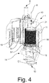
- Fig. 4
- die Vorrichtung der
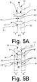
Fig. 3 mit offenem Gehäuse; - Fig. 5A
- eine schematische Darstellung des Rotors der
Figur 4 in der ersten Position; - Fig. 5B
- eine schematische Darstellung des Rotors der
Figur 4 beim Bewegen von der ersten Position in die zweite Position; - Fig. 6
- eine schematische Ansicht der Zufuhröffnung und der Auslassöffnung der Vorrichtung der
Figur 4 ; - Fig. 7A
- eine Prinzipskizze der Funktionsweise der Scherleiste in der ersten Position;
- Fig. 7B
- eine Prinzipskizze der Funktionsweise der Scherleiste beim Bewegen von der ersten Position in die zweite Position;
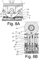
- Fig. 8A
- eine perspektivische Ansicht einer Steuerkurve mit Stempeln zur axialen Bewegung der Scherleisten;
- Fig. 8B
- eine teilweise Schnittansicht der Steuerkurve mit Stempeln;
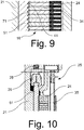
- Fig. 9
- eine Schnittansicht durch die Gehäusewand mit beweglichen Gehäusewandabschnitten; und
- Fig. 10
- eine Schnittansicht durch die Gehäusewand mit beweglichen Gehäusewandabschnitten und Bewegungssensor.
- In der
Figur 1 ist schematisch eine mögliche Ausgestaltung der erfindungsgemässen Vorrichtung dargestellt. - Die Vorrichtung 1 umfasst ein erstes Element 2 und ein zweites Element 5 mit je einer Durchgangsbohrung, die einen ersten und einen zweiten Aufnahmeabschnitt 4 bzw. 7 für ein Schüttgutkorn K ausbilden. Die Aufnahmeabschnitte 4 und 7 bilden somit eine Aufnahme für das Schüttgutkorn K. Die Durchgangsbohrung 7 ist gestrichelt dargestellt, da diese vom ersten Element 2 abgedeckt wird. Das erste und das zweite Element 2 und 5 weisen ferner je eine ebene Fläche 3 bzw. 6 auf, die zueinander parallel angeordnet sind. Die Durchgangsbohrungen 4 und 7 sind fluchtend ausgerichtet. Ein Durchgang 9 verbindet die erste Durchgangsbohrung 4 und die zweite Durchgangsbohrung 7.
- Beim Bewegen des ersten Elements 2 und/oder des zweiten Elements 5 entlang der Bewegungsrichtung M von der in der in der
Figur 1 gezeigten ersten Position P1 wird ein Querschnitt des Durchganges 9 verringert und das Schüttgutkorn durch Scherung zerkleinert. Das zerkleinerte Schüttgutkorn K kann dann aus der Vorrichtung 1 durch die Durchgangsbohrung 4 und/oder 7 entnommen werden. - Das erste Element 2 und das zweite Element 5 werden erfindungsgemäss mittels eines Antriebs hin-und-her zwischen der ersten Position P1 und einer zweiten, nicht gezeigten Position P2 bewegt. Die Bewegungsrichtung M liegt dabei in der Ebene der ersten Fläche 3 bzw. zweiten Fläche 6.
- In der
Figur 2 ist eine alternative Ausführungsform der Vorrichtung 1 in der ersten Position P1 gezeigt. - Im Unterschied zur Vorrichtung 1 der
Figur 1 sind jedoch die Aufnahmeabschnitte 4 und 7 als Vertiefung des jeweiligen Elements 2 bzw. 5 ausgebildet. - Auch in diesem Fall kann durch Bewegung des ersten Elements 2 und/oder des zweiten Elements 5 entlang der Bewegungsrichtung M von der in der in der
Figur 2 gezeigten ersten Position P1 ein Querschnitt des Durchganges 9 verringert und das Schüttgutkorn durch Scherung zerkleinert werden. - In der
Figur 3 ist eine erfindungsgemässe Vorrichtung 1 zum Zerkleinern von Schüttgutkörnern gezeigt. Die Vorrichtung 1 umfasst ein Gehäuse 11, welches eine Zufuhröffnung 8 und eine Auslassöffnung 12 für die Schuttgutkörner K aufweist. - In der
Figur 4 ist das Gehäuse 11 geöffnet, so dass der innere Aufbau der Vorrichtung 1 ersichtlich ist. Die Vorrichtung 1 umfasst einen Rotor 21 mit einer zylindrischen Umfangsfläche, welcher in denFiguren 5A und 5B schematisch dargestellt ist. Der Rotor 21 ist um eine Rotorachse A mittels Lagern 13 drehbar gelagert. Eine Motoreinheit 14 umfassend einen Motor und ein Getriebe dient als Rotorantrieb. - In den
Figuren 5A und 5B ist der Rotor 21 schematisch dargestellt. Der Rotor 21 weist an seiner Umfangsfläche eine Mehrzahl von umlaufenden Umfangsnuten 41, 41' auf, von denen nur zwei dargestellt sind, welche zur Aufnahme der Schüttgutkörner K ausgebildet sind. Jede Umlaufnut 41, 41' weist eine Breite B und eine in radialer Richtung des Rotors 21 sich erstreckende Tiefe T auf (welche in derFigur 7A gezeigt wird). - Der Rotor 21 weist ferner eine Mehrzahl von Scherleisten 51, 51' auf, von denen nur die Scherleiste 51 in den
Figuren 5A und 5B dargestellt ist. Die Scherleiste 51 ist in einer axialen Nut 10 des Rotors 21 angeordnet und entlang einer Bewegungsrichtung M verschiebbar. Die axiale Nut 10 kreuzt die Umlaufnut 41 (und 41'). Der Rotor weist somit eine Mehrzahl von axialen Nuten auf, wobei in derFiguren 5A und 5B nur eine axiale Nut 10 der Einfachheit halber dargestellt ist. - Es ist ersichtlich, dass die Funktionsweise der der Vorrichtung der
Figur 2 entspricht. Dabei ist der erste Aufnahmeabschnitt als Umlaufnut 41 ausgebildet, und die erste Fläche 3 entspricht einer Seitenwand 31 der axialen Nut 10. - Die Scherleiste 51 entspricht somit dem zweiten Element 5, wobei der zweite Aufnahmeabschnitt 7 als Vertiefung 71 der Scherleiste 51 ausgebildet ist. Eine Seitenfläche 61 der Scherleiste 51, welche an der Seitenwand 31 der axialen Nut 10 grenzt, entspricht demzufolge der zweiten Fläche 6 des zweiten Elements 5. Umlaufnut 41 und Vertiefung 71 weisen im Radialschnitt durch den Rotor 21 einen identischen Querschnitt auf und sind in der ersten Position P1 der
Figur 5A fluchtend ausgerichtet. - Beim Betreiben der Vorrichtung 1 werden die Schüttgutkörner K über die Zufuhröffnung 8 dem sich drehenden Rotor 21 zugeführt, wo sie in die Umlaufnuten 41, 41' gelangen und durch die Drehung des Rotors 21 mitgenommen werden.
- Ein Ende der Scherleisten 51, 51' wirkt mit einer Kurvenscheibe 15 zusammen, welche an einem stirnseitigen Ende des Rotors 21 angeordnet ist. Beim Drehen des Rotors 21, werden die Scherleisten 51, 51' somit zwischen einer ersten Position P1 (welche in der
Figur 5A gezeigt ist) und einer zweiten, nicht dargestellten Position P2 hin und her bewegt. Die damit einhergehende Verringerung des Querschnittes eines Überganges 9 zwischen der jeweiligen Umfangsnut 41, 41' und der Vertiefung 71, 71' der Scherleiste 51 im Bereich der Kreuzung zwischen den Umlaufnuten 41, 41' und axialen Nuten 10, 10' hat zur Folge, dass die Schüttgutkörnerkörner K zerkleinert werden. - Die Zerkleinerung ist in der
Figur 5B dargestellt. Wenn dabei die Breite B der Umlaufnut 41, 41' der Breite der Scherleiste 51 entspricht, kann somit gewährleistet werden, dass die Grössenverteilung der zerkleinerten Schüttgutkörner K maximal B entspricht. - Nach dem Schneiden der Schüttgutkörner werden diese aus der Umlaufnut 41, 41' entfernt und verlassen die Vorrichtung 1 durch die Auslassöffnung 12.
- In der
Figur 6 ist ein Detail der Zufuhr- und Abfuhreinrichtung der Vorrichtung 1 gesondert dargestellt. Die Zufuhr- 8 und Auslassöffnung 12 sind über eine Leitung mit entsprechenden Eingangsöffnungen 80 bzw. Ausgangsöffnungen 120 einer Gehäusewand 16 verbunden. Bei einer bevorzugten Ausführungsform sind zwischen 4 und 8 Eingangsöffnungen 80 bzw. Ausgangsöffnungen 120 umfänglich des Rotors 21 angeordnet, wobei in derFigur 6 nur eine Eingangsöffnung 80 und eine Ausgangsöffnung 120 gezeigt werden. Die Eingangsöffnung 80 ist mit einem Gitter 17 versehen. An der dem Rotor 21 abgewandten Seite ist ein Vorratsbehälter 18 angeordnet, welcher beim Betreiben der Vorrichtung 1 mit Schüttgutkörnern gefüllt wird, so dass sichergestellt werden kann, dass Schüttgutkörner über die gesamte Höhe dem Rotor 21 zugeführt werden können. Das Gitter 17 unterstützt die Ausbildung einer Schüttgutkörnersäule in dem Vorratsbehälter 18 und stellt sicher, dass nicht zu viele Schüttgutkörner zum Rotor 21 gelangen, welche zu Störungen der Vorrichtung 1 führen könnten. - In Drehrichtung R des Rotors 21 betrachtet, welche durch den Pfeil schematisch dargestellt ist, der Eingangsöffnung 80 nachgeordnet ist eine Ausgangsöffnung 120 angeordnet. An der Gehäusewand 16 ist eine Kammvorrichtung 19 befestigt. Die Kammvorrichtung 19 weist eine Mehrzahl von Fingern 20 auf, welche jeweils einer Umlaufnut 41, 41' der Vorrichtung zugewiesen sind. Die Finger 20 ragen in die jeweilige Umfangsnut 41, 41' hinein und bewirken, dass die zerkleinerten Schüttgutkörner aus der Umlaufnut 41, 41' entfernt werden und durch die Ausgangsöffnung 120 zur weiteren Verarbeitung die Vorrichtung 1 verlassen können.
- In den
Figuren 7A und 7B ist schematisch die Funktion der Kurvenscheibe 15 als möglicher Antrieb der Scherleisten 51, 51' dargestellt. Die Scherleiste 51 ist dabei mit nur einer Vertiefung 71 vereinfacht dargestellt. Die Kurvenscheibe 15 umfasst eine Umlaufnut 22, welche der Rotorachse A zugewandt ausgebildet ist. Am unteren Ende der Scherleiste 51 ist ein Vorsprung 23 ausgebildet, welcher in der Umlaufnut 22 Aufnahme findet. Beim Drehen des Rotors 21 wird die Scherleiste 51 mitgedreht, während die Kurvenscheibe 15 hingegen fest mit der Vorrichtung 1 verbunden ist. Die Umlaufnut 22 ist derart ausgebildet, dass die Scherleiste 51 beim Drehen axial zwischen der ersten Position P1 derFigur 7A und einer zweiten Position P2 bewegt wird. In derFigur 7B ist eine Zwischenposition zwischen der ersten Position P1 derFigur 7A und der zweiten Position P2, wobei die Umlaufnut 41 des Rotors 21 gestrichelt dargestellt ist, gezeigt. Zu vermerken ist, dass der Querschnitt der Durchganges 9 der Scherleiste 51 derFigur 7A und 7B trapezförmig mit einer Tiefe T ausgebildet ist. - In den
Figuren 8A und 8B ist eine weitere Ausgestaltung des Antriebs der Scherleisten 51, 51' dargestellt. Die Scherleisten 51, 51' usw. sind mit einem Halter 29 zug- und druckfest verbunden. Der Halter 29 ist wiederum zug- und druckfest mit einem Stempel 27 verbunden. Die Stempel 27 und 27' usw. (von denen lediglich zwei der Übersicht halber mit einem Bezugszeichen versehen sind) werden in einer zugeordneten Führungsbohrung 30 bzw. 30' des Rotors 21 axial bezüglich der Drehachse A des Rotors 21 geführt. Eine Spiralfeder 28 umgibt den jeweiligen Stempel 27, 27' usw. und ist an einem seiner Enden am Rotor 21 und am anderen Ende am jeweiligen Stempel 27 abgestützt. - Im Bereich des axialen Ende S des Rotors 21 sind mehrere Steuerkurven 26 angeordnet, von denen lediglich eine in den
Figuren 8A und 8B sichtbar sind. Die Steuerkurve 26 ist bezüglich einer Drehrichtung des Rotors 21 drehfest gelagert, so dass diese nicht bei drehendem Rotor 21 stationär bleibt, ist als kreisrundes Steuerrad ausgebildet und um die Achse Z frei - d.h. ohne einen Antrieb - drehbar gelagert. - Bei Drehung des Rotors 21 kommt ein oberer, linsenförmiger Kopf 32 des Stempels 27 in Kontakt mit der Mantelfläche 33 der Steuerkurve 26. Der Stempel 27 wird dabei bis zum Erreichen des Scheitels der Mantelfläche 33 zunächst nach unten gedrückt, wobei die Bewegungsrichtung des Stempels 27 im Wesentlichen parallel zur Drehachse A des Rotors 21 ist. Die Steuerkurve 26 wird gleichzeitig durch Reibung um die Achse Z gedreht.
- Durch die Bewegung des Stempels 27 werden die Scherleisten 51, 51' usw. von der ersten Position P1 in die zweite Position P2 bewegt. Der Stempel 27 wird dabei gegen eine Federkraft der Spiralfeder 28 bewegt. Die Spiralfeder 28 wird somit komprimiert.
- Durch die Federkraft der Spiralfeder 28 wird der Stempel 27 nach oben gedrückt. Durch die weitere Drehung des Rotors 21 und den Verlauf der Mantelfläche 33 wird der Stempel 27 wieder nach oben bewegt, bis der Halter 29 einen Anschlag gegen eine Anschlagsfläche des Rotors 21 erfährt. Die Scherleisten 51, 51' usw. kehren somit von der zweiten Position P2 in die Ausgangsposition, welche der ersten Position P1 entspricht.
- Um die Durchsatzleistung der Vorrichtung 1 zu erhöhen sind entsprechend der oben beschriebenen Beispiele mehrere Steuerkurven 26 vorgesehen, welche die Scherleisten 51, 51' usw. Zwischen der jeweiligen Eingangsöffnung 80 und Ausgangsöffnung 120 antreiben.
- In der
Figur 9 ist eine axiale Schnittansicht des Rotors 21 teilweise dargestellt. Die Gehäusewand 16 umfasst dabei eine Mehrzahl von Gehäusewandsegmenten 24, welche jeweils einer Umfangsnut 41 des Rotors 21 zugeordnet sind und in axialer Richtung des Rotors 21 nebeneinander angeordnet sind. Der Übersicht halber ist nur ein Gehäusewandabschnitt 24 mit einem Bezugszeichen versehen. - Jeder Gehäusewandabschnitt 24 wird durch eine Spiralfeder 34 in Richtung auf den Rotor 21 vorgespannt.
- Wie bereits oben erläutert bewirkt das trapezförmige Profil der Umfangsnut 41 und der Vertiefung 71, dass die Schüttgutkörner K beim Bewegen der Scherleiste 51 gegen die Gehäusewand 16 gedrückt werden.
- Die Vorspannkraft der Spiralfeder 34 ist so gewählt, dass die Gehäusewandabschnitte 24 beim Bewegen der Scherleiste 51 nicht verschoben werden. Gelangt jedoch ein Fremdkörper, welcher hart ist und somit von der Vorrichtung 1 nicht zerkleinert werden kann, in die Umfangsnut 41 und die Vertiefung 71, bewirkt das trapezförmige Profil, dass der Fremdkörper gegen den zugeordneten Gehäusewandabschnitt 24 gedrückt wird und diesen in radialer Richtung des Rotors 21 nach aussen verschiebt. Dadurch wird eine Beschädigung des Rotors 21 und insbesondere der Umfangsnut 41 bzw. der Vertiefung 71 der Scherleiste 51 weitestgehend vermieden.
- In der
Figur 10 eine bevorzugte Weiterbildung der Gehäusewand 16 gezeigt. Die Gehäusewand 16 umfasst eine Mehrzahl von beweglichen Gehäusewandabschnitten 24, welche analog zu den Gehäusewandabschnitten 24 derFigur 9 ausgebildet sind. Die Vorrichtung 1 umfasst zusätzlich einen Bewegungssensor 25. Der Bewegungssensor 25 umfasst dabei eine flexible Leitung 35, welche radial bezüglich der Drehachse A ausserhalb der Gehäusewand 16, unmittelbar hinten den Gehäusewandabschnitten 24, angeordnet ist. Die flexible Leitung 35 verläuft dabei parallel zur Drehachse A des Rotors 21 und ist bis zu einem Sollniveau mit einer Flüssigkeit gefüllt. - Ein nicht dargestellter Niveausensor überwacht dabei das Flüssigkeitsniveau. Die flexible Leitung 35 ist dabei so angeordnet, dass sie gequetscht wird, wenn ein Gehäusewandabschnitt 24 nach aussen verschoben wird, und damit eine Steigung des Flüssigkeitsniveaus verursacht wird. Der Niveausensor ermittelt dabei die Abweichung des Flüssigkeitsniveaus vom Sollniveau. Es kann somit erkannt werden, ob ein oder mehrere Gehäusewandabschnitte 24 verschoben worden sind und somit dass Gegenstände in der Vorrichtung 1 enthalten sind, welche nicht zerkleinert werden können.
Claims (15)
- Vorrichtung (1) zum Zerkleinern von Schüttgutkörnern, insbesondere von Getreidekörnern und -kernen, umfassend:- ein erstes Element (2) mit einer ersten Fläche (3) und einem ersten Aufnahmeabschnitt (4), wobei das erste Element (2) als um eine Rotorachse (A) drehbar gelagerter Rotor (21) mit einer zylindrischen Umfangsfläche ausgebildet ist, wobei der erste Aufnahmeabschnitt (4) eine zumindest teilweise ausgebildete Umfangsnut (41) ist, und der Rotor wenigstens eine axiale Nut (10) aufweist, welche die Umfangsnut (41) kreuzt, wobei die erste Fläche (3) eine Seitenwand (31) der axialen Nut (10) ist,- ein zweites Element (5) mit einer zweiten Fläche (6) und einem zweiten Aufnahmeabschnitt (7), wobei das zweite Element (5) als Scherleiste (51) ausgebildet und in der axialen Nut (10) hin-und-her beweglich entlang der axialen Nut (10) angeordnet ist, wobei der zweite Aufnahmeabschnitt (7) eine Aussparung (71) der Scherleiste (51) ist- eine Zufuhreinrichtung (8), wobeidie erste Fläche (3) und die zweite Fläche (6) zueinander parallel und zugewandt, bevorzugt sich berührend, angeordnet sind,
das erste Element (2) und das zweite Element (5) relativ zueinander hin-und-her zwischen einer ersten Position (P1) und einer zweiten Position (P2) bewegbar sind, wobei die Bewegungsrichtung in der Ebene der ersten und zweiten Fläche (3,6) liegt,
in der ersten Position (P1) der erste Aufnahmeabschnitt (4) und der zweite Aufnahmeabschnitt (7) über einen Durchgang (9) miteinander in Verbindung stehen und eine Aufnahme bilden, in welche ein Schüttgutkorn über die Zufuhreinrichtung (8) positionierbar ist,
beim Bewegen des ersten Elements (2) und des zweiten Elements (5) von der ersten Position (P1) in die zweite Position (P2) ein Querschnitt des Durchgangs (9) verengt wird. - Vorrichtung (1) nach Anspruch 1, ferner umfassend ein Gehäuse (11) mit einer Gehäusewand (16), welche den Rotor (21) zumindest abschnittsweise koaxial umgibt und wenigstens eine Zufuhröffnung (8) und wenigstens eine Auslassöffnung (12) für die Schüttgutkörner aufweist.
- Vorrichtung nach Anspruch 2, dadurch gekennzeichnet, dass die Gehäusewand (16) wenigstens einen beweglichen Gehäusewandabschnitt (24) aufweist, welcher radial bezüglich der Rotorachse (A) den ersten Aufnahmeabschnitt (4) überlappt, wobei der bewegliche Gehäusewandabschnitt (24) bevorzugt in Richtung des Rotors (21), insbesondere in radialer Richtung des Rotors (21), vorgespannt ist.
- Vorrichtung nach Anspruch 3, dadurch gekennzeichnet, dass der wenigstens eine bewegliche Gehäusewandabschnitt (24) mit einem Bewegungssensor (25) zur Ermittlung einer Bewegung des beweglichen Gehäusewandabschnittes (24) zusammenwirkt.
- Vorrichtung (1) nach Anspruch 1 bis 4, dadurch gekennzeichnet, dass die Rotorachse (A) vertikal angeordnet ist.
- Vorrichtung (1) nach einem der Ansprüche 1 bis 5, dadurch gekennzeichnet, dass die Umfangsnut (41) eine umlaufende Nut ist.
- Vorrichtung (1) nach einem der Ansprüche 1 bis 6, dadurch gekennzeichnet, dass die axiale Nut (10) sich über die gesamte Höhe des Rotors (21) erstreckt.
- Vorrichtung (1) nach einem der Ansprüche 1 bis 7, dadurch gekennzeichnet, dass die Umfangsnut (41) und die Aussparung (71) im Radialschnitt durch den Rotor (21) ein trapezförmiges Profil aufweisen.
- Vorrichtung (1) nach Anspruch 8, dadurch gekennzeichnet, dass die Umfangsnut (4) und die Aussparung (71) das Profil eines gleichschenkligen Trapezes aufweisen, wobei die kürzere Grundfläche des Trapezes parallel zur Rotorachse (A) angeordnet ist.
- Vorrichtung (1) nach einem der Ansprüche 1 bis 9, dadurch gekennzeichnet, dass der Rotor (21) eine Mehrzahl von Umfangsnuten (41, 41') aufweist.
- Vorrichtung (1) nach Anspruch 10, dadurch gekennzeichnet, dass die Scherleiste (51) eine Mehrzahl von Aussparungen (71, 71') umfasst, wobei in der ersten Position (P1) jede Aussparung (71, 71') einer Umlaufnut (41, 41') zugeordnet ist.
- Vorrichtung (1) nach Anspruch 11, dadurch gekennzeichnet, dass eine in der ersten Position (P1) einer ersten Umlaufnut (41, 41') zugeordnete Aussparung (71, 71') in der zweiten Position (P2) einer zweiten Umlaufnut (41', 41") zugeordnet ist, wobei die zweite Umlaufnut (41', 41") bevorzugt der ersten Umlaufnut (41, 41') benachbart angeordnet ist.
- Vorrichtung (1) nach einem der vorhergehenden Ansprüche,
dadurch gekennzeichnet, dass der Rotor (21) eine Mehrzahl von Scherleisten (51, 51') umfasst, welche jeweils in einer axialen Nut (10, 10') angeordnet sind. - Vorrichtung (1) nach einem der vorhergehenden Ansprüche,
dadurch gekennzeichnet, dass die Scherleiste (51) mittels eines Kurvengetriebes von der ersten Position (P1) in die zweite Position (P2) und/oder von der zweiten Position (P2) in die erste Position (P1) bewegbar ist, wobei das Kurvengetriebe wenigstens eine Steuerkurve (26) umfasst, welche bezüglich einer Drehrichtung des Rotors (21) drehfest an einem axialen Ende (S) des Rotors (21) angeordnet ist, wobei bei Drehung des Rotors (21) die Steuerkurve (26) ein axiales Ende der Scherleiste (51) axial bewegt, wobei vorzugsweise die Vorrichtung (1) ferner wenigstens einen in eine Führungsbohrung (30) des Rotors axial geführten Stempel (27) umfasst, wobei der Stempel (27) mit wenigstens einer Scherleiste (51) verbunden ist und bei Drehung des Rotors (21) von der Steuerkurve (26) axial bewegt wird. - Verfahren zur Verarbeitung von Schüttgutkörnern, umfassend die folgenden Schritte:- Zerkleinerung von Schüttgutkörnern mit einer Vorrichtung nach einem der vorhergehenden Ansprüche;- Weiterverarbeitung der zerkleinerten Schüttgutkörner oder Lagerung der zerkleinerten Schüttgutkörner; dadurch gekennzeichnet, dass kein Trennschritt zwischen dem Zerkleinerung- und dem Weiterverarbeitungs-/Lagerungsschritt durchgeführt wird und insbesondere, dass keine Produktrückführung der zerkleinerten Schüttgutkörner auf eine Vorrichtung zum Zerkleinern von Schüttgut stattfindet.
Priority Applications (5)
| Application Number | Priority Date | Filing Date | Title |
|---|---|---|---|
| PCT/EP2018/079567 WO2019086375A1 (de) | 2017-10-30 | 2018-10-29 | Vorrichtung und verfahren zum zerkleinern von schüttgutkörnern |
| US16/759,936 US11213828B2 (en) | 2017-10-30 | 2018-10-29 | Device and method for comminuting bulk material grains |
| CA3080660A CA3080660C (en) | 2017-10-30 | 2018-10-29 | Device and method for comminuting bulk material grains |
| RU2020117719A RU2745118C1 (ru) | 2017-10-30 | 2018-10-29 | Устройство и способ для измельчения насыпного зерна |
| UAA202003247A UA126347C2 (uk) | 2017-10-30 | 2018-10-29 | Пристрій і спосіб подрібнення зернового матеріалу в сипкій масі |
Applications Claiming Priority (1)
| Application Number | Priority Date | Filing Date | Title |
|---|---|---|---|
| EP17199189 | 2017-10-30 |
Publications (2)
| Publication Number | Publication Date |
|---|---|
| EP3476486A1 true EP3476486A1 (de) | 2019-05-01 |
| EP3476486B1 EP3476486B1 (de) | 2020-07-01 |
Family
ID=60191269
Family Applications (1)
| Application Number | Title | Priority Date | Filing Date |
|---|---|---|---|
| EP18202393.7A Active EP3476486B1 (de) | 2017-10-30 | 2018-10-24 | Vorrichtung und verfahren zum zerkleinern von schüttgutkörnern |
Country Status (6)
| Country | Link |
|---|---|
| US (1) | US11213828B2 (de) |
| EP (1) | EP3476486B1 (de) |
| CA (1) | CA3080660C (de) |
| RU (1) | RU2745118C1 (de) |
| UA (1) | UA126347C2 (de) |
| WO (1) | WO2019086375A1 (de) |
Families Citing this family (1)
| Publication number | Priority date | Publication date | Assignee | Title |
|---|---|---|---|---|
| EP3782733B1 (de) | 2019-08-20 | 2021-10-20 | Bühler AG | Scherleiste für vorrichtung zum zerkleinern von schüttgutkörnern |
Citations (5)
| Publication number | Priority date | Publication date | Assignee | Title |
|---|---|---|---|---|
| US1744169A (en) | 1926-03-26 | 1930-01-21 | Jr Theodore Kipp | Groat cutter |
| US2589307A (en) * | 1946-09-30 | 1952-03-18 | Symons Brothers Co | Grain cutter |
| DE1101110B (de) * | 1958-04-11 | 1961-03-02 | F B Lehmann G M B H Maschinenf | Brechvorrichtung zum Brechen von Kakaobohnen |
| PL176538B1 (pl) * | 1995-05-25 | 1999-06-30 | Akad Rolniczo Tech | Urządzenie do badań rozdrabniania materiałów ziarnistych H |
| EP1151797A1 (de) | 2000-05-05 | 2001-11-07 | The Quaker Oats Company | Rotierende Schneidemaschine für Granulatmaterial |
Family Cites Families (42)
| Publication number | Priority date | Publication date | Assignee | Title |
|---|---|---|---|---|
| DE657138C (de) | 1938-02-25 | Franz Abramowsky | Maschine zum Zerschneiden von Getreidekoernern | |
| CA257653A (en) | 1926-01-26 | The Kipp-Kelly | Rotary oatmeal cutter | |
| CA272090A (en) | 1927-07-05 | Theodore Kipp, Jr. | Groat cutter | |
| CA269343A (en) | 1927-03-29 | Theodore Kipp, Jr. | Groat cutter | |
| DE619661C (de) | 1935-10-05 | Albert Knigge | Schneidvorrichtung fuer die Zerlegung von Getreidekoernern | |
| US217844A (en) | 1879-07-22 | Improvement in oatmeal-machines | ||
| US673402A (en) | 1901-03-19 | 1901-05-07 | Harry Levy | Tobacco-cutting machine. |
| US1688770A (en) | 1922-07-10 | 1928-10-23 | Gump B F Co | Cereal-cutting machine |
| US1489503A (en) | 1923-05-22 | 1924-04-08 | John C Nichols | Harness-strap protector and coupling |
| US1584869A (en) * | 1923-06-21 | 1926-05-18 | Lester L Ladd | Grain-cutting apparatus |
| US1749925A (en) | 1924-05-24 | 1930-03-11 | Miag Muhlenbau Und Ind Ag | Apparatus for grinding grain into crushed malt and the like |
| GB243721A (en) | 1924-11-25 | 1926-08-26 | Josef Schaefer | An improved construction of fluted rolls for cutting grain |
| US1672945A (en) | 1926-03-26 | 1928-06-12 | Jr Theodore Kipp | Groat cutter |
| CH146524A (de) | 1930-02-14 | 1931-04-30 | Hansen August | Vorrichtung zum Zerkleinern von Getreidekörnern. |
| US1973169A (en) | 1931-11-28 | 1934-09-11 | Fred C Lelfield | Cereal cutter |
| DE592104C (de) | 1932-01-26 | 1934-02-01 | August Hansen | Vorrichtung zum Zerkleinern von Getreidekoernern mittels einer oder mehrerer umlaufender Messerwalzen |
| US1954613A (en) | 1932-02-25 | 1934-04-10 | Frank A Breeze | Cutting mechanism |
| DE612789C (de) | 1933-05-02 | 1935-05-04 | Wendelin Trapp | Getreideschneidmaschine |
| GB426589A (en) | 1934-05-30 | 1935-04-05 | Vendel Trapp | Improvements in or relating to machines for cutting grain |
| DE699223C (de) | 1937-08-05 | 1940-11-25 | August Hansen | Vorrichtung zum Zerkleinern von Getreidekoernern durch Zerschneiden |
| US2601490A (en) | 1948-06-01 | 1952-06-24 | David R Bailey | Apparatus for splitting almonds |
| US2597279A (en) | 1948-06-01 | 1952-05-20 | David R Bailey | Apparatus for halving almonds |
| DE819616C (de) | 1948-10-02 | 1951-11-05 | Miag Vertriebs Gmbh | Gruetzeschneider |
| US2884036A (en) * | 1953-09-11 | 1959-04-28 | Symons Brothers Co | Grain cutters with opposed eccentrically rotating blades |
| BE544069A (de) * | 1955-02-02 | |||
| DE1123537B (de) | 1959-11-26 | 1962-02-08 | Miag Muehlenbau & Ind Gmbh | Vorrichtung zum Zerschneiden von Getreidekoernern |
| DE1137290B (de) | 1960-03-31 | 1962-09-27 | Franz Pfeuffer | Schneidmaschine fuer Getreidekoerner |
| GB977636A (en) | 1960-10-05 | 1964-12-09 | Geza Eiben | Improvements in and relating to grain-shredding and disintegrating machines |
| US4189503A (en) | 1978-05-26 | 1980-02-19 | Cereal Enterprises, Inc. | Method of degerminating a kernel of grain by simultaneously compressing the edges of the kernel |
| ZA796612B (en) | 1979-12-05 | 1980-11-26 | Cereal Enterprises Inc | Grain milling and degerminating process |
| JPH01315351A (ja) * | 1988-06-15 | 1989-12-20 | Satake Eng Co Ltd | 研削式竪軸型精穀機 |
| RU21875U1 (ru) * | 1998-10-26 | 2002-02-27 | Опытное проектно-конструкторско-технологическое бюро Сибирского научно-исследовательского и проектно-технологического института животноводства | Трехстадийная дисковая мельница |
| US6634577B2 (en) * | 2000-12-20 | 2003-10-21 | Tsukuba Food Science, Inc. | Crusher, process for preparing and testing materials and apparatus therefor |
| AUPR912601A0 (en) * | 2001-11-27 | 2001-12-20 | Oldenburg Australasia Pty Ltd | A dual product sizing machine |
| JP3907547B2 (ja) * | 2002-08-02 | 2007-04-18 | ホソカワミクロン株式会社 | 気流乾燥装置 |
| RU2436633C2 (ru) * | 2009-07-29 | 2011-12-20 | Общество с ограниченной ответственностью "Научно-производственное предприятие "Эметрон" | Устройство для измельчения зерна |
| KR20110126299A (ko) | 2010-05-17 | 2011-11-23 | 농업회사법인 황금미가 유한회사 | 곡물 가공장치 |
| KR20120000589A (ko) | 2010-06-27 | 2012-01-04 | 농업회사법인 황금미가 유한회사 | 범용 곡물 가공장치 |
| RU2447942C2 (ru) * | 2010-06-30 | 2012-04-20 | Федеральное государственное образовательное учреждение высшего профессионального образования "Бурятская государственная сельскохозяйственная академия им. В.Р. Филиппова" | Центробежная многоступенчатая дробилка для зерна |
| DE102011105321B4 (de) | 2011-06-03 | 2018-08-30 | F.H. Schule Mühlenbau GmbH | Trommelschneidemaschine und Messerkorb für eine solche Maschine |
| CN202263626U (zh) | 2011-09-23 | 2012-06-06 | 武义金石制药机械有限公司 | 一种新型的制粒刀片 |
| KR101684972B1 (ko) * | 2014-07-01 | 2016-12-09 | 엘지전자 주식회사 | 음식물 처리장치 및 음식물 처리장치의 제어방법 |
-
2018
- 2018-10-24 EP EP18202393.7A patent/EP3476486B1/de active Active
- 2018-10-29 WO PCT/EP2018/079567 patent/WO2019086375A1/de not_active Ceased
- 2018-10-29 RU RU2020117719A patent/RU2745118C1/ru active
- 2018-10-29 CA CA3080660A patent/CA3080660C/en active Active
- 2018-10-29 US US16/759,936 patent/US11213828B2/en active Active
- 2018-10-29 UA UAA202003247A patent/UA126347C2/uk unknown
Patent Citations (5)
| Publication number | Priority date | Publication date | Assignee | Title |
|---|---|---|---|---|
| US1744169A (en) | 1926-03-26 | 1930-01-21 | Jr Theodore Kipp | Groat cutter |
| US2589307A (en) * | 1946-09-30 | 1952-03-18 | Symons Brothers Co | Grain cutter |
| DE1101110B (de) * | 1958-04-11 | 1961-03-02 | F B Lehmann G M B H Maschinenf | Brechvorrichtung zum Brechen von Kakaobohnen |
| PL176538B1 (pl) * | 1995-05-25 | 1999-06-30 | Akad Rolniczo Tech | Urządzenie do badań rozdrabniania materiałów ziarnistych H |
| EP1151797A1 (de) | 2000-05-05 | 2001-11-07 | The Quaker Oats Company | Rotierende Schneidemaschine für Granulatmaterial |
Also Published As
| Publication number | Publication date |
|---|---|
| WO2019086375A1 (de) | 2019-05-09 |
| EP3476486B1 (de) | 2020-07-01 |
| UA126347C2 (uk) | 2022-09-21 |
| CA3080660C (en) | 2021-04-20 |
| US20200391217A1 (en) | 2020-12-17 |
| US11213828B2 (en) | 2022-01-04 |
| RU2745118C1 (ru) | 2021-03-22 |
| CA3080660A1 (en) | 2019-05-09 |
Similar Documents
| Publication | Publication Date | Title |
|---|---|---|
| DE69232319T2 (de) | Lochscheibe für Zerkleinerungsmaschine | |
| EP3291915B1 (de) | Zerkleinerungsmaschine mit einem rotorsystem und verfahren zum zerkleinern von aufgabegut | |
| EP2987557B1 (de) | Zerkleinerungsmaschine zur zerkleinerung eines produkts | |
| EP3711862B1 (de) | Schneidvorrichtung; separierer; verfahren zum separieren von lebensmittelbestandteilen mittels eines separierers | |
| EP2065174B1 (de) | Füllvorrichtung für eine Rundlauf-Tablettenpresse | |
| EP1903102A1 (de) | Vorrichtung zur Förderung von Biomassematerialien | |
| DE112005001320B4 (de) | Brechvorrichtung | |
| DE19813485A1 (de) | Zerkleinerungs- und Zuteilungsvorrichtung für zerstückelbare, pumpbare Stoffe | |
| WO2014012693A2 (de) | Zerkleinerung von mahlgut in einer vertikalrollenmühle | |
| DE2256267B2 (de) | Mit Scherwirkung arbeitender Zerkleinerer | |
| EP3802093B1 (de) | Ablaufrutsche für eine tablettiermaschine sowie ein verfahren zum sortieren von presslingen nach deren herstellung in einer tablettiermaschine | |
| EP3613508B1 (de) | Verfahren zur ausschleusung schwer mahlbarer partikel aus einer spiralstrahlmühle | |
| DE3910115C3 (de) | Walzenbrecher | |
| EP3476486B1 (de) | Vorrichtung und verfahren zum zerkleinern von schüttgutkörnern | |
| DE102005055620B4 (de) | Vorrichtung zum Verarbeiten von Bauteilen aus Stoffgemischen | |
| CH660073A5 (de) | Vakuum-trocken-vorrichtung. | |
| EP3782733B1 (de) | Scherleiste für vorrichtung zum zerkleinern von schüttgutkörnern | |
| DE3313517A1 (de) | Granulator | |
| DE102005039200B4 (de) | Zerkleinerungsvorrichtung mit mehreren, im Wesentlichen parallel verlaufenden, motorisch angetriebenen, rotierenden oder oszillierenden Wellen | |
| DE19603557C2 (de) | Vorrichtung zum Emulgieren von zerkleinerten organischen Massen, Stoffen und/oder Flüssigkeiten | |
| DE3823676A1 (de) | Fleischwolf | |
| DE2531288C2 (de) | Vorrichtung zum Mahlen eines körnigen Lebensmittel-Mahlguts | |
| EP3541524B1 (de) | Scheraggregat zur gewinnung von gluten aus einem stärke- und glutenhaltigen gemisch | |
| EP2548648B1 (de) | Mühle zur Zerkleinerung von Mahlgut | |
| EP2549892B1 (de) | Messerbett für eine vorrichtung zum zerkleinern von organischen substanzen |
Legal Events
| Date | Code | Title | Description |
|---|---|---|---|
| PUAI | Public reference made under article 153(3) epc to a published international application that has entered the european phase |
Free format text: ORIGINAL CODE: 0009012 |
|
| STAA | Information on the status of an ep patent application or granted ep patent |
Free format text: STATUS: THE APPLICATION HAS BEEN PUBLISHED |
|
| AK | Designated contracting states |
Kind code of ref document: A1 Designated state(s): AL AT BE BG CH CY CZ DE DK EE ES FI FR GB GR HR HU IE IS IT LI LT LU LV MC MK MT NL NO PL PT RO RS SE SI SK SM TR |
|
| AX | Request for extension of the european patent |
Extension state: BA ME |
|
| STAA | Information on the status of an ep patent application or granted ep patent |
Free format text: STATUS: REQUEST FOR EXAMINATION WAS MADE |
|
| 17P | Request for examination filed |
Effective date: 20191029 |
|
| RBV | Designated contracting states (corrected) |
Designated state(s): AL AT BE BG CH CY CZ DE DK EE ES FI FR GB GR HR HU IE IS IT LI LT LU LV MC MK MT NL NO PL PT RO RS SE SI SK SM TR |
|
| GRAP | Despatch of communication of intention to grant a patent |
Free format text: ORIGINAL CODE: EPIDOSNIGR1 |
|
| STAA | Information on the status of an ep patent application or granted ep patent |
Free format text: STATUS: GRANT OF PATENT IS INTENDED |
|
| RIC1 | Information provided on ipc code assigned before grant |
Ipc: B02C 9/02 20060101AFI20191218BHEP |
|
| INTG | Intention to grant announced |
Effective date: 20200117 |
|
| GRAS | Grant fee paid |
Free format text: ORIGINAL CODE: EPIDOSNIGR3 |
|
| GRAA | (expected) grant |
Free format text: ORIGINAL CODE: 0009210 |
|
| STAA | Information on the status of an ep patent application or granted ep patent |
Free format text: STATUS: THE PATENT HAS BEEN GRANTED |
|
| AK | Designated contracting states |
Kind code of ref document: B1 Designated state(s): AL AT BE BG CH CY CZ DE DK EE ES FI FR GB GR HR HU IE IS IT LI LT LU LV MC MK MT NL NO PL PT RO RS SE SI SK SM TR |
|
| REG | Reference to a national code |
Ref country code: CH Ref legal event code: EP Ref country code: AT Ref legal event code: REF Ref document number: 1285653 Country of ref document: AT Kind code of ref document: T Effective date: 20200715 |
|
| REG | Reference to a national code |
Ref country code: IE Ref legal event code: FG4D Free format text: LANGUAGE OF EP DOCUMENT: GERMAN |
|
| REG | Reference to a national code |
Ref country code: DE Ref legal event code: R096 Ref document number: 502018001791 Country of ref document: DE |
|
| REG | Reference to a national code |
Ref country code: LT Ref legal event code: MG4D |
|
| PG25 | Lapsed in a contracting state [announced via postgrant information from national office to epo] |
Ref country code: BG Free format text: LAPSE BECAUSE OF FAILURE TO SUBMIT A TRANSLATION OF THE DESCRIPTION OR TO PAY THE FEE WITHIN THE PRESCRIBED TIME-LIMIT Effective date: 20201001 |
|
| REG | Reference to a national code |
Ref country code: NL Ref legal event code: MP Effective date: 20200701 |
|
| PG25 | Lapsed in a contracting state [announced via postgrant information from national office to epo] |
Ref country code: CZ Free format text: LAPSE BECAUSE OF FAILURE TO SUBMIT A TRANSLATION OF THE DESCRIPTION OR TO PAY THE FEE WITHIN THE PRESCRIBED TIME-LIMIT Effective date: 20200701 Ref country code: FI Free format text: LAPSE BECAUSE OF FAILURE TO SUBMIT A TRANSLATION OF THE DESCRIPTION OR TO PAY THE FEE WITHIN THE PRESCRIBED TIME-LIMIT Effective date: 20200701 Ref country code: SE Free format text: LAPSE BECAUSE OF FAILURE TO SUBMIT A TRANSLATION OF THE DESCRIPTION OR TO PAY THE FEE WITHIN THE PRESCRIBED TIME-LIMIT Effective date: 20200701 Ref country code: PT Free format text: LAPSE BECAUSE OF FAILURE TO SUBMIT A TRANSLATION OF THE DESCRIPTION OR TO PAY THE FEE WITHIN THE PRESCRIBED TIME-LIMIT Effective date: 20201102 Ref country code: HR Free format text: LAPSE BECAUSE OF FAILURE TO SUBMIT A TRANSLATION OF THE DESCRIPTION OR TO PAY THE FEE WITHIN THE PRESCRIBED TIME-LIMIT Effective date: 20200701 Ref country code: LT Free format text: LAPSE BECAUSE OF FAILURE TO SUBMIT A TRANSLATION OF THE DESCRIPTION OR TO PAY THE FEE WITHIN THE PRESCRIBED TIME-LIMIT Effective date: 20200701 Ref country code: NO Free format text: LAPSE BECAUSE OF FAILURE TO SUBMIT A TRANSLATION OF THE DESCRIPTION OR TO PAY THE FEE WITHIN THE PRESCRIBED TIME-LIMIT Effective date: 20201001 Ref country code: GR Free format text: LAPSE BECAUSE OF FAILURE TO SUBMIT A TRANSLATION OF THE DESCRIPTION OR TO PAY THE FEE WITHIN THE PRESCRIBED TIME-LIMIT Effective date: 20201002 Ref country code: ES Free format text: LAPSE BECAUSE OF FAILURE TO SUBMIT A TRANSLATION OF THE DESCRIPTION OR TO PAY THE FEE WITHIN THE PRESCRIBED TIME-LIMIT Effective date: 20200701 |
|
| PG25 | Lapsed in a contracting state [announced via postgrant information from national office to epo] |
Ref country code: LV Free format text: LAPSE BECAUSE OF FAILURE TO SUBMIT A TRANSLATION OF THE DESCRIPTION OR TO PAY THE FEE WITHIN THE PRESCRIBED TIME-LIMIT Effective date: 20200701 Ref country code: PL Free format text: LAPSE BECAUSE OF FAILURE TO SUBMIT A TRANSLATION OF THE DESCRIPTION OR TO PAY THE FEE WITHIN THE PRESCRIBED TIME-LIMIT Effective date: 20200701 Ref country code: RS Free format text: LAPSE BECAUSE OF FAILURE TO SUBMIT A TRANSLATION OF THE DESCRIPTION OR TO PAY THE FEE WITHIN THE PRESCRIBED TIME-LIMIT Effective date: 20200701 Ref country code: IS Free format text: LAPSE BECAUSE OF FAILURE TO SUBMIT A TRANSLATION OF THE DESCRIPTION OR TO PAY THE FEE WITHIN THE PRESCRIBED TIME-LIMIT Effective date: 20201101 |
|
| PG25 | Lapsed in a contracting state [announced via postgrant information from national office to epo] |
Ref country code: NL Free format text: LAPSE BECAUSE OF FAILURE TO SUBMIT A TRANSLATION OF THE DESCRIPTION OR TO PAY THE FEE WITHIN THE PRESCRIBED TIME-LIMIT Effective date: 20200701 |
|
| REG | Reference to a national code |
Ref country code: DE Ref legal event code: R097 Ref document number: 502018001791 Country of ref document: DE |
|
| PG25 | Lapsed in a contracting state [announced via postgrant information from national office to epo] |
Ref country code: EE Free format text: LAPSE BECAUSE OF FAILURE TO SUBMIT A TRANSLATION OF THE DESCRIPTION OR TO PAY THE FEE WITHIN THE PRESCRIBED TIME-LIMIT Effective date: 20200701 Ref country code: RO Free format text: LAPSE BECAUSE OF FAILURE TO SUBMIT A TRANSLATION OF THE DESCRIPTION OR TO PAY THE FEE WITHIN THE PRESCRIBED TIME-LIMIT Effective date: 20200701 Ref country code: DK Free format text: LAPSE BECAUSE OF FAILURE TO SUBMIT A TRANSLATION OF THE DESCRIPTION OR TO PAY THE FEE WITHIN THE PRESCRIBED TIME-LIMIT Effective date: 20200701 Ref country code: SM Free format text: LAPSE BECAUSE OF FAILURE TO SUBMIT A TRANSLATION OF THE DESCRIPTION OR TO PAY THE FEE WITHIN THE PRESCRIBED TIME-LIMIT Effective date: 20200701 |
|
| PLBE | No opposition filed within time limit |
Free format text: ORIGINAL CODE: 0009261 |
|
| STAA | Information on the status of an ep patent application or granted ep patent |
Free format text: STATUS: NO OPPOSITION FILED WITHIN TIME LIMIT |
|
| PG25 | Lapsed in a contracting state [announced via postgrant information from national office to epo] |
Ref country code: AL Free format text: LAPSE BECAUSE OF FAILURE TO SUBMIT A TRANSLATION OF THE DESCRIPTION OR TO PAY THE FEE WITHIN THE PRESCRIBED TIME-LIMIT Effective date: 20200701 |
|
| 26N | No opposition filed |
Effective date: 20210406 |
|
| PG25 | Lapsed in a contracting state [announced via postgrant information from national office to epo] |
Ref country code: LU Free format text: LAPSE BECAUSE OF NON-PAYMENT OF DUE FEES Effective date: 20201024 Ref country code: SK Free format text: LAPSE BECAUSE OF FAILURE TO SUBMIT A TRANSLATION OF THE DESCRIPTION OR TO PAY THE FEE WITHIN THE PRESCRIBED TIME-LIMIT Effective date: 20200701 Ref country code: MC Free format text: LAPSE BECAUSE OF FAILURE TO SUBMIT A TRANSLATION OF THE DESCRIPTION OR TO PAY THE FEE WITHIN THE PRESCRIBED TIME-LIMIT Effective date: 20200701 |
|
| REG | Reference to a national code |
Ref country code: BE Ref legal event code: MM Effective date: 20201031 |
|
| PG25 | Lapsed in a contracting state [announced via postgrant information from national office to epo] |
Ref country code: FR Free format text: LAPSE BECAUSE OF NON-PAYMENT OF DUE FEES Effective date: 20201031 |
|
| PG25 | Lapsed in a contracting state [announced via postgrant information from national office to epo] |
Ref country code: SI Free format text: LAPSE BECAUSE OF FAILURE TO SUBMIT A TRANSLATION OF THE DESCRIPTION OR TO PAY THE FEE WITHIN THE PRESCRIBED TIME-LIMIT Effective date: 20200701 Ref country code: BE Free format text: LAPSE BECAUSE OF NON-PAYMENT OF DUE FEES Effective date: 20201031 |
|
| PG25 | Lapsed in a contracting state [announced via postgrant information from national office to epo] |
Ref country code: IE Free format text: LAPSE BECAUSE OF NON-PAYMENT OF DUE FEES Effective date: 20201024 |
|
| REG | Reference to a national code |
Ref country code: CH Ref legal event code: PL |
|
| PG25 | Lapsed in a contracting state [announced via postgrant information from national office to epo] |
Ref country code: MT Free format text: LAPSE BECAUSE OF FAILURE TO SUBMIT A TRANSLATION OF THE DESCRIPTION OR TO PAY THE FEE WITHIN THE PRESCRIBED TIME-LIMIT Effective date: 20200701 Ref country code: CY Free format text: LAPSE BECAUSE OF FAILURE TO SUBMIT A TRANSLATION OF THE DESCRIPTION OR TO PAY THE FEE WITHIN THE PRESCRIBED TIME-LIMIT Effective date: 20200701 |
|
| PG25 | Lapsed in a contracting state [announced via postgrant information from national office to epo] |
Ref country code: MK Free format text: LAPSE BECAUSE OF FAILURE TO SUBMIT A TRANSLATION OF THE DESCRIPTION OR TO PAY THE FEE WITHIN THE PRESCRIBED TIME-LIMIT Effective date: 20200701 |
|
| PG25 | Lapsed in a contracting state [announced via postgrant information from national office to epo] |
Ref country code: LI Free format text: LAPSE BECAUSE OF NON-PAYMENT OF DUE FEES Effective date: 20211031 Ref country code: CH Free format text: LAPSE BECAUSE OF NON-PAYMENT OF DUE FEES Effective date: 20211031 |
|
| GBPC | Gb: european patent ceased through non-payment of renewal fee |
Effective date: 20221024 |
|
| P01 | Opt-out of the competence of the unified patent court (upc) registered |
Effective date: 20230523 |
|
| PG25 | Lapsed in a contracting state [announced via postgrant information from national office to epo] |
Ref country code: GB Free format text: LAPSE BECAUSE OF NON-PAYMENT OF DUE FEES Effective date: 20221024 |
|
| REG | Reference to a national code |
Ref country code: AT Ref legal event code: MM01 Ref document number: 1285653 Country of ref document: AT Kind code of ref document: T Effective date: 20231024 |
|
| PG25 | Lapsed in a contracting state [announced via postgrant information from national office to epo] |
Ref country code: AT Free format text: LAPSE BECAUSE OF NON-PAYMENT OF DUE FEES Effective date: 20231024 |
|
| PG25 | Lapsed in a contracting state [announced via postgrant information from national office to epo] |
Ref country code: AT Free format text: LAPSE BECAUSE OF NON-PAYMENT OF DUE FEES Effective date: 20231024 |
|
| PGFP | Annual fee paid to national office [announced via postgrant information from national office to epo] |
Ref country code: DE Payment date: 20251020 Year of fee payment: 8 |
|
| PGFP | Annual fee paid to national office [announced via postgrant information from national office to epo] |
Ref country code: IT Payment date: 20251031 Year of fee payment: 8 |
|
| PGFP | Annual fee paid to national office [announced via postgrant information from national office to epo] |
Ref country code: TR Payment date: 20251022 Year of fee payment: 8 |
|
| PGFP | Annual fee paid to national office [announced via postgrant information from national office to epo] |
Ref country code: AT Payment date: 20260410 Year of fee payment: 5 |